EP0178083A1 - Assay technique and equipment - Google Patents
Assay technique and equipment Download PDFInfo
- Publication number
- EP0178083A1 EP0178083A1 EP85306577A EP85306577A EP0178083A1 EP 0178083 A1 EP0178083 A1 EP 0178083A1 EP 85306577 A EP85306577 A EP 85306577A EP 85306577 A EP85306577 A EP 85306577A EP 0178083 A1 EP0178083 A1 EP 0178083A1
- Authority
- EP
- European Patent Office
- Prior art keywords
- article
- fluorescent
- species
- binding
- dye
- Prior art date
- Legal status (The legal status is an assumption and is not a legal conclusion. Google has not performed a legal analysis and makes no representation as to the accuracy of the status listed.)
- Granted
Links
Images

Classifications
-
- G—PHYSICS
- G01—MEASURING; TESTING
- G01N—INVESTIGATING OR ANALYSING MATERIALS BY DETERMINING THEIR CHEMICAL OR PHYSICAL PROPERTIES
- G01N21/00—Investigating or analysing materials by the use of optical means, i.e. using sub-millimetre waves, infrared, visible or ultraviolet light
- G01N21/62—Systems in which the material investigated is excited whereby it emits light or causes a change in wavelength of the incident light
- G01N21/63—Systems in which the material investigated is excited whereby it emits light or causes a change in wavelength of the incident light optically excited
- G01N21/64—Fluorescence; Phosphorescence
- G01N21/645—Specially adapted constructive features of fluorimeters
- G01N21/648—Specially adapted constructive features of fluorimeters using evanescent coupling or surface plasmon coupling for the excitation of fluorescence
-
- G—PHYSICS
- G01—MEASURING; TESTING
- G01N—INVESTIGATING OR ANALYSING MATERIALS BY DETERMINING THEIR CHEMICAL OR PHYSICAL PROPERTIES
- G01N21/00—Investigating or analysing materials by the use of optical means, i.e. using sub-millimetre waves, infrared, visible or ultraviolet light
- G01N21/17—Systems in which incident light is modified in accordance with the properties of the material investigated
- G01N21/47—Scattering, i.e. diffuse reflection
- G01N21/4788—Diffraction
-
- G—PHYSICS
- G01—MEASURING; TESTING
- G01N—INVESTIGATING OR ANALYSING MATERIALS BY DETERMINING THEIR CHEMICAL OR PHYSICAL PROPERTIES
- G01N21/00—Investigating or analysing materials by the use of optical means, i.e. using sub-millimetre waves, infrared, visible or ultraviolet light
- G01N21/62—Systems in which the material investigated is excited whereby it emits light or causes a change in wavelength of the incident light
- G01N21/63—Systems in which the material investigated is excited whereby it emits light or causes a change in wavelength of the incident light optically excited
- G01N21/64—Fluorescence; Phosphorescence
- G01N21/6428—Measuring fluorescence of fluorescent products of reactions or of fluorochrome labelled reactive substances, e.g. measuring quenching effects, using measuring "optrodes"
-
- G—PHYSICS
- G01—MEASURING; TESTING
- G01N—INVESTIGATING OR ANALYSING MATERIALS BY DETERMINING THEIR CHEMICAL OR PHYSICAL PROPERTIES
- G01N33/00—Investigating or analysing materials by specific methods not covered by groups G01N1/00 - G01N31/00
- G01N33/48—Biological material, e.g. blood, urine; Haemocytometers
- G01N33/50—Chemical analysis of biological material, e.g. blood, urine; Testing involving biospecific ligand binding methods; Immunological testing
- G01N33/53—Immunoassay; Biospecific binding assay; Materials therefor
- G01N33/543—Immunoassay; Biospecific binding assay; Materials therefor with an insoluble carrier for immobilising immunochemicals
- G01N33/54366—Apparatus specially adapted for solid-phase testing
- G01N33/54373—Apparatus specially adapted for solid-phase testing involving physiochemical end-point determination, e.g. wave-guides, FETS, gratings
-
- G—PHYSICS
- G01—MEASURING; TESTING
- G01N—INVESTIGATING OR ANALYSING MATERIALS BY DETERMINING THEIR CHEMICAL OR PHYSICAL PROPERTIES
- G01N33/00—Investigating or analysing materials by specific methods not covered by groups G01N1/00 - G01N31/00
- G01N33/48—Biological material, e.g. blood, urine; Haemocytometers
- G01N33/50—Chemical analysis of biological material, e.g. blood, urine; Testing involving biospecific ligand binding methods; Immunological testing
- G01N33/53—Immunoassay; Biospecific binding assay; Materials therefor
- G01N33/543—Immunoassay; Biospecific binding assay; Materials therefor with an insoluble carrier for immobilising immunochemicals
- G01N33/544—Immunoassay; Biospecific binding assay; Materials therefor with an insoluble carrier for immobilising immunochemicals the carrier being organic
- G01N33/545—Synthetic resin
-
- G—PHYSICS
- G01—MEASURING; TESTING
- G01N—INVESTIGATING OR ANALYSING MATERIALS BY DETERMINING THEIR CHEMICAL OR PHYSICAL PROPERTIES
- G01N33/00—Investigating or analysing materials by specific methods not covered by groups G01N1/00 - G01N31/00
- G01N33/48—Biological material, e.g. blood, urine; Haemocytometers
- G01N33/50—Chemical analysis of biological material, e.g. blood, urine; Testing involving biospecific ligand binding methods; Immunological testing
- G01N33/53—Immunoassay; Biospecific binding assay; Materials therefor
- G01N33/543—Immunoassay; Biospecific binding assay; Materials therefor with an insoluble carrier for immobilising immunochemicals
- G01N33/551—Immunoassay; Biospecific binding assay; Materials therefor with an insoluble carrier for immobilising immunochemicals the carrier being inorganic
- G01N33/553—Metal or metal coated
-
- G—PHYSICS
- G01—MEASURING; TESTING
- G01N—INVESTIGATING OR ANALYSING MATERIALS BY DETERMINING THEIR CHEMICAL OR PHYSICAL PROPERTIES
- G01N21/00—Investigating or analysing materials by the use of optical means, i.e. using sub-millimetre waves, infrared, visible or ultraviolet light
- G01N21/62—Systems in which the material investigated is excited whereby it emits light or causes a change in wavelength of the incident light
- G01N21/63—Systems in which the material investigated is excited whereby it emits light or causes a change in wavelength of the incident light optically excited
- G01N21/64—Fluorescence; Phosphorescence
- G01N21/6428—Measuring fluorescence of fluorescent products of reactions or of fluorochrome labelled reactive substances, e.g. measuring quenching effects, using measuring "optrodes"
- G01N2021/6432—Quenching
-
- G—PHYSICS
- G01—MEASURING; TESTING
- G01N—INVESTIGATING OR ANALYSING MATERIALS BY DETERMINING THEIR CHEMICAL OR PHYSICAL PROPERTIES
- G01N21/00—Investigating or analysing materials by the use of optical means, i.e. using sub-millimetre waves, infrared, visible or ultraviolet light
- G01N21/62—Systems in which the material investigated is excited whereby it emits light or causes a change in wavelength of the incident light
- G01N21/63—Systems in which the material investigated is excited whereby it emits light or causes a change in wavelength of the incident light optically excited
- G01N21/64—Fluorescence; Phosphorescence
- G01N21/6408—Fluorescence; Phosphorescence with measurement of decay time, time resolved fluorescence
-
- Y—GENERAL TAGGING OF NEW TECHNOLOGICAL DEVELOPMENTS; GENERAL TAGGING OF CROSS-SECTIONAL TECHNOLOGIES SPANNING OVER SEVERAL SECTIONS OF THE IPC; TECHNICAL SUBJECTS COVERED BY FORMER USPC CROSS-REFERENCE ART COLLECTIONS [XRACs] AND DIGESTS
- Y10—TECHNICAL SUBJECTS COVERED BY FORMER USPC
- Y10S—TECHNICAL SUBJECTS COVERED BY FORMER USPC CROSS-REFERENCE ART COLLECTIONS [XRACs] AND DIGESTS
- Y10S436/00—Chemistry: analytical and immunological testing
- Y10S436/805—Optical property
-
- Y—GENERAL TAGGING OF NEW TECHNOLOGICAL DEVELOPMENTS; GENERAL TAGGING OF CROSS-SECTIONAL TECHNOLOGIES SPANNING OVER SEVERAL SECTIONS OF THE IPC; TECHNICAL SUBJECTS COVERED BY FORMER USPC CROSS-REFERENCE ART COLLECTIONS [XRACs] AND DIGESTS
- Y10—TECHNICAL SUBJECTS COVERED BY FORMER USPC
- Y10S—TECHNICAL SUBJECTS COVERED BY FORMER USPC CROSS-REFERENCE ART COLLECTIONS [XRACs] AND DIGESTS
- Y10S436/00—Chemistry: analytical and immunological testing
- Y10S436/807—Apparatus included in process claim, e.g. physical support structures
- Y10S436/81—Tube, bottle, or dipstick
Definitions
- the angles of absorption and emission are determined by the relationship:
- the reflected power at the absorption and fluorescent wavelengths varies as a function of incident angle in the manner shown in Figures 2a and 2b.
- the reflected power at the absorption wavelength behaves in the usual way for plasmon resonance.
- the reflected power at the fluorescent wavelength increases as the amount of bound analyte increases, and the maximum in the curve occurs at the angle of incidence which excites the maximum plasmon resonance.
Abstract
Description
- This invention relates to an assay technique for qualitative and/or quantitative detection of chemical, biochemical or biological species in a sample and to apparatus and equipment for use in such a technique.
- The technique is based' upon the affinity of the species which is to be assayed for a receptive material, for example a ligand or a specific binding partner, which receptive material is coated onto a particular type of surface.
- Our International Patent Publication No. W084/02578 describes and claims an assay technique for qualitative and/or quantitative detection of a chemical, biochemical or biological species in a sample, which comprises (a) coating at least a predetermined part of a surface having a pre-formed relief profile on a substrate with a thin film of a material capable of binding the species to be assayed, said surface part being optically active with respect to radiation at least over a predetermined band of wavelengths; (b) contacting the coated surface with the sample; and (c) observing the optical properties of said surface part in order to determine a qualitative and/or quantitative change in optical properties as a result of the binding of the species onto said thin film of material. The same publication also describes and claims an article for use in such an assay technique, the article comprising a substrate having a surface with a pre-formed relief profile which is optically active with respect to radiation at least over a predetermined band of wavelengths, and at least a predetermined part of which surface is coated with a thin film of a material capable of binding a predetermined chemical or biochemical or biological species. The substrate is most preferably a lamellar plastics material and may conveniently be in strip-form. The pre-formed surface relief profile may take a variety of forms, but broadly speaking the profile may be referred to as a grating. It may consist of a single grating or of two or more crossed gratings. The grating profile may be square-wave, sinusoidal or saw-tooth, for example; it may also be derived from the arrangement of a series of protuberances formed on the surface.
- It will be convenient hereinafter to use the term "grating" to refer to a surface with a pre-formed relief profile of the type disclosed in our International Patent Publication W084/02578. It will be appreciated that the surface which constitutes the grating may be of the same material as the substrate itself, or it may be of a different material (in which case the substrate will carry said different material).
- Our International Patent Publication No. W084/02578 discloses an invention of which a key characteristic is the use of a grating in an assay technique. It effectively marries the optical effects which may be achieved using gratings with the chemical or biochemical techniques used in molecular assays in order to improve such assays. The disclosure of International Patent Publication No.W084/02578 is incorporated herein by reference thereto. Our present understanding of the mechanistic aspects of this earlier invention is that the change in optical properties of the article as a result of the binding of a species to be assayed (e.g. a specific antigen in blood serum) is brought about essentially as a result of (i) the mass or bulk of bound molecules and (ii) their dielectric properties. Sensitivity however will depend on the size of the antigen molecule concerned: more small molecules will need to be bound than large molecules in order to produce the same change in optical properties (assuming the dielectric properties of the different molecules are unchanged). Although the technique of this earlier invention constitutes a considerable advance in the art, nevertheless this dependence on molecular size and dielectric properties does limit the application of the technique. The present invention aims to overcome or ameliorate this limitation of the earlier invention.
- Because surface phenomena greatly affect both the physical and the chemical aspects of a measuring technique involving the use of active molecules attached to a grating surface, it is not possible to predict, a priori, how an article as described and claimed in our International Patent Publication No.W084/02578 would behave if it were modified by the incorporation of additional molecules into the thin film of material which is capable of binding the species to be assayed. After extensive investigations, we have now found, surprisingly, that very large increases in measurement sensitivity can be achieved if the active layer (i.e. the thin film of material capable of binding the species to be assayed) formed over the grating is tagged with a fluorescent molecule; furthermore, the sensitivity of the system is much less dependent on the size or bulk of the bound molecules and on their dielectric properties. Accordingly, in one aspect of the present invention, there is provided an article for use in an assay technique for qualitative and/or quantitative detection of a chemical, biochemical or biological species in a sample, which article comprises a substrate having or carrying a surface with a pre-formed relief profile which is optically active with respect to radiation at least over a predetermined band of wavelengths, and at least a predetermined part of which surface is coated with a thin film of a material capable of binding a predetermined chemical or biochemical or biological species, said thin film of material incorporating molecules of a fluorescent compound whose fluorescent properties show an observable dependence upon its molecular environment.
- The pre-formed relief profile is preferably a grating. A single grating may be employed, or the surface may comprise two or more gratings disposed mutually at an angle. Where there are two such gratings, they may be mutually orthogonal. The profile of the or each grating is advantageously square-wave or sinusoidal. Sinusoidal gratings are presently preferred. Saw-tooth profiles are also possible, but are not presently preferred.
- The pre-formed relief profile may alternatively comprise a regular array of protuberances. With a surface of this type, the alignment of the peaks of the protuberances and the troughs between the protuberances corresponds to the ridges and troughs of a grating-type structure.
- A monomolecular layer of the receptive material will suffice and will generally be preferred.
- The pre-formed relief profile may be present at the surface of the substrate, or at the surface of a layer carried by the substrate.
- Conveniently, the substrate is formed of a plastics material. A presently preferred plastics material is polymethylmethacrylate. An alternative substrate is a glass coated with a synthetic polymeric material. Where the pre-formed relief profile is generated in a plastics material, then plastics materials curable by ultra-violet light are preferred, and in particular acrylic or polyester materials can advantageously be used; the plastics material preferably has a refractive index in the range 1.25 to 1.6, and more preferably a refractive index of about 1.4.
- The active surface of the article (i.e., that surface which is, or which carries, the pre-formed surface) will generally be constituted by a metal or a metal layer. Thus a plastics substrate, e.g., of polymethylmethacrylate, can have adhering thereto a layer of a UV-curable polyester material in which the desired relief profile is generated; and a thin metal layer which conforms to the pre-formed relief profile (e.g. a single grating structure of depth about 30 nanometers and period about 600 nanometers) adheres thereto. The plastics/metal interface may alternatively be planar: In which case the desired relief is generated directly in the metal.
- Generally, the substrate will be lamellar. It may be in strip-form.
- The grating structure adopted for an article in accordance with the present invention is preferably a metallised shallow grating i.e. a diffraction grating having a depth (peak-to-trough) of up to 400 nanometers, preferably of from 30 to 100 nanometers, and a pitch (period) which is greater than the grating depth and is generally in the range from 400 to 2000 nanometers. The overcoating metal layer is preferably of silver or aluminium and has a thickness of up to 500 nanometers, preferably 100 plus or
minus 10 nm. Less preferred overcoating metals are gold and copper. Ideally, the metal layer should be highly reflecting at both the absorption (i.e. dye excitation) wavelength and at the fluorescence wavelength. A passivation or capping layer of, for example, an oxide of silicon or of aluminium may advantageously coat the metal itself. - A dye molecule or residue may be bound to the active layer so that the dye molecule or residue is remote from the metallised grating surface. Alternatively, a dye molecule or residue may be bound directly to the surface of the metallised grating and the active layer, e.g. of antigen, may then be bound to the dye molecule. With either arrangement, the dye (fluorochrome) to metal distance is preferably 10 nm or more in order to optimise absorption of incident radiation by the dye molecule or residue.
- The binding of the active layer to the grating and of the dye (fluorochrome) to the grating and/or to the active layer is effected by conventional techniques which do not themselves form a part of the present invention.
- If desired, a dye molecule or residue which is to be incorporated into the surface structure of an article in accordance with this invention may incorporated in a phospholipid layer in order to control the surface distribution and concentration of dye molecules in the resultant article.
- The dye or dyes for use in an article in accordance with this invention preferably absorb strongly at the emission wavelength of a suitable laser which may thus constitute the excitation source. Examples of suitable layers are: Argon ion (488 nm); HeNe (543 nm); frequency doubled YAG (532 nm); and frequency tripled YAG (355 nm). Sources such as these are known per se and their design and construction does not of itself form a part of the present invention. The dyes used will generally absorb in the blue/green parts of the visible spectrum and will fluoresce in the green/red/infrared. Typically, dyes of the coumarin, rhodamine or fluorescein families, or the ion Eu will be used.
- In a preferred embodiment of an article in accordance with this invention, the dye may be located in a sensitive molecular environment which is such that fluorescence is quenched after binding of the species undergoing assay but is activated in the absence of such species; the reverse arrangement - i.e. in which binding of the species activates fluorescence, which is otherwise quenched by the molecular environment of the dye - is equally preferred. In these embodiments, a single measurement taken after the article has been subjected to the species undergoing assay may suffice, after appropriate calibration, to determine the quantity of species present in the sample.
- According to another aspect of the present invention, there is provided an assay technique in which an article as hereinbefore defined is subjected to a fluid containing the species to be assayed, said thin film of material carried by the article being selected in accordance with the species to be assayed, wherein a comparison is made between the fluorescent properties of said dye molecule after and before binding of the species undergoing assay. Preferably, incident radiation is directed at the surface of said article at a predetermined angle of incidence and at a wavelength which is (a) such as to excite the dye molecule into the fluorescent state, and (b) such as to be resonant with the grating surface structure, thus effecting substantially complete absorption of the incident radiation. Similarly, observation of the fluorescent emission from the dye molecules is preferably carried out at a predetermined angle of emission, which may be that at which maximum fluorescence occurs either (i) in the absence of, or (ii) in the presence of, the species undergoing assay.
- For ease of illustration, let us suppose that the article is a lamellar plastics material carrying a single grating which is coated with a mono-molecular (or approximately mono-molecular) layer of a preselected antibody. The antibody molecule is tagged with a fluorescent dye by conventional chemical techniques. If this article is now used to carry out an assay for the antigen corresponding to the bound antibody, radiation (generally light) may be introduced at a first wavelength and at an angle of incidence which is resonant with the grating structure so that substantially total absorption of the light occurs. Because of the proximity of the dye molecule to the grating, this results in very strong absorption of the incident radiation by the dye molecule. Conventional considerations would lead us to believe that the fluorescent material would re-radiate at its fluorescent wavelength uniformly in all directions. The grating surface, however, is found to have a dramatic effect upon the fluorescent behaviour of the dye; it is believed that the grating surface induces a plasmon surface wave which interacts with the dye molecule. The result is that the fluorescence is emitted at a specific angle with respect to the surface of the grating rather than uniformly over all angles. We have thus found that strongly directed fluorescence results from absorption of the incident radiation, given that the angle of incidence of the radiation and its wavelength are selected appropriately. If now the antigen for which the assay is being performed becomes bound to the antigen layer with its associated dye molecules, the molecular environment of the dye molecules is altered. We have found that this alteration of the molecular environment of the dye molecules results in lower absorption of incident radiation, probably because the extra molecular material attached over the grating surface acts as a dielectric layer of increased thickness, thereby shifting the absorption resonance. This means that the angle of incidence required for maximum absorption of incident radiation is altered by the presence of the antibody molecules and therefore if the incident radiation is still directed at the article at its original angle of incidence, the absorption by the dye molecules is considerably reduced. This in turns means that the amount of fluorescent radiation exiting from the grating structure is also reduced. Furthermore, the increased thickness of dielectric material over the grating surface reduces the coupling between the plasmon surface wave and the dye molecule with a result that the angle of emission of fluorescent radiation is broadened. Thus observations of the fluorescent radiation at the original angle of emission of fluorescence (i.e. that for maximum intensity in the absence of antibodies) will show, when antibodies are bound, a very sharp reduction in intensity. In the extreme case, fluorescence will be quenched altogether. Thus a very sensitive monitoring and measuring technique is available. The technique described in this paragraph is a fluorescence - inhibition technique; this is useful where higher concentrations of analyte are being detected.
- An alternative approach to the measuring technique may be adopted and, in some circumstances, may be of particular advantage. In this alternative arrangement, the angle of incidence of radiation is set at a value different from that which couples most effectively with the grating surface structure, but such that increase of the thickness of dielectric over the grating due to binding of the species being assayed causes the angle of incidence to approach, and ultimately to equal, that at which maximum absorption occurs. With this arrangement, it will be appreciated that binding of the species undergoing assay will result in an increase in absorption of incident radiation, rather than a decrease, and consequently in an increase in fluorescent emission, rather than a decrease. Also, since the fluorescence phenomenon is susceptible to the molecular environment of the dye molecule, it is possible to have zero fluorescence (i.e. quenching) in the article before binding of, say, antigen - fluorescence then being activated by binding of the antigen to the surface of the article. This represents the extreme of the case under consideration. The angle of incidence of radiation may be chosen such that maximum fluorescence is observed at the chosen angle of emission when the proportion of species undergoing assay in the fluid with which the article is contacted has a specific value. Thus increasing the amount of, for example, antibody in a saline carrier from zero will initially cause the fluorescent emission to increase up to a maximum after which further increase in the antibody content will result in fluorescence intensity decreasing once more. This approach to measurement may be of particular value in the quality control of biologically active fluids since the angle of incidence may be set to give maximum fluorescent emission at the desired concentration of the biologically active ingredient, whereupon any significant deviation from the predetermined concentration will show up as a decrease in fluorescent emission.
- The technique desqribed in the preceding paragraph is a fluorescence-activation technique, and this is particularly effective in determining the presence of very small amounts of the species undergoing assay (i.e. the analyte).
- With techniques such as those described above, it is possible, instead of measuring the intensity of the fluorescent emission, to observe the lifetime of the dye in its excited state. Conventionally, the half-life of the excited state is termed T. The environment of a fluorescent molecule has a marked effect upon the value of T. Thus the spacing of the dye molecule from the grating surface will affect T, as will the uniformity of the surface structure. Provided the structure is regular, as will generally be the case, we have found that it is possible to observe the effect of a species being bound to, say, an antigen layer carrying a fluorescent dye tag without any obscuration of the observed effect owing to altered distances from species to grating. A practical application of this technique is to observe the fluorescent intensity after a predetermined time has elapsed after the input of incident radiation. The incident radiation may be continuous until it is switched off, or it may be pulsed. Typically, observations may take place about 500 nanoseconds after cessation of input radiation. By choosing the angle of incidence of the incident radiation and the angle of observation of emitted fluorescence in the ways described hereinbefore, a measurement taken after a predetermined time lapse following cessation of radiation input will give an even more sensitive measuring technique, since the addition of, say, an antibody molecule to the dye-tagged antigen results in the lifetime of the excited state of the dye molecule being shortened. Thus the decrease in fluorescent intensity observed after the binding of antibody is even greater than would be observed with steady state incident radiation and fluorescence.
- In a modification of the assay technique of this invention, the dye tag is attached to the species undergoing assay, rather than being incorporated in the article onto which the sample is contaced. Examination of the article after contact with the sample gives an indication of the presence or absence of the analyte since the article will exhibit some degree of fluorescence as a result of binding the analyte.
- A major benefit of any assay technique involving fluorescence phenomena is that observations and measurements are taken at a wavelength different from that of the input radiation: hence there is no difficulty in distinguishing between input and output radiation. In addition, while it will generally be convenient to work with a layer of active material which is mono-molecular, and with each molecule carrying a dye-tag, deviation from these ideal conditions does not seriously disrupt the validity of the measuring techniques described, although in the embodiment which takes advantage of changes in the half-life of the excited state, lack of uniformity in the article used is more undesirable. No difficulties arise with steady state measurements.
- The techniques of this invention work adequately when the article is immersed in a suspension or solution of the species undergoing assay. Thus measurements can take place, for example, with the assayed species in aqueous solution. The incident radiation can be introduced either through the solution itself (i.e. from above) or through the substrate of the article (i.e. from beneath). Likewise, it is possible to observe the emitted radiation from above or from below. It will be appreciated that, where incident radiation is directed at rear the surface of the substrate, the metal coating layer over the grating must be sufficiently thin to allow the plasmon field to pass therethrough.
- Compared to conventional fluorescence systems, the present invention provides several advantages:
- (1) In conventional systems, the fluorochrome is free to radiate over all angles. In the present invention, the dye molecule couples via the surface plasmons into a narrow cone of angles, thereby enhancing detection sensitivity at the emission angle.
- (2) The resonant coupling between radiating fluorochrome and surface plasmon reduces the fluorescent lifetime of the molecule. This enables more excitation-emission cycles to be performed per unit time, leading to increased emitted fluorescent power as compared with an equal number of free dye molecules.
- (3) In conventional liquid-phase fluorescence immuno-assay, the beam of light at the excitation wavelength is diffused over the whole sample volume; the number of photons per second available to interact with each fluorochrome is limited. In the present invention, the light is concentrated via the surface plasmon excitation to a high-intensity, very narrow region in the vicinity of the metallised grating surface. The probability of a fluororchrome-interacting is therefore much higher thereby enhancing excitation efficiency.
- Although reference has been made in the present description to a layer of antigen molecules as the active layer overcoating the grating surface, it will be appreciated that binding partners of other types may be used, the choice being determined in each case by the nature of the species which is to be assayed. Further, where the active binding material is of biochemical or biological origin, it is not essential to use a complete molecule, e.g. antigen molecule; the active fragment of the total antigen is adequate for the purposes of the present assay arrangements. Similarly, it is not essential for the entire molecular structure of a given dye to be bound to the antigen or antigen fragment; again, the active dye residue is sufficient.
- For a better understanding of the invention, and to show how the same may be carried into effect, reference will now be made, by way of example, to the accompanying drawings, in which:
- FIGURE 1 illustrates one measurement technique in accordance with this invention;
- FIGURE 2a shows how the reflected power at the absorption wavelength varies as a function of the angle of incidence of excitation radiation;
- FIGURE 2b shows how the reflected power at the fluorescent wavelength varies with angle of incidence of excitation radiation and with the amount of bound analyte;
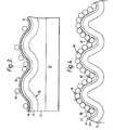
- FIGURE 3 illustrates schematically a cross-section of an article in accordance with the invention; and
- FIGURE 4 illustrates schematically a second article in accordance with the invention.
- Referring to Figures 1 and 2, a beam of light whose wavelength corresponds to the absorption wavelength of the dye molecules is incident on a diffraction grating at an angle which generates the maximum surface plasmon response. Fluorescence, at wavelength f, when present, is emitted at an angle 9f.
- The angles of absorption and emission are determined by the relationship:

When the analyte molecule is sufficiently small that binding does not measurably affect the resonance angles, the reflected power at the absorption and fluorescent wavelengths varies as a function of incident angle in the manner shown in Figures 2a and 2b. The reflected power at the absorption wavelength behaves in the usual way for plasmon resonance. The reflected power at the fluorescent wavelength increases as the amount of bound analyte increases, and the maximum in the curve occurs at the angle of incidence which excites the maximum plasmon resonance. - Referring next to Figure 3, an article in accordance with this invention is shown in the condition after it has been contacted by a sample in the method of the invention. The article comprises a
substrate 10 formed of polymethylmethacrylate which is about 1 millimeter thick. The substrate carries a polyester layer 11 which carries thepre-formed relief profile 12. The active surface of the article comprises alayer 13 of aluminium of thickness 20 nanometers which conforms, at its upper surface, torelief profile 12. This layer is covered by apassive film 14 of aluminium oxide (thickness 10 nanometers or less) which also conforms to profile 12. A monomolecular layer ofantigen molecules 15 is covalently bonded to thefilm 13 of aluminium oxide and is thus immobilised. Theantigen molecules 12 are tagged with the fluorescent dye Rhodamine B. A monomolecular discontinuous layer ofantibodies 16 is attached to theantigen layer 15. Thesubstrate 10 with thelayers antibodies 16, i.e. before contact between the article and the sample, fluorescence of the fluorochrome was strongly activated and was emitted in a narrow cone, rather than uniformly. Increasing numbers ofantibody molecules 16 result in progressive quenching of the fluorescence. - Referring next to Figure 4, there is shown part of a second type of article in accordance with this invention. The
layers Layer 17 is a bound layer of antibody molecules, to which a number ofantigen molecules 18 have become attached after contact between the article and a sample for assay. The sample containing antigen molecules 18 (analyte) was previously treated (by conventional techniques) to dye-tag themolecules 18. Because of the plasmon coupling effect described hereinbefore, fluorescence of the discontinuousmonomolecular layer 18 can be observed even when veryfew molecules 18 are present. This enables a very sensitive means of assaying theantigen molecules 18. It is possible to observe this fluorescence even in the presence of other compnents of the sample and unattached antigen molecules. - In Figure 3, the
layer 16 is monomolecular, with a coverage of about ten percent of the surface, for example. With molecules of about ten nanometers in height, this is equivalent to a mean layer thickness of about one nm.
Claims (24)
Priority Applications (1)
| Application Number | Priority Date | Filing Date | Title |
|---|---|---|---|
| AT85306577T ATE62074T1 (en) | 1984-09-14 | 1985-09-16 | METHOD AND DEVICE FOR IMMUNOLOGICAL EXAMINATION. |
Applications Claiming Priority (2)
| Application Number | Priority Date | Filing Date | Title |
|---|---|---|---|
| GB8423204 | 1984-09-14 | ||
| GB848423204A GB8423204D0 (en) | 1984-09-14 | 1984-09-14 | Assay technique and equipment |
Publications (2)
| Publication Number | Publication Date |
|---|---|
| EP0178083A1 true EP0178083A1 (en) | 1986-04-16 |
| EP0178083B1 EP0178083B1 (en) | 1991-03-27 |
Family
ID=10566693
Family Applications (1)
| Application Number | Title | Priority Date | Filing Date |
|---|---|---|---|
| EP85306577A Expired EP0178083B1 (en) | 1984-09-14 | 1985-09-16 | Assay technique and equipment |
Country Status (10)
| Country | Link |
|---|---|
| US (1) | US4882288A (en) |
| EP (1) | EP0178083B1 (en) |
| JP (1) | JPH0658370B2 (en) |
| AT (1) | ATE62074T1 (en) |
| AU (1) | AU591070B2 (en) |
| CA (1) | CA1263599A (en) |
| DE (1) | DE3582296D1 (en) |
| GB (1) | GB8423204D0 (en) |
| NO (1) | NO168273C (en) |
| WO (1) | WO1986001901A1 (en) |
Cited By (13)
| Publication number | Priority date | Publication date | Assignee | Title |
|---|---|---|---|---|
| GB2167856A (en) * | 1984-11-23 | 1986-06-04 | Human Oltoanyagtermelo | A quick-diagnostic tool for blood-grouping and process for preparing same |
| EP0266461A1 (en) * | 1986-11-03 | 1988-05-11 | The Center For Immunological Studies | Methods for the detection and quantitation of immunological substances |
| EP0276142A1 (en) * | 1987-01-21 | 1988-07-27 | ARS Holding 89 N.V. | Assay technique |
| GB2202045A (en) * | 1987-03-10 | 1988-09-14 | Pa Consulting Services | Sensors for performing assays |
| EP0350233A2 (en) * | 1988-07-05 | 1990-01-10 | Immucor, Inc. | An article for performing immunological assays utilizing organic dyes and methods for producing and utilizing same |
| EP0350073A2 (en) * | 1988-07-07 | 1990-01-10 | Adeza Biomedical Corporation | A light diffraction hybridation assay |
| AU594176B2 (en) * | 1986-07-24 | 1990-03-01 | Applied Research Systems Ars Holding N.V. | Polymer-coated optical structures |
| EP0395300A2 (en) * | 1989-04-28 | 1990-10-31 | Westaim Technologies Inc. | Thin film diagnostic device |
| EP0528988A1 (en) * | 1990-05-17 | 1993-03-03 | Adeza Biomedical Corp | Highly reflective biogratings and method. |
| EP0795752A1 (en) * | 1996-03-13 | 1997-09-17 | AVL Medical Instruments AG | Optochemical method and device to determine the concentration of an analyte |
| US6707561B1 (en) | 1999-07-05 | 2004-03-16 | Novartis Ag | Sensor platform, apparatus incorporating platform, and process using the platform |
| US6771376B2 (en) | 1999-07-05 | 2004-08-03 | Novartis Ag | Sensor platform, apparatus incorporating the platform, and process using the platform |
| CN103451086B (en) * | 2007-07-20 | 2015-03-04 | 株式会社日立高新技术 | Nucleic acid analysis device and nucleic acid analyzer using the same |
Families Citing this family (103)
| Publication number | Priority date | Publication date | Assignee | Title |
|---|---|---|---|---|
| DE3376685D1 (en) * | 1982-12-21 | 1988-06-23 | Ares Serono Nv | Assay technique |
| US4806312A (en) * | 1985-08-28 | 1989-02-21 | Miles Inc. | Multizone analytical element having detectable signal concentrating zone |
| JPS6283641A (en) * | 1985-10-08 | 1987-04-17 | Sharp Corp | Sensor element |
| CA1305921C (en) * | 1987-01-30 | 1992-08-04 | Eric K. Gustafson | Diffraction immunoassay and reagents |
| GB8705649D0 (en) * | 1987-03-10 | 1987-04-15 | Pa Consulting Services | Assay sensor |
| GB8705650D0 (en) * | 1987-03-10 | 1987-04-15 | Pa Consulting Services | Assay technique |
| US5478755A (en) * | 1988-07-25 | 1995-12-26 | Ares Serono Research & Development Ltd. | Long range surface plasma resonance immunoassay |
| US5006716A (en) * | 1989-02-22 | 1991-04-09 | Research Corporation Technologies, Inc. | Method and system for directional, enhanced fluorescence from molecular layers |
| CA2076349A1 (en) * | 1990-02-22 | 1991-08-23 | Ashraf A. Ismail | Solid-phase interferometric immunoassay system |
| EP0455067B1 (en) * | 1990-05-03 | 2003-02-26 | F. Hoffmann-La Roche Ag | Micro-optical sensor |
| DE59410197D1 (en) * | 1993-03-26 | 2002-11-21 | Hoffmann La Roche | Optical method and device for analyzing substances on sensor surfaces |
| US5552272A (en) * | 1993-06-10 | 1996-09-03 | Biostar, Inc. | Detection of an analyte by fluorescence using a thin film optical device |
| US5387525A (en) * | 1993-09-03 | 1995-02-07 | Ciba Corning Diagnostics Corp. | Method for activation of polyanionic fluorescent dyes in low dielectric media with quaternary onium compounds |
| TW350894B (en) * | 1994-08-02 | 1999-01-21 | Stylite Kogyo Co Ltd | Refractory coating components, building siding panels and the siding structure |
| US5874216A (en) | 1996-02-23 | 1999-02-23 | Ensys Environmental Products, Inc. | Indirect label assay device for detecting small molecules and method of use thereof |
| US5846843A (en) * | 1996-11-18 | 1998-12-08 | The University Of Toledo | Sensor using long range surface plasmon resonance with diffraction double-grating |
| US5776785A (en) * | 1996-12-30 | 1998-07-07 | Diagnostic Products Corporation | Method and apparatus for immunoassay using fluorescent induced surface plasma emission |
| US5841143A (en) * | 1997-07-11 | 1998-11-24 | The United States Of America As Represented By Administrator Of The National Aeronautics And Space Administration | Integrated fluorescene |
| US5955378A (en) * | 1997-08-20 | 1999-09-21 | Challener; William A. | Near normal incidence optical assaying method and system having wavelength and angle sensitivity |
| US5925878A (en) * | 1997-08-20 | 1999-07-20 | Imation Corp. | Diffraction anomaly sensor having grating coated with protective dielectric layer |
| US5994150A (en) | 1997-11-19 | 1999-11-30 | Imation Corp. | Optical assaying method and system having rotatable sensor disk with multiple sensing regions |
| US6600563B1 (en) | 1997-12-12 | 2003-07-29 | Applera Corporation | Optical resonance analysis system |
| US5986762A (en) * | 1998-06-15 | 1999-11-16 | Imation Corp. | Optical sensor having optimized surface profile |
| US6320991B1 (en) | 1998-10-16 | 2001-11-20 | Imation Corp. | Optical sensor having dielectric film stack |
| US7167615B1 (en) | 1999-11-05 | 2007-01-23 | Board Of Regents, The University Of Texas System | Resonant waveguide-grating filters and sensors and methods for making and using same |
| US8111401B2 (en) | 1999-11-05 | 2012-02-07 | Robert Magnusson | Guided-mode resonance sensors employing angular, spectral, modal, and polarization diversity for high-precision sensing in compact formats |
| US7198939B2 (en) * | 2000-01-28 | 2007-04-03 | Agilent Technologies, Inc. | Apparatus for interrogating an addressable array |
| US6951715B2 (en) | 2000-10-30 | 2005-10-04 | Sru Biosystems, Inc. | Optical detection of label-free biomolecular interactions using microreplicated plastic sensor elements |
| US7175980B2 (en) | 2000-10-30 | 2007-02-13 | Sru Biosystems, Inc. | Method of making a plastic colorimetric resonant biosensor device with liquid handling capabilities |
| US7306827B2 (en) * | 2000-10-30 | 2007-12-11 | Sru Biosystems, Inc. | Method and machine for replicating holographic gratings on a substrate |
| US7118710B2 (en) * | 2000-10-30 | 2006-10-10 | Sru Biosystems, Inc. | Label-free high-throughput optical technique for detecting biomolecular interactions |
| US7202076B2 (en) * | 2000-10-30 | 2007-04-10 | Sru Biosystems, Inc. | Label-free high-throughput optical technique for detecting biomolecular interactions |
| US7371562B2 (en) | 2000-10-30 | 2008-05-13 | Sru Biosystems, Inc. | Guided mode resonant filter biosensor using a linear grating surface structure |
| US7300803B2 (en) | 2000-10-30 | 2007-11-27 | Sru Biosystems, Inc. | Label-free methods for performing assays using a colorimetric resonant reflectance optical biosensor |
| US7875434B2 (en) | 2000-10-30 | 2011-01-25 | Sru Biosystems, Inc. | Label-free methods for performing assays using a colorimetric resonant reflectance optical biosensor |
| US7023544B2 (en) | 2000-10-30 | 2006-04-04 | Sru Biosystems, Inc. | Method and instrument for detecting biomolecular interactions |
| US7101660B2 (en) * | 2000-10-30 | 2006-09-05 | Sru Biosystems, Inc. | Method for producing a colorimetric resonant reflection biosensor on rigid surfaces |
| US7153702B2 (en) * | 2000-10-30 | 2006-12-26 | Sru Biosystems, Inc. | Label-free methods for performing assays using a colorimetric resonant reflectance optical biosensor |
| US7217574B2 (en) * | 2000-10-30 | 2007-05-15 | Sru Biosystems, Inc. | Method and apparatus for biosensor spectral shift detection |
| US7264973B2 (en) * | 2000-10-30 | 2007-09-04 | Sru Biosystems, Inc. | Label-free methods for performing assays using a colorimetric resonant optical biosensor |
| US7575939B2 (en) | 2000-10-30 | 2009-08-18 | Sru Biosystems, Inc. | Optical detection of label-free biomolecular interactions using microreplicated plastic sensor elements |
| AU2006201361B2 (en) * | 2000-10-30 | 2009-01-22 | Sru Biosystems, Inc. | A label-free high-throughput optical technique for detecting biomolecular interactions |
| US7524625B2 (en) * | 2000-10-30 | 2009-04-28 | Sru Biosystems, Inc. | Real time binding analysis of antigens on a biosensor surface |
| US7142296B2 (en) | 2000-10-30 | 2006-11-28 | Sru Biosystems, Inc. | Method and apparatus for detecting biomolecular interactions |
| US7070987B2 (en) * | 2000-10-30 | 2006-07-04 | Sru Biosystems, Inc. | Guided mode resonant filter biosensor using a linear grating surface structure |
| US7615339B2 (en) | 2000-10-30 | 2009-11-10 | Sru Biosystems, Inc. | Method for producing a colorimetric resonant reflection biosensor on rigid surfaces |
| JP3525142B2 (en) * | 2001-01-12 | 2004-05-10 | 独立行政法人 科学技術振興機構 | Fluorescence analysis element using metal nanowell and method for producing the same |
| FR2827386B1 (en) * | 2001-07-11 | 2003-10-31 | Centre Nat Rech Scient | BIOPUCE AND ITS MANUFACTURING METHOD |
| WO2003014711A1 (en) * | 2001-08-07 | 2003-02-20 | Mitsubishi Chemical Corporation | Surface plasmon resonance sensor chip, and sample analysis method and analysis apparatus using the same |
| WO2003023400A2 (en) * | 2001-09-13 | 2003-03-20 | Axela Biosensors Inc. | Method and apparatus for assay based on light diffraction |
| US7300798B2 (en) * | 2001-10-18 | 2007-11-27 | Agilent Technologies, Inc. | Chemical arrays |
| US7098041B2 (en) | 2001-12-11 | 2006-08-29 | Kimberly-Clark Worldwide, Inc. | Methods to view and analyze the results from diffraction-based diagnostics |
| US7102752B2 (en) | 2001-12-11 | 2006-09-05 | Kimberly-Clark Worldwide, Inc. | Systems to view and analyze the results from diffraction-based diagnostics |
| US6791690B2 (en) * | 2002-04-30 | 2004-09-14 | Agilent Technologies, Inc. | Reading dry chemical arrays |
| US7223368B2 (en) | 2002-05-03 | 2007-05-29 | Kimberly-Clark Worldwide, Inc. | Diffraction-based diagnostic devices |
| US7223534B2 (en) | 2002-05-03 | 2007-05-29 | Kimberly-Clark Worldwide, Inc. | Diffraction-based diagnostic devices |
| US7118855B2 (en) * | 2002-05-03 | 2006-10-10 | Kimberly-Clark Worldwide, Inc. | Diffraction-based diagnostic devices |
| US7214530B2 (en) | 2002-05-03 | 2007-05-08 | Kimberly-Clark Worldwide, Inc. | Biomolecule diagnostic devices and method for producing biomolecule diagnostic devices |
| US7485453B2 (en) * | 2002-05-03 | 2009-02-03 | Kimberly-Clark Worldwide, Inc. | Diffraction-based diagnostic devices |
| US7771922B2 (en) | 2002-05-03 | 2010-08-10 | Kimberly-Clark Worldwide, Inc. | Biomolecule diagnostic device |
| US7091049B2 (en) * | 2002-06-26 | 2006-08-15 | Kimberly-Clark Worldwide, Inc. | Enhanced diffraction-based biosensor devices |
| US7508608B2 (en) | 2004-11-17 | 2009-03-24 | Illumina, Inc. | Lithographically fabricated holographic optical identification element |
| WO2004019276A1 (en) | 2002-08-20 | 2004-03-04 | Cyvera Corporation | Diffraction grating-based optical identification element |
| US7441703B2 (en) | 2002-08-20 | 2008-10-28 | Illumina, Inc. | Optical reader for diffraction grating-based encoded optical identification elements |
| US7901630B2 (en) | 2002-08-20 | 2011-03-08 | Illumina, Inc. | Diffraction grating-based encoded microparticle assay stick |
| US7164533B2 (en) | 2003-01-22 | 2007-01-16 | Cyvera Corporation | Hybrid random bead/chip based microarray |
| US7900836B2 (en) | 2002-08-20 | 2011-03-08 | Illumina, Inc. | Optical reader system for substrates having an optically readable code |
| US7872804B2 (en) | 2002-08-20 | 2011-01-18 | Illumina, Inc. | Encoded particle having a grating with variations in the refractive index |
| US7923260B2 (en) | 2002-08-20 | 2011-04-12 | Illumina, Inc. | Method of reading encoded particles |
| US7619819B2 (en) | 2002-08-20 | 2009-11-17 | Illumina, Inc. | Method and apparatus for drug product tracking using encoded optical identification elements |
| US7927822B2 (en) * | 2002-09-09 | 2011-04-19 | Sru Biosystems, Inc. | Methods for screening cells and antibodies |
| US7429492B2 (en) | 2002-09-09 | 2008-09-30 | Sru Biosystems, Inc. | Multiwell plates with integrated biosensors and membranes |
| US7092160B2 (en) | 2002-09-12 | 2006-08-15 | Illumina, Inc. | Method of manufacturing of diffraction grating-based optical identification element |
| EP1540592A1 (en) | 2002-09-12 | 2005-06-15 | Cyvera Corporation | Method and apparatus for labeling using diffraction grating-based encoded optical identification elements |
| WO2004025561A1 (en) | 2002-09-12 | 2004-03-25 | Cyvera Corporation | Chemical synthesis using diffraction grating-based encoded optical elements |
| CA2499046A1 (en) | 2002-09-12 | 2004-03-25 | Cyvera Corporation | Diffraction grating-based encoded micro-particles for multiplexed experiments |
| WO2004024328A1 (en) | 2002-09-12 | 2004-03-25 | Cyvera Corporation | Method and apparatus for aligning elongated microbeads in order to interrogate the same |
| US20100255603A9 (en) | 2002-09-12 | 2010-10-07 | Putnam Martin A | Method and apparatus for aligning microbeads in order to interrogate the same |
| US7169550B2 (en) * | 2002-09-26 | 2007-01-30 | Kimberly-Clark Worldwide, Inc. | Diffraction-based diagnostic devices |
| US7309614B1 (en) | 2002-12-04 | 2007-12-18 | Sru Biosystems, Inc. | Self-referencing biodetection method and patterned bioassays |
| US6956221B2 (en) * | 2003-02-03 | 2005-10-18 | Agilent Technologies, Inc. | Tunable cross-coupling evanescent mode optical devices and methods of making the same |
| US7070406B2 (en) * | 2003-04-29 | 2006-07-04 | Hewlett-Packard Development Company, L.P. | Apparatus for embossing a flexible substrate with a pattern carried by an optically transparent compliant media |
| US20050053974A1 (en) * | 2003-05-20 | 2005-03-10 | University Of Maryland | Apparatus and methods for surface plasmon-coupled directional emission |
| US8298780B2 (en) | 2003-09-22 | 2012-10-30 | X-Body, Inc. | Methods of detection of changes in cells |
| EP1680679A2 (en) * | 2003-11-06 | 2006-07-19 | SRU Biosystems Inc. | High-density amine-functionalized surface |
| US7433123B2 (en) | 2004-02-19 | 2008-10-07 | Illumina, Inc. | Optical identification element having non-waveguide photosensitive substrate with diffraction grating therein |
| WO2006055736A1 (en) | 2004-11-16 | 2006-05-26 | Illumina, Inc. | And methods and apparatus for reading coded microbeads |
| WO2006055735A2 (en) | 2004-11-16 | 2006-05-26 | Illumina, Inc | Scanner having spatial light modulator |
| US7604173B2 (en) | 2004-11-16 | 2009-10-20 | Illumina, Inc. | Holographically encoded elements for microarray and other tagging labeling applications, and method and apparatus for making and reading the same |
| WO2006127167A2 (en) * | 2005-04-12 | 2006-11-30 | Sru Biosystems, Inc. | Proteolipid membrane & lipid membrane biosensor |
| US7623624B2 (en) | 2005-11-22 | 2009-11-24 | Illumina, Inc. | Method and apparatus for labeling using optical identification elements characterized by X-ray diffraction |
| WO2007072418A2 (en) * | 2005-12-22 | 2007-06-28 | Koninklijke Philips Electronics N.V. | Increasing energy density in sub-wavelength wire-grids |
| US7830575B2 (en) | 2006-04-10 | 2010-11-09 | Illumina, Inc. | Optical scanner with improved scan time |
| DE602007011651D1 (en) * | 2006-10-24 | 2011-02-10 | Koninkl Philips Electronics Nv | DETECTION OF TARGET MOLECULES BY LUMINESCENCE |
| JP2008286778A (en) * | 2007-04-16 | 2008-11-27 | National Institute Of Advanced Industrial & Technology | Microplate with periodic structure and surface plasmon exciting intensified fluorescent microscope using the same or fluorescent microplate reader |
| CA2693700A1 (en) | 2007-07-11 | 2009-01-15 | Sru Biosystems, Inc. | Methods for identifying modulators of ion channels |
| US9134307B2 (en) | 2007-07-11 | 2015-09-15 | X-Body, Inc. | Method for determining ion channel modulating properties of a test reagent |
| EP2060904A1 (en) * | 2007-11-13 | 2009-05-20 | Koninklijke Philips Electronics N.V. | Plasmon grating biosensor |
| US8257936B2 (en) | 2008-04-09 | 2012-09-04 | X-Body Inc. | High resolution label free analysis of cellular properties |
| EP2112500A1 (en) * | 2008-04-22 | 2009-10-28 | Koninklijke Philips Electronics N.V. | Plasmonic biosensor |
| US8841119B2 (en) * | 2010-07-22 | 2014-09-23 | Mridangam Research Intellectual Property Trust | Sensor for fast detection of E-coli |
| EP2827130A1 (en) * | 2013-07-15 | 2015-01-21 | F. Hoffmann-La Roche AG | Device for use in the detection of binding affinities |
| EP3948236A1 (en) | 2019-03-25 | 2022-02-09 | AIT Austrian Institute of Technology GmbH | Plasmon-enhanced fluorescence spectroscopy imaging by multi-resonant nanostructures |
Citations (3)
| Publication number | Priority date | Publication date | Assignee | Title |
|---|---|---|---|---|
| US4222743A (en) * | 1978-07-20 | 1980-09-16 | Wang Wei Kung | Method and apparatus for detecting biological particles by fluorescent stain |
| EP0112721A2 (en) * | 1982-12-21 | 1984-07-04 | Ares-Serono N.V. | Assay technique |
| EP0075353B1 (en) * | 1981-09-18 | 1987-08-19 | Battelle Memorial Institute | Method and apparatus for the determination of species in solution with an optical wave-guide |
Family Cites Families (2)
| Publication number | Priority date | Publication date | Assignee | Title |
|---|---|---|---|---|
| US4537861A (en) * | 1983-02-03 | 1985-08-27 | Elings Virgil B | Apparatus and method for homogeneous immunoassay |
| US4647544A (en) * | 1984-06-25 | 1987-03-03 | Nicoli David F | Immunoassay using optical interference detection |
-
1984
- 1984-09-14 GB GB848423204A patent/GB8423204D0/en active Pending
-
1985
- 1985-09-16 AU AU48062/85A patent/AU591070B2/en not_active Expired
- 1985-09-16 EP EP85306577A patent/EP0178083B1/en not_active Expired
- 1985-09-16 JP JP60504123A patent/JPH0658370B2/en not_active Expired - Lifetime
- 1985-09-16 US US07/866,080 patent/US4882288A/en not_active Expired - Lifetime
- 1985-09-16 DE DE8585306577T patent/DE3582296D1/en not_active Expired - Lifetime
- 1985-09-16 AT AT85306577T patent/ATE62074T1/en not_active IP Right Cessation
- 1985-09-16 WO PCT/GB1985/000427 patent/WO1986001901A1/en unknown
- 1985-09-16 CA CA000490845A patent/CA1263599A/en not_active Expired
-
1986
- 1986-05-13 NO NO86861912A patent/NO168273C/en not_active IP Right Cessation
Patent Citations (3)
| Publication number | Priority date | Publication date | Assignee | Title |
|---|---|---|---|---|
| US4222743A (en) * | 1978-07-20 | 1980-09-16 | Wang Wei Kung | Method and apparatus for detecting biological particles by fluorescent stain |
| EP0075353B1 (en) * | 1981-09-18 | 1987-08-19 | Battelle Memorial Institute | Method and apparatus for the determination of species in solution with an optical wave-guide |
| EP0112721A2 (en) * | 1982-12-21 | 1984-07-04 | Ares-Serono N.V. | Assay technique |
Non-Patent Citations (3)
| Title |
|---|
| CLINICAL CHEMISTRY, vol. 25, no. 3, 1979, pages 353-361; E. SOINI et al.: "Fluoroimmunoassay: present status and key problems" * |
| OPTICS LETTERS, vol. 5, no. 9, September 1980, pages 368-370, Optical Society of America, US; A.M. GLASS et al.: "Interaction of metal particles with adsorbed dye molecules: absorption and luminescence" * |
| OPTICS LETTERS, vol. 7, no. 2, February 1982, pages 89-91, Optical Society of America, US; D.A. WEITZ et al.: "Fluorescent lifetimes of molecules on silver-island films" * |
Cited By (26)
| Publication number | Priority date | Publication date | Assignee | Title |
|---|---|---|---|---|
| GB2167856A (en) * | 1984-11-23 | 1986-06-04 | Human Oltoanyagtermelo | A quick-diagnostic tool for blood-grouping and process for preparing same |
| AU594176B2 (en) * | 1986-07-24 | 1990-03-01 | Applied Research Systems Ars Holding N.V. | Polymer-coated optical structures |
| US4992385A (en) * | 1986-07-24 | 1991-02-12 | Ares-Serono Research And Development Limited Partnership | Polymer-coated optical structures and methods of making and using the same |
| EP0266461A1 (en) * | 1986-11-03 | 1988-05-11 | The Center For Immunological Studies | Methods for the detection and quantitation of immunological substances |
| US6093536A (en) * | 1987-01-21 | 2000-07-25 | Ares-Serono Research & Development Limited Partnership | Wood's anomaly assay technique and kit |
| EP0276142A1 (en) * | 1987-01-21 | 1988-07-27 | ARS Holding 89 N.V. | Assay technique |
| GB2202045A (en) * | 1987-03-10 | 1988-09-14 | Pa Consulting Services | Sensors for performing assays |
| GB2202045B (en) * | 1987-03-10 | 1991-08-21 | Pa Consulting Services | Improvements relating to sensors for performing assays |
| US5468618A (en) * | 1988-07-05 | 1995-11-21 | Immucor, Inc. | Article for performing immunological assays utilizing organic dyes to immobilize immunologically reactive components to a solid phase support and methods for producing and utilizing same |
| EP0350233A2 (en) * | 1988-07-05 | 1990-01-10 | Immucor, Inc. | An article for performing immunological assays utilizing organic dyes and methods for producing and utilizing same |
| EP0350233A3 (en) * | 1988-07-05 | 1990-11-22 | Immucor, Inc. | An article for performing immunological assays utilizing organic dyes and methods for producing and utilizing same |
| EP0350073A3 (en) * | 1988-07-07 | 1991-09-04 | Adeza Biomedical Corporation | A light diffraction hybridation assay |
| EP0350073A2 (en) * | 1988-07-07 | 1990-01-10 | Adeza Biomedical Corporation | A light diffraction hybridation assay |
| EP0395300A2 (en) * | 1989-04-28 | 1990-10-31 | Westaim Technologies Inc. | Thin film diagnostic device |
| EP0395300A3 (en) * | 1989-04-28 | 1992-10-14 | Westaim Technologies Inc. | Thin film diagnostic device |
| EP0528988A1 (en) * | 1990-05-17 | 1993-03-03 | Adeza Biomedical Corp | Highly reflective biogratings and method. |
| EP0528988A4 (en) * | 1990-05-17 | 1994-04-13 | Adeza Biomedical Corporation | |
| US5478527A (en) * | 1990-05-17 | 1995-12-26 | Adeza Biomedical Corporation | Highly reflective biogratings |
| EP0795752A1 (en) * | 1996-03-13 | 1997-09-17 | AVL Medical Instruments AG | Optochemical method and device to determine the concentration of an analyte |
| US6707561B1 (en) | 1999-07-05 | 2004-03-16 | Novartis Ag | Sensor platform, apparatus incorporating platform, and process using the platform |
| US6771376B2 (en) | 1999-07-05 | 2004-08-03 | Novartis Ag | Sensor platform, apparatus incorporating the platform, and process using the platform |
| US6867869B2 (en) | 1999-07-05 | 2005-03-15 | Novartis Ag | Sensor platform, apparatus incorporating the platform, and process using the platform |
| US6870630B2 (en) | 1999-07-05 | 2005-03-22 | Novartis Ag | Sensor platform, apparatus incorporating the platform, and process using the same |
| US7064844B2 (en) | 1999-07-05 | 2006-06-20 | Novartis Ag | Sensor platform, apparatus incorporating the platform and process using the platform |
| US7820106B2 (en) | 1999-07-05 | 2010-10-26 | Novartis Ag | Sensor platform, apparatus incorporating the platform and process using the platform |
| CN103451086B (en) * | 2007-07-20 | 2015-03-04 | 株式会社日立高新技术 | Nucleic acid analysis device and nucleic acid analyzer using the same |
Also Published As
| Publication number | Publication date |
|---|---|
| DE3582296D1 (en) | 1991-05-02 |
| NO168273B (en) | 1991-10-21 |
| AU591070B2 (en) | 1989-11-30 |
| EP0178083B1 (en) | 1991-03-27 |
| NO168273C (en) | 1992-01-29 |
| JPS62500736A (en) | 1987-03-26 |
| US4882288A (en) | 1989-11-21 |
| WO1986001901A1 (en) | 1986-03-27 |
| GB8423204D0 (en) | 1984-10-17 |
| ATE62074T1 (en) | 1991-04-15 |
| CA1263599A (en) | 1989-12-05 |
| AU4806285A (en) | 1986-04-08 |
| JPH0658370B2 (en) | 1994-08-03 |
| NO861912L (en) | 1986-07-08 |
Similar Documents
| Publication | Publication Date | Title |
|---|---|---|
| AU591070B2 (en) | Assay technique and equipment | |
| EP0760944B1 (en) | Process for detecting evanescently excited luminescence | |
| EP0167335B1 (en) | Method of detecting binding reaction between ligand and anti-ligand | |
| US4368047A (en) | Process for conducting fluorescence immunoassays without added labels and employing attenuated internal reflection | |
| EP0824684B1 (en) | Method for the parallel detection of a plurality of analytes using evanescently excited luminescence | |
| CA2120481C (en) | Assay system | |
| JP2625098B2 (en) | Method and apparatus for detecting sample using electromagnetic signal | |
| US5026159A (en) | Area-modulated luminescence (AML) | |
| EP0519623A2 (en) | Multiple surface evanescent wave sensor system | |
| EP0677734A2 (en) | Detection of a target substance in a sample | |
| US20080038835A1 (en) | Reference Member for Fluorescence Measurements, and Method for the Production Thereof | |
| JP6606509B2 (en) | Bioassay system and method for detecting analyte in body fluid | |
| EP0115532A1 (en) | Immunoassay apparatus and methods | |
| JP2002502967A (en) | Method and apparatus for measuring luminescence | |
| WO1988007202A1 (en) | Improved assay technique and apparatus therefor | |
| US5891658A (en) | Single-step, solid-state competitive immunoassay | |
| JPH0795036B2 (en) | Quantitative measurement of chemical parameters of samples | |
| EP0731916A1 (en) | Ultrasensitive competitive immunoassays using optical waveguides | |
| JP2005077396A (en) | Optical waveguide for analysis | |
| JPH02254364A (en) | Plate for measuring immunity of biological/chemical luminescent enzyme | |
| WO1993010266A1 (en) | Device and method for detection of compounds which intercalate with nucleic acids | |
| Daneshvar et al. | Investigation of a near-infrared fiber optic immunosensor | |
| FI104586B (en) | Method of monitoring a bioaffinity reaction in realtime |
Legal Events
| Date | Code | Title | Description |
|---|---|---|---|
| PUAI | Public reference made under article 153(3) epc to a published international application that has entered the european phase |
Free format text: ORIGINAL CODE: 0009012 |
|
| AK | Designated contracting states |
Kind code of ref document: A1 Designated state(s): AT BE CH DE FR GB IT LI LU NL SE |
|
| 17P | Request for examination filed |
Effective date: 19860519 |
|
| RAP1 | Party data changed (applicant data changed or rights of an application transferred) |
Owner name: ARES-SERONO N.V. |
|
| RIN1 | Information on inventor provided before grant (corrected) |
Inventor name: SAWYERS, CRAIG GEORGE Inventor name: PETTY-SAPHON, SATHAM Inventor name: NORTH, JOHN ROBERT |
|
| 17Q | First examination report despatched |
Effective date: 19880620 |
|
| ITF | It: translation for a ep patent filed |
Owner name: ING. ZINI MARANESI & C. S.R.L. |
|
| GRAA | (expected) grant |
Free format text: ORIGINAL CODE: 0009210 |
|
| AK | Designated contracting states |
Kind code of ref document: B1 Designated state(s): AT BE CH DE FR GB IT LI LU NL SE |
|
| REF | Corresponds to: |
Ref document number: 62074 Country of ref document: AT Date of ref document: 19910415 Kind code of ref document: T |
|
| REF | Corresponds to: |
Ref document number: 3582296 Country of ref document: DE Date of ref document: 19910502 |
|
| ET | Fr: translation filed | ||
| PLBE | No opposition filed within time limit |
Free format text: ORIGINAL CODE: 0009261 |
|
| STAA | Information on the status of an ep patent application or granted ep patent |
Free format text: STATUS: NO OPPOSITION FILED WITHIN TIME LIMIT |
|
| 26N | No opposition filed | ||
| REG | Reference to a national code |
Ref country code: GB Ref legal event code: 732E |
|
| ITPR | It: changes in ownership of a european patent |
Owner name: CESSIONE;APPLIED RESEARCH SYSTEMS ARS HOLDINGS N.V |
|
| REG | Reference to a national code |
Ref country code: CH Ref legal event code: PUE Owner name: APPLIED RESEARCH SYSTEMS ARS HOLDING N.V. |
|
| REG | Reference to a national code |
Ref country code: FR Ref legal event code: TP |
|
| NLS | Nl: assignments of ep-patents |
Owner name: APPLIED RESEARCH SYSTEMS ARS HOLDING N.V. TE WILLE |
|
| EPTA | Lu: last paid annual fee | ||
| EAL | Se: european patent in force in sweden |
Ref document number: 85306577.9 |
|
| REG | Reference to a national code |
Ref country code: CH Ref legal event code: PFA Free format text: APPLIED RESEARCH SYSTEMS ARS HOLDING N.V.,6 JOHN B. GORSIRAWEG,CURACAO (AN) TRANSFER- APPLIED RESEARCH SYSTEMS ARS HOLDING N.V.,14 JOHN B. GORSIRAWEG,CURACAO (AN) |
|
| REG | Reference to a national code |
Ref country code: GB Ref legal event code: IF02 |
|
| PGFP | Annual fee paid to national office [announced via postgrant information from national office to epo] |
Ref country code: NL Payment date: 20040905 Year of fee payment: 20 |
|
| PGFP | Annual fee paid to national office [announced via postgrant information from national office to epo] |
Ref country code: SE Payment date: 20040906 Year of fee payment: 20 |
|
| PGFP | Annual fee paid to national office [announced via postgrant information from national office to epo] |
Ref country code: FR Payment date: 20040908 Year of fee payment: 20 |
|
| PGFP | Annual fee paid to national office [announced via postgrant information from national office to epo] |
Ref country code: DE Payment date: 20040909 Year of fee payment: 20 |
|
| PGFP | Annual fee paid to national office [announced via postgrant information from national office to epo] |
Ref country code: LU Payment date: 20040913 Year of fee payment: 20 Ref country code: AT Payment date: 20040913 Year of fee payment: 20 |
|
| PGFP | Annual fee paid to national office [announced via postgrant information from national office to epo] |
Ref country code: GB Payment date: 20040915 Year of fee payment: 20 Ref country code: CH Payment date: 20040915 Year of fee payment: 20 |
|
| PGFP | Annual fee paid to national office [announced via postgrant information from national office to epo] |
Ref country code: BE Payment date: 20041122 Year of fee payment: 20 |
|
| PG25 | Lapsed in a contracting state [announced via postgrant information from national office to epo] |
Ref country code: GB Free format text: LAPSE BECAUSE OF EXPIRATION OF PROTECTION Effective date: 20050915 |
|
| PG25 | Lapsed in a contracting state [announced via postgrant information from national office to epo] |
Ref country code: NL Free format text: LAPSE BECAUSE OF EXPIRATION OF PROTECTION Effective date: 20050916 |
|
| BE20 | Be: patent expired |
Owner name: *APPLIED RESEARCH SYSTEMS ARS HOLDINGS N.V. Effective date: 20050916 |
|
| REG | Reference to a national code |
Ref country code: GB Ref legal event code: PE20 |
|
| REG | Reference to a national code |
Ref country code: CH Ref legal event code: PL |
|
| EUG | Se: european patent has lapsed | ||
| NLV7 | Nl: ceased due to reaching the maximum lifetime of a patent |
Effective date: 20050916 |
|
| BE20 | Be: patent expired |
Owner name: *APPLIED RESEARCH SYSTEMS ARS HOLDINGS N.V. Effective date: 20050916 |