EP0178377A2 - Tube-like container - Google Patents
Tube-like container Download PDFInfo
- Publication number
- EP0178377A2 EP0178377A2 EP85105867A EP85105867A EP0178377A2 EP 0178377 A2 EP0178377 A2 EP 0178377A2 EP 85105867 A EP85105867 A EP 85105867A EP 85105867 A EP85105867 A EP 85105867A EP 0178377 A2 EP0178377 A2 EP 0178377A2
- Authority
- EP
- European Patent Office
- Prior art keywords
- outlet
- tube container
- tube
- distributor
- container according
- Prior art date
- Legal status (The legal status is an assumption and is not a legal conclusion. Google has not performed a legal analysis and makes no representation as to the accuracy of the status listed.)
- Withdrawn
Links
Images
Classifications
-
- B—PERFORMING OPERATIONS; TRANSPORTING
- B65—CONVEYING; PACKING; STORING; HANDLING THIN OR FILAMENTARY MATERIAL
- B65D—CONTAINERS FOR STORAGE OR TRANSPORT OF ARTICLES OR MATERIALS, e.g. BAGS, BARRELS, BOTTLES, BOXES, CANS, CARTONS, CRATES, DRUMS, JARS, TANKS, HOPPERS, FORWARDING CONTAINERS; ACCESSORIES, CLOSURES, OR FITTINGS THEREFOR; PACKAGING ELEMENTS; PACKAGES
- B65D35/00—Pliable tubular containers adapted to be permanently or temporarily deformed to expel contents, e.g. collapsible tubes for toothpaste or other plastic or semi-liquid material; Holders therefor
- B65D35/24—Pliable tubular containers adapted to be permanently or temporarily deformed to expel contents, e.g. collapsible tubes for toothpaste or other plastic or semi-liquid material; Holders therefor with auxiliary devices
- B65D35/36—Pliable tubular containers adapted to be permanently or temporarily deformed to expel contents, e.g. collapsible tubes for toothpaste or other plastic or semi-liquid material; Holders therefor with auxiliary devices for applying contents to surfaces
- B65D35/38—Nozzles
Definitions
- the invention relates to a tube container for extrudable coating material.
- Tube containers are traditionally known as storage and processing containers for extrudable spreadable materials of the most varied types, for example for toothpaste, for pharmaceutical and cosmetic preparations of the most varied types in cream or paste form, and furthermore for spreadable materials for technical-commercial purposes such as adhesives, putties, plastic materials , Colors, etc., and finally also for foods such as mustard, horseradish, mayonnaise, meat and liver pies and the like.
- Tube containers of this type usually have on their outlet end side an outlet device which can be closed with a screw cap and which usually has a substantially circular outlet opening of a diameter which is substantially smaller than the tube diameter.
- the invention relates to a tube container which is particularly suitable for dispensing spreadable contents in a relatively wide strand shape, which allows the spreadable spread to be conveniently distributed in a wide strand.
- the invention is intended to create a tube container for spreadable cheese and food or luxury goods of comparable consistency, which is suitable for garnishing purposes, for example garnishing pizzas or the like with cheese.
- the preparation of spreadable cheese in tube form is new as such and in the form of a tube container particularly suitable for this purpose the subject of the present invention.
- the invention thus relates to a tube container for extrudable spreadable material, in particular for spreadable cheese or food of comparable consistency, with an outlet device which can be closed with a screw cap and is provided on the outlet end of the tube container.
- the invention is intended to create a tube container of this type which is particularly, although not exclusively, suitable for spreadable material in the food and foodstuffs field, in particular for the aforementioned new cheese packaging in tube form, and the adjustment of the contents of the tube in the form of a ribbon-shaped strand the preferred applications of the spread, such as for garnishing pizzas or the like with cheese.
- the tube container is supposed to be easy to apply while being simple and inexpensive to produce Ensure supply in the form of a ribbon-shaped strand which is as far as possible adapted to the respective type of application, while at the same time ensuring hygienic storage and storage before and after opening the tube until the tube contents have been completely used up.
- the outlet device is designed as an outlet spreading distributor in order to achieve an extrusion strand of the coating material which is suitable in terms of shape and dimension, the provision being made in accordance with the preferred embodiment that the outlet - Spreading distributor consists of a base part inserted into or connected to the end wall and an outlet nozzle part with an end-side outlet opening adjoining the end wall, and that the outlet-spreading distributor, at least in its cross-sectional configuration in the sectional plane perpendicular to the main dimension, has a rounded gradual transition from the relatively larger dimension in the lower part to the relatively smaller transverse dimension of the outlet opening in the upper part.
- the outlet spreading distributor is formed in one piece and can either be inserted into the end wall of the tube container or is also formed in one piece with the end wall of the tube container.
- a particularly preferred configuration for food or foodstuffs applications, in particular also for cheese Tung is characterized by a tear-off closure over the outlet opening on the upper end face, this A tear closure as a molded on the end face of the outlet nozzle part, can be formed with this as a one-piece injection molded body.
- the tear-off closure can be designed with a grip tab protruding beyond the outlet end face of the coating distributor. After removing the screw cap, the tear-off fastener can be gripped easily by right and left-handers using the protruding grip tab.
- the tear-off seal serves as a factory-side hermetic seal for the outlet opening and guarantees a hermetic seal of the tube contents from the factory filling process until the consumer tears it off when the tube is opened for the first time. The tight reclosure of the outlet opening when the tube contents are not completely used is ensured by screwing on the screw cap, which with its bottom wall fits tightly against the end face of the outlet nozzle body when the screw connection is fully tightened, with reliable closure
- the tube container design according to the invention with an outlet spreading distributor is, as stated, particularly suitable for the novel packaging of spreadable cheese in tube form; However, it is not limited to this specific application, but is also suitable for other foodstuffs or semi-luxury goods such as mayonnaise, chocolate and cake icing, etc., and for tube masses beyond the food sector.
- the tube container designated as a whole by 1
- the tube container has at its outlet-side end 2 a coating outlet distributor, designated as a whole by 3, according to the invention, with which a screw cap 4 can be screwed in a conventional manner.
- the tube container is a cheese tube for a new kind of preparation of spreadable cheese of corresponding consistency, which is particularly suitable for cheese applications for baking, garnishing, refining or simply as a spread.
- the invention is not restricted to this special application for cheese tubes, but rather is suitable for use in tube containers for any coating material.
- the outlet spreading distributor 3 is preferably designed as a one-piece plastic injection-molded part and, in a manner known per se, is inserted into a corresponding opening 5 in the outlet-side end wall 6 of the tube container (which is slightly conical in the usual way).
- the outlet spreading distributor 3 has a base part 8 provided with an external thread 7 for the screw cap 4 and an outlet nozzle part 9 connected to the end of this. In the exemplary embodiment shown, this has an upwardly tapering parallelepiped shape with a cross section adapted to the particular application and the strand shape desired for the coating material, and has the actual outlet opening 10 for the coating material on its upper end face.
- a tear-off tab 11 projecting beyond the end face is preferably formed in one piece.
- the exit opening 10, like the horizontal cross section of the nozzle part 9, has a configuration corresponding to the shape desired for the exit strand of the coating material;
- the outlet opening 10 is essentially rectangular in shape with dimensions corresponding to the width and thickness desired for the outlet strand of the coating material.
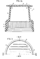
- FIGS. 2a and 2b show sectional or partial sectional views according to FIGS. 2a and 2b, of which FIG. 2a shows a (sectional) side view looking towards the broad side, and FIG. 2b shows a (partially sectioned) side view looking towards the narrow side of the coating distributor assembly.
- the tear-off 11 has, ig in particular from the F. 2a and 2b as well as from the top view of FIG. 3, a grip edge 13 with ribbing 14 on the top and bottom sides protruding sufficiently on three sides of the end face of the nozzle part 9. This grip edge protruding on three sides ensures comfortable handling for both left and right-handers to tear off the tab 11 when the tube is first opened by the consumer.
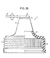
- FIG 3 shows a partial top view of the tear-off closure 11 with the grip edge 13 and the outlet opening 10 (indicated by dashed lines) underneath.
- the tear-off closure 11 with grip edge 13 integrated with the outlet nozzle body 9 is preferably formed as an injection-molded part made in one piece with the nozzle body 9, the connection to the end face of the outlet nozzle body 9 to ensure easy tear-off (with simultaneous hermetic sealing of the outlet opening), for example by one the closed web surrounding the outlet opening can be formed.
- the tear-off tab thus forms a hermetic seal on the outlet side of the tube until it is torn off by the consumer when the tube is opened for the first time.
- the external thread section 7 extends axially / downwards to ensure that when the cap is screwed on again in spite of the now lacking material thickness of the tear-off closure 11, the bottom 16 of the closure cap 4 is pressed tightly against the end face of the outlet nozzle body 9 when fully screwed on.
- the outlet spreading distributor could also be formed in one piece with this tube end wall 6, for example as a one-piece plastic part or possibly also in a metal design.
- the configuration of the outlet opening and the shape of the nozzle part 9 adapted to it there are of course the most varied possible modifications depending on the particularities of the respective coating material and the particular purposes of use.
- an oval shape or a shape as a narrow slot with a transverse dimension that is significantly smaller than the longitudinal dimension could also be provided.
- the peripheral edge of the outlet opening 10 could optionally be serrated or corrugated to achieve a corresponding surface structure of the pressed strand of coated material, be it for decorative purposes (for example for garnishing) or for technical purposes in the narrower sense, for example to enlarge the surface of the extruded strand or for additional work the pressed-S treichgutes.
- the tear-off tab 11 is designed as a swivel flap closure, which is not torn off completely when the tube is broken open, but rather is left connected along a swivel connecting edge 15 to the outlet nozzle body, for example in the one shown in FIG. 1 (or an even more retracted one) Position to be able to be folded back onto the face of the outlet nozzle body after use of the tube and incomplete use of the tube contents.
- the hinged closure 11 would then be pressed firmly against the outlet end face through the bottom wall 16 of the closure cap 4 as an additional sealing element.
Abstract
Description
Die Erfindung betrifft einen Tubenbehälter für strangpreßfähiges Streichgut.The invention relates to a tube container for extrudable coating material.
Tubenbehälter sind traditionell als Aufbewahrungs- und Verarbeitungsbehälter für strangpreßfähiges Streichgut der verschiedensten Art bekannt, beispielsweise für Zahnpaste, für pharmazeutische und kosmetische Präparate der verschiedensten Art in Creme- bzw. Pastenform, des weiteren für Streichgut für technisch-gewerbliche Zwecke wie Kleber, Kitte, Kunststoffmassen, Farben usw., sowie schließlich auch bereits für Nahrungsmittel, etwa Senf, Meerrettich, Mayonnaisen, Fleisch- und Leberpasteten und dergleichen.Tube containers are traditionally known as storage and processing containers for extrudable spreadable materials of the most varied types, for example for toothpaste, for pharmaceutical and cosmetic preparations of the most varied types in cream or paste form, and furthermore for spreadable materials for technical-commercial purposes such as adhesives, putties, plastic materials , Colors, etc., and finally also for foods such as mustard, horseradish, mayonnaise, meat and liver pies and the like.
Derartige Tubenbehälter weisen üblicherweise an ihrer Austrittsstirnseite eine mit Schraubverschlußkappe verschließbare Austrittsvorrichtung mit einer üblicherweise im wesentlichen kreisrunden Austrittsöffnung von gegenüber dem Tubendurchmesser wesentlich kleinerem Durchmesser auf.Tube containers of this type usually have on their outlet end side an outlet device which can be closed with a screw cap and which usually has a substantially circular outlet opening of a diameter which is substantially smaller than the tube diameter.
Gegenstand der Erfindung ist ein Tubenbehälter, der sich insbesondere zur Ausbringung von streichfähigem Inhalt in einer verhältnismäßig breiten Strangform eignet, der die bequeme Verteilung des Streichgutes in einem breiten Strang gestattet. Insbesondere soll durch die Erfindung ein Tubenbehälter für Streichkäse und Nahrungs- oder Genußmittel vergleichbarer Konsistenz geschaffen werden, der sich für Zwecke der Garnierung, beispielsweise der Garnierung von Pizzen oder dergleichen mit Käse, eignet.The invention relates to a tube container which is particularly suitable for dispensing spreadable contents in a relatively wide strand shape, which allows the spreadable spread to be conveniently distributed in a wide strand. In particular, the invention is intended to create a tube container for spreadable cheese and food or luxury goods of comparable consistency, which is suitable for garnishing purposes, for example garnishing pizzas or the like with cheese.
Die Konfektionierung von Streichkäse in Tubenform ist als solche neu und in Form eines hierfür besonders geeigneten Tubenbehälters Gegenstand des vorliegenden Erfindung rens.The preparation of spreadable cheese in tube form is new as such and in the form of a tube container particularly suitable for this purpose the subject of the present invention.
Die Erfindung betrifft somit einen Tubenbehälter für strangpreßfähiges Streichgut, insbesondere für Streichkäse oder Nahrungsmittel vergleichbarer Konsistenz, mit einer mit Schraubverschlußkappe verschließbaren, an der Austrittsstirnseite des Tubenbehälters vorgesehenen Austrittsvorrichtung.The invention thus relates to a tube container for extrudable spreadable material, in particular for spreadable cheese or food of comparable consistency, with an outlet device which can be closed with a screw cap and is provided on the outlet end of the tube container.
Durch die Erfindung soll ein Tubenbehälter dieser Art geschaffen werden, der sich insbesondere, wenngleich nicht ausschließlich, für Streichgut auf dem Nahrungs- und Lebensmittelgebiet, insbesondere für die erwähnte neue Käsekonfektionierung in Tubenform eignet und die Ausbringung des Tubeninhalts in Gestalt eines bandförmigen Strangs in Anpassung an die bevorzugten Anwendungsarten des Streichgutes, etwa zum Garnieren von Pizzen oder dergleichen mit Käse eignet. Der Tubenbehälter soll bei einfacher und billiger Herstellbarkeit die bequeme Ausbringung in Gestalt eines der jeweiligen Anwendungsart möglichst weitgehend angepaßten bandförmigen Strangs gewährleisten, bei gleichzeitiger Sicherstellung einer hygienischen Aufbewahrung und Lagerung vor und nach dem.Anbruch der Tube bis zum vollständigen Verbrauch des Tubeninhalts.The invention is intended to create a tube container of this type which is particularly, although not exclusively, suitable for spreadable material in the food and foodstuffs field, in particular for the aforementioned new cheese packaging in tube form, and the adjustment of the contents of the tube in the form of a ribbon-shaped strand the preferred applications of the spread, such as for garnishing pizzas or the like with cheese. The tube container is supposed to be easy to apply while being simple and inexpensive to produce Ensure supply in the form of a ribbon-shaped strand which is as far as possible adapted to the respective type of application, while at the same time ensuring hygienic storage and storage before and after opening the tube until the tube contents have been completely used up.
Zu diesem Zweck ist bei einem Tubenbehälter der vorstehend genannten Art gemäß der Erfindung vorgesehen, daß die Austrittsvorrichtung als Austritts-Streichverteiler zur Erzielung eines nach Form und Abmessung dem Verwendungszweck entsprechenden Auspreßstrangs des Streichguts ausgebildet ist, wobei gemäß der bevorzugten Ausführungsform vorgesehen ist, daß der Austritts-Streichverteiler aus einem in die Stirnwandung eingesetzten bzw. mit dieser verbundenen Sockelteil und einem an diese stirnseitig anschließenden Austrittsdüsenteil mit stirnseitiger Austrittsöffnung besteht und daß der Austritts-Streichverteiler wenigstens in seiner Querschnittskonfiguration in der zur Hauptabmessung senkrechten Schnittebene einen abgerundeten allmählichen Übergang von der verhältnismäßig größeren Abmessung im Unterteil zu der verhältnismäßig kleineren Quer-Abmessung der Austrittsöffnung im Oberteil aufweist.For this purpose, it is provided in a tube container of the aforementioned type according to the invention that the outlet device is designed as an outlet spreading distributor in order to achieve an extrusion strand of the coating material which is suitable in terms of shape and dimension, the provision being made in accordance with the preferred embodiment that the outlet - Spreading distributor consists of a base part inserted into or connected to the end wall and an outlet nozzle part with an end-side outlet opening adjoining the end wall, and that the outlet-spreading distributor, at least in its cross-sectional configuration in the sectional plane perpendicular to the main dimension, has a rounded gradual transition from the relatively larger dimension in the lower part to the relatively smaller transverse dimension of the outlet opening in the upper part.
Nach zweckmäßigen Ausgestaltungen kann vorgesehen sein, daß der Austritts-Streichverteiler einstückig ausgebildet und entweder in die Stirnwandung des Tubenbehälters einsetzbar oder auch einstückig mit der Stirnwandung des Tubenbehälters ausgebildet ist.According to expedient configurations, it can be provided that the outlet spreading distributor is formed in one piece and can either be inserted into the end wall of the tube container or is also formed in one piece with the end wall of the tube container.
Eine für Nahrungs- bzw. Lebensmittel-Anwendungen, insbesonbesondere auch für Käse, besonders bevorzugte Ausgestaltung kennzeichnet sich durch einen Abreißverschluß über der Austrittsöffnung an der oberen Stirnseite, wobei dieser Abreißverschluß als an der Stirnseite des Austrittsdüsenteils angeformter, mit diesem als einstückiger Spritzgußkörper herstellbar, ausgebildet sein kann. Der Abreißverschluß kann mit einer über die Austrittsstirnseite des Streichverteilers herausragenden Grifflasche ausgebildet sein. Nach Abnahme der Schraubverschlußkappe ist der Abreißverschluß mittels der überstehenden Grifflasche für Rechts-und Linkshänder zum Abreißen bequem faßbar. Der Abreißverschluß dient als fabrikseitiger Hermetikverschluß der Austrittsöffnung und garantiert einen hermetischen Verschluß des Tubeninhalts ab dem fabrikseitigen Einfüllvorgang bis zum Abreißen durch den Verbraucher beim erstmaligen Anbruch der Tube. Der dichte Wiederverschluß der Austrittsöffnung bei nicht vollständigem Verbrauch des Tubeninhalts wird durch Aufschrauben der Schraubverschlußkappe gewährleistet, die sich mit ihrer Bodenwandung beim vollständigen Anziehen der Verschraubung dichtschließend gegen die Stirnseite des Austrittsdüsenkörpers unter zuverlässigem Verschluß der Austrittsöffnung anlegt.A particularly preferred configuration for food or foodstuffs applications, in particular also for cheese Tung is characterized by a tear-off closure over the outlet opening on the upper end face, this A tear closure as a molded on the end face of the outlet nozzle part, can be formed with this as a one-piece injection molded body. The tear-off closure can be designed with a grip tab protruding beyond the outlet end face of the coating distributor. After removing the screw cap, the tear-off fastener can be gripped easily by right and left-handers using the protruding grip tab. The tear-off seal serves as a factory-side hermetic seal for the outlet opening and guarantees a hermetic seal of the tube contents from the factory filling process until the consumer tears it off when the tube is opened for the first time. The tight reclosure of the outlet opening when the tube contents are not completely used is ensured by screwing on the screw cap, which with its bottom wall fits tightly against the end face of the outlet nozzle body when the screw connection is fully tightened, with reliable closure of the outlet opening.
Die erfindungsgemäße Tubenbehälter-Ausbildung mit Austritts- Streichverteiler eignet sich wie dargelegt insbesondere für die neuartige Konfektionierung von Streichkäse in Tubenform; sie ist jedoch nicht auf diesen konkreten Anwendungszweck beschränkt, sondern eignet sich auch für anderes Nahrungs- bzw. Genußmittelstreichgut wie Mayonnaise, Schokoladen- und Tortenguß usw., sowie für Tubenmassen über den Nahrungssektor hinaus.The tube container design according to the invention with an outlet spreading distributor is, as stated, particularly suitable for the novel packaging of spreadable cheese in tube form; However, it is not limited to this specific application, but is also suitable for other foodstuffs or semi-luxury goods such as mayonnaise, chocolate and cake icing, etc., and for tube masses beyond the food sector.
Nachfolgend wird die Erfindung anhand der Zeichnung näher erläutert; in dieser zeigen
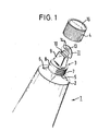
- - Fig. 1 in schematischer perspektivischer Ansicht den oberen Teil einer neuerungsgemäßen Käsetube, wobei die Schraubverschlußkappe abgenommen und die Hermetikverschluß-Abreißlasche halb abgerissen und nach oben geklappt dargestellt ist, um die Austrittsöffnung sichtbar zu machen,
- - die Figg. 2a und 2b in (geschnittener bzw. teilweise geschnittener) Seitenansicht den Austritts-Streichverteiler mit Schwenkklappenverschluß gemäß der Erfindung (wobei die Schnittebene in Figur 2a der
Linie 2A-2A inFigur 3, und die Schnittebene in Figur 2b derLinie 2B-2B inFigur 3 entspricht), - - Fig. 3 eine Teildraufsicht auf die Stirnseite des Streichverteilers mit der nicht-abgerissenen Abreißlasche für den hermetischen Verschluß der Austrittsöffnung.
- 1 is a schematic perspective view of the upper part of a cheese tube according to the innovation, the screw cap being removed and the hermetic seal tear-off tab being half-torn and shown folded up to make the outlet opening visible,
- - the fig. 2a and 2b in (cut or partially cut) side view of the outlet spreading distributor with swivel flap closure according to the invention (the section plane in FIG. 2a of the
line 2A-2A in FIG. 3 and the section plane in FIG. 2b of theline 2B-2B in FIG 3 corresponds), - - Fig. 3 is a partial plan view of the front of the spreading device with the non-torn tear-off tab for the hermetic closure of the outlet opening.
Wie aus der schematisierten perspektivischen Ansicht von Figur 1 ersichtlich, weist der als Ganzes mit 1 bezeichnete Tubenbehälter an seinem austrittsseitigen Stirnende 2 einen als Ganzes mit 3 bezeichneten Streich-Austrittsverteiler gemäß der Erfindurgauf, mit welchem in herkömmlicher Weise eine Verschlußschraubkappe 4 verschraubbar ist. Im gezeigten und beschriebenen speziellen Ausführungsbeispiel der Erfindung handelt es sich bei dem Tubenbehälter um eine Käsetube für eine neuartige Konfektionierung von Streichkäse entsprechender Konsistenz, die sich insbesondere für Käse-Anwendungen zum Überbacken, Garnieren, Verfeinern oder einfach als Brotaufstrich eignet. Wie bereits eingangs erwähnt, ist die Erfindung jedoch nicht auf diese spezielle Anwendung für Käse-Tuben beschränkt, sondern eignet sich zur Anwendung bei Tubenbehältern für beliebiges Streichgut.As can be seen from the schematic perspective view of FIG. 1, the tube container, designated as a whole by 1, has at its outlet-side end 2 a coating outlet distributor, designated as a whole by 3, according to the invention, with which a screw cap 4 can be screwed in a conventional manner. In the special embodiment of the invention shown and described, the tube container is a cheese tube for a new kind of preparation of spreadable cheese of corresponding consistency, which is particularly suitable for cheese applications for baking, garnishing, refining or simply as a spread. As already mentioned at the outset, however, the invention is not restricted to this special application for cheese tubes, but rather is suitable for use in tube containers for any coating material.
Der erfindungemäße Austritts-Streichverteiler 3 ist vorzugsweise als einstückiges Kunststoff-Spritzgußteil ausgebildet und in an sich bekannter Weise in eine entsprechende öffnung 5 in der (in üblicher Weise leicht konisch verlaufenden) austrittsseitigen Stirnwandung 6 des Tubenbehälters eingesetzt. Der Austritts-Streichverteiler 3 weist einen mit Außengewinde 7 für die Schraubverschlußkappe 4 versehenen Sockelteil 8 und ein stirnseitig an dieses anschließendes Austritts-Düsenteil 9 auf. Dieser hat im gezeigten Ausführungsbeispiel eine sich nach oben konisch verjüngende parallelepipedische Form mit einem dem jeweiligen Anwendungszweck und der für das Streichgut gewünschten Strangform angepaßten Querschnitt, und weist an ihrer oberen Stirnseite die eigentliche Austrittsöffnung 10 für das Streichgut auf. Gemäß der dargestellten und beschriebenen bevorzugten Ausführungsform ist an der Stirnseite des Austrittsdüsenteils 9 eine über die Stirnseite überstehende Abreißlasche 11 vorzugsweise einstückig angeformt. Die Austrittsöffnung 10 besitzt, wie allgemein der horizontale Querschnitt des Düsenteils 9, eine Konfiguration entsprechend der für den Austrittsstrang des Streichguts gewünschten Form; im gezeigten Ausführungsbeispiel ist die Austrittsöffnung 10 im wesentlichen rechteckförmig mit Abmessungen entsprechend der für den Austrittsstrang des Streichguts gewünschten Breite und Dicke.The
Weitere nähere Einzelheiten der Ausbildung des erfindungsgemäßen Austritts-Streichverteilers 3 mit Abreißlasche 11 sind aus den Schnitt- bzw. Teilschnittansichten gemäß Fig. 2a und 2b zu ersehen, von welchen Fig. 2a eine (geschnittene) Seitenansicht mit Blickrichtung auf die Breitseite, und Fig. 2b eine (teilweise geschnittene) Seitenansicht mit Blickrichtung auf die Schmalseite des Streichverteileraggregats zeigt.Further details of the design of the
Wie aus Fig. 2b ersichtlich weist die Querschnittskonfiguration in der zur Haupt-(=Längs-)Achse der Austrittsöffnung 10 rechtwinkligen Schnittebene im unteren Teil des eigentlichen Austrittsdüsenkörper 9 bei 12 einen abgerundeten allmählichen Übergang zum Querschnitt des Sockelteils 6 auf. Hierdurch wird eine glatte, turbulenzfreie Strömungsführung des auszupressenden Streichguts vor dem größeren Sockelquerschnitt auf die verjüngte Querabmessuns der Austrittsöffnunc et gewährleiste; sowie eine weitgehende Entleerung; des Tubeninhalts mit nur geringen Restrückstanc in der Tube.As can be seen from FIG. 2 b, the cross-sectional configuration in the section plane perpendicular to the main (= longitudinal) axis of the outlet opening 10 in the lower part of the actual
Der Abreißverschluß 11 weist, wie insbesondere aus den Fig. 2a und 2b sowie aus der Draufsicht von Fig. 3 ersichtlich, einen an drei Seiten der Stirnseite des Düsenteils 9 genügend überstehenden Griffrand 13 mit Riffelung 14 an der Ober- und Unterseite auf. Dieser an drei Seiten überstehende Griffrand gewährleistet eine bequeme Handhabung sowohl für Links- wie Rechtshänder zum Abreißen der Lasche 11 beim erstmaligen Anbruch der Tube durch den Verbraucher.The tear-
Fig. 3 zeige eine Teildraufsicht auf den Abreißverschluß 11 mit Griffrand 13 und der (gestrichelt angedeuteten) darunterliegenden Austrittsöffnung 10.3 shows a partial top view of the tear-off
Der mit dem Austrittsdüsenkörper 9 integrierte Abreißverschluß 11 mit Griffrand 13 ist vorzugsweise als einstückig mit dem Düsenkörper 9 hergestelltes Spritzgußteil ausgebildet, wobei die Verbindung mit der Stirnseite des Austrittsdüsenkörpers 9 zur Gewährleistung der leichten Abreißbarkeit (bei gleich-zeitiger hermetischer Abdichtung der Austrittsöffnung) beispielsweise durch einen die Austrittsöffnung umgebenden geschlossenen Steg gebildet sein kann. Die Abreißlasche bildet so einen hermetischen Verschluß an der Austrittsseite der Tube bis zum Abreißen durch den Verbraucher beim erstmaligen Anbruch der Tube. Nach dem Abreißen dieses Hermetikverschlusses 11 beim Anbrechen der Tube wird ein dichter Wiederverschluß bei nicht vollständigem Verbrauch des Tubeninhalts durch die Verschlußkappe 4 gewährleistet, die beim Aufschrauben auf das Gewinde 7 des Verteileraggregats 3 mit der Innenseite ihrer Stirn- oder Bodenwandung 16 zur dichtschließenden Anlage gegen die Stirnseite des Austrittsdüsenteils 9 unter dichtem Verschluß der Austrittsöffnung 10 gelangt. Zu diesem Zweck erstreckt genügend weit sich der Außengewindeabschnitt 7 axial/abwärts, um zu gewährleisten, daß beim Wiederaufschrauben der Verschlußkappe trotz der nunmehr fehlenden Material-starke des Abreißverschlusses 11 der Boden 16 der Verschlußkappe 4 bei vollem Aufschrauben fest dichtend gegen die Stirnseite des Austrittsdüsenkörpers 9 gepreßt wird.The tear-off
Die Erfindung wurde vorstehend anhand einer bevorzugten Ausführungsform in Gestalt eines speziell für Streichkäse dienenden Tubenbehälters mit Austritts-Streichverteiler beschrieben. Das dargestellte spezielle Ausführungsbeispiel der Erfindung ist in Einzelheiten selbstverständlich naheliegend variierbar, ohne daß hierdurch der Schutzumfang der Neuerung verlassen wird. So könnte der Austritts- Streichverteiler statt als Einsatzteil in der Stirnwandung 6 des Tubenbehälters ggf. auch einstückig mit dieser Tubenstirnwandung 6 ausgebildet sein, beispielsweise als einstückiges Kunststoffteil oder ggf. auch in Metallausführung. Hinsichtlich der Konfiguration der Austrittsöffnung und der hieran angepaßten Formgebung des Düsenteils 9 bestehen selbstverständlich die mannigfaltigsten Abwandlungsmöglichkeiten je nach Besonderheiten des jeweiligen Streichguts und der besonderen Anwendungszwecke. So könnte beispielsweise statt einer rechteckigen Austrittsöffnung auch eine ovale Form oder eine Formgebung als schmaler Schlitz mit einer gegenüber der Längsabmessung wesentlich kleineren Querabmessung vorgesehen werden. Der Umfangsrand der Austrittsöffnung 10 könnte ggf. gezahnt oder geriffelt zur Erzielung einer entsprechenden Oberflächenstruktur des ausgepreßten Streichgutstrangs ausgebildet sein, sei es für dekorative Zwecke (etwa zum Garnieren) oder zu im engeren Sinne technischen Zwecken, beispielsweise zur Oberflächenvergrößerung des ausgepreßten Strangs oder zur zusätzlichen Durcharbeitung des ausgepreßten Streichgutes. Eine weitere Abwandlungsmöglichkeit bestünde darin, daß die Abreißlasche 11 als Schwenkklappenverschluß ausgebildet wird, der beim Aufbrechen der Tube nicht vollständig abgerissen, sondern längs einer Schwenkverbindungskante 15 mit dem Austrittsdüsenkörper verbunden belassen wird, etwa in der in Fig. 1 gezeigten (oder einer noch weiter zurückgeklappten) Stellung, um nach Gebrauch der Tube und nicht vollständigem Aufbrauch des Tubeninhalts wieder auf die Stirnseite des Austrittsdüsenkörpers zurückgeklappt werden zu können. Beim nachfolgenden Wiederverschluß durch Aufschrauben der Verschlußkappe würde dann der Klappverschluß 11 durch die Bodenwandung 16 der Verschlußkappe 4 als zusätzliches Abdichtelement fest gegen die Austrittsstirnseite gepreßt.The invention has been described above on the basis of a preferred embodiment in the form of a tube container with a spreading spreading device which is used especially for cream cheese. The particular exemplary embodiment of the invention shown can of course be varied in details without departing from the scope of the innovation. For example, instead of being an insert in the end wall 6 of the tube container, the outlet spreading distributor could also be formed in one piece with this tube end wall 6, for example as a one-piece plastic part or possibly also in a metal design. With regard to the configuration of the outlet opening and the shape of the
Claims (12)
daß die Austrittsvorrichtung als Austritts-Streichverteiler (3) zur Erzielung eines nach Form und Abmessung dem Verwendungszweck entsprechenden Auspreßstrangs des Streichgutes ausgebildet ist.1. Tube container for extrudable spreadable material, in particular for spreadable cheese or food comparable. Consistency, with an outlet device that can be closed with a screw cap and is provided on the outlet end face of the tube container, characterized in that
that the outlet device is designed as an outlet spreading distributor (3) to achieve an extrusion strand of the coating material which corresponds to the intended use in terms of shape and dimensions.
dadurch gekennzeichnet ,
daß der Austritts-Streichverteiler (3) aus einem in die Stirnwandung (6) eingesetzten bzw. mit dieser verbundenen Sockelteil (8) und einem an diese stirnseitig anschließenden Austrittsdüsenteil (9) mit stirnseitiger Austrittsöffnung (10) besteht.2. Container according to claim 1,
characterized ,
that the outlet coating distributor (3) consists of a base part (8) which is inserted into or connected to the end wall (6) and an outlet nozzle part (9) which adjoins the end wall and has an outlet opening (10) at the end.
dadurch gekennzeichnet,
daß der Austritts-Streichverteiler einstückig ausgebildet ist.3. tube container according to claim 1 or 2,
characterized,
that the exit spread distributor is formed in one piece.
dadurch gekennzeichnet,
daß der Austritts-Streichverteiler (3) als einstückiges, in die Stirnwandung (6) des Tubenbehälters (1) eingesetztes Kunststoffteil ausgebildet ist.4. tube container according to claim 4,
characterized,
that the outlet coating distributor (3) is designed as a one-piece plastic part inserted into the end wall (6) of the tube container (1).
dadurch gekennzeichnet,
daß der Austritts-Streichverteiler (3) einstückig. mit der Stirnwandung (6) des Tubenbehälters (1) ausgebildet ist.5. tube container according to one or more of the preceding claims,
characterized,
that the outlet spreading distributor (3) in one piece. is formed with the end wall (6) of the tube container (1).
dadurch gekennzeichnet,
daß der Austritts-Streichverteiler in einem Bereich seiner axialen Erstreckung an seiner Außenseite mit einem Außengewinde (7) zum Schraubeingriff mit der Schraubverschlußkappe (4) versehen ist.6. tube container according to one or more of the preceding claims,
characterized,
that the outlet coating distributor is provided in an area of its axial extension on its outside with an external thread (7) for screw engagement with the screw cap (4).
dadurch gekennzeichnet,
daß der Austritts-Streichverteiler (3) wenigstens in seiner Querschnittskonfiguration (Fig. 2b) in der zur Hauptabmessung (2A-2A, Fig. 3) senkrechten Schnittebene (2B-2B) einen abgerundeten allmählichen Übergang von der verhältnismäßig größeren Abmessung im Unterteil (8) zu der verhältnismäßig kleineren Quer-Abmessung der Austrittsöffnung (10) im Oberteil (9) aufweist.7. tube container according to one or more of the preceding claims,
characterized,
that the outlet spreading distributor (3) at least in its cross-sectional configuration (Fig. 2b) in the sectional plane (2B-2B) perpendicular to the main dimension (2A-2A, Fig. 3) has a rounded gradual transition from the relatively larger dimension in the lower part (8 ) to the relatively smaller transverse dimension of the outlet opening (10) in the upper part (9).
gekennzeichnet
durch einen Abreißverschluß (11,13) über der Austrittsöffnung (10) an der oberen Stirnseite als hermetischer Verschluß der Austrittsdüse bis zum Anbruch der Tube.8. tube container according to one or more of the preceding claims,
featured
by means of a tear-off seal (11, 13) above the outlet opening (10) on the upper end face as a hermetic seal of the outlet nozzle until the tube opens.
dadurch gekennzeichnet ,
daß der Abreißverschluß (11) mit einer über die Austritts-Stirnseite des Streichverteilers (3) herausragenden Grifflasche (13) ausgebildet ist.9. tube container according to claim 8,
characterized ,
that the tear-off closure (11) is formed with a grip tab (13) projecting beyond the outlet end of the coating distributor (3).
dadurch gekennzeichnet,
daß die Grifflasche (13) mit einer Riffelung (14) versehen ist.10. tube container according to claim 9,
characterized,
that the grip tab (13) is provided with a corrugation (14).
dadurch gekennzeichnet,
daß der Abreißverschluß (11) als einstückig mit der Stirnseite des Austrittsdüsenteils (9) verbundener Spritzgußkörper ausgebildet ist.11. tube container according to one or more of claims 8 to 10,
characterized,
that the tear-off closure (11) is designed as an injection molded body which is integrally connected to the end face of the outlet nozzle part (9).
dadurch gekennzeichnet,
daß der Abreißverschluß (11) als Schwenkverschlußklappe ausgebildet ist, die über eine verjüngt ausgebildete Gelenkstelle (15, Fig. 2a) schwenkbar mit der Oberseite des Austritts-Streichverteilers (3) verbunden ist.12. tube container according to one or more of claims 8 to 11,
characterized,
that the tear-off closure (11) is designed as a pivot closure flap which is pivotally connected to the top of the outlet spreading distributor (3) via a tapered hinge point (15, FIG. 2a).
Applications Claiming Priority (2)
| Application Number | Priority Date | Filing Date | Title |
|---|---|---|---|
| DE19848430509 DE8430509U1 (en) | 1984-10-17 | 1984-10-17 | Tube container |
| DE8430509U | 1984-10-17 |
Publications (2)
| Publication Number | Publication Date |
|---|---|
| EP0178377A2 true EP0178377A2 (en) | 1986-04-23 |
| EP0178377A3 EP0178377A3 (en) | 1988-05-18 |
Family
ID=6771796
Family Applications (1)
| Application Number | Title | Priority Date | Filing Date |
|---|---|---|---|
| EP85105867A Withdrawn EP0178377A3 (en) | 1984-10-17 | 1985-05-13 | Tube-like container |
Country Status (2)
| Country | Link |
|---|---|
| EP (1) | EP0178377A3 (en) |
| DE (1) | DE8430509U1 (en) |
Cited By (10)
| Publication number | Priority date | Publication date | Assignee | Title |
|---|---|---|---|---|
| FR2672273A1 (en) * | 1991-02-04 | 1992-08-07 | Schwab Christian | Tube or similar container for packaging food products and corresponding packaging method |
| US5324505A (en) * | 1988-12-12 | 1994-06-28 | Henkel Kommanditgeselschaft Auf Aktien | Striped, multicolored toothpaste and dispenser therefor |
| WO2002024538A1 (en) * | 2000-09-19 | 2002-03-28 | Wenqu Chen | Squeeze apparatus for toothpaste |
| EP1277410A2 (en) * | 2001-07-18 | 2003-01-22 | Renée Cipriani | Nozzle for decorating confectionery products |
| EP1294618A1 (en) * | 2000-06-09 | 2003-03-26 | Seaquist Closures Foreign, Inc | Dispensing closure for spreadable product |
| US6722536B2 (en) | 2002-05-13 | 2004-04-20 | Smith Kline Beecham Corporation | Nozzle for dispensing viscous material |
| DE10344179A1 (en) * | 2003-09-24 | 2005-04-21 | Plast Competence Ct Ag Zofinge | Method for producing a container with reclosure |
| US7803417B2 (en) * | 2004-10-28 | 2010-09-28 | Unilever Bestfoods North America | Nut butter variegate and process for preparing |
| US8016507B2 (en) | 2008-02-06 | 2011-09-13 | Liquid Molding Systems, Inc. | Directional dispensing valve |
| CN104309907A (en) * | 2014-08-26 | 2015-01-28 | 济南大学 | Package of paste detergent easy to coat |
Citations (3)
| Publication number | Priority date | Publication date | Assignee | Title |
|---|---|---|---|---|
| DD1387A (en) * | ||||
| US3266682A (en) * | 1962-10-10 | 1966-08-16 | American Can Co | Container with snap-in plastic nozzle |
| DE7818207U1 (en) * | 1978-06-19 | 1979-11-29 | Ulsmid Franz | Tube closure as well as the corresponding cap |
-
1984
- 1984-10-17 DE DE19848430509 patent/DE8430509U1/en not_active Expired
-
1985
- 1985-05-13 EP EP85105867A patent/EP0178377A3/en not_active Withdrawn
Patent Citations (3)
| Publication number | Priority date | Publication date | Assignee | Title |
|---|---|---|---|---|
| DD1387A (en) * | ||||
| US3266682A (en) * | 1962-10-10 | 1966-08-16 | American Can Co | Container with snap-in plastic nozzle |
| DE7818207U1 (en) * | 1978-06-19 | 1979-11-29 | Ulsmid Franz | Tube closure as well as the corresponding cap |
Cited By (13)
| Publication number | Priority date | Publication date | Assignee | Title |
|---|---|---|---|---|
| US5324505A (en) * | 1988-12-12 | 1994-06-28 | Henkel Kommanditgeselschaft Auf Aktien | Striped, multicolored toothpaste and dispenser therefor |
| FR2672273A1 (en) * | 1991-02-04 | 1992-08-07 | Schwab Christian | Tube or similar container for packaging food products and corresponding packaging method |
| JP2004513028A (en) * | 2000-06-09 | 2004-04-30 | シークイスト クロージャーズ フォーリン、 インコーポレイテッド | Dispensing lid device for spreadable products |
| EP1294618A1 (en) * | 2000-06-09 | 2003-03-26 | Seaquist Closures Foreign, Inc | Dispensing closure for spreadable product |
| EP1294618A4 (en) * | 2000-06-09 | 2006-01-18 | Seaquist Closures | Dispensing closure for spreadable product |
| WO2002024538A1 (en) * | 2000-09-19 | 2002-03-28 | Wenqu Chen | Squeeze apparatus for toothpaste |
| EP1277410A2 (en) * | 2001-07-18 | 2003-01-22 | Renée Cipriani | Nozzle for decorating confectionery products |
| EP1277410A3 (en) * | 2001-07-18 | 2003-12-17 | Renée Cipriani | Nozzle for decorating confectionery products |
| US6722536B2 (en) | 2002-05-13 | 2004-04-20 | Smith Kline Beecham Corporation | Nozzle for dispensing viscous material |
| DE10344179A1 (en) * | 2003-09-24 | 2005-04-21 | Plast Competence Ct Ag Zofinge | Method for producing a container with reclosure |
| US7803417B2 (en) * | 2004-10-28 | 2010-09-28 | Unilever Bestfoods North America | Nut butter variegate and process for preparing |
| US8016507B2 (en) | 2008-02-06 | 2011-09-13 | Liquid Molding Systems, Inc. | Directional dispensing valve |
| CN104309907A (en) * | 2014-08-26 | 2015-01-28 | 济南大学 | Package of paste detergent easy to coat |
Also Published As
| Publication number | Publication date |
|---|---|
| DE8430509U1 (en) | 1985-02-14 |
| EP0178377A3 (en) | 1988-05-18 |
Similar Documents
| Publication | Publication Date | Title |
|---|---|---|
| DE3139780C2 (en) | ||
| DE3526112C2 (en) | ||
| DE202011106496U1 (en) | Food dispensers | |
| DE7518809U (en) | PIPETTE TIP | |
| EP0303976A2 (en) | Quadrangular container for fluids | |
| EP0178377A2 (en) | Tube-like container | |
| DE69824623T2 (en) | liquid applicators | |
| DE3640040C3 (en) | Packaging containers for liquids | |
| EP0295423B1 (en) | Packaging with opening device | |
| DE2650734C2 (en) | Container for storing and dispensing a mixture of a liquid and at least one other product | |
| EP0416256B1 (en) | Package for flowable products with opening device | |
| DE3612895C2 (en) | ||
| EP0144736B1 (en) | Package for liquids | |
| EP0078471B1 (en) | Squeezable container | |
| DE202004020887U1 (en) | Pre-filled packaging as a baking pan and recipe for ingredients that are pre-filled in the packaging | |
| DE2851244A1 (en) | FOLDING HINGE LOCK FOR A COMPRESSIBLE CONTAINER | |
| DE60108409T2 (en) | Container with flexible closure | |
| EP1837286B1 (en) | Dispenser jet | |
| AT398954B (en) | TUBE | |
| EP0468265A2 (en) | Dispenser | |
| DE7718750U1 (en) | Dispensing container for viscous masses | |
| AT227155B (en) | Tube-like or pillow-like packaging for pasty materials, such as cosmetic products or the like. | |
| EP0118819A2 (en) | Container made of lined carton or the like, particularly for fluid matter | |
| DE2457994A1 (en) | Plastics sealed container for fluid goods - with opening device located in container | |
| DE602004009003T2 (en) | Device with a dual delivery system |
Legal Events
| Date | Code | Title | Description |
|---|---|---|---|
| PUAI | Public reference made under article 153(3) epc to a published international application that has entered the european phase |
Free format text: ORIGINAL CODE: 0009012 |
|
| AK | Designated contracting states |
Kind code of ref document: A2 Designated state(s): DE GB IT NL |
|
| PUAL | Search report despatched |
Free format text: ORIGINAL CODE: 0009013 |
|
| AK | Designated contracting states |
Kind code of ref document: A3 Designated state(s): DE GB IT NL |
|
| STAA | Information on the status of an ep patent application or granted ep patent |
Free format text: STATUS: THE APPLICATION IS DEEMED TO BE WITHDRAWN |
|
| 18D | Application deemed to be withdrawn |
Effective date: 19881119 |
|
| RIN1 | Information on inventor provided before grant (corrected) |
Inventor name: REICHLE, ANDREAS |