EP0180139A2 - Clean room - Google Patents
Clean room Download PDFInfo
- Publication number
- EP0180139A2 EP0180139A2 EP85113453A EP85113453A EP0180139A2 EP 0180139 A2 EP0180139 A2 EP 0180139A2 EP 85113453 A EP85113453 A EP 85113453A EP 85113453 A EP85113453 A EP 85113453A EP 0180139 A2 EP0180139 A2 EP 0180139A2
- Authority
- EP
- European Patent Office
- Prior art keywords
- air
- room
- conditioner
- conditioner unit
- casing
- Prior art date
- Legal status (The legal status is an assumption and is not a legal conclusion. Google has not performed a legal analysis and makes no representation as to the accuracy of the status listed.)
- Granted
Links
Images


Classifications
-
- F—MECHANICAL ENGINEERING; LIGHTING; HEATING; WEAPONS; BLASTING
- F24—HEATING; RANGES; VENTILATING
- F24F—AIR-CONDITIONING; AIR-HUMIDIFICATION; VENTILATION; USE OF AIR CURRENTS FOR SCREENING
- F24F3/00—Air-conditioning systems in which conditioned primary air is supplied from one or more central stations to distributing units in the rooms or spaces where it may receive secondary treatment; Apparatus specially designed for such systems
- F24F3/12—Air-conditioning systems in which conditioned primary air is supplied from one or more central stations to distributing units in the rooms or spaces where it may receive secondary treatment; Apparatus specially designed for such systems characterised by the treatment of the air otherwise than by heating and cooling
- F24F3/16—Air-conditioning systems in which conditioned primary air is supplied from one or more central stations to distributing units in the rooms or spaces where it may receive secondary treatment; Apparatus specially designed for such systems characterised by the treatment of the air otherwise than by heating and cooling by purification, e.g. by filtering; by sterilisation; by ozonisation
- F24F3/167—Clean rooms, i.e. enclosed spaces in which a uniform flow of filtered air is distributed
-
- F—MECHANICAL ENGINEERING; LIGHTING; HEATING; WEAPONS; BLASTING
- F24—HEATING; RANGES; VENTILATING
- F24F—AIR-CONDITIONING; AIR-HUMIDIFICATION; VENTILATION; USE OF AIR CURRENTS FOR SCREENING
- F24F3/00—Air-conditioning systems in which conditioned primary air is supplied from one or more central stations to distributing units in the rooms or spaces where it may receive secondary treatment; Apparatus specially designed for such systems
- F24F3/12—Air-conditioning systems in which conditioned primary air is supplied from one or more central stations to distributing units in the rooms or spaces where it may receive secondary treatment; Apparatus specially designed for such systems characterised by the treatment of the air otherwise than by heating and cooling
- F24F3/16—Air-conditioning systems in which conditioned primary air is supplied from one or more central stations to distributing units in the rooms or spaces where it may receive secondary treatment; Apparatus specially designed for such systems characterised by the treatment of the air otherwise than by heating and cooling by purification, e.g. by filtering; by sterilisation; by ozonisation
-
- F—MECHANICAL ENGINEERING; LIGHTING; HEATING; WEAPONS; BLASTING
- F24—HEATING; RANGES; VENTILATING
- F24F—AIR-CONDITIONING; AIR-HUMIDIFICATION; VENTILATION; USE OF AIR CURRENTS FOR SCREENING
- F24F13/00—Details common to, or for air-conditioning, air-humidification, ventilation or use of air currents for screening
- F24F13/20—Casings or covers
-
- B—PERFORMING OPERATIONS; TRANSPORTING
- B60—VEHICLES IN GENERAL
- B60T—VEHICLE BRAKE CONTROL SYSTEMS OR PARTS THEREOF; BRAKE CONTROL SYSTEMS OR PARTS THEREOF, IN GENERAL; ARRANGEMENT OF BRAKING ELEMENTS ON VEHICLES IN GENERAL; PORTABLE DEVICES FOR PREVENTING UNWANTED MOVEMENT OF VEHICLES; VEHICLE MODIFICATIONS TO FACILITATE COOLING OF BRAKES
- B60T2270/00—Further aspects of brake control systems not otherwise provided for
- B60T2270/20—ASR control systems
- B60T2270/203—ASR control systems hydraulic system components
Definitions
- the wall panels 13 each correspond to two such support bolts 18.
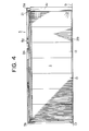
- the receiver members 20 are each formed of a grooved steel piece and are attached fast in a horizontal state with the support bolts 18 and are adapted to receive the lower reinforcing frames 13c2 of the wall panels 13 in a mutually fitted state in the upper part thereof (Fig. l7). Desired adjustment of the wall panels 13 in their height is accomplished by causing the receiver members 20 to be vertically moved with the rotation of the nuts 19. The upper ends of the wall panels 13 are supported in place with long retainer members 21 of a U-shaped cross section as illustrated in Fig. 4 and Fig. 18.
- a wall 31 containing an entrance door 30 to the preparatory room 2 has the same construction as the partition wall 3.
- the other walls of the preparatory room 2 have substantially the same construction as the external walls opposed to the partition wall of the airtight main room 1.
- the air inside the airtight main room 1 is sucked into the casing 8 of the second air-conditioner unit A2 via the air inlet 8al as indicated by the arrow in Fig. 11, cleaned with the HEPA filter 8j, and blown out horizontally into the room interior via the air outlet 8bl.
Abstract
Description
- This invention relates to a clean room which has no use for a machine compartment or an inlet or outlet duct.
- In the conventional clean room, a machine cubicle is installed as closely juxtaposed to an airtight main room, an air-conditioner is disposed inside the machine cubicle and, where the air circulation inside the airtight main room is of a vertical flow type, a ceiling provided with filters of high performance and a grated floor are interconnected with air inlet and outlet ducts, so that the air inside the airtight main room is circulated by means of the air-conditioner and cleaned by passage through the filters. The aforementioned air-conditioner may be any of the various types such as, for example, the type using an air blower exclusively, the type using both an air blower and a heat exchanger, and the type using a humidifier in addition to the two devices mentioned above.
- The conventional clean room described above suffers from complexity of construction because it necessitates installation of facilities and devices attendant on the air-conditioner and entails numerous jobs and various sorts of labor in the distribution of pipes and ducts. Moreover, this construction consumes much time. The total space for the clean room is required to allow a space for occupation by the machine cubicle and, therefore, is liable to be larger than is otherwise sufficient.
- The clean rooms now used in various industries, in terms of required cleanliness of interior air, range widely from a high level to a low level. The clean rooms used in highly technological industries engaging in assemblage of semiconductors and cultivation of microorganisms and bacteria are required to meet as high cleanliness as
Class 1, whereas those used in the industries devoted to cleaning of dust-free garments and packaging of foodstuffs are only required to meet cleanliness of the level of Class 10,000 and are not expected to provide such high cleanliness as normally prevalent in the highly technological industries. The clean rooms used in special industries and expected to provide high cleanliness are primarily aimed at enhancing the quality of products and, therefore, are required to tolerate the aforementioned drawbacks inherent in the conventional clean room construction. For the clean rooms used in ordinary industries which are satisfied with low degrees of cleanliness, the conventional construction is not suitable. In recent years, the desirability of developing a clean room which is constructed inexpensively and quickly in a small space and is readily disassembled has come to find growing recognition. - An object of this invention is to provide a clean room so constructed as to obviate the necessity for inlet and outlet ducts and a machine cubicle and, therefore, enjoy a saving on space. Another object of this invention is to provide a clean room such that it will be easily and quickly constructed and readily disassembled. Yet another object of this invention is to provide a clean room such that it will be freely enlarged (expanded) or reduced as occasion demand.
- This invention concerns a clean room designed to keep clean the interior air of an airtight main room by circulating the air through a circulation path and an air-conditioner and filters disposed in the circulation path, which clean room is characterized by having at least one air-conditioner unit built in the shell of the room behind part of the internal wall thereof, the air-conditioner unit being provided with an external casing of a small thickness, the external casing being provided in the lower part of the room interior-side thereof with an air inlet and in the upper part thereof with an air outlet fitted with a high-performance filter, the casing being further provided therein with an air blower, and the air blower being so adapted as to deliver forced air flow to the air outlet.
- This invention further concerns a clean room which is characterized by comprising a plurality of gate-shaped frames disposed parallelly in a prescribed direction as regularly spaced on a floor surface, an air-conditioner unit built in at least one of spaces intervening between the vertical members of the adjacent frames and forming part of the internal wall of the room, a control unit adapted to control the air-conditioner unit and built in one of the spaces intervening between the vertical members other than the space occupied by the air-conditioner unit, wall panels for covering the spaces intervening between the vertical members of the adjacent frames other than the space occupied by the air-conditioner unit and the spaces falling within the vertical members of the frames, wall panels for covering the outer lateral parts of the frames positioned outside, a ceiling panel covering the upper open end of an airtight main room defined by the wall panels, and means for tightly sealing the interior of the airtight main room, the air-conditioner unit being provided with an external casing of small thickness, the casing being provided in the lower part of the room interior side thereof with an air inlet and in the upper part thereof with an air outlet fitted with a high-performance filter, the casing being provided therein with an air blower, and the air blower being so adapted as to deliver a forced flow of air toward the air outlet, and the control unit being provided in a thin external casing thereof with mechanical items for control.
- The characteristic features of the present invention will be more fully understood from the further disclosure of this invention to be made in the following detailed description of preferred embodiments, with reference to the accompanying drawings.
-
- Fig. 1 is a partially omitted perspective view,
- Fig. 2 is a lateral cross section,
- Fig. 3 is a cross section taken through Fig. 1 along the line III-III,
- Fig. 4 is a cross section taken through Fig. 2 along the line IV-IV,
- Fig. 5 is an assembly drawing and disassembly drawing of a gate-shaped frame,
- Fig. 6 is an enlarged front view of the upper part of the gate-shaped frame,
- Fig. 7 is an enlarged plan view of part of the horizontal part of the gate-shaped frame,
- Fig. 8 is a partially cutaway front view of a first air-conditioner unit,
- Fig. 9 is a cross section taken through Fig. 8 along the line IX-IX,
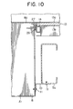
- Fig. 10 is a cross section illustrating as enlarged the state of interconnection between the first air-conditioner unit and the frame,
- Fig. 11 is a partially cutaway front view of a second air-conditioner unit,
- Fig. 12 is a longitudinal cross section illustrating as enlarged a control unit in a state erected upright,
- Fig. 13 is a cross'section taken through Fig: 12 along the line XIII-XIII,
- Fig. 14 is a lateral cross section of a joint part of a wall panel,
- Fig. 15 is a partially cutaway front view illustrating the lower part of the joint part of the wall panel,
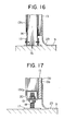
- Fig. 16 is a cros-s section taken through Fig. 15 along the line XVI-XVI,
- Fig. 17 is a cross section taken through Fig. 15 along the line XVII-XVII,
- Fig. 18 is an enlarged cross section taken through Fig. 2 along the line XVIII-XVIII,
- Fig. 19 is an enlarged cross section taken through Fig. 2 along the line XIX-XIX,
- Fig. 20 is a perspective view of a partition wall in a partially disassembled state,
- Fig. 21 is an enlarged cross section taken through Fig. 20 along the line XXI-XXI,
- Fig. 22 is an enlarged cross section taken through Fig. 20 along the line XXII-XXII,
- Fig. 23 is a lateral cross section illustrating as enlarged the state in which the corner portion of an airtight main room is set in place,
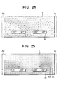
- Fig. 24 is an explanatory diagram illustrating distribution of air flow inside the airtight main room,
- Fig. 25 is an explanatory diagram illustrating distribution of dust inside the airtight main room,
- Fig. 26 is a diagram showing the numerical values of cleanliness within the airtight main room measured at three levels where the air circulation is effected by operation of one air-conditioner unit,
- Fig. 27 is a diagram showing the numerical values of cleanliness within the airtight main room measured at three levels where the air circulation is effected by operation of two air-conditioner units,
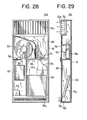
- Fig. 28 is a partially cutaway front view of another version of the first air-conditioner unit,
- Fig. 29 is a longitudinal cross section of the unit illustrated in Fig. 28, and
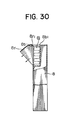
- Fig. 30 is a cross section illustrating another version of the air outlet.
- As illustrated in Figs. 1 through 4, the clean room comprises an airtight
main room 1 and apreparatory room 2 formed as adjoining the outside. of the airtight main room. Thepreparatory room 2 has anair shower room 2a at the center thereof as interposed between ananterior room 2b falling on the righthand side and aposterior room 2c on the lefthand side respectively with respect to Fig. 1. Via a door 4 formed in apartition wall 3, therooms - In the airtight
main room 1, three gate-shape frames 5 are parallelly arranged as spaced at intervals of 1000 mm in the recessing direction (vertical direction in Fig. 2) of the room. These frames form main structural members of the airtight main room. - Each of the gate-
shaped frames 5, as illustrated in Figs. 5 through 7, is obtained by joining rectangularvertical frames horizontal part 5c, i.e. the horizontal member of the gate. The gate-shaped frame 5 has a span (distance between the opposedvertical frames plates angles bolts 5f. The other edges of the external horizontal frames 5c2, 5c3 are fastened withbolts 5h ontoangles vertical frames plates bolts 5h to the connecting plates. Thehorizontal parts 5c of theframes 5 are joined one to another with a continuous support member 6 (Figs. 18, 19) disposed beneath thehorizontal parts 5c and formed of channel members. The horizontal parts and thecontinuous support member 6 are mutually bound with clips (not shown). Thecontinuous support member 6 has the lower side thereof keep in position abar 7 having an M-shaped cross section (Fig. 1). Further as illustrated in Figs. 1 through 4, in the space partitioned by thevertical frames vertical frames 5a which fall on the same side as the first air-conditioner unit Al. The control unit B is juxtaposed across thevertical frame 5a to the first air-conditioner unit Al and is opposed to the second air-conditioner unit A2 across the space of the airtight main room. - The first air-conditioner unit Al, as illustrated in Figs. 8 and 9, is provided with an
external casing 8 measuring about 2730 mm in height, 995 mm in width, and 250 mm in thickness. Thiscasing 8 is lined with glass wool. Thecasing 8 is covered on the front side thereof (the lefthand side in Fig. 9) with a lowerfront panel 8a and an upperfront panel 8b. The front panels are fastened in place withbolts 8c. An air inlet 8al is provided in the lower part of the lowerfront panel 8a and an air outlet 8bl is provided in the upperfront panel 8b. Inside thecasing 8, acoarse dust filter 8d is set in place as juxtaposed closely to the rear part of the air inlet 8al. Acooling coil 8e is attached fast to the rear part of this filter, anelectric heater 8f is disposed above the coil, and ahumidifier 8g is disposed diagonally above the heater. Further, anair blower 8h is disposed above theelectric heater 8f and guidevanes 8i are disposed as closely juxtaposed to a discharge tube 8h1 of the air blower. The air flow discharged from theair blower 8h is rectified by these guide vanes and led to the air outlet Bbl. Theair blower 8h comprises a blower casing of a small thickness, blades of a large area, and a motor of a low-speed rotation so as to abate the noise emitted during its operation. A HEPA (high efficiency penetration air)filter 8j is fastened to the rear side of the air outlet 8bl. Removal of the lowerfront panel 8a provides ready access to thefilter 8d for its replacement or to theair blower 8h for its repair and removal of the upperfront panel 8b permits access to theHEPA filter 8j for its replacement. The state of attachment of thecasing 8 will be described. Thecasing 8 is secured on the bottom side thereof to a floor surface 9 (Fig. 4) with an anchor member (not shown) and on the lateral sides thereof to thevertical frames 5a of theframe 5 with fixingplates 10 andbolts 11 as illustrated in Fig. 10. - The second air-conditioner unit A2 is substantially identical in principal features with the first air-conditioner unit Al as illustrated in Fig. 11, except for the fact that it is not provided with the
heat exchangers humidifier 8g possessed by the first air-conditioner unit Al. The symbols used for denoting the component parts of the second air-conditioner A2 are equal to those used for denoting the identical component parts of the first air-conditioner Al. The manner in which the second air-conditioner unit is fixed in place is similar to that of the first air-conditioner unit already described. - The control unit B, as illustrated in Figs. 1 and 2 and Figs. 12 and 13, is provided with a
casing 12 which is substantially identical in size with thecasing 8 for the air-conditioner units Al and A2. By virtue of the control devices incorporated in thecasing 12, the control unit fills the part of performing necessary electrical control on theair blower 8h and theheat exchangers air shower room 2a. Similarly to the air-conditioner units Al and A2, the control unit B is set fast in place by having the lateral sides of thecasing 12 thereof fastened to thevertical frames 5a of theframe 5 with fixingplates 10 andbolts 11 as illustrated in Fig. 13. Thecasing 12 is provided on the front side thereof with aplate 12 a set in plate in a projected manner and on the rear side thereof with arear lid 12b set in place in an openable state. Removal of therear lid 12b provides ready access to the mechanical devices held inside for inspection. - The internal walls of the airtight
main room 1 are formed ofwall panels 13 and the front sides of the air-conditioner units Al and A2 as illustrated in Figs. 1 through 4. - The construction of the internal walls on the lefthand and righthand sides of the airtight
main room 1 as illustrated in Fig. 1 will be described. All the intervals between the vertical frames of theframes 5 except for those incorporating the air-conditioner units Al and A2 are covered withwall panels 13. Each of thewall panels 13, as illustrated in Fig. 10 and Figs. 13 through 17, is composed of adecorative steel panel 13a and aplaster board 13b bonded to the entire rear side of this steel panel. Thewall panel 13 is reinforced with a reinforcingframe 13c which is formed of channel steel pieces laid around the boundary and in two horizontal levels in the center respectively of the rear side of theboard 13b.Posts 14 are raised upright from thefloor surface 9 in front of the vertical frames of each of theframes 5. Theposts 14 are each formed of an angular pipe provided at the lower end thereof with a retainer metal piece 15 (Figs. 15 and 16). The posts are immobilized on the floor surface by having themetal pieces 15 fastened to thefloor surface 9 with bolts l6. Between the adjacent posts are incorporated thewall panels 13. Lateral reinforcing frames 13cl fastened to the opposite sides of theposts 14 and to the opposite sides of thewall panels 13 serve to nip the posts fast in place and ensure stable lateral retention of the wall panels. The lower ends of thewall panels 13 are supported in plate, as illustrated in Figs. 14, 15, and 17, on combination bases andreceiver members 20 which are fastened withnuts 19 to supportbolts 18 raised upright onseat plates 17 disposed on thefloor surface 9. Thewall panels 13 each correspond to twosuch support bolts 18. Thereceiver members 20 are each formed of a grooved steel piece and are attached fast in a horizontal state with thesupport bolts 18 and are adapted to receive the lower reinforcing frames 13c2 of thewall panels 13 in a mutually fitted state in the upper part thereof (Fig. l7). Desired adjustment of thewall panels 13 in their height is accomplished by causing thereceiver members 20 to be vertically moved with the rotation of the nuts 19. The upper ends of thewall panels 13 are supported in place withlong retainer members 21 of a U-shaped cross section as illustrated in Fig. 4 and Fig. 18. - In the wall panels which cover the external sides of the airtight
main room 1 as illustrated in Fig. 2 and Fig. 19, the wall panels forming the internal walls as illustrated in Fig. 3 and on the righthand side of Fig. 19 are supported in place by a method substantially identical with the method adopted in supporting the wall panels on the same side as the air-conditioner unit Al. Thewall panels 13 on the lefthand side andwall panels 22 of thepreparatory room 2 jointly form apartition wall 3 for separating the airtightmain room 1 and thepreparatory room 2 from each other. The construction of thewall panels 22 is substantially identical with that of thewall panels 13, as illustrated in Figs. 19 through 22. Thewall panels frames posts 14 fixed in position as raised upright from thefloor surface 9. The manner in which theposts 14 are fastened to thefloor surface 9 is substantially identical with the manner for fastening the posts as already described (Fig. 16). The lower ends of thepanels receiver members 20 secured to thebolts 18 as illustrated in Fig. 22. Denoted by 22c2 are lower reinforcing frames. By manipulation of the nuts 19, desired adjustment of thereceiver members 20 in level can be accomplished. The upper ends of thepanels members 23 substantially identical in construction with the retaining members 21 (Fig. 18). - A
ceiling panel 24 in the airtightmain room 1 is made of glass wool sheets. As illustrated in Fig. 1 and Figs. 18 and 19, retainer bars 25 serving to support in plate theceiling panel 24 are supported by thebars 7 of the M-shaped cross section suspended from the long supportingmembers 6. - The method for tightly closing the airtight
main room 1 is as follows. The gaps between the first air-conditioner unit Al and thewall panels 13 are sealed, as illustrated in Fig. 10, by filling the gaps between the lateral sides of thecasing 8 and theposts 14 withelastic sealing members 27 laid in front of backup members. The gaps between the second air-conditioner unit A2 and thewall panels 13 are sealed in exactly the same manner as described above. The gaps along the joint lines between the adjoiningwall panels 13 are sealed, as illustrated in Fig. 13 and 14 and Fig. 21, by disposingelastic sealing members 27 andbackup members 26 in these gaps. Further, the corner portion of the airtightmain room 1 such as the gap occurring in the portion where thewall panel 13A containing a window (Fig. 1) and thewall panel 13 intersect each other is sealed, as illustrated in Fig. 23, by disposing abackup member 26 and anelastic sealing member 27 between the lateral part of the wall panel and the front side of the lateral edge of the wall panel. By 28 is denoted a cover panel. The other portions are sealed in exactly the same manner as described above. - Then, the gap between the
floor surface 9 and the lower end of the internal wall is sealed, as illustrated in Figs. 3 and 4, Fig. 12, and Figs. 14 through 17, by superposing a sealingsheet 29 of vinyl chloride on the entire upper surface of thefloor surface 9 and bonding the boundary of thesheet 29 to the lower side of the internal wall. In this case, the boundary of thesheet 29 concurrently serves as a baseboard. The boundary of theceiling panel 24 is likewise sealed with anelastic sealing member 27 as illustrated in Figs. 18 and 19. - A
wall 31 containing anentrance door 30 to thepreparatory room 2 has the same construction as thepartition wall 3. The other walls of thepreparatory room 2 have substantially the same construction as the external walls opposed to the partition wall of the airtightmain room 1. - Now, the method for assembling the clean room of this invention will be described below.
- First, three
frames 5 are set in place as regularly spaced on thefloor surface 9 and thehorizontal parts 5c of these frames are interconnected withcontinuous support members 6. Then, theposts 14 are set upright as regularly spaced along thevertical frames frames 5 as illustrated in Fig. 2 and theother posts 14 are similarly set upright as regularly spaced between the opposedvertical frames floor surface 9 with thebolts 16. Thereafter, the first air-conditioner unit Al and the control unit B are built in between the prescribed vertical frames on the onevertical frame 5a side. On the othervertical frame 5b side, the second air-conditioner unit A2 is built in the space intervening the vertical frames and opposed to the control unit B. In this case, the air-conditioner unit Al and the control unit B are not allowed to adjoin each other directly but must be disposed on both sides of onevertical frame 5a. - The
support bolts 18 and thereceiver members 20 are set in place on thefloor surface 9 between theposts 14. After the posts have been set fast, thewall panels 13 are joined as inserted between the posts. The lower ends of the panels are mounted on the receiver members, the reinforcing frames 13cl on the lateral parts are applied to the opposite sides of the posts, and the upper ends of the panels are supported by theretainer members ceiling panel 24 is set up in a suspended manner and the sealingsheet 29 is superposed on the entire surface of thefloor surface 9. The boundary of the sheet is bonded to the lower part of the internal wall. The interior of the airtight main room is tightly sealed by using thebackup members 26 and theelastic sealing members 27. The assembly of thepreparatory room 2 is carried out simultaneously with that of the airtightmain room 1. - The clean room assembled as described above may be disassembled when necessary by reversing the procedure described above.
- Now, the operation of the clean room of the present invention will be described below.
- As the control unit B is set operating to actuate the
air blower 8h, theheat exchangers humidifier 8g of the first air-conditioner unit Al and theair blower 8h of the second air-conditioner unit A2, the air inside the airtight main-room 1 is introduced into thecasing 8 of the first air-conditioner unit Al via the air inlet 8al, advanced as indicated by the arrow in Fig. 1 through thefilter 8d, thecooling coil 8e, and theelectric filter 8f, drawn into theair blower 8h and driven thereout in a forced flow of air, led upwardly by theguide vanes 8i, passed through theHEPA filter 8j and, now in the form of clean air, blown out horizontally into the room interior through the air outlet 8bl. The air, during its travel through the first air-conditioner unit is cooled by thecooling coil 8e or warmed by theelectric heater 8f. - At the same time, the air inside the airtight
main room 1 is sucked into thecasing 8 of the second air-conditioner unit A2 via the air inlet 8al as indicated by the arrow in Fig. 11, cleaned with theHEPA filter 8j, and blown out horizontally into the room interior via the air outlet 8bl. - The air blown out of the second air-conditioner unit A2 flows inside the airtight
main room 1 as indicated by the air flow distribution shown in Fig. 24. The dust density distribution inside the airtightmain room 1 is shown in Fig. 25. By 32 is denoted a desk placed inside themain room 1 and by the mark X is denoted a source of dust. It is noted from the diagram that the air flow stagnates on the air-conditioner Al side of the room interior. In Fig. 25, eachcircle 33 denotes a-dust particle in such a way that its radius increases with the increasing size of dust particle. It is noted from the diagram that large dust particles are suspended near the dust source. - The cleanliness inside the airtight
main room 1 was measured at various points on the floor at three different levels of 1500 mm, 1000 mm, and 500 mm. The results are shown in Fig. 26 and Fig. 27. The data of Fig. 26 were obtained when the air circulation inside the main room was effected by operating one air-conditioner unit. The data of Fig. 27 were obtained when the air circulation was effected by operating two air-conditioner units. As shown in the two diagrams, the cleanliness was measured at 35 points inside the airtight main room. These points of measurement are shown by circles "o", and identified with serial numbers 1 - 35, with found degrees of cleanliness indicated for the respective odd-numbered points. The mark X denotes the source of dust. First, Fig. 26 will be described. In this diagram, the degrees of cleanliness indicated at the points of measurement represent the results of measurement obtained when the air circulation inside the main room was effected by operating the air-conditioner unit Al alone. Fig. 26 (i) represents the data of the measurement performed at the level of 1500 mm above the floor. From the data, it is noted that the cleanliness was Class 760 at thepoint 1 of measurement and Class 1100 at thepoint 25 of measurement. The average cleanliness of the main room was Class 1190. Fig. 26 (ii) represents the data of the measurement performed at the level of 1000 mm above the floor. The average cleanliness of the main room was Class 960. Fig. 26 (iii) represents the data of the measurement performed at the level of 500 mm above the floor. The average cleanliness was Class 770. AtPoint 25 of measurement, for example, the cleanliness was Class 860, the highest degree, at the level of 500 mm above the floor, Class 1070, the medium degree, at the level of 1000 mm, and Class 1100, the lowest degree, at the level of 1500 mm. - Now, Fig. 27 will be described. This diagram represents the data obtained when the air circulation in the main room was effected by operating the two air-conditioner units Al and A2. Fig. 27 (i) represents the data of the measurement performed at the level of 1500 mm above the floor. The average cleanliness was Class 970. Figs. 27 (ii) and (iii) represent the data of the measurement performed at the respective levels of 1000 mm and 500 mm above the floor. The average cleanliness was Class 1120 and Class 850.
- Comparison of the data of cleanliness obtained at the level of 1500 mm above the floor under operation of two air-conditioner units and those obtained at the same level under operation of one air-conditioner unit reveals that at
Point 25 of measurement, for example, the cleanliness was Class 770 in the former case and Class 1100 in the latter case. This fact indicates that the cleanliness improves as the number of air-conditioner units increases and that still higher cleanliness is obtained by incorporating another air-conditioner unit A3 of the kind of the air-conditioner unit A2 in the space intervening between the vertical frames and opposed to the air-conditioner unit Al as indicated by the chain line in Fig. 2. - The number of air-conditioner units to be incorporated in the clean room is suitably selected, depending on the span (distance between the
vertical frame 5a and thevertical frame 5b) of the airtight main room, the degree of cleanliness desired, and the extent of dust generated. Where two or more air-conditioner units are required, the air-conditioner units Al and A2 may be suitably combined and thehumidifier 8g may be incorporated as occasion demands. Where no heat exchanger is required, incorporation of the air-conditioner unit A2 alone suffices. Although use of just one air-conditioner unit suffices for the primary purpose of the airtight main room, the cleanliness provided by the main room can be enhanced by using two such air-conditioner units. Then, use of two air-conditioner units as opposed to each other proves advantageous where the span of the airtight main room has a long span or where the clean room is required to provide cleanliness of high degree. - A desire to expand the airtight
main room 1 is accomplished by extending theroom 1 upwardly in the bearing thereof illustrated in Fig. 2. When this expansion is to be effected in the clean room illustrated in Fig. 2, for example, it is accomplished simply by having a fourth frame disposed at a distance of 1000 mm from the third frame (the framed situated in the uppermost part of the diagram of Fig. 2) as reckoned from theframe 5 on thepreparatory room 2 side. When this expansion requires incorporation of additional air-conditioner unit or units, such unit or units may be installed in both or either of the spaces intervening between the third and fourth frames. - When the sealing
sheet 29 is used as means of tightly closing the gap between thefloor surface 9 and the internal wall of the airtight main room, desired airtight closure is attained with high reliability by a simple and speedy work. - Another typical version of the air-conditioner unit Al will be described with reference to Figs. 28 and 29. An air-conditioner unit A4 is provided with functions substantially equal to the functions of the air-conditioner unit Al. It is provided in the central part of the front panel of the
casing 8 thereof (the lefthand sided illustrated in Fig. 29) with a single-swing door 8k. The air inlet 8al is provided on the rear sided thereof with acoarse dust filter 8d and is adapted to be opened forward about a hinge (not shown) fitted at the lower edge thereof. By thefilter 8j of the air outlet 8bl, the outgoing air flow is cleaned. On one side (lefthand side in Fig. 28) in the lower part of the interior of thecasing 8, thehumidifier 8g is disposed. On the other side is disposed thecooling coil 8e. Theelectric heater 8f is disposed above the humidifier. Thehumidifier 8g and theelectric heater 8f are partitioned off thecooling coil 8e with apartition wall 8m as. illustrated in Fig. 28. An opening 8n above the electric heater is opened or closed with aslide plate 8p. Theair blower 8h is set in place above the electric heater. Themechanical items 8e through 8h are controlled by anoperation panel 8q disposed inside thecasing 8. Desired access to these mechanical items can be obtained by opening thedoor 8k. These mechanical items may be severally removed for the purpose of replacement. Thehumidifier 8g, theelectric heater 8f, and theair blower 8h can be withdrawn forward from the casing and thecooling coil 8e can be withdrawn upwardly from its housing. In the present air-conditioner unit, the overall service life of the unit can be elongated because the mechanical items of varying service life can be replaced selectively from time to time. Thus, the unit can be given necessary maintenance easily. Since theoperation panel 8q takes the place of the control unit B, the clean room has no use for the unit B. - In the
casing 8 illustrated in Fig. 30, ahood 8r is detatchably attached to the front of the air outlet so that the direction in which the air flow is discharged from the air outlet 8bl may be freely selected. Thehood 8r is provided along the rear edge thereof with a hanging piece 8rl and the air outlet 8bl is provided on the upper front side thereof with ahook 8s, so that thehood 8r may be supported on the air outlet by having the hanging piece caught fast on the hook. Alternatively, the hood may be supported on the air outlet by allowing the hood to be tilted about a hinge provided at the lower part of the air outlet 8bl.
Claims (5)
Priority Applications (1)
| Application Number | Priority Date | Filing Date | Title |
|---|---|---|---|
| AT85113453T ATE43706T1 (en) | 1984-10-23 | 1985-10-23 | CLEANROOM. |
Applications Claiming Priority (4)
| Application Number | Priority Date | Filing Date | Title |
|---|---|---|---|
| JP221320/84 | 1984-10-23 | ||
| JP59221320A JPS61101732A (en) | 1984-10-23 | 1984-10-23 | Clean room |
| JP35286/85 | 1985-02-26 | ||
| JP60035286A JPS61195221A (en) | 1985-02-26 | 1985-02-26 | Clean room |
Publications (3)
| Publication Number | Publication Date |
|---|---|
| EP0180139A2 true EP0180139A2 (en) | 1986-05-07 |
| EP0180139A3 EP0180139A3 (en) | 1987-04-22 |
| EP0180139B1 EP0180139B1 (en) | 1989-05-31 |
Family
ID=26374246
Family Applications (1)
| Application Number | Title | Priority Date | Filing Date |
|---|---|---|---|
| EP85113453A Expired EP0180139B1 (en) | 1984-10-23 | 1985-10-23 | Clean room |
Country Status (8)
| Country | Link |
|---|---|
| US (1) | US4694736A (en) |
| EP (1) | EP0180139B1 (en) |
| KR (1) | KR920007808B1 (en) |
| CN (1) | CN1010426B (en) |
| DE (1) | DE3525920A1 (en) |
| ES (1) | ES8609673A1 (en) |
| GB (1) | GB2165936B (en) |
| PT (1) | PT81355B (en) |
Cited By (3)
| Publication number | Priority date | Publication date | Assignee | Title |
|---|---|---|---|---|
| EP0218210A1 (en) * | 1985-10-03 | 1987-04-15 | Daw, Incorporated | Cleanroom structure |
| GB2188413A (en) * | 1986-02-13 | 1987-09-30 | Philip Arthur Richard Stukley | Central heating system |
| GB2198762A (en) * | 1986-10-29 | 1988-06-22 | Aoki Corp | Mobile controlled clean room laboratory unit |
Families Citing this family (41)
| Publication number | Priority date | Publication date | Assignee | Title |
|---|---|---|---|---|
| US4860915A (en) * | 1987-07-20 | 1989-08-29 | Standard Havens, Inc. | Baghouse with integral wall stiffeners |
| JPH0759993B2 (en) * | 1988-06-30 | 1995-06-28 | 株式会社小松製作所 | Radiant local air conditioner |
| EP0457747B1 (en) * | 1990-05-11 | 1994-11-30 | Albert Dupont | Wine recorking apparatus and method |
| JPH0813680B2 (en) * | 1990-06-15 | 1996-02-14 | 株式会社大氣社 | Aircraft work equipment |
| JP2561749B2 (en) * | 1990-10-11 | 1996-12-11 | 株式会社朝日工業社 | Clean room air circulation method |
| JP3309416B2 (en) * | 1992-02-13 | 2002-07-29 | 松下電器産業株式会社 | Connected clean space device |
| DE4238595C2 (en) * | 1992-11-16 | 1996-04-11 | Kessler & Luch Gmbh | Modular ventilation unit with integrated fan and connected filter frame, especially for clean room purposes |
| US5472466A (en) * | 1994-05-04 | 1995-12-05 | Oler; James H. | Smoker's module |
| JP3654612B2 (en) * | 1996-09-24 | 2005-06-02 | 株式会社ルネサステクノロジ | Clean room |
| DE19805096C2 (en) * | 1998-02-09 | 1999-12-16 | Primed Medizintechnik Gmbh | Capillary drainage hose system |
| ITGE20010013A1 (en) * | 2001-02-09 | 2002-08-09 | Impresa Marinoni S R L | STRUCTURES SUITABLE FOR THE INSTALLATION OF WET ROOMS AND RELATED ASSEMBLY PROCEDURE. |
| DK1543727T3 (en) * | 2003-12-19 | 2007-06-25 | Kraft Foods R & D Inc | Wax coated cheese |
| US7350370B2 (en) * | 2004-06-15 | 2008-04-01 | Lg Electronics Inc. | Air conditioner |
| US20060213157A1 (en) * | 2005-03-28 | 2006-09-28 | Kalous D S | Wall-embeddable air processing apparatus |
| DE202005008334U1 (en) * | 2005-05-27 | 2006-10-05 | Opitz + Flierl Hospitaltechnik Ag | cleanroom |
| US10651063B2 (en) | 2005-06-18 | 2020-05-12 | Frederick A. Flitsch | Methods of prototyping and manufacturing with cleanspace fabricators |
| US10627809B2 (en) | 2005-06-18 | 2020-04-21 | Frederick A. Flitsch | Multilevel fabricators |
| US7513822B2 (en) | 2005-06-18 | 2009-04-07 | Flitsch Frederick A | Method and apparatus for a cleanspace fabricator |
| US9159592B2 (en) | 2005-06-18 | 2015-10-13 | Futrfab, Inc. | Method and apparatus for an automated tool handling system for a multilevel cleanspace fabricator |
| US9339900B2 (en) | 2005-08-18 | 2016-05-17 | Futrfab, Inc. | Apparatus to support a cleanspace fabricator |
| US9059227B2 (en) | 2005-06-18 | 2015-06-16 | Futrfab, Inc. | Methods and apparatus for vertically orienting substrate processing tools in a clean space |
| US9457442B2 (en) * | 2005-06-18 | 2016-10-04 | Futrfab, Inc. | Method and apparatus to support process tool modules in a cleanspace fabricator |
| US11024527B2 (en) | 2005-06-18 | 2021-06-01 | Frederick A. Flitsch | Methods and apparatus for novel fabricators with Cleanspace |
| US7467024B2 (en) * | 2005-08-26 | 2008-12-16 | Flitsch Frederick A | Method and apparatus for an elevator system for a multilevel cleanspace fabricator |
| CN105304529B (en) | 2005-09-18 | 2019-03-15 | 弗雷德里克·A·弗里奇 | Method and apparatus for the perpendicular positioning substrate processing equipment in clean room |
| FR2899918B1 (en) * | 2006-04-14 | 2010-10-01 | Vladimir Grcevic | MOBILE LABORATORY FOR THE ANALYSIS OF PATHOGENIC AGENTS |
| JP2009002634A (en) * | 2007-06-25 | 2009-01-08 | Unitec Inc | Unit type clean room |
| MX2011006850A (en) | 2008-12-23 | 2011-08-15 | Xoma Technology Ltd | Flexible manufacturing system. |
| US9795957B2 (en) * | 2009-08-16 | 2017-10-24 | G-Con Manufacturing, Inc. | Modular, self-contained, mobile clean room |
| ES2665972T3 (en) | 2009-08-16 | 2018-04-30 | G-Con Manufacturing Inc. | Modular autonomous mobile white room |
| US8627672B2 (en) * | 2009-08-27 | 2014-01-14 | Sanyo Electric Co., Ltd. | Wall-hung air conditioner and installing device for air conditioner |
| DE102010007720A1 (en) * | 2010-02-10 | 2011-08-11 | Vivotecnia Research S.L. | Laboratory module for performing experiment for animal husbandry, has inner wall with controllable aperture, so that definable amount of air flows from inner space into intermediate space per time unit |
| EP2714240A4 (en) * | 2011-05-27 | 2015-06-03 | Clarcor Air Filtration Products Inc | Non v-bank filter for animal confinement facility |
| US9687766B2 (en) | 2011-05-27 | 2017-06-27 | Clarcor Air Filtration Products, Inc. | Collapsible and/or assembled filter housing and filter used therewith |
| US9034068B2 (en) | 2012-06-05 | 2015-05-19 | Clarcor Air Filtration Products, Inc. | Box filter with orientation device |
| DK3058147T3 (en) * | 2013-10-14 | 2023-01-30 | G Con Mfg Inc | CONNECTION DEVICE FOR CONNECTING MODULAR MOBILE SPACES AND SIMILAR CONNECTION METHOD |
| CA2970498C (en) | 2014-12-11 | 2023-03-28 | Edward R. Di Girolamo | Multiplace hyperbaric chamber systems and methods |
| CN106193380A (en) * | 2015-04-30 | 2016-12-07 | 昆山协多利洁净系统股份有限公司 | Used in electronic industry cleaning partition wall system |
| CN105696725B (en) * | 2016-01-29 | 2018-04-10 | 东北大学 | A kind of heat radiating type building enclosure suitable for high-density heating object |
| IL290639B (en) | 2019-08-15 | 2022-08-01 | G Con Mfg Inc | Removable panel roof for modular, self-contained, mobile clean room |
| US11492795B2 (en) | 2020-08-31 | 2022-11-08 | G-Con Manufacturing, Inc. | Ballroom-style cleanroom assembled from modular buildings |
Citations (7)
| Publication number | Priority date | Publication date | Assignee | Title |
|---|---|---|---|---|
| US3158457A (en) * | 1962-05-14 | 1964-11-24 | Willis J Whitfield | Ultra-clean room |
| GB1013383A (en) * | 1962-02-27 | 1965-12-15 | John Bass Ltd | Improvements in clean rooms |
| FR2299901A1 (en) * | 1975-02-07 | 1976-09-03 | Hoechst Ag | AIR PURIFICATION DEVICE |
| WO1981000443A1 (en) * | 1979-08-02 | 1981-02-19 | Luwa Ag | Casing,particularly for air conditioning and ventilation machines as well as textile machines |
| EP0067577A1 (en) * | 1981-05-26 | 1982-12-22 | Graham Steed Roberts | Modular room construction |
| US4409889A (en) * | 1981-11-02 | 1983-10-18 | Burleson Maurice L | Modular clean room |
| EP0107298A2 (en) * | 1982-09-06 | 1984-05-02 | Shyoji Hirayama | Air cleaning apparatus |
Family Cites Families (5)
| Publication number | Priority date | Publication date | Assignee | Title |
|---|---|---|---|---|
| US1937829A (en) * | 1932-06-02 | 1933-12-05 | Air Way Electric Appl Corp | Air conditioner |
| GB669866A (en) * | 1949-07-27 | 1952-04-09 | Leonard John Fowler | Improvements in or relating to air-conditioning, ventilating and heating apparatus |
| DE6947148U (en) * | 1969-12-04 | 1970-03-12 | Trox Gmbh Geb | DEVICE FOR SUPPLYING FILTERED AIR INTO CLEANROOMS OR CLEANROOM WORK CABINS |
| CH539823A (en) * | 1971-06-17 | 1973-07-31 | Pielkenrood Vinitex Bv | Device for the supply of a germ-free air stream over an operating table |
| IE801418L (en) * | 1980-07-08 | 1982-01-08 | Leo Prendergast Snr | Nuclear shelter |
-
1985
- 1985-07-01 GB GB8516585A patent/GB2165936B/en not_active Expired
- 1985-07-06 KR KR1019850004848A patent/KR920007808B1/en not_active IP Right Cessation
- 1985-07-19 DE DE19853525920 patent/DE3525920A1/en active Granted
- 1985-10-22 US US06/790,308 patent/US4694736A/en not_active Expired - Fee Related
- 1985-10-22 ES ES548115A patent/ES8609673A1/en not_active Expired
- 1985-10-22 CN CN85107712A patent/CN1010426B/en not_active Expired
- 1985-10-23 PT PT81355A patent/PT81355B/en not_active IP Right Cessation
- 1985-10-23 EP EP85113453A patent/EP0180139B1/en not_active Expired
Patent Citations (7)
| Publication number | Priority date | Publication date | Assignee | Title |
|---|---|---|---|---|
| GB1013383A (en) * | 1962-02-27 | 1965-12-15 | John Bass Ltd | Improvements in clean rooms |
| US3158457A (en) * | 1962-05-14 | 1964-11-24 | Willis J Whitfield | Ultra-clean room |
| FR2299901A1 (en) * | 1975-02-07 | 1976-09-03 | Hoechst Ag | AIR PURIFICATION DEVICE |
| WO1981000443A1 (en) * | 1979-08-02 | 1981-02-19 | Luwa Ag | Casing,particularly for air conditioning and ventilation machines as well as textile machines |
| EP0067577A1 (en) * | 1981-05-26 | 1982-12-22 | Graham Steed Roberts | Modular room construction |
| US4409889A (en) * | 1981-11-02 | 1983-10-18 | Burleson Maurice L | Modular clean room |
| EP0107298A2 (en) * | 1982-09-06 | 1984-05-02 | Shyoji Hirayama | Air cleaning apparatus |
Cited By (5)
| Publication number | Priority date | Publication date | Assignee | Title |
|---|---|---|---|---|
| EP0218210A1 (en) * | 1985-10-03 | 1987-04-15 | Daw, Incorporated | Cleanroom structure |
| GB2188413A (en) * | 1986-02-13 | 1987-09-30 | Philip Arthur Richard Stukley | Central heating system |
| GB2198762A (en) * | 1986-10-29 | 1988-06-22 | Aoki Corp | Mobile controlled clean room laboratory unit |
| US4850268A (en) * | 1986-10-29 | 1989-07-25 | Aoki Corporation | Multi-purpose, mobile laboratory room |
| GB2198762B (en) * | 1986-10-29 | 1991-05-01 | Aoki Corp | Mobile laboratory room |
Also Published As
| Publication number | Publication date |
|---|---|
| CN1010426B (en) | 1990-11-14 |
| GB2165936A (en) | 1986-04-23 |
| KR860003477A (en) | 1986-05-26 |
| DE3525920A1 (en) | 1986-04-24 |
| GB2165936B (en) | 1989-07-12 |
| EP0180139B1 (en) | 1989-05-31 |
| US4694736A (en) | 1987-09-22 |
| PT81355B (en) | 1987-09-18 |
| CN85107712A (en) | 1986-05-10 |
| PT81355A (en) | 1985-11-01 |
| GB8516585D0 (en) | 1985-08-07 |
| EP0180139A3 (en) | 1987-04-22 |
| ES548115A0 (en) | 1986-09-01 |
| ES8609673A1 (en) | 1986-09-01 |
| KR920007808B1 (en) | 1992-09-17 |
| DE3525920C2 (en) | 1992-03-19 |
Similar Documents
| Publication | Publication Date | Title |
|---|---|---|
| EP0180139B1 (en) | Clean room | |
| US4699640A (en) | Clean room having partially different degree of cleanliness | |
| US5297990A (en) | Filter-ventilator-arrangement | |
| US5284027A (en) | Air conditioning systems | |
| CA2049929A1 (en) | Air conditioning unit for laboratory animals | |
| JPS6314257B2 (en) | ||
| US6637232B1 (en) | Unit ventilator | |
| US4586486A (en) | Multilevel air distribution panel for air ventilation hood | |
| US3031944A (en) | Ceiling air diffuser | |
| EP1941212B1 (en) | Method of operating a plurality of clean room | |
| EP0692084B1 (en) | Apparatus for cooling room air | |
| KR100759135B1 (en) | Modular clean room filter system | |
| JPH02111411A (en) | Hanging cleaning unit | |
| JPH0332914Y2 (en) | ||
| JP2857584B2 (en) | Heat exchanger | |
| JPH08261531A (en) | Clean room system | |
| JPH06221611A (en) | Air-conditioner embedded in ceiling | |
| JPS61195221A (en) | Clean room | |
| US1954456A (en) | Air conditioning apparatus | |
| JP2001153414A (en) | Circulation type clean room | |
| JPS6036838A (en) | Cleaned room device | |
| JP2549212B2 (en) | Air conditioner | |
| JPS62182541A (en) | Clean room | |
| JP2537247B2 (en) | Clean room | |
| JPS62155455A (en) | Clean room |
Legal Events
| Date | Code | Title | Description |
|---|---|---|---|
| PUAI | Public reference made under article 153(3) epc to a published international application that has entered the european phase |
Free format text: ORIGINAL CODE: 0009012 |
|
| AK | Designated contracting states |
Kind code of ref document: A2 Designated state(s): AT BE CH FR IT LI LU NL SE |
|
| PUAL | Search report despatched |
Free format text: ORIGINAL CODE: 0009013 |
|
| AK | Designated contracting states |
Kind code of ref document: A3 Designated state(s): AT BE CH FR IT LI LU NL SE |
|
| 17P | Request for examination filed |
Effective date: 19870727 |
|
| 17Q | First examination report despatched |
Effective date: 19880122 |
|
| GRAA | (expected) grant |
Free format text: ORIGINAL CODE: 0009210 |
|
| AK | Designated contracting states |
Kind code of ref document: B1 Designated state(s): AT BE CH FR IT LI LU NL SE |
|
| REF | Corresponds to: |
Ref document number: 43706 Country of ref document: AT Date of ref document: 19890615 Kind code of ref document: T |
|
| ITF | It: translation for a ep patent filed |
Owner name: BARZANO' E ZANARDO MILANO S.P.A. |
|
| ET | Fr: translation filed | ||
| PLBE | No opposition filed within time limit |
Free format text: ORIGINAL CODE: 0009261 |
|
| STAA | Information on the status of an ep patent application or granted ep patent |
Free format text: STATUS: NO OPPOSITION FILED WITHIN TIME LIMIT |
|
| 26N | No opposition filed | ||
| ITTA | It: last paid annual fee | ||
| PGFP | Annual fee paid to national office [announced via postgrant information from national office to epo] |
Ref country code: SE Payment date: 19920910 Year of fee payment: 8 |
|
| PGFP | Annual fee paid to national office [announced via postgrant information from national office to epo] |
Ref country code: FR Payment date: 19920914 Year of fee payment: 8 |
|
| PGFP | Annual fee paid to national office [announced via postgrant information from national office to epo] |
Ref country code: LU Payment date: 19920924 Year of fee payment: 8 |
|
| PGFP | Annual fee paid to national office [announced via postgrant information from national office to epo] |
Ref country code: CH Payment date: 19921009 Year of fee payment: 8 |
|
| PGFP | Annual fee paid to national office [announced via postgrant information from national office to epo] |
Ref country code: BE Payment date: 19921014 Year of fee payment: 8 |
|
| PGFP | Annual fee paid to national office [announced via postgrant information from national office to epo] |
Ref country code: AT Payment date: 19921028 Year of fee payment: 8 |
|
| PGFP | Annual fee paid to national office [announced via postgrant information from national office to epo] |
Ref country code: NL Payment date: 19921031 Year of fee payment: 8 |
|
| EPTA | Lu: last paid annual fee | ||
| PG25 | Lapsed in a contracting state [announced via postgrant information from national office to epo] |
Ref country code: LU Free format text: LAPSE BECAUSE OF NON-PAYMENT OF DUE FEES Effective date: 19931023 Ref country code: AT Effective date: 19931023 |
|
| PG25 | Lapsed in a contracting state [announced via postgrant information from national office to epo] |
Ref country code: SE Effective date: 19931024 |
|
| PG25 | Lapsed in a contracting state [announced via postgrant information from national office to epo] |
Ref country code: LI Effective date: 19931031 Ref country code: CH Effective date: 19931031 Ref country code: BE Effective date: 19931031 |
|
| BERE | Be: lapsed |
Owner name: SHIMIZU KENSETSU K.K. Effective date: 19931031 |
|
| PG25 | Lapsed in a contracting state [announced via postgrant information from national office to epo] |
Ref country code: NL Effective date: 19940501 |
|
| NLV4 | Nl: lapsed or anulled due to non-payment of the annual fee | ||
| PG25 | Lapsed in a contracting state [announced via postgrant information from national office to epo] |
Ref country code: FR Effective date: 19940630 |
|
| REG | Reference to a national code |
Ref country code: CH Ref legal event code: PL |
|
| REG | Reference to a national code |
Ref country code: FR Ref legal event code: ST |
|
| EUG | Se: european patent has lapsed |
Ref document number: 85113453.6 Effective date: 19940510 |