EP0180528A2 - Method for the medical analysis of a liquid sample by means of at least one liquid reagent, and apparatus for carrying out the method - Google Patents
Method for the medical analysis of a liquid sample by means of at least one liquid reagent, and apparatus for carrying out the method Download PDFInfo
- Publication number
- EP0180528A2 EP0180528A2 EP85420183A EP85420183A EP0180528A2 EP 0180528 A2 EP0180528 A2 EP 0180528A2 EP 85420183 A EP85420183 A EP 85420183A EP 85420183 A EP85420183 A EP 85420183A EP 0180528 A2 EP0180528 A2 EP 0180528A2
- Authority
- EP
- European Patent Office
- Prior art keywords
- weir
- sample
- capillary
- liquid
- reagent
- Prior art date
- Legal status (The legal status is an assumption and is not a legal conclusion. Google has not performed a legal analysis and makes no representation as to the accuracy of the status listed.)
- Withdrawn
Links
Images


Classifications
-
- G—PHYSICS
- G01—MEASURING; TESTING
- G01N—INVESTIGATING OR ANALYSING MATERIALS BY DETERMINING THEIR CHEMICAL OR PHYSICAL PROPERTIES
- G01N21/00—Investigating or analysing materials by the use of optical means, i.e. using sub-millimetre waves, infrared, visible or ultraviolet light
- G01N21/01—Arrangements or apparatus for facilitating the optical investigation
- G01N21/03—Cuvette constructions
- G01N21/07—Centrifugal type cuvettes
-
- Y—GENERAL TAGGING OF NEW TECHNOLOGICAL DEVELOPMENTS; GENERAL TAGGING OF CROSS-SECTIONAL TECHNOLOGIES SPANNING OVER SEVERAL SECTIONS OF THE IPC; TECHNICAL SUBJECTS COVERED BY FORMER USPC CROSS-REFERENCE ART COLLECTIONS [XRACs] AND DIGESTS
- Y10—TECHNICAL SUBJECTS COVERED BY FORMER USPC
- Y10T—TECHNICAL SUBJECTS COVERED BY FORMER US CLASSIFICATION
- Y10T436/00—Chemistry: analytical and immunological testing
- Y10T436/11—Automated chemical analysis
- Y10T436/111666—Utilizing a centrifuge or compartmented rotor
-
- Y—GENERAL TAGGING OF NEW TECHNOLOGICAL DEVELOPMENTS; GENERAL TAGGING OF CROSS-SECTIONAL TECHNOLOGIES SPANNING OVER SEVERAL SECTIONS OF THE IPC; TECHNICAL SUBJECTS COVERED BY FORMER USPC CROSS-REFERENCE ART COLLECTIONS [XRACs] AND DIGESTS
- Y10—TECHNICAL SUBJECTS COVERED BY FORMER USPC
- Y10T—TECHNICAL SUBJECTS COVERED BY FORMER US CLASSIFICATION
- Y10T436/00—Chemistry: analytical and immunological testing
- Y10T436/25—Chemistry: analytical and immunological testing including sample preparation
- Y10T436/25625—Dilution
-
- Y—GENERAL TAGGING OF NEW TECHNOLOGICAL DEVELOPMENTS; GENERAL TAGGING OF CROSS-SECTIONAL TECHNOLOGIES SPANNING OVER SEVERAL SECTIONS OF THE IPC; TECHNICAL SUBJECTS COVERED BY FORMER USPC CROSS-REFERENCE ART COLLECTIONS [XRACs] AND DIGESTS
- Y10—TECHNICAL SUBJECTS COVERED BY FORMER USPC
- Y10T—TECHNICAL SUBJECTS COVERED BY FORMER US CLASSIFICATION
- Y10T436/00—Chemistry: analytical and immunological testing
- Y10T436/25—Chemistry: analytical and immunological testing including sample preparation
- Y10T436/2575—Volumetric liquid transfer
Definitions
- the present invention relates to a method for carrying out medical analysis of a liquid sample of at least one liquid reagent.
- the present invention aims to implement a method for analyzing a very low dose of liquid sample, of the order of a few microliters. This is particularly interesting in the case of medical analyzes because it becomes possible, for example, to avoid patients having to undergo blood tests by means of syringes, and to simply use a few drops of blood collected after a finger.
- Means are provided for positioning said box on the plate of a centrifuge according to several determined positions deduced from one another by a rotation of the box on itself, relative to the plate at a given angle.
- said determined positions of the case are deduced from each other by rotations of the order of 90 and 180 °, corresponding substantially to the angles which said capillary conduits make between them ending in said spillway.
- the capillary conduits have diameters of the order of two tenths of a millimeter.
- the case is closed by a plastic cover provided with a sample storage receptacle communicating directly with said sample storage chamber and located above it.
- the cover also has a chimney located above said overflow and intended to receive a plug capable of closing all the orifices opening into said overflow.
- This chimney as well as said receptacle constitute with the cover a unitary plastic part, the assembly having come from molding.
- the capillary conduits connecting said calibrated cell and a reagent storage chamber with the weir are parallel to each other.
- the capillary conduits connecting two other reagent storage chambers with the weir are diametrically opposite with respect to the weir and form an angle substantially equal to 90 ° with the two aforementioned capillary conduits.
- Said overflow advantageously comprises internal ribs forming deflectors making it possible to prevent a reagent expelled from a storage chamber from entering another storage chamber.
- Figures 1 and 2 show that the upper part of the cover (2) carries a storage receptacle (3) for a liquid sample communicating directly with a sample storage chamber (4) inside the housing.
- the storage chamber (4) is connected by a capillary conduit (5) to a calibrated cell (6) communicating by a capillary conduit (7) with an overflow chamber (8), and by a capillary conduit (10) with a weir (20).
- the latter provided with deflecting ribs (21) and (22), communicates with an analysis tank (11) at the level of the upper part of a common wall (23).
- a fourth reagent storage chamber formed by two cells (60) and (62), communicating with each other through an orifice (63); only the cell (60) communicates with the weir (20) via a capillary conduit (61).
- the latter has a direction substantially at an angle of 45 ° with the conduits (10,31,41,51).
- the cover (2) carries above the weir (20) a chimney (12) capable of receiving a plug (13).
- the stopper (13) has the function of closing all the orifices opening into the outlet (20) (capillary conduits 31, 41, 51, 61 in particular).
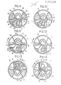
- Figures 9 to 20 show a top view of the device of Figures 1 to 8 during the implementation of the method according to the invention.
- FIG. 9 illustrates the initial phase, when the chambers (30, 40, 50, 60 and 62) of the housing (1) have received reagents (35, 45, 55, 65 respectively).
- the center of rotation of the plate is located so that the end of the cell (6) corresponding to the capillary duct (7) is further away from it than the end corresponding to the capillary duct (10).
- the direction of the centrifugal force is substantially that of the capillary conduits (10) and (31).
- the stopper (13) is removed and a drop of sample (15) of a few microliters is introduced into the receptacle (3).
- the sample (15) ends up in the storage chamber (4) (see Figure 10).
- a first centrifugation is then carried out, an intermediate phase (FIG. 11) and the final phase (FIG. 12) having been illustrated.
- the reagents remain stored in their respective chambers but the sample (15) passes through the calibrated cell (6) and the capillary conduit (7).
- the calibrated cell (6) is filled with sample (15), the excess ends up in the overflow chamber (8).
- a second centrifugation is carried out (see Figures 14 and 15); the sample (15) passes through the capillary conduit (10) in the tank (20) then in the analysis tank (11). Simultaneously the reagent (35) passes through the capillary conduit (31) in the weir (20) and the tank (11). Orientation to centrifugal force capillary conduits (41,51,61) is such that the other reagents remain trapped in their respective storage chambers.
- Figure 15 shows the housing at rest after the second centrifugation: the cell (6) and the reservoir (30) are empty.
- the first centrifugation Figures 11,12
- a final 90 ° rotation of the housing (1) is made around its axis and placing the capillary duct (51) in such a way that a fifth centrifugation allows the reagent (55) to be chased towards the tank (11) where the mixture (100) is then obtained.
- reaction which has appeared in this mixture can be observed by any suitable means.
Abstract
Procédé destiné à réaliser l'analyse médicale d'un échantillon liquide à l'aide d'au moins un réactif liquide et dispositif pour la mise en oeuvre du procédé. Procédé pour réaliser l'analyse médicale d'un échantillon liquide utilisant un boîtier (1) unitaire en matière plastique, compartimenté de manière à comporter une chambre de stockage (4) pour l'échantillon, une cellule calibrée (6), et des chambres de stockage (40,50,60) pour des réactifs liquides. Diverses centrifugations permettent de faire passer successivement l'échantillon et les réactifs dans une cuve d'analyse (11).Method for carrying out the medical analysis of a liquid sample using at least one liquid reagent and device for carrying out the method. Method for carrying out medical analysis of a liquid sample using a unitary plastic casing (1), compartmentalized so as to include a storage chamber (4) for the sample, a calibrated cell (6), and chambers storage (40.50.60) for liquid reagents. Various centrifugations allow the sample and the reagents to pass successively through an analysis tank (11).
Description
La présente invention concerne un procédé destiné à réaliser l'analyse médicale d'un échantillon liquide d'au moins un réactif liquide.The present invention relates to a method for carrying out medical analysis of a liquid sample of at least one liquid reagent.
La présente invention a pour but de mettre en oeuvre un procédé d'analyse d'une très faible dose d'échantillon liquide, de l'ordre de quelques microlitres. Ceci est particulièrement intéressant dans le cas d'analyses médicales car il devient possible, par exemple, d'éviter aux patients de subir des prises de sang au moyen de seringues, et d'utiliser simplement quelques gouttes de sang recueillies au bout d'un doigt.The present invention aims to implement a method for analyzing a very low dose of liquid sample, of the order of a few microliters. This is particularly interesting in the case of medical analyzes because it becomes possible, for example, to avoid patients having to undergo blood tests by means of syringes, and to simply use a few drops of blood collected after a finger.
Elle a également pour but de mettre au point un procédé permettant de réaliser toutes les analyses médicales demandées jusqu'à présent (de l'ordre de trois cents), au moyen de quatre réactifs différents au maximum.It also aims to develop a process for carrying out all the medical analyzes requested so far (of the order of three hundred), using a maximum of four different reagents.
Elle a pour but enfin de mettre en oeuvre un procédé bon marché et simple pour l'opérateur, qui se sert de boitiers stockés contenant des réactifs liquides ; ceci est rendu possible par le fait que les réactifs liquides possèdent un temps de conservation tout à fait satisfaisant (de l'ordre de dix huit mois à deux ans).Finally, it aims to implement a cheap and simple process for the operator, which uses stored boxes containing liquid reagents; this is made possible by the fact that the liquid reagents have a quite satisfactory storage time (of the order of eighteen months to two years).
La présente invention a pour objet un procédé destiné à réaliser l'analyse médicale d'un échantillon liquide à l'aide d'au moins un réactif liquide, remarquable notamment par le fait qu'il utilise un boitier compartimenté de façon à présenter :
- - une chambre de stockage pour ledit échantillon liquide reliée par un conduit capillaire à une extrémité d'une cellule calibrée dont l'autre extrémité est reliée par un conduit capillaire à une chambre de trop-plein ;
- - plusieurs chambres de stockage pour des réactifs liquides disposées autour d'un déversoir, ledit déversoir étant relié respectivement par des conduits capillaires d'orientations diverses à ladite cellule calibrée et auxdites chambres de stockage de réactif, et communiquant par ailleurs avec une cuve d'analyse.
- - a storage chamber for said liquid sample connected by a capillary conduit to one end of a calibrated cell, the other end of which is connected by a capillary conduit to an overflow chamber;
- - several storage chambers for liquid reagents arranged around a weir, said weir being connected respectively by capillary conduits of various orientations to said calibrated cell and to said reagent storage chambers, and also communicating with an analysis tank.
Ledit boitier est fermé par un couvercle muni d'une part d'un réceptacle de stockage d'échantillon communiquant directement avec ladite chambre de stockage d'échantillon et situé au-dessus d'elle, et d'autre part d'un bouchon amovible entrant dans ledit déversoir pour obturer les extrémités desdits conduits capillaires qui y aboutissent.Said case is closed by a cover provided on the one hand with a sample storage receptacle communicating directly with said sample storage chamber and situated above it, and on the other hand with a removable plug entering said weir to close off the ends of said capillary conduits which terminate there.
Des moyens sont prévus pour positionner ledit boitier sur le plateau d'une centrifugeuse selon plusieurs positions déterminées se déduisant l'une de l'autre par une rotation du boitier sur lui-même, par rapport au plateau selon un angle donné.Means are provided for positioning said box on the plate of a centrifuge according to several determined positions deduced from one another by a rotation of the box on itself, relative to the plate at a given angle.
Selon ce procédé, on a disposé initialement des réactifs liquides respectivement dans lesdites chambres de stockage de réactif, on introduit ledit échantillon dans ledit réceptacle de stockage d'échantillon, ce dernier s'écoulant alors par gravité dans ladite chambre de stockage d'échantillon ; on enlève ledit bouchon, on met en place ledit boitier sur ledit plateau de la centrifugeuse en vue de réaliser successivement plusieurs centrifugations, la position angulaire du boitier étant à chaque fois choisie, parmi lesdites positions déterminées, en fonction de l'orientation du conduit capillaire concerné par rapport à la direction de la force centrifuge, de manière à.faire passer successivement ledit échantillon de ladite chambre de stockage d'échantillon dans ladite cellule calibrée, puis de cette manière dans ledit déversoir et dans ladite cuve d'analyse, et ensuite chaque réactif de sa chambre de stockage dans ledit déversoir et ladite cuve d'analyse.According to this method, liquid reagents are initially placed respectively in said reagent storage chambers, said sample is introduced into said sample storage receptacle, the latter then flowing by gravity into said sample storage chamber; removing said cap, placing said housing on said plate of the centrifuge in order to carry out successively several centrifugations, the angular position of the housing being each time chosen from said determined positions, depending on the orientation of the capillary duct concerned with respect to the direction of the centrifugal force, so as to pass said sample successively from said sample storage chamber in said calibrated cell, then in this way in said weir and in said analysis tank, and then each reagent from its storage chamber in said weir and said analysis tank.
Selon un mode de réalisation particulièrement avantageux, lesdites positions déterminées du boitier se déduisent les unes des autres par des rotations de l'ordre de 90 et de 180°, correspondant sensiblement aux angles que font entre eux lesdits conduits capillaires aboutissant dans ledit réversoir.According to an embodiment particularly before tagous, said determined positions of the case are deduced from each other by rotations of the order of 90 and 180 °, corresponding substantially to the angles which said capillary conduits make between them ending in said spillway.
La présente invention a également pour objet un dispositif pour la mise en oeuvre du procédé précité. Il s'agit d'un boitier cylindrique plat en matière plastique dont le diamètre est de l'ordre de trois centimètres et qui est compartimenté intérieurement de façon à présenter :
- - une chambre de stockage pour ledit échantillon liquide reliée par un conduit capillaire à une extrémité d'une cellule calibrée dont l'autre extrémité est reliée par un conduit capillaire à une chambre de trop-plein ;
- - plusieurs chambres de stockage pour des réactifs liquides disposées autour d'un déversoir, ledit déversoir étant relié respectivement par des conduits capillaires d'orientations diverses à ladite cellule calibrée et auxdites chambres de stockage de réactif, et communiquant par ailleurs avec une cuve d'analyse.
- - a storage chamber for said liquid sample connected by a capillary conduit to one end of a calibrated cell, the other end of which is connected by a capillary conduit to an overflow chamber;
- - Several storage chambers for liquid reagents arranged around a spillway, said spillway being connected respectively by capillary conduits of various orientations to said calibrated cell and to said reagent storage chambers, and also communicating with a tank of analysis.
Ledit boitier constitue une pièce unitaire venue de moulage. Les conduits capillaires ont des diamètres de l'ordre de deux dizièmes de millimètre.Said case constitutes a unitary piece coming from molding. The capillary conduits have diameters of the order of two tenths of a millimeter.
Le boitier est fermé par un couvercle en matière plastique muni d'un réceptacle de stockage d'échantillon communiquant directement avec ladite chambre de stockage d'échantillon et situé au-dessus d'elle. Le couvercle présente également une cheminée située au-dessus dudit déversoir et destinée à recevoir un bouchon susceptible d'obturer tous les orifices débouchant dans ledit dévervoir. Cette cheminée ainsi que ledit réceptacle constituent avec le couvercle une pièce unitaire en matière plastique, l'ensemble étant venu du moulage.The case is closed by a plastic cover provided with a sample storage receptacle communicating directly with said sample storage chamber and located above it. The cover also has a chimney located above said overflow and intended to receive a plug capable of closing all the orifices opening into said overflow. This chimney as well as said receptacle constitute with the cover a unitary plastic part, the assembly having come from molding.
Selon un mode de réalisation particulièrement avantageux, les conduits capillaires faisant communiquer ladite cellule calibrée et une chambre de stockage de réactif avec le déversoir sont parallèles entre eux. Les conduits capillaires faisant communiquer deux autres chambres de stockage de réactif avec le déversoir sont diamètralement opposés par rapport au déversoir et font un angle sensiblement égal à 90° avec les deux conduits capillaires précités.According to a particularly advantageous embodiment, the capillary conduits connecting said calibrated cell and a reagent storage chamber with the weir are parallel to each other. The capillary conduits connecting two other reagent storage chambers with the weir are diametrically opposite with respect to the weir and form an angle substantially equal to 90 ° with the two aforementioned capillary conduits.
Ledit déversoir comporte avantageusement des nervures internes formant déflecteurs permettant d'éviter qu'un réactif chassé d'une chambre de stockage ne pénètre dans une autre chambre de stockage.Said overflow advantageously comprises internal ribs forming deflectors making it possible to prevent a reagent expelled from a storage chamber from entering another storage chamber.
D'autres caractéristiques et avantages de l'invention apparaîtront au cours de la description d'un mode de réalisation d'un dispositif permettant la mise en oeuvre du procédé selon l'invention. Dans le dessin annexé :
- - la figure 1 est une vue de dessus du boitier sans son couvercle ;
- - les figures 2 à 8 sont respectivement des coupes selon les lignes II-II à VIII-VIII de la figure 1.;
- - les figures 9 à 20 montrent schématiquement les diverses positions du boitier contenant son échantillon et ses réactifs pendant les différentes phases du procédé selon l'invention.
- - Figure 1 is a top view of the housing without its cover;
- - Figures 2 to 8 are respectively sections along lines II-II to VIII-VIII of Figure 1 .;
- - Figures 9 to 20 schematically show the various positions of the container containing its sample and its reagents during the different phases of the process according to the invention.
On voit dans les figures 1 à 8 un boitier (1) en matière plastique de forme générale cylindrique et plate, fermé par un couvercle (2) en matière plastique. A titre d'exemple, le boitier a un diamètre de l'ordre de trois centimètres.We see in Figures 1 to 8 a housing (1) of plastic of generally cylindrical and flat shape, closed by a cover (2) of plastic. For example, the case has a diameter of the order of three centimeters.
Les figures 1 et 2 montrent que la partie supérieure du couvercle (2) porte un réceptacle de stockage (3) pour un échantillon liquide communicuant directement avec une chambre (4) de stockage d'échantillon intérieure au boitier.Figures 1 and 2 show that the upper part of the cover (2) carries a storage receptacle (3) for a liquid sample communicating directly with a sample storage chamber (4) inside the housing.
La chambre de stockage (4) est reliée par un conduit capillaire (5) à une cellule calibrée (6) communiquant par un conduit capillaire (7) avec une chambre de trop-plein (8), et par un conduit capillaire (10) avec un déversoir (20). Ce dernier, muni de nervures déflectrices (21) et (22), communique avec une cuve d'analyse (11) au niveau de la partie supérieure d'une paroi commune (23).The storage chamber (4) is connected by a capillary conduit (5) to a calibrated cell (6) communicating by a capillary conduit (7) with an overflow chamber (8), and by a capillary conduit (10) with a weir (20). The latter, provided with deflecting ribs (21) and (22), communicates with an analysis tank (11) at the level of the upper part of a common wall (23).
Le boitier comporte en outre une pluralité de chambres de stockage pour des réactifs liquides, telles que la chambre (30) qui communique avec le déversoir (20) par l'intermédiaire d'un conduit capillaire (31). On peut remarquer ici que les conduits capillaires (10) et (31) sont sensiblement parallèles entre eux. On a référencé (40) et (50) deux autres chambres de stockage de réactif communiquant avec le déversoir (20) respectivement par deux conduits capillaires (41) et (51), diamétralement opposés par rapport au déversoir, et orientés sensiblement à 90° par rapport aux conduits capillaires (10) et (31).The housing further includes a plurality of storage chambers for liquid reagents, such as the chamber (30) which communicates with the weir (20) via a capillary conduit (31). It can be noted here that the capillary conduits (10) and (31) are substantially parallel to one another. We have referenced (40) and (50) two other reagent storage chambers communicating with the weir (20) respectively by two capillary conduits (41) and (51), diametrically opposite with respect to the weir, and oriented substantially at 90 °. relative to the capillary conduits (10) and (31).
Enfin, il est prévu une quatrième chambre de stockage de réactif formée de deux alvéoles (60) et (62), communiquant entre eux par un orifice (63) ; seul l'alvéole (60) communique avec le déversoir (20) par un conduit capillaire (61). Ce dernier a une direction faisant sensiblement un angle de 45° avec les conduits (10,31,41,51).Finally, there is provided a fourth reagent storage chamber formed by two cells (60) and (62), communicating with each other through an orifice (63); only the cell (60) communicates with the weir (20) via a capillary conduit (61). The latter has a direction substantially at an angle of 45 ° with the conduits (10,31,41,51).
Le couvercle (2) porte au-dessus du déversoir (20) une cheminée (12) susceptible de recevoir un bouchon (13). Pendant toute la durée de conservation du boitier muni de ses réactifs, le bouchon (13) a pour fonction d'obturer tous les orifices débouchant dans le dévervoir (20) (conduits capillaires 31,41,51,61, notamment).The cover (2) carries above the weir (20) a chimney (12) capable of receiving a plug (13). During the entire shelf life of the container provided with its reagents, the stopper (13) has the function of closing all the orifices opening into the outlet (20) (
Les figures 9 à 20 montrent en vue de dessus le dispositif des figures 1 à 8 pendant la mise en oeuvre du procédé selon l'invention.Figures 9 to 20 show a top view of the device of Figures 1 to 8 during the implementation of the method according to the invention.
La figure 9 illustre la phase initiale, lorsque les chambres (30,40,50,60 et 62) du boitier (1) ont reçu respectivement des réactifs (35,45,55,65).FIG. 9 illustrates the initial phase, when the chambers (30, 40, 50, 60 and 62) of the housing (1) have received reagents (35, 45, 55, 65 respectively).
On dispose alors le boitier (1) sur le plateau d'une centrifugeuse. On imagine que l'on peut disposer simul- ténament une douzaine au moins de tels boitiers suivant un cercle sur ledit plateau.The casing (1) is then placed on the plate of a centrifuge. We imagine that we can simultaneously have at least a dozen such boxes in a circle on said plate.
Le centre de rotation du plateau est situé de manière que l'extrémité de la cellule (6) correspondant au conduit capillaire (7) en soit plus éloignée que l'extrémité correspondant au conduit capillaire (10). La direction de la force centrifuge est sensiblement celle des conduits capillaires (10) et (31).The center of rotation of the plate is located so that the end of the cell (6) corresponding to the capillary duct (7) is further away from it than the end corresponding to the capillary duct (10). The direction of the centrifugal force is substantially that of the capillary conduits (10) and (31).
A ce moment, le bouchon (13) est enlevé et une goutte d'échantillon (15) de quelques microlitres est introduit dans le réceptacle (3). L'échantillon (15) aboutit dans la chambre de stockage (4) (voir figure 10).At this time, the stopper (13) is removed and a drop of sample (15) of a few microliters is introduced into the receptacle (3). The sample (15) ends up in the storage chamber (4) (see Figure 10).
On réalise alors une première centrifugation dont on a illustré une phase intermédiaire (figure 11) et la phase finale (figure 12). Les réactifs restent stockés dans leurs chambres respectives mais l'échantillon (15) passe dans la cellule calibrée (6) et le conduit capillaire (7). Lorsque la cellule calibrée (6) est remplie d'échantillon (15), l'excédent aboutit dans la chambre de trop-plein (8).A first centrifugation is then carried out, an intermediate phase (FIG. 11) and the final phase (FIG. 12) having been illustrated. The reagents remain stored in their respective chambers but the sample (15) passes through the calibrated cell (6) and the capillary conduit (7). When the calibrated cell (6) is filled with sample (15), the excess ends up in the overflow chamber (8).
On réalise ensuite une rotation à 180° du boitier sur lui-même (voir figure 13) ; les conduits capillaires (10) et (31) sont donc encore parallèles à la direction de la force centrifuge.We then perform a 180 ° rotation of the housing on itself (see Figure 13); the capillary conduits (10) and (31) are therefore still parallel to the direction of the centrifugal force.
On opère une seconde centrifugation (voir figures 14 et 15) ; l'échantillon (15) passe par le conduit capillaire (10) dans le dévervoir (20) puis dans la cuve d'analyse (11). Simultanément le réactif (35) passe par le conduit capillaire (31) dans le déversoir (20) et la cuve (11). L'orientation vis-à-vis de la force centrifuge des conduits capillaires (41,51,61) est telle que les autres réactifs restent prisonniers dans leurs chambres de stockage respectives. La figure 15 montre le boîtier au repos après la seconde centrifugation : la cellule (6) et le réservoir (30) sont vides. On remarque également que la première centrifugation (figures 11,12) a eu pour effet de faire passer tout le réactif (65) dans l'alvéole (62) qui n'a pas de communication avec le déversoir et que cet état s'est maintenu au cours de la seconde centrifugation.A second centrifugation is carried out (see Figures 14 and 15); the sample (15) passes through the capillary conduit (10) in the tank (20) then in the analysis tank (11). Simultaneously the reagent (35) passes through the capillary conduit (31) in the weir (20) and the tank (11). Orientation to centrifugal force capillary conduits (41,51,61) is such that the other reagents remain trapped in their respective storage chambers. Figure 15 shows the housing at rest after the second centrifugation: the cell (6) and the reservoir (30) are empty. We also note that the first centrifugation (Figures 11,12) had the effect of passing all the reagent (65) into the cell (62) which has no communication with the weir and that this state has maintained during the second centrifugation.
Comme le montre la figure 16, on réalise une rotation de 90° du boitier (1) sur lui-même. Les conduits capillaires (51) et (41) se trouvent alors parallèles à la direction de la force centrifuge, mais par une troisième centrifugation seul le réactif (45) peut être chassé vers le déversoir (20) et la cuve d'analyse (11). Le réactif (45) est dévié par la nervure (22) vers la cuve (11) et ne risque pas de pénétrer dans la chambre (50). Le réactif (65) passe de l'alvéole (62) à l'alvéole (60) qui est en communication avec le déversoir (20).As shown in Figure 16, there is a 90 ° rotation of the housing (1) on itself. The capillary conduits (51) and (41) are then parallel to the direction of the centrifugal force, but by a third centrifugation only the reagent (45) can be removed to the weir (20) and the analysis tank (11 ). The reagent (45) is deflected by the rib (22) towards the tank (11) and does not risk entering the chamber (50). The reagent (65) passes from the cell (62) to the cell (60) which is in communication with the weir (20).
Comme cela apparaît dans la figure 17, on effectue une nouvelle rotation de 90° du boitier autour de son axe. La direction du capillaire (51) est telle que seul le réactif (65) peut être chassé vers le déversoir (20) par une quatrième centrifugation (voir figures 18 et 19).As it appears in figure 17, one carries out a new rotation of 90 ° of the case around its axis. The direction of the capillary (51) is such that only the reagent (65) can be removed to the weir (20) by a fourth centrifugation (see Figures 18 and 19).
Enfin, on réalise une dernière rotation de 90° du boitier (1) autour de son axe et plaçant le conduit capillaire (51) de façon telle qu'une cinquième centrifugation permette de chasser le réactif (55) vers la cuve (11) où l'on obtient alors le mélange (100).Finally, a final 90 ° rotation of the housing (1) is made around its axis and placing the capillary duct (51) in such a way that a fifth centrifugation allows the reagent (55) to be chased towards the tank (11) where the mixture (100) is then obtained.
La réaction apparue dans ce mélange peut être observée par tout moyen approprié.The reaction which has appeared in this mixture can be observed by any suitable means.
On a décrit un dispositif de mise en oeuvre utilisant quatre réactifs liquides, mais certaines réactions ne nécessitent qu'un, deux ou trois réactifs ; certaines des chambres de stockage de réactif peuvent rester vides. Selon une autre variante, on peut prévoir plusieurs types de boitiers contenant des nombres de chambres de stockage différents.An implementation device has been described using four liquid reagents, but certain reactions require only one, two or three reagents; some reagent storage chambers may remain empty. According to another variant, it is possible to provide several types of boxes containing different numbers of storage chambers.
On pourra, sans sortir du cadre de l'invention, remplacer tout moyen par un moyen équivalent.Without departing from the scope of the invention, any means can be replaced by equivalent means.
Claims (5)
caractérisé par le fait qu'il utilise un boitier (1) compartimenté intérieurement de façon à présenter :
characterized by the fact that it uses a box (1) compartmentalized internally so as to present:
Applications Claiming Priority (2)
| Application Number | Priority Date | Filing Date | Title |
|---|---|---|---|
| FR8416447A FR2572533B1 (en) | 1984-10-26 | 1984-10-26 | METHOD FOR CARRYING OUT THE MEDICAL ANALYSIS OF A LIQUID SAMPLE USING AT LEAST ONE LIQUID REAGENT AND DEVICE FOR CARRYING OUT THE METHOD |
| FR8416447 | 1984-10-26 |
Publications (2)
| Publication Number | Publication Date |
|---|---|
| EP0180528A2 true EP0180528A2 (en) | 1986-05-07 |
| EP0180528A3 EP0180528A3 (en) | 1987-05-27 |
Family
ID=9309044
Family Applications (1)
| Application Number | Title | Priority Date | Filing Date |
|---|---|---|---|
| EP85420183A Withdrawn EP0180528A3 (en) | 1984-10-26 | 1985-10-18 | Method for the medical analysis of a liquid sample by means of at least one liquid reagent, and apparatus for carrying out the method |
Country Status (7)
| Country | Link |
|---|---|
| US (1) | US4743558A (en) |
| EP (1) | EP0180528A3 (en) |
| JP (1) | JPS61108968A (en) |
| CN (1) | CN85107716A (en) |
| BR (1) | BR8505342A (en) |
| FR (1) | FR2572533B1 (en) |
| IL (1) | IL76824A0 (en) |
Cited By (2)
| Publication number | Priority date | Publication date | Assignee | Title |
|---|---|---|---|---|
| FR2600775A1 (en) * | 1986-06-26 | 1987-12-31 | Kis Photo Ind | BIOMEDICAL ANALYSIS DEVICE |
| FR2671629A1 (en) * | 1991-01-10 | 1992-07-17 | Kis Photo Ind | Device for analysis of a liquid sample |
Families Citing this family (36)
| Publication number | Priority date | Publication date | Assignee | Title |
|---|---|---|---|---|
| US4892708A (en) * | 1987-07-01 | 1990-01-09 | Miles Inc. | Fluid separation and processing device |
| US5173262A (en) * | 1987-07-17 | 1992-12-22 | Martin Marietta Energy Systems, Inc. | Rotor assembly and method for automatically processing liquids |
| US4835106A (en) * | 1987-07-17 | 1989-05-30 | Martin Marietta Energy Systems, Inc. | Rotor for processing liquids using movable capillary tubes |
| US5242803A (en) * | 1987-07-17 | 1993-09-07 | Martin Marietta Energy Systems, Inc. | Rotor assembly and assay method |
| US5160702A (en) * | 1989-01-17 | 1992-11-03 | Molecular Devices Corporation | Analyzer with improved rotor structure |
| US5326165A (en) * | 1991-06-26 | 1994-07-05 | Irvine Scientific Sales Co. | Mixing apparatus |
| US5304348A (en) * | 1992-02-11 | 1994-04-19 | Abaxis, Inc. | Reagent container for analytical rotor |
| US6235531B1 (en) | 1993-09-01 | 2001-05-22 | Abaxis, Inc. | Modified siphons for improved metering precision |
| US5591643A (en) * | 1993-09-01 | 1997-01-07 | Abaxis, Inc. | Simplified inlet channels |
| JPH10501340A (en) * | 1994-06-06 | 1998-02-03 | アバクシス,インコーポレイテッド | Improved siphon to improve measurement accuracy |
| EP1363739B1 (en) * | 2000-11-02 | 2011-12-21 | CaridianBCT, Inc. | Fluid separation devices, systems and methods |
| EP1410044A2 (en) * | 2000-11-08 | 2004-04-21 | Burstein Technologies, Inc. | Interactive system for analyzing biological samples and processing related information and the use thereof |
| AU2002241602A1 (en) * | 2000-11-16 | 2002-06-11 | Burstein Technologies, Inc. | Methods and apparatus for detecting and quantifying lymphocytes with optical biodiscs |
| AU2002219979A1 (en) * | 2000-12-01 | 2002-06-11 | Burstein Technologies, Inc. | Apparatus and methods for separating components of particulate suspension |
| US6760298B2 (en) * | 2000-12-08 | 2004-07-06 | Nagaoka & Co., Ltd. | Multiple data layer optical discs for detecting analytes |
| WO2002046761A2 (en) * | 2000-12-08 | 2002-06-13 | Burstein Technologies, Inc. | Methods for detecting analytes using optical discs and optical disc readers |
| WO2004010099A2 (en) * | 2001-05-16 | 2004-01-29 | Burstein Technologies, Inc. | Variable sampling for rendering pixelization of analysis results in optical bio-disc assembly |
| WO2003027723A2 (en) * | 2001-07-24 | 2003-04-03 | Burstein Technologies, Inc. | Method and apparatus for bonded fluidic circuit for optical bio-disc |
| US20040226348A1 (en) * | 2001-07-24 | 2004-11-18 | Phillip Bruce | Magnetic assisted detection of magnetic beads using optical disc drives |
| US20030129665A1 (en) * | 2001-08-30 | 2003-07-10 | Selvan Gowri Pyapali | Methods for qualitative and quantitative analysis of cells and related optical bio-disc systems |
| WO2003021222A2 (en) * | 2001-08-31 | 2003-03-13 | Burstein Technologies, Inc. | Capture layer assemblies for cellular assays including related optical analysis discs and methods |
| EP1423699A4 (en) * | 2001-09-07 | 2006-01-18 | Burstein Technologies Inc | Nuclear morphology based identification and quantitation of white blood cell types using optical bio-disc systems |
| CA2468041A1 (en) * | 2001-11-20 | 2003-05-30 | Burstein Technologies, Inc. | Optical bio-discs and microfluidic devices for analysis of cells |
| US20050176059A1 (en) * | 2002-01-31 | 2005-08-11 | Pal Andrew A. | Bio-safe dispenser and optical analysis disc assembly |
| US20040241381A1 (en) * | 2002-01-31 | 2004-12-02 | Chen Yihfar | Microfluidic structures with circumferential grooves for bonding adhesives and related optical analysis discs |
| US20050221048A1 (en) * | 2002-01-31 | 2005-10-06 | James Rodney Norton | Manufacturing processes for making optical analysis discs including successive patterning operations and optical discs thereby manufactured |
| WO2004095034A1 (en) * | 2003-04-23 | 2004-11-04 | Nagaoka & Co., Ltd. | Optical bio-discs including spiral fluidic circuits for performing assays |
| US7390464B2 (en) * | 2003-06-19 | 2008-06-24 | Burstein Technologies, Inc. | Fluidic circuits for sample preparation including bio-discs and methods relating thereto |
| WO2004113871A2 (en) * | 2003-06-19 | 2004-12-29 | Nagaoka & Co., Ltd. | Fluidic circuits for sample preparation including bio-discs and methods relating thereto |
| EP1644184A2 (en) * | 2003-06-27 | 2006-04-12 | Nagaoka & Co., Ltd. | Fluidic circuits, methods and apparatus for use of whole blood samples in colorimetric assays |
| US20070274863A1 (en) * | 2003-07-25 | 2007-11-29 | Horacio Kido | Fluidic circuits for sample preparation including bio-discs and methods relating thereto |
| DE212004000062U1 (en) * | 2003-11-14 | 2006-07-20 | Oakville Trading Hong Kong Ltd. | Sample collector with integrated sample analysis system |
| JP4614992B2 (en) * | 2007-07-27 | 2011-01-19 | パナソニック株式会社 | Analytical device, analytical apparatus and analytical method using the same |
| CA2859167C (en) | 2011-12-12 | 2021-03-16 | Step Ahead Innovations, Inc. | Submerged chemical indicator and holder |
| WO2014205230A1 (en) | 2013-06-19 | 2014-12-24 | Step Ahead Innovations Inc. | Aquatic environment water parameter testing systems and methods |
| CN108792258A (en) * | 2018-05-21 | 2018-11-13 | 南京申友生物技术有限公司 | A kind of genetic test kit |
Citations (4)
| Publication number | Priority date | Publication date | Assignee | Title |
|---|---|---|---|---|
| US3759666A (en) * | 1971-12-09 | 1973-09-18 | Union Carbide Corp | Analytical process |
| EP0062907A1 (en) * | 1981-04-14 | 1982-10-20 | Jean Guigan | Method and apparatus for delivering a predetermined amount of sample liquid to a cell |
| FR2524874A1 (en) * | 1982-04-07 | 1983-10-14 | Guigan Jean | Serological etc. analysis of liq. sample - by transfer between reagent cells via capillaries in multicell bar pivoted on centrifuge plate |
| EP0160282A2 (en) * | 1984-05-03 | 1985-11-06 | Abbott Laboratories | Processor card for centrifuge |
Family Cites Families (11)
| Publication number | Priority date | Publication date | Assignee | Title |
|---|---|---|---|---|
| US3211368A (en) * | 1962-11-05 | 1965-10-12 | Giovanni Raccuglia | Method and apparatus for treating liquid mixtures |
| FR2067639A5 (en) * | 1969-11-12 | 1971-08-20 | Guigan Jean | |
| SE384271B (en) * | 1971-01-07 | 1976-04-26 | J Guigan | LIQUID DISTRIBUTION DEVICE FOR SAME DISTRIBUTION OF CALIBRATED QUANTITIES OF A LIQUID TO SECONDARY CONTAINERS |
| US3814582A (en) * | 1972-03-02 | 1974-06-04 | Beckman Instruments Inc | Automated chemical analyser system |
| US3890101A (en) * | 1974-02-15 | 1975-06-17 | Us Energy | Collection ring for use in multiple-sample blood fractionation centrifugal rotors |
| US3951608A (en) * | 1975-01-22 | 1976-04-20 | Ernest Trod | Mixing cuvette and timing turntable for providing reaction mixtures |
| FR2409514A1 (en) * | 1977-11-17 | 1979-06-15 | Bretaudiere Jean Pierre | DEVELOPMENT OF CENTRIFUGATION ANALYSIS EQUIPMENT |
| FR2496268A1 (en) * | 1980-12-15 | 1982-06-18 | Guigan Jean | AUTONOMOUS SIMULTANEOUS ANALYSIS DEVICE AND METHOD FOR IMPLEMENTING SAME |
| FR2519763A1 (en) * | 1982-01-14 | 1983-07-18 | Guigan Jean | PACKAGING DEVICE FOR MULTIPLE ANALYSIS |
| US4632908A (en) * | 1984-05-03 | 1986-12-30 | Abbott Laboratories | Heating system for rotating members |
| FR2579756B1 (en) * | 1985-03-26 | 1987-05-07 | Guigan Jean | METHOD FOR PERFORMING BIOLOGICAL ANALYSIS USING IMMUNOLOGICAL REACTIONS AND DEVICE FOR CARRYING OUT SAID METHOD |
-
1984
- 1984-10-26 FR FR8416447A patent/FR2572533B1/en not_active Expired
-
1985
- 1985-10-18 EP EP85420183A patent/EP0180528A3/en not_active Withdrawn
- 1985-10-22 US US06/790,011 patent/US4743558A/en not_active Expired - Fee Related
- 1985-10-22 CN CN198585107716A patent/CN85107716A/en active Pending
- 1985-10-25 JP JP60240345A patent/JPS61108968A/en active Pending
- 1985-10-25 BR BR8505342A patent/BR8505342A/en unknown
- 1985-10-25 IL IL76824A patent/IL76824A0/en unknown
Patent Citations (4)
| Publication number | Priority date | Publication date | Assignee | Title |
|---|---|---|---|---|
| US3759666A (en) * | 1971-12-09 | 1973-09-18 | Union Carbide Corp | Analytical process |
| EP0062907A1 (en) * | 1981-04-14 | 1982-10-20 | Jean Guigan | Method and apparatus for delivering a predetermined amount of sample liquid to a cell |
| FR2524874A1 (en) * | 1982-04-07 | 1983-10-14 | Guigan Jean | Serological etc. analysis of liq. sample - by transfer between reagent cells via capillaries in multicell bar pivoted on centrifuge plate |
| EP0160282A2 (en) * | 1984-05-03 | 1985-11-06 | Abbott Laboratories | Processor card for centrifuge |
Cited By (4)
| Publication number | Priority date | Publication date | Assignee | Title |
|---|---|---|---|---|
| FR2600775A1 (en) * | 1986-06-26 | 1987-12-31 | Kis Photo Ind | BIOMEDICAL ANALYSIS DEVICE |
| EP0251946A1 (en) * | 1986-06-26 | 1988-01-07 | KIS PHOTO INDUSTRIE S.a.r.l. | Liquid sample analysing device |
| US4857274A (en) * | 1986-06-26 | 1989-08-15 | Kis Photo Industrie | Device for analyzing a liquid sample |
| FR2671629A1 (en) * | 1991-01-10 | 1992-07-17 | Kis Photo Ind | Device for analysis of a liquid sample |
Also Published As
| Publication number | Publication date |
|---|---|
| JPS61108968A (en) | 1986-05-27 |
| CN85107716A (en) | 1986-07-16 |
| BR8505342A (en) | 1986-08-05 |
| FR2572533A1 (en) | 1986-05-02 |
| FR2572533B1 (en) | 1986-12-26 |
| IL76824A0 (en) | 1986-02-28 |
| EP0180528A3 (en) | 1987-05-27 |
| US4743558A (en) | 1988-05-10 |
Similar Documents
| Publication | Publication Date | Title |
|---|---|---|
| EP0180528A2 (en) | Method for the medical analysis of a liquid sample by means of at least one liquid reagent, and apparatus for carrying out the method | |
| EP0183627A2 (en) | Method for the medical analysis of a liquid sample by means of at least one dry reagent, and apparatus for carrying out the method | |
| EP0251946B1 (en) | Liquid sample analysing device | |
| EP0197865A1 (en) | Method and apparatus for performing biological analyses using immunological reactions | |
| EP0352689B1 (en) | Device for biological analyses by enzymimmunassay detection of antibodies or antigens in a serum | |
| CA1272942A (en) | Process and device to dispence a predetermined amount of plasma from a blood specimen for analysis | |
| EP0352690B1 (en) | Mini laboratory for biological analyses by chemical reaction starting from a blood sample | |
| EP0062907B1 (en) | Method and apparatus for delivering a predetermined amount of sample liquid to a cell | |
| EP0469504B1 (en) | Device for centrifugally separating two phases of a heterogeneous liquid, in particular for use in the separation of blood plasma | |
| EP0658489B1 (en) | Device for the delivery of spherical products of the same dimensions, such as pills | |
| EP0197866B1 (en) | Method and apparatus for performing medical analyses using dry reagents | |
| EP0066828B1 (en) | Apparatus and method for successively making contact between a liquid sample and a plurality of reagents | |
| FR2464100A1 (en) | CENTRIFUGAL SEPARATOR WITH OVERFLOW DEVICE | |
| CA1276602C (en) | Device for delivering a predetermined dose of a liquid | |
| EP0657207A1 (en) | Device for making, protected from the air, a paste for cosmetic use | |
| FR2665647A1 (en) | BOTTLE FOR CHEMICAL REAGENTS. | |
| CA2072402C (en) | Apparatus for sampling a predetermined constant quantity of a liquid | |
| FR2589240A1 (en) | Single-parameter analysis bar | |
| EP0082778B1 (en) | Can and container assembly comprising a can and a flask | |
| WO2009150359A1 (en) | Device for colouring microscope slides | |
| FR2584855A1 (en) | CONTAINER FOR MEDIUM OR LOW ACTIVITY RADIOACTIVE WASTE | |
| FR2488701A1 (en) | TANK OF PHOTOGRAPHIC DEVELOPMENT | |
| FR2777807A1 (en) | Turbine for circulating mass of material of specified viscosity | |
| FR2763566A1 (en) | Viscous liquid container, holding and pouring viscous liquids e.g. shower gel, liquid detergents, oils, syrups, adhesives | |
| FR2671629A1 (en) | Device for analysis of a liquid sample |
Legal Events
| Date | Code | Title | Description |
|---|---|---|---|
| PUAI | Public reference made under article 153(3) epc to a published international application that has entered the european phase |
Free format text: ORIGINAL CODE: 0009012 |
|
| AK | Designated contracting states |
Kind code of ref document: A2 Designated state(s): AT BE CH DE GB IT LI LU NL SE |
|
| PUAL | Search report despatched |
Free format text: ORIGINAL CODE: 0009013 |
|
| AK | Designated contracting states |
Kind code of ref document: A3 Designated state(s): AT BE CH DE GB IT LI LU NL SE |
|
| 17P | Request for examination filed |
Effective date: 19871120 |
|
| 17Q | First examination report despatched |
Effective date: 19890711 |
|
| STAA | Information on the status of an ep patent application or granted ep patent |
Free format text: STATUS: THE APPLICATION IS DEEMED TO BE WITHDRAWN |
|
| 18D | Application deemed to be withdrawn |
Effective date: 19900228 |