EP0181723A1 - Low mass heat and pressure fuser - Google Patents
Low mass heat and pressure fuser Download PDFInfo
- Publication number
- EP0181723A1 EP0181723A1 EP85307764A EP85307764A EP0181723A1 EP 0181723 A1 EP0181723 A1 EP 0181723A1 EP 85307764 A EP85307764 A EP 85307764A EP 85307764 A EP85307764 A EP 85307764A EP 0181723 A1 EP0181723 A1 EP 0181723A1
- Authority
- EP
- European Patent Office
- Prior art keywords
- belt structure
- belt
- pressure
- nip
- heat
- Prior art date
- Legal status (The legal status is an assumption and is not a legal conclusion. Google has not performed a legal analysis and makes no representation as to the accuracy of the status listed.)
- Withdrawn
Links
Images
Classifications
-
- G—PHYSICS
- G03—PHOTOGRAPHY; CINEMATOGRAPHY; ANALOGOUS TECHNIQUES USING WAVES OTHER THAN OPTICAL WAVES; ELECTROGRAPHY; HOLOGRAPHY
- G03G—ELECTROGRAPHY; ELECTROPHOTOGRAPHY; MAGNETOGRAPHY
- G03G15/00—Apparatus for electrographic processes using a charge pattern
- G03G15/20—Apparatus for electrographic processes using a charge pattern for fixing, e.g. by using heat
- G03G15/2003—Apparatus for electrographic processes using a charge pattern for fixing, e.g. by using heat using heat
- G03G15/2014—Apparatus for electrographic processes using a charge pattern for fixing, e.g. by using heat using heat using contact heat
- G03G15/2064—Apparatus for electrographic processes using a charge pattern for fixing, e.g. by using heat using heat using contact heat combined with pressure
-
- G—PHYSICS
- G03—PHOTOGRAPHY; CINEMATOGRAPHY; ANALOGOUS TECHNIQUES USING WAVES OTHER THAN OPTICAL WAVES; ELECTROGRAPHY; HOLOGRAPHY
- G03G—ELECTROGRAPHY; ELECTROPHOTOGRAPHY; MAGNETOGRAPHY
- G03G2215/00—Apparatus for electrophotographic processes
- G03G2215/20—Details of the fixing device or porcess
- G03G2215/2003—Structural features of the fixing device
- G03G2215/2016—Heating belt
- G03G2215/2035—Heating belt the fixing nip having a stationary belt support member opposing a pressure member
- G03G2215/2038—Heating belt the fixing nip having a stationary belt support member opposing a pressure member the belt further entrained around one or more rotating belt support members
Definitions
- This invention relates to a heat and pressure fuser apparatus for fixing powder images to substrates.
- a latent electrostatic image is formed on a charge-retentive surface which may comprise a photoconductor which generally comprises a photoconductive insulating material adhered to a conductive backing.
- a photoconductor which generally comprises a photoconductive insulating material adhered to a conductive backing.
- the photoconductor is first provided with a uniform charge after which it is exposed to a light image of an original document to be reproduced.
- the latent electrostatic images, thus formed, are rendered visible by applying any one of numerous pigmented resins specifically designed for this purpose.
- the latent electrostatic image may be formed by means other than by the exposure of an electrostatically charged photosensitive member to a light image of an original document.
- the latent electrostatic image may be generated from information electronically stored or generated, and the digital information may be converted to alphanumeric images by image generation electronics and optics.
- the pigmented resin more commonly referred to as toner which forms the visible images is transferred to a substrate such as plain paper. After transfer the images are made to adhere to the substrate by a fuser apparatus.
- a fuser apparatus To date, the use of simultaneous heat and contact pressure for fusing toner images has been the most widely accepted commercially.
- Such delays would not be tolerated by the user even though operating the fuser in such a manner would eliminate a substantial waste of energy and therefore money.
- this saving of energy there would also be a reduction in heat loading to the environment.
- An important aspect of the present invention lies in the separation of the heat and pressure functions. By separating the two functions it is possible to optimize each of them whereas if, as in prior art devices, they are integrated, design criteria that must be satisfied for optimum heating of the belt are counter-productive to optimization of the pressure function and vise versa. For example, in an integrated arrangement, since pressure creating application requires a relatively large rigid mass the heating of such a mass would require standby energy to be used in order to minimize the total time required for making copies. On the other hand, if the mass is substantially reduced in order to accommodate fast heating then the requisite mass for applying the required pressure would not be present.
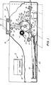
- FIG. 1 of the drawings there is shown by way of example an automatic xerographic reproduction or printing machine, designated generally by the numeral 10 incorporating a heat and pressure fuser apparatus 99 of the present invention.
- the reproduction machine 10 depicted in Figure 1 illustrates the various components utilized in machines of this type for producing copies of a document original 14.
- the apparatus 99 of the present invention is particularly well adapted for use in reproduction machine 10, it should become evident from the following description that it is equally well suited for use in a wide variety of other reproduction and printing machine types and systems and is not necessarily limited in application to the particular embodiments shown herein.
- Reproduction machine 10 has an image recording photoreceptor 15 in the form of a drum, the outer periphery of which has a suitable photoconductive material 16.
- Photoreceptor 15 is suitably journaled for rotation within the machine frame (not shown) as by means of shaft 17.
- a main drive motor 19 is drivingly coupled to photoreceptor 15, motor 19 rotating photoreceptor 15 in the direction indicated by arrow 18 to ring the photoconductive surface 16 of photoreceptor 15 past a series of xerographic processing stations.
- a suitable controller 21 with microprocessor 22 and memory 23 is provided for operating in predetermined timed relationship the various components that comprise machine 10 to reproduce the document original 14 upon a sheet of final support material such as copy sheet 20.
- memory 23 may comprise suitable read only memory (ROM), random access memory (RAM), and/or non-volatile memory (NVM), memory 23 serving to store the various operating parameters for reproduction machine 10 and the copy run information programmed by the machine user or operator.
- ROM read only memory
- RAM random access memory
- NVM non-volatile memory
- the photoconductive surface 16 of photoreceptor 15 is uniformly charged by a suitable charging device such as scorotron 25 at charging station 24.
- the uniformly charged photoconductive surface 16 is exposed at exposure station 26 to create a latent electrostatic image of the document original 14 on photoreceptor 15.
- a suitable supporting surface or platen 28 for document original 14 is provided having a scan aperture or slit 30 therethrough.
- a suitable document transport, depicted herein as inlet and outlet constant velocity roll pairs 32, 33 is provided for transporting the document original past scan slit 30.
- Roll pairs 32, 33 are drivingly coupled to main drive motor 19, roll pair 32 being coupled through an electromagnetically operated clutch 34.
- a suitable document sensor 31 is provided at the inlet to platen 28 for sensing the insertion of a document original 14 to be copied and initiating operation of the reproduction machine 10.
- a lamp 35 which is disposed below platen 28, serves to illuminate scan slit 30 and the line-like portion of the document original 14 thereover.
- a suitable fiber optic type lens array 37 which may, for example, comprise an array of gradient index fiber elements, is provided to optically transmit the image ray reflected from the line-like portion of the document original being scanned to the photoconductive surface 16 of photoreceptor 15 at exposure station 26.
- the latent image of the photoconductive surface 16 of photoreceptor 15 is developed at a development station 40.
- a suitable developer such as magnetic brush roll 41, which is drivingly coupled to main drive motor 19, brings a suitable developer mix in developer housing 43 into developing elevation with the latent image to develop the image and render the same visible.
- Copy sheets 20 are supported in stack-like fashion on base 44 of copy sheet supply tray 45. Suitable biasing means are provided to raise base 44 of tray 45 and bring the topmost copy sheet 20 in the stack of sheets 47 into operative relationship with segmented feed rolls 49. Feed rolls 49 are driven by main drive motor 19 through an electromagnetically operated clutch 51. Rolls 49 serve upon actuation of clutch 51 to feed the topmost copy sheet forward into the nip of a registration roll pair 50 which register the copy sheet with the image on the photoconductive surface 16 of photoreceptor 15. Registration roll pair 50 advance the copy sheet to transfer station 52. There, suitable transfer/detack means such as transfer/detaek corotrons 53, 54 bring the copy sheet into transfer relation with the developed image on photoconductive surface 16 and separate the copy sheet therefrom for fixing and discharge as a finished copy.
- suitable transfer/detack means such as transfer/detaek corotrons 53, 54 bring the copy sheet into transfer relation with the developed image on photoconductive surface 16 and separate the copy sheet therefrom for fixing and discharge as
- the image bearing copy sheet is transported to fuser 57 where the image is permanently fixed to the copy sheet.
- the finished copy is transported by roll pair 56 to a suitable receptacle such as an output tray (not shown).
- Registration roll pair 50 and transport roll pair 56 are driven by main drive motor 19 through suitable driving means such as belts and pulleys.
- drum type photoreceptor While a drum type photoreceptor is shown and described herein, it will be understood that other photoreceptor types may be employed such as belt, web, etc.
- An erase device 69 is provided for this purpose.
- the cleaning blade 63 is supported in contact with the photoreceptor 15 such that residual toner is chiselled therefrom.
- the toner and debris that are removed from the photoreceptor 15 fall into the collector 64 and are transported by means of an auger 72 disposed in the bottom of the collector 64. It is moved toward the back of the machine where it falls through an opening in the bottom of the collector 64.
- the residual toner and debris fall downwardly via conduit 71 into a receptacle (not shown) which serves to store the residual toner until the receptacle is full after which it is removed from the machine.
- the fuser apparatus 57 shown in more detail therein comprises a relatively thin fuser belt structure 80 comprising a base member 82 preferably fabricated from a metal material which is sufficiently stiff to be dragged across a non-rotating mandrel.
- the base member is fabricated from nickel by a conventional electroforming process which provides a uniform thickness in the order 50 - 76 ⁇ m (of 2-3 mils).
- the outer surface of the base member is coated with a conformable layer 85 which preferably comprises silicone rubber.
- the inner surface of the base member 82 is preferably coated with a low friction material 84 such as polytetrafluoroethylene commonly known by the tradename Teflon (registered trademark of E. I. DuPont).
- the thickness of the conformable layer is preferably at least 120 pm (5 mils).
- the belt structure is heated by a radiant heater 86 to a temperature suitable for fusing toner images carried by copy sheets 20.
- the radiant heater 86 is positioned at a predetermined distance away from a nip area 88 through which the copy sheets pass with the conformable layer 85 contacting the toner images on the sheets. This distance between the nip area and the nip is such that the heated portion of the belt contacts the toner images before the temperature of the belt has time to drop to a non-fusing temperature.
- a rigid pressure rod 90 for creating the required pressure in the nip area.
- the rod 90 is supported in engagement with one of two mandrels 92 and 94 about which the belt is entrained.
- a suitable force applying device such as a cam 96 is provided for effecting pressure engagement of the rod 90 and the mandrel 92 which, in turn, cooperate with pressure roll 100 to create the desired pressure on the belt and toner images sandwiched between the mandrel 92 and the pressure roll.
- the cam is designed to apply a loading in the nip area 88 of approximately 90 kg (200 pounds) or 4.8-6.9 x 10 5 Pa(70-100 PSI).
- a suitable drive train represented schematically by the reference character 101 serves to drive the pressure roll 100 which, in turn, frictionally effects movement of the belt about the mandrels.
- the drive 101 also effects operation of the cam 96.
- the belt structure 80 and radiant fuser 86 form a low (i.e. less than 150 grams and preferably 80 grams) mass fuser which can be elevated to an operating level in 6-8 seconds while operating at fusing speeds from 25-30 cms (10-12 in/sec) or any other desired speed.
- the power rating of the radiant energy source 86 is in the order of 1500-2000 watts.
- the belt structure in its non-tensioned condition has a diameter of 6.4 cm (2-1/2 inches) and a width of 33 cm (13 inches) or greater.
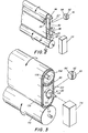
- a further embodiment of our fuser apparatus shown in Figure 3 and represented by reference character 99 comprises a similar fuser belt structure 80.
- the belt structure is entrained about a stationary mandrel 102 and a thin-walled, rotationally supported tube heater 104, the latter of which has an internal source of energy 106 for elevating the temperature of the belt.
- the geometry of the mandrel 102 is such that it limits deflection of the belt structure 80.
- a nip 108 is formed between the belt surface and a pressure roll 110.
- the mandrel has appended thereto a plurality of insulating nubs 112 to minimize the heat loss from the belt.
- Rotation of the pressure roll in a manner similar to that for rotating conventional roll fusers causes the belt to move about the mandrel whereby a heated portion of the belt is brought into the nip for fusing in toner images.
- the belt structure, tube heater 104, and the internal heat source 106 form low mass fuser.
- a suitable structure (not shown) effects proper tracking of the belt structure 80.
- the tube heater 104 is preferably fabricated from nickel and has a thickness of approximately 100 pm (four mils).
- the preferred method of forming the tube heater is by the electroforming process.
- a structure that is relatively rigid and substantially uniform in thickness is provided. Since the tube heater rotates, sliding friction between the belt structure and the tube heater is avoided when movement of the belt structure is effected by the pressure roll.
- the pressure roll in both embodiments of the invention has an outside diameter of 7.6 cm (three inches).
- the outer surface of the pressure roll is provided with a relatively thick conformable layer which may comprise silicone rubber.
- Bearings (not shown) support the tube heater for rotation by means of a drive schematically represented by reference character 116.
- the drive 116 also serves to actuate a cam 118 which acts on a cam follower 120 for applying a load on the mandrel 102 for creating desired nip pressures.
- the fuser apparatus representing our invention can be operated at relatively high (i.e. 25-30 cms (10-12 inches/sec.)) speeds without the use of standby power.
Abstract
A heat and pressure fusing apparatus (99) for fixing toner images in which the heat and pressure functions are effected at different locations on a thin, low mass flexible belt (80) forming the toner contacting surface. A pressure roll (110) cooperates with a stationary mandrel (102) to form a nip through which the belt and substrate pass simultaneously. The belt is heated by a remote source (104, 106; 86) such that by the time it passes through the nip it's temperature together with the applied pressure is sufficient for fusing the toner images passing therethrough. Preferably the belt comprises an electroformed nickel base having a conformable layer (e.g. silicone rubber) (85) on the side facing roll (110) and a low firction coating (e.g. PTFE) (84) on the opposite side contacting the mandrel (102).
Description
- This invention relates to a heat and pressure fuser apparatus for fixing powder images to substrates.
- In the art of xerography or other similar image reproducing arts, a latent electrostatic image is formed on a charge-retentive surface which may comprise a photoconductor which generally comprises a photoconductive insulating material adhered to a conductive backing. When the image is formed on a photoconductor, the photoconductor is first provided with a uniform charge after which it is exposed to a light image of an original document to be reproduced. The latent electrostatic images, thus formed, are rendered visible by applying any one of numerous pigmented resins specifically designed for this purpose.
- It should be understood that for the purposes of the present invention, which relates to fixing, i.e. rendering permanent, powder or toner images, the latent electrostatic image may be formed by means other than by the exposure of an electrostatically charged photosensitive member to a light image of an original document. For example, the latent electrostatic image may be generated from information electronically stored or generated, and the digital information may be converted to alphanumeric images by image generation electronics and optics.
- In the case of a reusable photoconductive surface, the pigmented resin, more commonly referred to as toner which forms the visible images is transferred to a substrate such as plain paper. After transfer the images are made to adhere to the substrate by a fuser apparatus. To date, the use of simultaneous heat and contact pressure for fusing toner images has been the most widely accepted commercially. Heretofore, it has been necessary with the foregoing type of fuser to heat the fuser not only when images are being fused but also during standby when images are not being fused. This is because of the long delay that would be required to elevate the fuser to a proper operating temperature if the heat supply were turned off during standby, the long delay being due to the relatively large mass that has to be brought up to the fusing temperature. Such delays would not be tolerated by the user even though operating the fuser in such a manner would eliminate a substantial waste of energy and therefore money. Along with this saving of energy, there would also be a reduction in heat loading to the environment.
- Elimination of fuser standby power has been accomplished in prior art devices such as flash fusers and cold pressure fusers. Both of these types of fusers, however, exhibit other drawbacks. For example, cold pressure fusers exhibit poor quality images. Flash fuser create undesirable effluents and they work very poorly with colored toners, especially the lighter colored ones. Also, the optical density of flash fused images is unsatisfactory.
- The present invention as recited in the accompanying claims provides a heat and pressure fuser that can be satisfactorily operated without the employment of standby power.
- An important aspect of the present invention lies in the separation of the heat and pressure functions. By separating the two functions it is possible to optimize each of them whereas if, as in prior art devices, they are integrated, design criteria that must be satisfied for optimum heating of the belt are counter-productive to optimization of the pressure function and vise versa. For example, in an integrated arrangement, since pressure creating application requires a relatively large rigid mass the heating of such a mass would require standby energy to be used in order to minimize the total time required for making copies. On the other hand, if the mass is substantially reduced in order to accommodate fast heating then the requisite mass for applying the required pressure would not be present.
- Embodiments of the invention will now be described, by way of example, with reference to the accompanying drawings, in which:-
- Figure 1 is a side view depicting a xerographic reproduction machine or printer of the type adapted to incorporate the present invention;
- Figure 2 is a perspective view of one embodiment of a fuser apparatus incorporating the inventive features of the invention; and
- Figure 3 is a side elevational view of a preferred embodiment of a fuser apparatus incorporating the inventive features of the invention.
- Referring to Figure 1 of the drawings, there is shown by way of example an automatic xerographic reproduction or printing machine, designated generally by the
numeral 10 incorporating a heat andpressure fuser apparatus 99 of the present invention. - The
reproduction machine 10 depicted in Figure 1 illustrates the various components utilized in machines of this type for producing copies of a document original 14. Although theapparatus 99 of the present invention is particularly well adapted for use inreproduction machine 10, it should become evident from the following description that it is equally well suited for use in a wide variety of other reproduction and printing machine types and systems and is not necessarily limited in application to the particular embodiments shown herein. -
Reproduction machine 10 has an image recordingphotoreceptor 15 in the form of a drum, the outer periphery of which has a suitable photoconductive material 16.Photoreceptor 15 is suitably journaled for rotation within the machine frame (not shown) as by means of shaft 17. Amain drive motor 19 is drivingly coupled tophotoreceptor 15,motor 19 rotatingphotoreceptor 15 in the direction indicated byarrow 18 to ring the photoconductive surface 16 ofphotoreceptor 15 past a series of xerographic processing stations. Asuitable controller 21 withmicroprocessor 22 andmemory 23 is provided for operating in predetermined timed relationship the various components that comprisemachine 10 to reproduce the document original 14 upon a sheet of final support material such ascopy sheet 20. As will be understood by those familiar with the art,memory 23 may comprise suitable read only memory (ROM), random access memory (RAM), and/or non-volatile memory (NVM),memory 23 serving to store the various operating parameters forreproduction machine 10 and the copy run information programmed by the machine user or operator. - Initially, the photoconductive surface 16 of
photoreceptor 15 is uniformly charged by a suitable charging device such asscorotron 25 atcharging station 24. The uniformly charged photoconductive surface 16 is exposed atexposure station 26 to create a latent electrostatic image of the document original 14 onphotoreceptor 15. For this purpose, a suitable supporting surface orplaten 28 for document original 14 is provided having a scan aperture or slit 30 therethrough. A suitable document transport, depicted herein as inlet and outlet constantvelocity roll pairs past scan slit 30.Roll pairs main drive motor 19,roll pair 32 being coupled through an electromagnetically operatedclutch 34. A suitable document sensor 31 is provided at the inlet toplaten 28 for sensing the insertion of a document original 14 to be copied and initiating operation of thereproduction machine 10. - A
lamp 35, which is disposed belowplaten 28, serves to illuminatescan slit 30 and the line-like portion of the document original 14 thereover. A suitable fiber optictype lens array 37, which may, for example, comprise an array of gradient index fiber elements, is provided to optically transmit the image ray reflected from the line-like portion of the document original being scanned to the photoconductive surface 16 ofphotoreceptor 15 atexposure station 26. - Following exposure, the latent image of the photoconductive surface 16 of
photoreceptor 15 is developed at a development station 40. There, a suitable developer such asmagnetic brush roll 41, which is drivingly coupled tomain drive motor 19, brings a suitable developer mix indeveloper housing 43 into developing elevation with the latent image to develop the image and render the same visible. -
Copy sheets 20 are supported in stack-like fashion onbase 44 of copysheet supply tray 45. Suitable biasing means are provided to raisebase 44 oftray 45 and bring thetopmost copy sheet 20 in the stack ofsheets 47 into operative relationship with segmented feed rolls 49. Feed rolls 49 are driven bymain drive motor 19 through an electromagnetically operatedclutch 51. Rolls 49 serve upon actuation ofclutch 51 to feed the topmost copy sheet forward into the nip of a registration roll pair 50 which register the copy sheet with the image on the photoconductive surface 16 ofphotoreceptor 15. Registration roll pair 50 advance the copy sheet totransfer station 52. There, suitable transfer/detack means such as transfer/detaek corotrons - Following
transfer station 52, the image bearing copy sheet is transported to fuser 57 where the image is permanently fixed to the copy sheet. Following fusing, the finished copy is transported byroll pair 56 to a suitable receptacle such as an output tray (not shown). Registration roll pair 50 andtransport roll pair 56 are driven bymain drive motor 19 through suitable driving means such as belts and pulleys. - Following transfer, residual developer remaining on the photoconductive surface 16 of
photoreceptor 15 is removed atcleaning station 62 by means ofcleaning blade 63. Developer removed byblade 63 is deposited into asuitable collector 64 for removal. - While a drum type photoreceptor is shown and described herein, it will be understood that other photoreceptor types may be employed such as belt, web, etc.
- To permit effective and controlled charging of the photoconductive surface 16 by
scorotron 25 to a predetermined level necessitates that any residual charges on the photoconductive surface 16 or trapped in the photoreceptor be removed prior to charging. Anerase device 69 is provided for this purpose. - At the
cleaning station 62, thecleaning blade 63 is supported in contact with thephotoreceptor 15 such that residual toner is chiselled therefrom. - The toner and debris that are removed from the
photoreceptor 15 fall into thecollector 64 and are transported by means of anauger 72 disposed in the bottom of thecollector 64. It is moved toward the back of the machine where it falls through an opening in the bottom of thecollector 64. The residual toner and debris fall downwardly viaconduit 71 into a receptacle (not shown) which serves to store the residual toner until the receptacle is full after which it is removed from the machine. - Referring to Figure 2, the
fuser apparatus 57 shown in more detail therein comprises a relatively thinfuser belt structure 80 comprising abase member 82 preferably fabricated from a metal material which is sufficiently stiff to be dragged across a non-rotating mandrel. To this end, the base member is fabricated from nickel by a conventional electroforming process which provides a uniform thickness in the order 50 - 76 µm (of 2-3 mils). The outer surface of the base member is coated with aconformable layer 85 which preferably comprises silicone rubber. The inner surface of thebase member 82 is preferably coated with alow friction material 84 such as polytetrafluoroethylene commonly known by the tradename Teflon (registered trademark of E. I. DuPont). The thickness of the conformable layer is preferably at least 120 pm (5 mils). - The belt structure is heated by a
radiant heater 86 to a temperature suitable for fusing toner images carried bycopy sheets 20. Theradiant heater 86 is positioned at a predetermined distance away from anip area 88 through which the copy sheets pass with theconformable layer 85 contacting the toner images on the sheets. This distance between the nip area and the nip is such that the heated portion of the belt contacts the toner images before the temperature of the belt has time to drop to a non-fusing temperature. - Because the belt structure is relatively thin, it is incapable of creating adequate nip pressures for fusing by the simultaneous application of heat and pressure. Accordingly, there is provided a
rigid pressure rod 90 for creating the required pressure in the nip area. Therod 90 is supported in engagement with one of twomandrels cam 96 is provided for effecting pressure engagement of therod 90 and themandrel 92 which, in turn, cooperate with pressure roll 100 to create the desired pressure on the belt and toner images sandwiched between themandrel 92 and the pressure roll. The cam is designed to apply a loading in thenip area 88 of approximately 90 kg (200 pounds) or 4.8-6.9 x 10⁵ Pa(70-100 PSI). A suitable drive train represented schematically by thereference character 101 serves to drive the pressure roll 100 which, in turn, frictionally effects movement of the belt about the mandrels. Thedrive 101 also effects operation of thecam 96. - The
belt structure 80 andradiant fuser 86 form a low (i.e. less than 150 grams and preferably 80 grams) mass fuser which can be elevated to an operating level in 6-8 seconds while operating at fusing speeds from 25-30 cms (10-12 in/sec) or any other desired speed. For such operating conditions, the power rating of theradiant energy source 86 is in the order of 1500-2000 watts. The belt structure in its non-tensioned condition has a diameter of 6.4 cm (2-1/2 inches) and a width of 33 cm (13 inches) or greater. - A further embodiment of our fuser apparatus shown in Figure 3 and represented by
reference character 99 comprises a similarfuser belt structure 80. In this case the belt structure is entrained about astationary mandrel 102 and a thin-walled, rotationally supportedtube heater 104, the latter of which has an internal source ofenergy 106 for elevating the temperature of the belt. The geometry of themandrel 102 is such that it limits deflection of thebelt structure 80. Anip 108 is formed between the belt surface and apressure roll 110. The mandrel has appended thereto a plurality of insulatingnubs 112 to minimize the heat loss from the belt. Rotation of the pressure roll in a manner similar to that for rotating conventional roll fusers causes the belt to move about the mandrel whereby a heated portion of the belt is brought into the nip for fusing in toner images. In this embodiment, the belt structure,tube heater 104, and theinternal heat source 106 form low mass fuser. A suitable structure (not shown) effects proper tracking of thebelt structure 80. - The
tube heater 104 is preferably fabricated from nickel and has a thickness of approximately 100 pm (four mils). The preferred method of forming the tube heater is by the electroforming process. Thus, a structure that is relatively rigid and substantially uniform in thickness is provided. Since the tube heater rotates, sliding friction between the belt structure and the tube heater is avoided when movement of the belt structure is effected by the pressure roll. The pressure roll in both embodiments of the invention has an outside diameter of 7.6 cm (three inches). The outer surface of the pressure roll is provided with a relatively thick conformable layer which may comprise silicone rubber. Bearings (not shown) support the tube heater for rotation by means of a drive schematically represented byreference character 116. Thedrive 116 also serves to actuate acam 118 which acts on acam follower 120 for applying a load on themandrel 102 for creating desired nip pressures. - As may now be appreciated from the foregoing, by separating the heating and pressure application functions we have provided a fuser that has a very fast warmup time. Consequently, the fuser apparatus representing our invention can be operated at relatively high (i.e. 25-30 cms (10-12 inches/sec.)) speeds without the use of standby power.
Claims (10)
1. Heat and pressure fuser apparatus for fixing powder images to substrates, characterized by
a low mass endless belt structure;
means cooperating to form a nip with said belt structure and simultaneously apply pressure to said belt structure;
means remote from said pressure applying means for elevating the temperature of said belt whereby said powder images are simultaneously subjected to heat and pressure as said substrates pass through said nip, said means for elevating the temperature of said belt being in contact with said belt; and
means for effecting movement of said belt structure at said nip.
2. Apparatus according to Claim 1 wherein said means for elevating the temperature of said belt structure comprises a rotatable low mass tubular member having a source of energy disposed internally thereof.
3. Apparatus according to Claim 2 wherein said low mass tubular member has a thickness of approximately 100 pm (4 mils).
4. Apparatus according to any preceding Claim wherein said means cooperating to apply pressure to said belt structure comprises a non-rotating mandrel.
5. Apparatus according to Claim 4 wherein the geometry of the mandrel is such as to limit deflection of said belt structure.
6. Apparatus according to Claim 4 or 5 including means disposed intermediate said belt structure and said non-rotating mandrel for minimizing the transfer of heat from the former to the latter.
7. Apparatus according to any preceding claim wherein the belt structure comprises a base member provided with a conformable layer on the side facing the cooperating means, and a low friction coating on the other side thereof.
8. Apparatus according to Claim 7 wherein said base member is fabricated from electroformed nickel.
9. Apparatus according to any preceding claim wherein said means for elevating the temperature of said belt structure is positioned relative to said nip so that sufficient time is allowed for elevating the temperature of said belt structure.
10. Apparatus according to any preceding claim wherein said means for effecting movement of said belt structure comprises means for effecting rotation of said pressure roll.
Applications Claiming Priority (2)
| Application Number | Priority Date | Filing Date | Title |
|---|---|---|---|
| US66659684A | 1984-10-31 | 1984-10-31 | |
| US666596 | 1984-10-31 |
Publications (1)
| Publication Number | Publication Date |
|---|---|
| EP0181723A1 true EP0181723A1 (en) | 1986-05-21 |
Family
ID=24674670
Family Applications (1)
| Application Number | Title | Priority Date | Filing Date |
|---|---|---|---|
| EP85307764A Withdrawn EP0181723A1 (en) | 1984-10-31 | 1985-10-28 | Low mass heat and pressure fuser |
Country Status (3)
| Country | Link |
|---|---|
| EP (1) | EP0181723A1 (en) |
| JP (1) | JPS61109083A (en) |
| BR (1) | BR8505413A (en) |
Cited By (10)
| Publication number | Priority date | Publication date | Assignee | Title |
|---|---|---|---|---|
| EP0411588A2 (en) * | 1989-08-01 | 1991-02-06 | Canon Kabushiki Kaisha | An image fixing apparatus |
| EP0461596A2 (en) * | 1990-06-11 | 1991-12-18 | Canon Kabushiki Kaisha | Heating apparatus using endless film |
| US5157238A (en) * | 1988-09-08 | 1992-10-20 | Spectrum Sciences, B.V. | Fusing apparatus and method |
| US5280155A (en) * | 1991-07-19 | 1994-01-18 | Canon Kabushihi Kaisha | Image heater having film guide with projections |
| US5636349A (en) * | 1988-09-08 | 1997-06-03 | Indigo N.V. | Method and apparatus for imaging using an intermediate transfer member |
| US5745829A (en) | 1989-01-04 | 1998-04-28 | Indigo N.V. | Imaging apparatus and intermediate transfer blanket therefor |
| US5815783A (en) * | 1989-12-06 | 1998-09-29 | Indigo N.V. | Method and apparatus for printing on both sides of a substrate |
| EP0935176A2 (en) * | 1998-02-09 | 1999-08-11 | Nitto Kogyo Co., Ltd. | Toner image fixing apparatus |
| EP0935175A2 (en) * | 1998-02-09 | 1999-08-11 | Nitto Kogyo Co., Ltd. | Toner image fixing apparatus |
| GB2357461A (en) * | 1999-12-22 | 2001-06-27 | Matsushita Electric Ind Co Ltd | Fixing devices for image processing devices |
Families Citing this family (6)
| Publication number | Priority date | Publication date | Assignee | Title |
|---|---|---|---|---|
| JPH07122771B2 (en) * | 1988-11-11 | 1995-12-25 | キヤノン株式会社 | Fixing device |
| JPH07122770B2 (en) * | 1988-11-11 | 1995-12-25 | キヤノン株式会社 | Fixing device |
| JPH0810375B2 (en) * | 1989-04-12 | 1996-01-31 | キヤノン株式会社 | Fixing device |
| JPH0810376B2 (en) * | 1989-06-22 | 1996-01-31 | キヤノン株式会社 | Fixing device |
| JPH0810377B2 (en) * | 1989-06-22 | 1996-01-31 | キヤノン株式会社 | Fixing device and fixing resin film |
| JPH04166966A (en) * | 1990-10-31 | 1992-06-12 | Babcock Hitachi Kk | Thermal fixing device |
Citations (7)
| Publication number | Priority date | Publication date | Assignee | Title |
|---|---|---|---|---|
| US3716018A (en) * | 1969-10-09 | 1973-02-13 | Ricoh Kk | Device for heating and fixing toner images upon a recording medium |
| US3811828A (en) * | 1970-10-29 | 1974-05-21 | Ricoh Kk | Process and device for heating and fixing an image upon a recording medium |
| GB2007159A (en) * | 1977-10-31 | 1979-05-16 | Oce Van Der Grinten Nv | Electrophotographic Fixing |
| GB2027640A (en) * | 1978-08-07 | 1980-02-27 | Pitney Bowes Inc | Apparatus for fixing toner images |
| US4242566A (en) * | 1980-03-21 | 1980-12-30 | Pitney Bowes Inc. | Heat-pressure fusing device |
| GB2050943A (en) * | 1979-05-16 | 1981-01-14 | Pitney Bowes Inc | Fusing device for electgrostatic copier |
| US4430406A (en) * | 1981-10-22 | 1984-02-07 | Eastman Kodak Company | Fuser member |
-
1985
- 1985-10-16 JP JP23091285A patent/JPS61109083A/en active Pending
- 1985-10-28 EP EP85307764A patent/EP0181723A1/en not_active Withdrawn
- 1985-10-30 BR BR8505413A patent/BR8505413A/en unknown
Patent Citations (7)
| Publication number | Priority date | Publication date | Assignee | Title |
|---|---|---|---|---|
| US3716018A (en) * | 1969-10-09 | 1973-02-13 | Ricoh Kk | Device for heating and fixing toner images upon a recording medium |
| US3811828A (en) * | 1970-10-29 | 1974-05-21 | Ricoh Kk | Process and device for heating and fixing an image upon a recording medium |
| GB2007159A (en) * | 1977-10-31 | 1979-05-16 | Oce Van Der Grinten Nv | Electrophotographic Fixing |
| GB2027640A (en) * | 1978-08-07 | 1980-02-27 | Pitney Bowes Inc | Apparatus for fixing toner images |
| GB2050943A (en) * | 1979-05-16 | 1981-01-14 | Pitney Bowes Inc | Fusing device for electgrostatic copier |
| US4242566A (en) * | 1980-03-21 | 1980-12-30 | Pitney Bowes Inc. | Heat-pressure fusing device |
| US4430406A (en) * | 1981-10-22 | 1984-02-07 | Eastman Kodak Company | Fuser member |
Cited By (17)
| Publication number | Priority date | Publication date | Assignee | Title |
|---|---|---|---|---|
| US5157238A (en) * | 1988-09-08 | 1992-10-20 | Spectrum Sciences, B.V. | Fusing apparatus and method |
| US5636349A (en) * | 1988-09-08 | 1997-06-03 | Indigo N.V. | Method and apparatus for imaging using an intermediate transfer member |
| US5745829A (en) | 1989-01-04 | 1998-04-28 | Indigo N.V. | Imaging apparatus and intermediate transfer blanket therefor |
| US5235395A (en) * | 1989-08-01 | 1993-08-10 | Canon Kabushiki Kaisha | Image fixing apparatus |
| EP0411588A2 (en) * | 1989-08-01 | 1991-02-06 | Canon Kabushiki Kaisha | An image fixing apparatus |
| EP0411588A3 (en) * | 1989-08-01 | 1991-07-10 | Canon Kabushiki Kaisha | An image fixing apparatus |
| US5815783A (en) * | 1989-12-06 | 1998-09-29 | Indigo N.V. | Method and apparatus for printing on both sides of a substrate |
| EP0461596A3 (en) * | 1990-06-11 | 1994-02-09 | Canon Kk | |
| EP0461596A2 (en) * | 1990-06-11 | 1991-12-18 | Canon Kabushiki Kaisha | Heating apparatus using endless film |
| US5280155A (en) * | 1991-07-19 | 1994-01-18 | Canon Kabushihi Kaisha | Image heater having film guide with projections |
| EP0935176A2 (en) * | 1998-02-09 | 1999-08-11 | Nitto Kogyo Co., Ltd. | Toner image fixing apparatus |
| EP0935175A2 (en) * | 1998-02-09 | 1999-08-11 | Nitto Kogyo Co., Ltd. | Toner image fixing apparatus |
| EP0935175A3 (en) * | 1998-02-09 | 1999-10-27 | Nitto Kogyo Co., Ltd. | Toner image fixing apparatus |
| EP0935176A3 (en) * | 1998-02-09 | 1999-10-27 | Nitto Kogyo Co., Ltd. | Toner image fixing apparatus |
| GB2357461A (en) * | 1999-12-22 | 2001-06-27 | Matsushita Electric Ind Co Ltd | Fixing devices for image processing devices |
| GB2357461B (en) * | 1999-12-22 | 2002-05-08 | Matsushita Electric Ind Co Ltd | Fixing device |
| US6449457B2 (en) | 1999-12-22 | 2002-09-10 | Matsushita Electric Industrial Co., Ltd. | Toner image forming device with belt heated by electromagnetic induction heating |
Also Published As
| Publication number | Publication date |
|---|---|
| BR8505413A (en) | 1986-08-05 |
| JPS61109083A (en) | 1986-05-27 |
Similar Documents
| Publication | Publication Date | Title |
|---|---|---|
| US4565439A (en) | Low mass heat and pressure fuser | |
| US4582416A (en) | Low mass heat and pressure fuser | |
| US4563073A (en) | Low mass heat and pressure fuser and release agent management system therefor | |
| US4242566A (en) | Heat-pressure fusing device | |
| EP0181723A1 (en) | Low mass heat and pressure fuser | |
| US5887235A (en) | Variable gloss fuser | |
| EP0046849A1 (en) | Hot roll fuser for a xerographic machine | |
| US5521688A (en) | Hybrid color fuser | |
| US4653897A (en) | Low mass conformable heat and pressure fuser | |
| US4008955A (en) | Fuser assembly for an electrophotograhic copying machine | |
| US3743403A (en) | Transport assembly | |
| US3965331A (en) | Dual mode roll fuser | |
| US5300994A (en) | Transfer system including a cam actuated segmented flexible transfer assist blade | |
| US6466764B2 (en) | Electrophotographic printer employing heated presser rollers to precondition print media | |
| US3856462A (en) | Reproduction machine fuser | |
| US3795441A (en) | Transfer roller | |
| US4335951A (en) | Fusing apparatus | |
| US5046146A (en) | Fuser system utilizing a reciprocating pressure web | |
| US4339194A (en) | Cold pressure fusing apparatus | |
| US4444486A (en) | Three-roll cold pressure fuse for fixing toner images to copy substrates including an overskewed roll | |
| US4860047A (en) | Fuser system utilizing a pressure web | |
| US3856461A (en) | Reproduction machine fuser | |
| US4859831A (en) | Fuser system | |
| US3770346A (en) | Method and apparatus for fuser assembly cooling in an electrostatographic machine | |
| US3987757A (en) | Paper handling improvements in radiant fuser via corrugation of paper |
Legal Events
| Date | Code | Title | Description |
|---|---|---|---|
| PUAI | Public reference made under article 153(3) epc to a published international application that has entered the european phase |
Free format text: ORIGINAL CODE: 0009012 |
|
| AK | Designated contracting states |
Kind code of ref document: A1 Designated state(s): DE FR GB |
|
| 17P | Request for examination filed |
Effective date: 19861103 |
|
| 17Q | First examination report despatched |
Effective date: 19880419 |
|
| STAA | Information on the status of an ep patent application or granted ep patent |
Free format text: STATUS: THE APPLICATION HAS BEEN WITHDRAWN |
|
| 18W | Application withdrawn |
Withdrawal date: 19881021 |
|
| RIN1 | Information on inventor provided before grant (corrected) |
Inventor name: FIELD, JOHN RALPH Inventor name: REYNOLDS, SCOTT DAVID |