EP0182087A1 - Circuit arrangement for collision detection - Google Patents
Circuit arrangement for collision detection Download PDFInfo
- Publication number
- EP0182087A1 EP0182087A1 EP85113021A EP85113021A EP0182087A1 EP 0182087 A1 EP0182087 A1 EP 0182087A1 EP 85113021 A EP85113021 A EP 85113021A EP 85113021 A EP85113021 A EP 85113021A EP 0182087 A1 EP0182087 A1 EP 0182087A1
- Authority
- EP
- European Patent Office
- Prior art keywords
- signal
- signal state
- bus line
- line system
- low
- Prior art date
- Legal status (The legal status is an assumption and is not a legal conclusion. Google has not performed a legal analysis and makes no representation as to the accuracy of the status listed.)
- Granted
Links
Images
Classifications
-
- H—ELECTRICITY
- H04—ELECTRIC COMMUNICATION TECHNIQUE
- H04L—TRANSMISSION OF DIGITAL INFORMATION, e.g. TELEGRAPHIC COMMUNICATION
- H04L12/00—Data switching networks
- H04L12/28—Data switching networks characterised by path configuration, e.g. LAN [Local Area Networks] or WAN [Wide Area Networks]
- H04L12/40—Bus networks
- H04L12/407—Bus networks with decentralised control
- H04L12/413—Bus networks with decentralised control with random access, e.g. carrier-sense multiple-access with collision detection (CSMA-CD)
- H04L12/4135—Bus networks with decentralised control with random access, e.g. carrier-sense multiple-access with collision detection (CSMA-CD) using bit-wise arbitration
Definitions
- bus line systems are often used, in which the respectively connected stations have optional access via transmitting and receiving devices (Random Access) to the bus line system.
- the digital signals emitted by a station are transmitted on both sides of the bus and are only picked up by the subscriber station (s) designated by the address (es) in accordance with the preceding addresses.
- CSMA / CD Carrier Sense Multiplex Access with Collision Oetection
- the station in question begins to transmit, initially "listening" until it is certain after a certain period of time (round trip delay time) that all the other stations have noticed their transmission. If another station has started to transmit at about the same time, both stations become one Detect their digital signals collide with those of the other station, whereupon they abort their transmission process in order to start again after a random period of time.
- the multiple transmission can be detected on the basis of a level increase occurring on the bus line system due to the addition of two signals, which, however, requires a relatively complex analog technology, in particular in the form of very precise symmetrical operational amplifiers (to be fed with two voltages).
- a simple method with which a multiple transmission can be recognized is that the active station compares the signal it is currently emitting (and emitted) with the signal state prevailing at its receiving device on the bus line system, one signal then distinguishing one Indicates collision.
- the detection of such a signal (state) difference presupposes that one signal state always asserts itself physically on the bus line system over the other signal state (in the case of binary signals).
- the detection can then take place in such a way that the transmission and reception signal states are scanned cyclically and then compared with one another, which is, however, associated with time gaps, on the basis of which an occurred collision and the like. May not be recognized.
- the object of the invention is to enable collision detection when a subscriber station accesses a bus line system using simple means and at the same time quickly and with high security.
- the invention relates to a circuit arrangement for collision detection when a subscriber station accesses a bus line system, to which the receiving devices and the two signal states, one of which forms a dominance signal state which prevails over the other signal state on the bus line system, are connected to 'transmitting devices of such subscriber stations Comparison of the transmission signal state just given in the subscriber station with the signal state currently prevailing on the bus line system, in particular bus system with two signal conductors and a line shield (ground); According to the invention, this circuit arrangement is characterized in that it detects an access collision in its transmitting device on the basis of a signal transition on the bus line system into the dominance signal state while the other signal state is ongoing.
- the invention which enables seamless collision detection in the context of a signal state comparison, can be designed such that an edge-controlled bistable flip-flop is provided, the set input of which is connected to a line of the subscriber station carrying the respective transmission signal, from the receiving device of which the clock input of the edge-controlled bistable is provided Tilting element is acted upon by a signal corresponding to the signal state given in each case on the bus line system.
- this known telecommunication system with the elimination of an otherwise given dominance of said one signal state caused by the increase in resistance, has a different path than the invention.
- a bus line system can preferably be formed by a shielded (twisted pair) cable having two twisted wires with a characteristic impedance of, for example, 150 ohms, the two twisted wires forming the signal conductors 1 'shown in the drawing, 1 "form.
- Transmitter devices S are connected to the two signal conductors 1 ', 1 "via two differential outputs s', s"; these transmitting devices S, together with receiving devices E also connected to the two signal conductors 1 ', 1 "via differential inputs +, - each belong to a subscriber station St, which is not shown in any more detail, for example a telecommunication terminal, a computer or a switching processor.
- the transmitting devices S each have a bus transmitter T provided with two differential outputs t ', t ", which is a tristate bus transmitter, for example of the type AM26LS31 (AMD) or SN74ALS1631 (TI) or can also be a bus transmitter of no such third state, for example of the type 9638 (Fairchild).
- the transmission devices S have two possible signal states, the signal state (given at a transmission device S) (e.g. a signal state LOW) being different from the signal state (given at another transmission device) (the signal state HIGH in the example) in the bus line system L. enforced, ie causes a dominance signal state in the transmission system.
- the transmission device S in question leaves the two signal conductors 1 1 , 1 "- and thus also the subscriber stations connected to them - at least approximately unloaded.
- each with a two differential outputs t ', t "having bus transmitters T formed transmission devices S which connect the two differential outputs t', t" to the two signal conductors 1 ', 1 "via two diodes D', D" in the mentioned other signal state (HIGH in the off state).
- these diodes which have a low forward voltage and a low forward resistance, switch the potentials occurring at the two bus transmitter outputs t 'and t "having a low internal resistance practically unchanged to the two signal conductors 1' and 1 "by, sc that there in the mentioned one signal state (LOW)
- the transmitting device S under consideration is in its other signal state (HIGH), in which a bus transmission potential of approximately 3.7 V in the example and a bus transmission potential of approximately 0.1 V occurs in the example at the bus transmitter output t 'and prevail nevertheless from another bus transmitter the previously specified potential ratios on the two signal conductors 1 'and 1 ", the two diodes D' and D" of the transmitter S under consideration are blocked, and now each have one at their two signal outputs s' and s " compared with the one signal state given in the case of diodes in the on state low internal resistance, large internal resistance, transmission device S leaves the two signal conductors 1 1 , 1 "practically unloaded, in other words, the transmission device S and the signal conductors 1 ', 1" are practically decoupled from one another.
- HIGH a bus transmission potential of approximately 3.7 V in the example and a bus transmission potential of approximately 0.1 V occurs in the example at the bus transmitter output t 'and prevail nevertheless from another bus transmitter the previously specified potential ratios on the
- the two signal conductors 1 ', 1 are connected to at least one voltage divider U-R1-R2-R3 ground, the internal resistance (R2
- this voltage divider lying between a potential U of 5 V and ground, can be constructed with two 330 ohm resistors R1, R3 and an intermediate 270-0hm resistor, with which it then has a potential of about 3 in the operating case under consideration. 2V to the signal conductor 1 1 and a potential of about 1.8 V to the signal conductor 1 ".
- an edge-controlled bistable JK flip-flop CD is provided in the subscriber station St outlined in the drawing, the set input J of which is connected to the input line t of the bus transmitter T carrying the respective transmission signal and its dynamic Clock input is connected to the output line e of the differential amplifier of the receiving device E; the clock input is thus each subjected to a signal corresponding to the signal state just given on the bus line system L.
- bistable flip-flop CD can be reset again via a reset input R when the bus access by station St ends, which, however, also need not be pursued here, since this is no longer necessary to understand the invention.
Abstract
Description
Für einen schnellen Austausch von Digitalsignalen zwischen häufig wechselnden Gegenstellen (Stationen), beispielsweise zwischen Telekommunikations-Terminals, zwischen einer Datenverarbeitung dienenden Rechnern oder auch zwischen vermittlungstechnischen Prozessoren, finden vielfach Busleitungssysteme Anwendung, in denen die jeweils angeschlossenen Stationen über Sende- und Empfangseinrichtungen einen wahlfreien Zugriff (Random Access) zu dem Busleitungssystem haben. Die dabei von einer Station ausgesendeten Digitalsignale werden auf dem Bus nach beiden Seiten hin übertragen und nach Maßgabe vorangestellter Adressen nur von der (den) durch die Adresse(n) bezeichneten Teilnehmerstation(en) aufgenommen. Für die Regelung des Zugriffs zum Busleitungssystem hat dabei besonders das sog. CSMA/CD-(Carrier Sense Multiplex Access with Collision Oetection)-Verfahren Bedeutung: Bevor eine Station zu senden beginnt, horcht sie in den Bus hinein, ob dort bereits ein Übertragungsvorgang stattfindet. Zutreffendenfalls wartet sie zunächst dessen Ende ab; dann beginnt die betreffende Station zu senden, wobei sie zunächst weiter "mithört", bis sie nach einer gewissen Zeitspanne (round trip delay time) sicher ist, daß alle anderen Stationen ihr Senden bemerken konnten. Hat in gleicher Weise eine andere Station etwa gleichzeitig zu senden begonnen, so werden beide Stationen eine Kollision ihrer Digitalsignale mit denen der jeweils anderen Station feststellen, woraufhin sie ihren Sendevorgang jeweils abbrechen, um nach einer Zufallszeitspanne damit erneut zu beginnen.For a rapid exchange of digital signals between frequently changing remote stations (stations), for example between telecommunications terminals, between computers used for data processing or between switching processors, bus line systems are often used, in which the respectively connected stations have optional access via transmitting and receiving devices (Random Access) to the bus line system. The digital signals emitted by a station are transmitted on both sides of the bus and are only picked up by the subscriber station (s) designated by the address (es) in accordance with the preceding addresses. The so-called CSMA / CD (Carrier Sense Multiplex Access with Collision Oetection) method is particularly important for controlling access to the bus line system: Before a station begins to transmit, it listens to the bus to determine whether a transmission process is already taking place there . If applicable, it first waits for its end; then the station in question begins to transmit, initially "listening" until it is certain after a certain period of time (round trip delay time) that all the other stations have noticed their transmission. If another station has started to transmit at about the same time, both stations become one Detect their digital signals collide with those of the other station, whereupon they abort their transmission process in order to start again after a random period of time.
Das Mehrfachsenden kann dabei an Hand einer auf dem Busleitungssystem auftretenden Pegelüberhöhung, bedingt durch die Addition zweier Signale, erkannt werden, was allerdings eine relativ aufwendige Analogtechnik, insbesondere in Form sehr genauer symmetrischer (mit zwei Spannungen zu speisender) Operationsverstärker erfordert.The multiple transmission can be detected on the basis of a level increase occurring on the bus line system due to the addition of two signals, which, however, requires a relatively complex analog technology, in particular in the form of very precise symmetrical operational amplifiers (to be fed with two voltages).
Eine einfache Methode, mit der ein Mehrfachsenden erkannt werden kann, besteht darin, daß die aktive Station das von ihr gerade abzugebende (und abgegebene) Signal mit dem an ihrer Empfangseinrichtung auf dem Busleitungssystem herrschenden Signalzustand vergleicht, wobei ein Signal(zustands)unterschied dann eine Kollision anzeigt. Die Erkennung eines solchen Signal(zustands)unterschiedes setzt voraus, daß sich auf dem Busleitungssystem der eine Signalzustand physikalisch stets gegenüber dem (bei Binärsignalen) anderen Signalzustand durchsetzt. Die Erkennung kann dann in der Weise geschehen, dass die Sende- und Empfangssignalzustände zyklisch abgetastet und danach miteinander verglichen werden, was indessen mit Zeitlücken verbunden ist, auf Grund derer eine eingetretene Kollision u. U. nicht erkannt wird.A simple method with which a multiple transmission can be recognized is that the active station compares the signal it is currently emitting (and emitted) with the signal state prevailing at its receiving device on the bus line system, one signal then distinguishing one Indicates collision. The detection of such a signal (state) difference presupposes that one signal state always asserts itself physically on the bus line system over the other signal state (in the case of binary signals). The detection can then take place in such a way that the transmission and reception signal states are scanned cyclically and then compared with one another, which is, however, associated with time gaps, on the basis of which an occurred collision and the like. May not be recognized.
Die Erfindung stellt sich demgegenüber die Aufgabe, eine Kollisionserkennung beim Zugriff einer Teilnehmerstation auf ein Busleitungssystem mit einfachen Mitteln und zugleich schnell und mit hoher Sicherheit zu ermöglichen.In contrast, the object of the invention is to enable collision detection when a subscriber station accesses a bus line system using simple means and at the same time quickly and with high security.
Die Erfindung betrifft eine Schaltungsanordnung zur Kollisionserkennung beim Zugriff einer Teilnehmerstation auf ein Busleitungssystem, an das die Empfangseinrichtungen und die zweier Signalzustände, deren einer einen gegenüber dem anderen Signalzustand auf dem Busleitungssystem sich durchsetzenden Dominanz-Signalzustand bildet,'fähigen Sendeeinrichtungen solcher Teilnehmerstationen angeschlossen sind, durch Vergleich des in der Teilnehmerstation gerade gegebenen Sendesignalzustandes mit dem auf dem Busleitungssystem, insbesondere Bussystem mit zwei Signalleitern und einem Leitungsschirm (Masse), gerade herrschenden Signalzustand; diese Schaltungsanordnung ist erfindungsgemäß dadurch gekennzeichnet, daß sie eine Zugriffskollision anhand eines auf dem Busleitungssystem vor sich gehenden Signalüberganges in den Dominanz-Signalzustand während eines Andauerns des anderen Signalzustands in ihrer Sendeeinrichtung feststellt.The invention relates to a circuit arrangement for collision detection when a subscriber station accesses a bus line system, to which the receiving devices and the two signal states, one of which forms a dominance signal state which prevails over the other signal state on the bus line system, are connected to 'transmitting devices of such subscriber stations Comparison of the transmission signal state just given in the subscriber station with the signal state currently prevailing on the bus line system, in particular bus system with two signal conductors and a line shield (ground); According to the invention, this circuit arrangement is characterized in that it detects an access collision in its transmitting device on the basis of a signal transition on the bus line system into the dominance signal state while the other signal state is ongoing.
Die Erfindung, die im Rahmen eines Signalszustandsvergleichs eine lückenlose Kollisionsdetektion ermöglicht, kann dabei vorzugseise so ausgestaltet sein, daß ein flankengesteuertes bistabiles Kippglied vorgesehen ist, dessen Setzeingang mit einer das jeweilige Sendesignal führenden Leitung der Teilnehmerstation verbunden ist, von deren Empfangseinrichtung der Takteingang des flankengesteuerten bistabilen Kippgliedes mit einem dem auf dem Busleitungssystem jeweils gegebenen Signalzustand entsprechenden Signal beaufschlagt ist.The invention, which enables seamless collision detection in the context of a signal state comparison, can be designed such that an edge-controlled bistable flip-flop is provided, the set input of which is connected to a line of the subscriber station carrying the respective transmission signal, from the receiving device of which the clock input of the edge-controlled bistable is provided Tilting element is acted upon by a signal corresponding to the signal state given in each case on the bus line system.
Es sei an dieser Stelle bemerkt, daß (aus EP-A-00 49 917) ein Telekommunikationssystem mit einem Bus bekannt ist, in welchem ein Telekommunikations-Terminal bei Abgabe eines dem einen Signalzustand entsprechenden Signals ("ß") zur Beseitigung einer sonst gegebenen Dominanz dieses Signalzustandes den Ausgangswiderstand seiner Sendeeinrichtung auf die Höhe des Busleitungs-Wellenwiderstands erhöht, wobei die Kollisionserkennung dann anhand des Empfangs eines dem anderen Signalzustand entsprechenden Signals ("1") während des Andauerns der Widerstandserhöhung geschieht.It should be noted at this point that (from EP-A-00 49 917) a telecommunication system with a bus is known in which a telecommunication terminal when a signal corresponding to a signal state ("β") is emitted to eliminate an otherwise given signal This signal state dominates the output resistance of its transmission device increased to the level of the bus line characteristic impedance, the collision detection then taking place on the basis of the reception of a signal corresponding to the other signal state (“1”) while the resistance increase continues.
Dieses bekannte Telekommunikationssystem weist mit der durch die Widerstandserhöhung bewirkten Beseitigung einer sonst gegebenen Dominanz des genannten einen Signalzustandes einen prinzipiell anderen Weg, als ihn die Erfindung geht.In principle, this known telecommunication system, with the elimination of an otherwise given dominance of said one signal state caused by the increase in resistance, has a different path than the invention.
Es sei außerdem bemerkt, daß es (aus US-A-44 09 592) bekannt ist, eine Kollision von Terminals beim Zugriff auf einen Bus daran zu erkennen, daß während eines am Ausgang einer Sendeeinrichtung vor sich gehenden Signalüberganges der bisherige Signalzustand, der an sich auf Grund von inneren Verzögerungen am Ausgang der zugehörigen Empfangseinrichtung noch andauern müßte, dort nicht mehr andauert.It should also be noted that it is known (from US-A-44 09 592) to recognize a collision of terminals when accessing a bus by the fact that during a signal transition going on at the output of a transmitting device, the previous signal state, the on should persist due to internal delays at the output of the associated receiving device, no longer persists there.
Eine solche Kollisionserkennung setzt allerdings entsprechende, hinreichend große innere Verzögerungen voraus, - eine Voraussetzung, von der man insbesondere angesichts des Strebens nach immer schnelleren Schaltungen nicht ohne weiteres ausgehen kann.Such a collision detection, however, requires corresponding, sufficiently large internal delays - a requirement which cannot be easily assumed, particularly in view of the striving for ever faster circuits.
Auf die Erfindung zurückkommend sei diese nun anhand der Zeichnung noch näher erläutert.Coming back to the invention, this will now be explained in more detail with reference to the drawing.
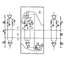
Die Zeichnung zeigt schematisch in einem zum Verständnis der Erfindung erforderlichen Umfange zunächst ein Bussystem L mit zwei Signaladern 1', 1" und einem in der Zeichnung nicht eigens dargestellten Leitungsschirm (Masse, Erde) , wie es auch schon an anderer Stelle (DE-P 34 26 900) beschrieben wird; ein solches Busleitungssystem kann vorzugsweise durch ein zwei verdrallte Adern aufweisendes geschirmtes (Twisted-Pair-)Kabel mit einem Wellenwiderstand von beispielsweise 150 Ohm gebildet sein, wobei die zwei verdrallten Adern die in der Zeichnung dargestellten Signalleiter 1', 1" bilden. An die beiden Signalleiter l', 1" sind jeweils über zwei Differenzausgänge s', s" Sendeeinrichtungen S angeschlossen; diese Sendeeinrichtungen S mögen zusammen mit über Differenzeingänge +, - ebenfalls an die beiden Signalleiter 1', 1" angeschlossenen Empfangseinrichtungen E jeweils zu einer im übrigen nicht näher dargestellten Teilnehmerstation St gehören, beispielsweise einem Telekommunikations-Endgerät, einem Rechner oder einem Vermittlungsprozessor. Die Sendeeinrichtungen S weisen jeweils einen mit zwei Differenzausgängen t', t" versehenen Bussender T auf, bei dem es sich um einen neben zwei Signalzuständen auch noch einen Ruhezustand als dritten Zustand aufweisenden Tristate-Bussender beispielsweise des Typs AM26LS31 (AMD) oder SN74ALS1631 (TI) oder auch um einen keinen solchen dritten Zustand aufweisenden Bussender beispielsweise des Typs 9638 (Fairchild) handeln kann. In jedem Falle haben die Sendeeinrichtungen S zwei mögliche Signalzustände, wobei der (bei einer Sendeeinrichtung S gegebene) eine Signalzustand (z.B. ein Signalzustand LOW) sich gegenüber dem (bei einer anderen Sendeeinrichtung gegebenen) anderen Signalzustand (im Beispiel der Signalzustand HIGH) im Busleitungssystem L durchsetzt, d.h. einen Dominanzsignalzustand im 5usleitungssystem bewirkt. In dem genannten anderen Signalzustand (HIGH) läßt die betreffende Sendeeinrichtung S die beiden Signalleiter 11, 1" - und damit auch die daran angeschlossenen Teilnehmerstationen - zumindest angenähert unbelastet. Hierzu sind in dem in der Zeichnung skizzierten Ausführungsbeispiel eines Busleitungssystems bei den jeweils mit einem zwei Differenzausgänge t', t" aufweisenden Bussender T gebildeten Sendeeinrichtungen S die zwei Differenzausgänge t', t" über zwei in dem genannten anderen Signalzustand (HIGH im Sperrzustand befindliche Dioden D', D" mit den zwei Signalleitern 1', 1" verbunden. Diese Dioden, die eine niedrige Durchlaßspannung und einen niedrigen Durchlaßwiderstand haben, schalten in dem genannten einen Signalzustand (LOW) die an den beiden einen niedrigen Innenwiderstand aufweisenden Bussender-Ausgängen t' und t" auftretenden Potentiale praktisch unverändert auf die beiden Signalleiter l' bzw. 1" durch, sc daß dort in dem genannten einen Signalzustand (LOW) die betreffenden Bussendepotentiale von beispielsweise etwa 0,9 V auf dem Signalleiter 1' und etwa 2,7 V auf dem Signalleiter 1" herrschen.The drawing shows schematically, in a scope necessary for understanding the invention, a bus system L with two
Befindet sich die gerade betrachtete Sendeeinrichtung S in ihrem anderen Signalzustand (HIGH), in dem am Bussenderausgang t' ein Bussendepotential von im Beispiel etwa 3,7 V und am Bussenderausgang t" ein Bussendepotential von im Beispiel etwa 0,1 V auftritt, und herrschen gleichwohl von einer anderen Bussendeeinrichtung her die zuvor angegebenen Potentialverhältnisse auf den beiden Signalleitern 1' und 1", so sind die beiden Dioden D' und D" dergerade betrachteten Sendeeinrichtung S gesperrt, und die jetzt an ihren beiden Signalausgängen s' und s" jeweils einen gegenüber dem bei dem genannten einen Signalzustand - bei im Durchlaßzustand befindlichen Dioden - gegebenen niedrigen Innenwiderstand großen Innenwiderstand aufweisende Sendeeinrichtung S läßt die beiden Signalleiter 11, 1" praktisch unbelastet, mit anderen Worten, die Sendeeinrichtung S und die Signalleiter 1', 1" sind praktisch'voneinander entkoppelt.The transmitting device S under consideration is in its other signal state (HIGH), in which a bus transmission potential of approximately 3.7 V in the example and a bus transmission potential of approximately 0.1 V occurs in the example at the bus transmitter output t 'and prevail nevertheless from another bus transmitter the previously specified potential ratios on the two
Damit auch dann, wenn sich gerade alle an das Busleitungssystem L angeschlossenen Sendeeinrichtungen in dem genannnten anderen Signalzustand (oder auch in einem dritten, Inaktiv-Zustand (Tristate)) befinden, auf den Signalleitern 1', 1" eine definierte Signalspannung auftritt, können, wie dies auch aus der Zeichnung ersichtlich wird, die beiden Signalleiter 1', 1" an zumindest einen Spannungsteiler U-R1-R2-R3 Masse angeschlossen sein, dessen Innenwiderstand (R2||(R1+R3)) groß gegenüber dem bei dem genannten einen Signalzustand gegebenen Innenwiderstand einer Sendeeinrichtung S ist. Dieser Spannungsteiler kann im Beispiel, zwischen einem Potential U von 5 V und Masse liegend, mit zwei 330-Ohm-Widerständen R1, R3 und einem dazwischenliegenden 270-0hm-Widerstand aufgebaut sein, womit er dann im betrachteten Betriebsfall ein Potential von etwa 3,2V an den Signalleiter 11 und ein Potential von etwa 1,8 V an den Signalleiter 1" anlegt.So that a defined signal voltage can occur on the
Die im Vorstehenden erläuterte Dominanz des einen Signalzustandes über den anderen macht es möglich, Zugriffskollisionen, d. h. ein gleichzeitiges Senden mehrerer Teilnehmerstationen St, durch Vergleich des in einer Teilnehmerstation gerade gegebenen Sendesignalzustandes mit dem auf dem Busleitungssystem L herrschenden Signalzustand festzustellen.The dominance of one signal state over the other explained above makes it possible to prevent access collisions, i. H. a simultaneous transmission of several subscriber stations St, by comparing the transmission signal state currently given in a subscriber station with the signal state prevailing on the bus line system L.
Hierzu ist in der in der Zeichnung skizzierten Teilnehmerstation St ein flankengesteuertes bistabiles JK-Kippglied CD vorgesehen, dessen Setzeingang J mit der das jeweilige Sendesignal führenden Eingangsleitung t des Bussenders T verbunden ist und dessen dynamischer Takteingang mit der Ausgangsleitung e des Differenzverstärkers der Empfangeinrichtung E verbunden ist; der Takteingang wird damit jeweils mit einem dem auf dem Busleitungssystem L gerade gegebenen Signalzustand entsprechenden Signal beaufschlagt.For this purpose, an edge-controlled bistable JK flip-flop CD is provided in the subscriber station St outlined in the drawing, the set input J of which is connected to the input line t of the bus transmitter T carrying the respective transmission signal and its dynamic Clock input is connected to the output line e of the differential amplifier of the receiving device E; the clock input is thus each subjected to a signal corresponding to the signal state just given on the bus line system L.
Kommt es nun auf dem Busleitungssystem L zu einem Signalübergang in den Dominanz-Signalzustand (LOW), so wird diese Signalzustandsänderung am Takteingang des bistabilen Kippgliedes CD wirksam. Dauert zugleich der andere Signalzustand (HIGH) auf der Leitung t der Sendeeinrichtung S und damit am J-Eingang des bistabilen Kippgliedes CD an, so wird das Kippglied CD gesetzt und gibt damit an seinem Ausgang cd ein einen Mehrfachzugriff zum Busleitungssystem L anzeigendes Kollisionssignal ab. Dieses Kollisionssignal kann dann in der Station St einen Abbruch des Sendevorgangs auslösen, was hier jedoch nicht weiter verfolgt zu werden braucht, da dies zum Verständnis der Erfindung nicht mehr erforderlich ist.If there is a signal transition to the dominance signal state (LOW) on the bus line system L, this signal state change becomes effective at the clock input of the bistable flip-flop CD. If at the same time the other signal state (HIGH) on the line t of the transmitting device S and thus at the J input of the bistable flip-flop CD, the flip-flop CD is set and thus outputs a collision signal indicating multiple access to the bus line system L at its output cd. This collision signal can then trigger an abort of the transmission process in station St, but this need not be pursued further here, since this is no longer necessary to understand the invention.
Abschließend sei noch bemerkt, daß das bistabile Kippglied CD bei Beendigung des Buszugriffs durch die Station St über einen Rücksetzeingang R wieder rückgesetzt werden kann, was hier indessen ebenfalls nicht weiter verfolgt zu werden braucht, da auch dies zum Verständnis der Erfindung nicht mehr erforderlich ist.Finally, it should also be noted that the bistable flip-flop CD can be reset again via a reset input R when the bus access by station St ends, which, however, also need not be pursued here, since this is no longer necessary to understand the invention.
Claims (2)
Priority Applications (1)
| Application Number | Priority Date | Filing Date | Title |
|---|---|---|---|
| AT85113021T ATE44341T1 (en) | 1984-10-16 | 1985-10-14 | CIRCUIT ARRANGEMENT FOR COLLISION DETECTION. |
Applications Claiming Priority (2)
| Application Number | Priority Date | Filing Date | Title |
|---|---|---|---|
| DE3437851 | 1984-10-16 | ||
| DE3437851 | 1984-10-16 |
Publications (2)
| Publication Number | Publication Date |
|---|---|
| EP0182087A1 true EP0182087A1 (en) | 1986-05-28 |
| EP0182087B1 EP0182087B1 (en) | 1989-06-28 |
Family
ID=6247990
Family Applications (1)
| Application Number | Title | Priority Date | Filing Date |
|---|---|---|---|
| EP85113021A Expired EP0182087B1 (en) | 1984-10-16 | 1985-10-14 | Circuit arrangement for collision detection |
Country Status (3)
| Country | Link |
|---|---|
| EP (1) | EP0182087B1 (en) |
| AT (1) | ATE44341T1 (en) |
| DE (1) | DE3571295D1 (en) |
Citations (2)
| Publication number | Priority date | Publication date | Assignee | Title |
|---|---|---|---|---|
| EP0049917A1 (en) * | 1980-10-02 | 1982-04-21 | Koninklijke Philips Electronics N.V. | Communication system and station suitable therefor |
| US4409592A (en) * | 1981-04-20 | 1983-10-11 | Hunt V Bruce | Multipoint packet data communication system using random access and collision detection techniques |
-
1985
- 1985-10-14 EP EP85113021A patent/EP0182087B1/en not_active Expired
- 1985-10-14 DE DE8585113021T patent/DE3571295D1/en not_active Expired
- 1985-10-14 AT AT85113021T patent/ATE44341T1/en not_active IP Right Cessation
Patent Citations (2)
| Publication number | Priority date | Publication date | Assignee | Title |
|---|---|---|---|---|
| EP0049917A1 (en) * | 1980-10-02 | 1982-04-21 | Koninklijke Philips Electronics N.V. | Communication system and station suitable therefor |
| US4409592A (en) * | 1981-04-20 | 1983-10-11 | Hunt V Bruce | Multipoint packet data communication system using random access and collision detection techniques |
Also Published As
| Publication number | Publication date |
|---|---|
| ATE44341T1 (en) | 1989-07-15 |
| EP0182087B1 (en) | 1989-06-28 |
| DE3571295D1 (en) | 1989-08-03 |
Similar Documents
| Publication | Publication Date | Title |
|---|---|---|
| EP0275464B1 (en) | Emitter-receiver device for a bus system | |
| DE2806179C2 (en) | Circuit arrangement for connecting transceivers to a coaxial line | |
| DE2633066C2 (en) | Device for the transmission of push-pull signals over a two-wire line in duplex mode | |
| DE2557896A1 (en) | MULTIPLE POINT DATA TRANSFER SYSTEM | |
| DE2049085B2 (en) | Circuit arrangement for the transmission of data between subscriber stations connected to a transmission line arrangement | |
| EP0274679B1 (en) | Emitter-receiver device for a bus system | |
| DE2537383C3 (en) | Circuit arrangement with a suitably terminated transmission line for the transmission of signals, in particular binary data signals | |
| EP0182087B1 (en) | Circuit arrangement for collision detection | |
| EP0171555B1 (en) | Bus system with two signal conductors connected to transmission devices via two differential outputs | |
| DE2156626A1 (en) | Electrical communication switching system | |
| EP0416679B1 (en) | Data transmission device with differential data transmission link | |
| DE3901589A1 (en) | CONNECTING A BUS PARTICIPANT | |
| DE602004011188T2 (en) | ARRANGEMENT FOR MASS SPREAD COMPENSATION IN A DATA BUSY SYSTEM | |
| DE1952549C3 (en) | Circuit arrangement for the transmission of pulses | |
| DE2642318C2 (en) | Circuit arrangement for feeding subscriber stations | |
| DE3205948A1 (en) | DATA COMMUNICATION SYSTEM | |
| EP0038509A1 (en) | Logic circuit to avoid a latch-up condition between distant data buses | |
| DE4434084C1 (en) | Noise elimination circuit for clock pulse sequence | |
| DE3112863A1 (en) | COLLECTIVE CHANNEL ARRANGEMENT FOR CONNECTING SEVERAL ELECTRICAL UNITS | |
| DE2103435C3 (en) | Method and circuit arrangement for preventing the transmission of binary characters at a higher than the highest permitted transmission speed | |
| DE3700284A1 (en) | Sending and receiving device for a bus line system | |
| DE1285524B (en) | Impulse transmission system | |
| DE2708671A1 (en) | Two wire pulse transmission system - has resistors and capacitors with values chosen to allow high pulse repetition rates | |
| DE2603548C2 (en) | Level converter for switching signals | |
| DE2056479C3 (en) | Switching arrangement with an edge-controlled flip-flop circuit |
Legal Events
| Date | Code | Title | Description |
|---|---|---|---|
| PUAI | Public reference made under article 153(3) epc to a published international application that has entered the european phase |
Free format text: ORIGINAL CODE: 0009012 |
|
| AK | Designated contracting states |
Kind code of ref document: A1 Designated state(s): AT BE DE FR GB IT NL |
|
| 17P | Request for examination filed |
Effective date: 19860826 |
|
| 17Q | First examination report despatched |
Effective date: 19880727 |
|
| GRAA | (expected) grant |
Free format text: ORIGINAL CODE: 0009210 |
|
| AK | Designated contracting states |
Kind code of ref document: B1 Designated state(s): AT BE DE FR GB IT NL |
|
| REF | Corresponds to: |
Ref document number: 44341 Country of ref document: AT Date of ref document: 19890715 Kind code of ref document: T |
|
| REF | Corresponds to: |
Ref document number: 3571295 Country of ref document: DE Date of ref document: 19890803 |
|
| ET | Fr: translation filed | ||
| ITF | It: translation for a ep patent filed |
Owner name: STUDIO JAUMANN |
|
| GBT | Gb: translation of ep patent filed (gb section 77(6)(a)/1977) | ||
| PLBI | Opposition filed |
Free format text: ORIGINAL CODE: 0009260 |
|
| 26 | Opposition filed |
Opponent name: N.V. PHILIPS' GLOEILAMPENFABRIEKEN Effective date: 19900323 |
|
| NLR1 | Nl: opposition has been filed with the epo |
Opponent name: N.V. PHILIPS' GLOEILAMPENFABRIEKEN. |
|
| PGFP | Annual fee paid to national office [announced via postgrant information from national office to epo] |
Ref country code: GB Payment date: 19910913 Year of fee payment: 7 |
|
| PGFP | Annual fee paid to national office [announced via postgrant information from national office to epo] |
Ref country code: AT Payment date: 19910918 Year of fee payment: 7 |
|
| PGFP | Annual fee paid to national office [announced via postgrant information from national office to epo] |
Ref country code: FR Payment date: 19911022 Year of fee payment: 7 |
|
| PGFP | Annual fee paid to national office [announced via postgrant information from national office to epo] |
Ref country code: BE Payment date: 19911023 Year of fee payment: 7 |
|
| ITTA | It: last paid annual fee | ||
| PGFP | Annual fee paid to national office [announced via postgrant information from national office to epo] |
Ref country code: NL Payment date: 19911031 Year of fee payment: 7 |
|
| PGFP | Annual fee paid to national office [announced via postgrant information from national office to epo] |
Ref country code: DE Payment date: 19911217 Year of fee payment: 7 |
|
| RDAG | Patent revoked |
Free format text: ORIGINAL CODE: 0009271 |
|
| STAA | Information on the status of an ep patent application or granted ep patent |
Free format text: STATUS: PATENT REVOKED |
|
| 27W | Patent revoked |
Effective date: 19920406 |
|
| GBPR | Gb: patent revoked under art. 102 of the ep convention designating the uk as contracting state | ||
| NLR2 | Nl: decision of opposition | ||
| BERE | Be: lapsed |
Owner name: SIEMENS A.G. BERLIN UND MUNCHEN Effective date: 19921031 |