EP0182409B1 - Implantable shut-off device - Google Patents
Implantable shut-off device Download PDFInfo
- Publication number
- EP0182409B1 EP0182409B1 EP85201706A EP85201706A EP0182409B1 EP 0182409 B1 EP0182409 B1 EP 0182409B1 EP 85201706 A EP85201706 A EP 85201706A EP 85201706 A EP85201706 A EP 85201706A EP 0182409 B1 EP0182409 B1 EP 0182409B1
- Authority
- EP
- European Patent Office
- Prior art keywords
- valve
- housing
- ring
- valve system
- urethra
- Prior art date
- Legal status (The legal status is an assumption and is not a legal conclusion. Google has not performed a legal analysis and makes no representation as to the accuracy of the status listed.)
- Expired - Lifetime
Links
- 210000003708 urethra Anatomy 0.000 claims abstract description 11
- 238000002513 implantation Methods 0.000 claims abstract description 5
- 230000008878 coupling Effects 0.000 claims abstract description 4
- 238000010168 coupling process Methods 0.000 claims abstract description 4
- 238000005859 coupling reaction Methods 0.000 claims abstract description 4
- 239000000463 material Substances 0.000 claims description 11
- 230000008719 thickening Effects 0.000 claims description 2
- 210000003815 abdominal wall Anatomy 0.000 abstract description 2
- 239000007788 liquid Substances 0.000 description 5
- RTAQQCXQSZGOHL-UHFFFAOYSA-N Titanium Chemical compound [Ti] RTAQQCXQSZGOHL-UHFFFAOYSA-N 0.000 description 2
- 238000006073 displacement reaction Methods 0.000 description 2
- 230000012010 growth Effects 0.000 description 2
- 229910052719 titanium Inorganic materials 0.000 description 2
- 239000010936 titanium Substances 0.000 description 2
- 206010021639 Incontinence Diseases 0.000 description 1
- 229910001069 Ti alloy Inorganic materials 0.000 description 1
- 238000010586 diagram Methods 0.000 description 1
- 230000002349 favourable effect Effects 0.000 description 1
- 230000004907 flux Effects 0.000 description 1
- 208000024891 symptom Diseases 0.000 description 1
- 230000008467 tissue growth Effects 0.000 description 1
- 230000007704 transition Effects 0.000 description 1
- 210000002700 urine Anatomy 0.000 description 1
Images
Classifications
-
- A—HUMAN NECESSITIES
- A61—MEDICAL OR VETERINARY SCIENCE; HYGIENE
- A61F—FILTERS IMPLANTABLE INTO BLOOD VESSELS; PROSTHESES; DEVICES PROVIDING PATENCY TO, OR PREVENTING COLLAPSING OF, TUBULAR STRUCTURES OF THE BODY, e.g. STENTS; ORTHOPAEDIC, NURSING OR CONTRACEPTIVE DEVICES; FOMENTATION; TREATMENT OR PROTECTION OF EYES OR EARS; BANDAGES, DRESSINGS OR ABSORBENT PADS; FIRST-AID KITS
- A61F2/00—Filters implantable into blood vessels; Prostheses, i.e. artificial substitutes or replacements for parts of the body; Appliances for connecting them with the body; Devices providing patency to, or preventing collapsing of, tubular structures of the body, e.g. stents
- A61F2/0004—Closure means for urethra or rectum, i.e. anti-incontinence devices or support slings against pelvic prolapse
- A61F2/0022—Closure means for urethra or rectum, i.e. anti-incontinence devices or support slings against pelvic prolapse placed deep in the body opening
-
- Y—GENERAL TAGGING OF NEW TECHNOLOGICAL DEVELOPMENTS; GENERAL TAGGING OF CROSS-SECTIONAL TECHNOLOGIES SPANNING OVER SEVERAL SECTIONS OF THE IPC; TECHNICAL SUBJECTS COVERED BY FORMER USPC CROSS-REFERENCE ART COLLECTIONS [XRACs] AND DIGESTS
- Y10—TECHNICAL SUBJECTS COVERED BY FORMER USPC
- Y10S—TECHNICAL SUBJECTS COVERED BY FORMER USPC CROSS-REFERENCE ART COLLECTIONS [XRACs] AND DIGESTS
- Y10S128/00—Surgery
- Y10S128/25—Artificial sphincters and devices for controlling urinary incontinence
Definitions
- the invention relates to a shut-off device particularly suitable for implantation in an urethra, said device comprising a tubular housing having attachment means for permanent fitting to the wall tissue of said urethra, and a valve system for respectively closing and opening a passage in said housing.
- shut-off device disclosed in DE-A-2.624.418, is adapted to operate as naturally as possible, i.e. that at a predetermined pressure in the urine bladder of the patient the device opens, allowing a sufficient through-flow and subsequently to close again.
- the opening pressure can be determined by exerting downward pressure or by having the patient apply manual pressure to the abdominal wall. The patient is hereby given an acceptable and effective solution to his or her incontinence problem.
- the object of invention is a shut-off device for male and female patients, said device being adapted to be implanted permanently in the transition area of urethra and bladder. Future replacements of the valve should be as easy as possible.
- the device according to the invention is distinguished in that said valve system comprises a cylindrical element having therein a valve seat and a valve co-operating therewith and means for pressing said valve and seat against one another, said element being removably coupled in said housing by co-operating coupling means.
- said means are preferably given a magnetic form, whereby said valve acquires a force-path curve that is favourable for this purpose.
- Said means are further made adjustable in order to be able to vary the opening pressure depending on the patient data.
- the housing features a funnel-shaped part and a cylindrical part.
- Said funnel form is highly suitable for implantation at the junction between the bladder and urethra, whereby the funnel shaped-part opens out into the bladder.
- the housing is coated on its exterior with a layer of tissue compatible bonding material. This material does not cause any rejection symptoms but its on the contrary suitable for growth of the tissue.
- the latter is provided on the end remote from the funnel with a wall thickening, the outside surface of which runs flush with that of the layer of bonding material. As a result this part remains free of growing tissue and said valve system can be respectively fed into and taken out of said housing without problem.
- the housing of the device is indicated with the number 1, which housing, as will be apparent from fig. 2, is suitable for implantation at the junction between the bladder 2 and the urethra 3.
- said housing is formed with a cylindrical part 4 which is situated in the urethra 3 and a funnel-shaped part 5 which opens into the bladder.
- the housing 1 consists of a rigid body of titanium alloy 7 which is coated on the exterior with a layer of tissue compatible material 8 known under the trade name "Proplast". This material bonds well to the tissue and because of its structure is suitable for making possible the growth of tissue thereon.
- the layer 8 is extended on the funnel side past the inner titanium wall 7 to a bonding flange 9 which is provided with holes 10 for feeding through cord-form, stitching material suitable for this purpose.
- said titanium inner wall 7 is thickened at 11, such that its outer surface runs flush with the outer surface of layer 8.
- tissue growth at this location is prevented, in order to enable the introduction of valve system 6 into this cylindrical end part.
- valve system 6 is further shown on a larger scale in fig. 4.
- Said valve system consists substantially of a cylindrical part 12, the outer circumference of which is accomodated slidably fitting in cylindrical part 4 of housing 1.
- Said cylindrical part 12 is formed on the inside with a bore 13, in the bottom of which a ring-shaped magnetic body 14 is attached.
- Said cylindrical part 12 is likewise provided at its other end with a bore 15, wherein a valve body is accomodated.
- a screw thread or the like a ring 18 containing the valve seat 17 is screwed onto said other end.
- valve 16 On the left hand side in fig. 4 the valve 16 is a truncated cone shape, the cone mantle thereof co-operating with a conical face of valve seat 17, such that a liquid tight closure is assured.
- valve 16 is screwed onto a valve carrier 19 whereby a ring 20 having radially projecting plates 21 is clamped firmly between said valve carrier 19 and the valve body 16.
- Said plates 21 have a circumscribed circle which corresponds with the circular inner wall of bore 15, so that said plates 21 enable axial sliding of valve body 16 in said bore 15 away from and towards valve seat 17.
- the carrier 19 is formed with an annular magnet 22 which cooperates with magnet ring 14 in cylindrical part 12.
- Said magnet rings each have conical end faces 23, 24 which run parallel to one another.
- the carrier 19 is formed with an axially directed threaded hole 25, wherein a threaded body 26 is adjustable in axial sense by rotation. Rotation is carried out by way of a slot 27 arranged in the end face of said threaded body 26, in which slot a screwdriver can be placed.
- the location of threaded hole 25 in relation to permanent magnet rings 14 and 22 respectively is such that said threaded body 26 can be fed through the rings more or less whereby the path of lines of force and therefor the force of attraction of said magnet-rings in relation to one another can be varied.
- the carrier 19 features a bush-shaped end 28 on the outside of which ribs 29 are arranged, the circumscribed circle of which corresponds with the inner surface of the bore 13. In this way accurate centric displacement of said carrier 19 in axial sense is assured.
- the plates 21 as well as the ribs 29 can moreover feature a blade form, so that with liquid transport in fig. 4 from left to right through the cylindrical part 12 a rotation of the valve 16 and valve carrier 19 is brought about.
- valve system 6 in cylindrical part 4 of housing 1 can take place by means of magnets.
- the valve casing close to the funnel-shaped end is provided with a crown of permanent magnets 30, against which a ring of magnetizable material 31 attached to the part 18 can be pressed.
- the latter only has to be fed axially into the cylindrical part 4 of housing 1 until the ring 31 makes contact with the crown of magnets 30.
- the valve system 6 can be removed by being pulled loose.
- a safety precaution is moreover hereby achieved, if the passage of liquid is prevented when valve body 16 jams. At a sufficiently high pressure in the bladder said valve system 6 will shoot loose whereby the passage through housing 1 is left clear.
- valve system 6 The operation of valve system 6 is as follows:
- the opening pressure is determined here by the extent to which the threaded body 26 is screwed into the carrier 19. As this body is carried more between the rings 14,22, more lines of flux will be directed via said body, whereby the magnet force is increased. If however said body 26 is screwed outwards, the magnetic force of attraction is then lowered.
- the opening force can be determined by the remaining clearance between magnet rings 14,22 in the closed position of valve 16. This is determined by the difference in distance between the conical end face of valve body and magnet ring 22 less the distance between valve seat 17 and magnet ring 14. This distance is adjustable, among other ways, by changing the thickness of the ring 20 between valve body and valve carrier. By choosing a greater gap between the magnet rings 14, 22, the opening force becomes smaller.
- the closing force of the magnetic rings can also be determined by limiting the movement directed in fig. 4 towards the right of valve body 16 and carrier 19, which movement is limited by the plate-form blades 21 of ring 20 which stop against the converging part of the bore 15. By chamfering said blades more or less at A, the maximum gap size between magnet rings 14, 22 and thereby the closing force, can be accurately determined.
- Fig. 5 shows the result of this graphically.
- the force of attraction between magnet rings 14, 22 is indicated on the vertical axis while the size of the gap between them is plotted on the horizontal axis.
- the line M1 shows a cure for a situation where for example the core 26 is screwed as far as possible between the rings.
- Line M2 shows a curve whereby the threaded body 26 is unscrewed as far as possible. It will be evident that any line between these two can be obtained by determining the position of threaded body 26. Assuming that there is a minimum determined gap (Sm) present between the rings, each curve determines its own force Fo. The closing force Fs is determined by the maximum gap Smax and the corresponding curve.
- the curve itself can still be altered by respectively the choice of material for the magnet rings and the dimensioning thereof.
- the curve is likewise determined by the vertical angle of the conical mantle of the respective rings 14 and 22, which angle, with a smaller value, causes a smaller angle of inclination a of the force/gap curve, see the broken line M3 in fig. 5.
- valve 16 is not limited to the embodiment described above.
- Another closing means for the valve 16 can be applied instead of magnets, for example springs or the like.
- magnets for example springs or the like.
- the valve body and the position of the magnets relative to one another can also be different.
Abstract
Description
- The invention relates to a shut-off device particularly suitable for implantation in an urethra, said device comprising a tubular housing having attachment means for permanent fitting to the wall tissue of said urethra, and a valve system for respectively closing and opening a passage in said housing.
- Such a shut-off device disclosed in DE-A-2.624.418, is adapted to operate as naturally as possible, i.e. that at a predetermined pressure in the urine bladder of the patient the device opens, allowing a sufficient through-flow and subsequently to close again. The opening pressure can be determined by exerting downward pressure or by having the patient apply manual pressure to the abdominal wall. The patient is hereby given an acceptable and effective solution to his or her incontinence problem.
- The object of invention is a shut-off device for male and female patients, said device being adapted to be implanted permanently in the transition area of urethra and bladder. Future replacements of the valve should be as easy as possible. The device according to the invention is distinguished in that said valve system comprises a cylindrical element having therein a valve seat and a valve co-operating therewith and means for pressing said valve and seat against one another, said element being removably coupled in said housing by co-operating coupling means.
- Owing to the application of the housing with permanent attachment and the disconnectable valve system, it is possible to lay the foundation for the valve system proper with a relatively minor operation, and in subsequent replacement of said valve system to remove same from or place it in said housing using a catheter/endo- scope. As a result, subsequent operations become unnecessary.
- In one embodiment, said means are preferably given a magnetic form, whereby said valve acquires a force-path curve that is favourable for this purpose. Said means are further made adjustable in order to be able to vary the opening pressure depending on the patient data.
- In a preferred embodiment the housing features a funnel-shaped part and a cylindrical part. Said funnel form is highly suitable for implantation at the junction between the bladder and urethra, whereby the funnel shaped-part opens out into the bladder.
- According to the invention the housing is coated on its exterior with a layer of tissue compatible bonding material. This material does not cause any rejection symptoms but its on the contrary suitable for growth of the tissue.
- In order to make possible continual fitting or removal of the valve system in the implanted housing, the latter is provided on the end remote from the funnel with a wall thickening, the outside surface of which runs flush with that of the layer of bonding material. As a result this part remains free of growing tissue and said valve system can be respectively fed into and taken out of said housing without problem.
- Mentioned and other characteristics of the invention will be made further apparent in the following figure description of an embodiment.
- In the drawing:
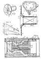
- Fig. 1 shows a perspective view of a device according to the invention,
- Fig. 2 shows a schematic section of a bladder with urethra and device implanted therein,
- Fig. 3 shows an axial section of the device in fig. 1, wherein the valve system in the housing is illustrated schematically,
- Fig. 4 shows an axial section of the valve system applicable in the device from fig. 1 and 2, on a larger scale,
- Fig. 5 shows a diagram wherein the opening force is plotted in relation to the opening path of the valve system.
- In the figures the housing of the device is indicated with the number 1, which housing, as will be apparent from fig. 2, is suitable for implantation at the junction between the
bladder 2 and the urethra 3. For this purpose said housing is formed with a cylindrical part 4 which is situated in the urethra 3 and a funnel-shaped part 5 which opens into the bladder. A valve system 6, which is further explained below, is accomodated in said cylindrical part 4. - The housing 1 consists of a rigid body of titanium alloy 7 which is coated on the exterior with a layer of tissue compatible material 8 known under the trade name "Proplast". This material bonds well to the tissue and because of its structure is suitable for making possible the growth of tissue thereon. For the attachment that is carried out once during the first operation, the layer 8 is extended on the funnel side past the inner titanium wall 7 to a bonding flange 9 which is provided with
holes 10 for feeding through cord-form, stitching material suitable for this purpose. - On the other end of housing 1 said titanium inner wall 7 is thickened at 11, such that its outer surface runs flush with the outer surface of layer 8. On the one hand displacement between the two parts 7 and 8 is hereby prevented, while on the other hand tissue growth at this location is prevented, in order to enable the introduction of valve system 6 into this cylindrical end part.
- An embodiment of the valve system 6 is further shown on a larger scale in fig. 4.
- Said valve system consists substantially of a
cylindrical part 12, the outer circumference of which is accomodated slidably fitting in cylindrical part 4 of housing 1. Saidcylindrical part 12 is formed on the inside with a bore 13, in the bottom of which a ring-shapedmagnetic body 14 is attached. Saidcylindrical part 12 is likewise provided at its other end with a bore 15, wherein a valve body is accomodated. By means of a screw thread or the like aring 18 containing thevalve seat 17 is screwed onto said other end. - On the left hand side in fig. 4 the
valve 16 is a truncated cone shape, the cone mantle thereof co-operating with a conical face ofvalve seat 17, such that a liquid tight closure is assured. - The
valve 16 is screwed onto a valve carrier 19 whereby a ring 20 having radially projecting plates 21 is clamped firmly between said valve carrier 19 and thevalve body 16. Said plates 21 have a circumscribed circle which corresponds with the circular inner wall of bore 15, so that said plates 21 enable axial sliding ofvalve body 16 in said bore 15 away from and towardsvalve seat 17. - At a distance from
valve body 16 the carrier 19 is formed with anannular magnet 22 which cooperates withmagnet ring 14 incylindrical part 12. Said magnet rings each have conical end faces 23, 24 which run parallel to one another. - The carrier 19 is formed with an axially directed threaded hole 25, wherein a threaded
body 26 is adjustable in axial sense by rotation. Rotation is carried out by way of aslot 27 arranged in the end face of said threadedbody 26, in which slot a screwdriver can be placed. The location of threaded hole 25 in relation topermanent magnet rings body 26 can be fed through the rings more or less whereby the path of lines of force and therefor the force of attraction of said magnet-rings in relation to one another can be varied. - Finally the carrier 19 features a bush-shaped end 28 on the outside of which ribs 29 are arranged, the circumscribed circle of which corresponds with the inner surface of the bore 13. In this way accurate centric displacement of said carrier 19 in axial sense is assured. The plates 21 as well as the ribs 29 can moreover feature a blade form, so that with liquid transport in fig. 4 from left to right through the cylindrical part 12 a rotation of the
valve 16 and valve carrier 19 is brought about. - The attachment of valve system 6 in cylindrical part 4 of housing 1 can take place by means of magnets. To this end the valve casing close to the funnel-shaped end is provided with a crown of
permanent magnets 30, against which a ring ofmagnetizable material 31 attached to thepart 18 can be pressed. For fitting or removal of the valve system 6, the latter only has to be fed axially into the cylindrical part 4 of housing 1 until thering 31 makes contact with the crown ofmagnets 30. Conversely the valve system 6 can be removed by being pulled loose. A safety precaution is moreover hereby achieved, if the passage of liquid is prevented whenvalve body 16 jams. At a sufficiently high pressure in the bladder said valve system 6 will shoot loose whereby the passage through housing 1 is left clear. - The operation of valve system 6 is as follows:
- In fig. 4
valve body 16 is drawn in the opened position andmagnet rings valve seat 17, whereby the passage is closed off. - At a sufficiently high pressure said
valve body 16 is moved to the right by the liquid which can flow away via bore 15 or 13. - The opening pressure is determined here by the extent to which the threaded
body 26 is screwed into the carrier 19. As this body is carried more between therings body 26 is screwed outwards, the magnetic force of attraction is then lowered. - Secondly the opening force can be determined by the remaining clearance between
magnet rings valve 16. This is determined by the difference in distance between the conical end face of valve body andmagnet ring 22 less the distance betweenvalve seat 17 andmagnet ring 14. This distance is adjustable, among other ways, by changing the thickness of the ring 20 between valve body and valve carrier. By choosing a greater gap between themagnet rings - The closing force of the magnetic rings can also be determined by limiting the movement directed in fig. 4 towards the right of
valve body 16 and carrier 19, which movement is limited by the plate-form blades 21 of ring 20 which stop against the converging part of the bore 15. By chamfering said blades more or less at A, the maximum gap size between magnet rings 14, 22 and thereby the closing force, can be accurately determined. - Fig. 5 shows the result of this graphically. The force of attraction between magnet rings 14, 22 is indicated on the vertical axis while the size of the gap between them is plotted on the horizontal axis.
- The line M1 shows a cure for a situation where for example the
core 26 is screwed as far as possible between the rings. Line M2 shows a curve whereby the threadedbody 26 is unscrewed as far as possible. It will be evident that any line between these two can be obtained by determining the position of threadedbody 26. Assuming that there is a minimum determined gap (Sm) present between the rings, each curve determines its own force Fo. The closing force Fs is determined by the maximum gap Smax and the corresponding curve. - It will be apparent that the curve itself can still be altered by respectively the choice of material for the magnet rings and the dimensioning thereof. The curve is likewise determined by the vertical angle of the conical mantle of the
respective rings - The invention is not limited to the embodiment described above. Another closing means for the
valve 16 can be applied instead of magnets, for example springs or the like. Within the framework of the magnetic embodiment it will be evident that the valve body and the position of the magnets relative to one another can also be different.
Claims (10)
Priority Applications (1)
| Application Number | Priority Date | Filing Date | Title |
|---|---|---|---|
| AT85201706T ATE53934T1 (en) | 1984-10-17 | 1985-10-17 | IMPLANTABLE OCCLUSION DEVICE. |
Applications Claiming Priority (2)
| Application Number | Priority Date | Filing Date | Title |
|---|---|---|---|
| NL8403174 | 1984-10-17 | ||
| NL8403174A NL8403174A (en) | 1984-10-17 | 1984-10-17 | IMPLANTABLE SEALING DEVICE. |
Publications (2)
| Publication Number | Publication Date |
|---|---|
| EP0182409A1 EP0182409A1 (en) | 1986-05-28 |
| EP0182409B1 true EP0182409B1 (en) | 1990-06-20 |
Family
ID=19844631
Family Applications (1)
| Application Number | Title | Priority Date | Filing Date |
|---|---|---|---|
| EP85201706A Expired - Lifetime EP0182409B1 (en) | 1984-10-17 | 1985-10-17 | Implantable shut-off device |
Country Status (5)
| Country | Link |
|---|---|
| US (1) | US4679546A (en) |
| EP (1) | EP0182409B1 (en) |
| AT (1) | ATE53934T1 (en) |
| DE (1) | DE3578308D1 (en) |
| NL (1) | NL8403174A (en) |
Families Citing this family (58)
| Publication number | Priority date | Publication date | Assignee | Title |
|---|---|---|---|---|
| US4736747A (en) * | 1986-04-11 | 1988-04-12 | Minnesota Mining And Manufacturing Company | Adjustable magnetic supercutaneous device and transcutaneous coupling apparatus |
| US5108430A (en) * | 1987-02-20 | 1992-04-28 | Biagio Ravo | Implantable reservoir adapted to receive and store structural devices therein |
| US5010882A (en) * | 1989-11-13 | 1991-04-30 | American Medical Systems, Inc. | Implantable penile prosthesis |
| US5140999A (en) * | 1991-09-30 | 1992-08-25 | Primed International Corp. | Urinary incontinence valve device |
| DE69432903T2 (en) * | 1993-12-23 | 2004-05-19 | Feelsure Health Corp., Winnetka | NON-SURGICAL INTRAURETHRAL BUBBLE CONTROL DEVICE |
| US5512032A (en) | 1993-12-23 | 1996-04-30 | Hk Medical Technologies, Inc. | Nonsurgical intraurethral bladder control device |
| SE504276C2 (en) * | 1993-12-30 | 1996-12-23 | Siko Medical Ab | Valve intended to be placed in the urethra |
| US5762599A (en) * | 1994-05-02 | 1998-06-09 | Influence Medical Technologies, Ltd. | Magnetically-coupled implantable medical devices |
| GB9425578D0 (en) * | 1994-12-19 | 1995-02-15 | Connolly John G | redial treatment of urinary incontinence |
| US6540665B1 (en) * | 1994-06-16 | 2003-04-01 | John G. Connolly | Urinary incontinence device |
| US5624374A (en) * | 1994-11-03 | 1997-04-29 | Von Iderstein; Irwin F. | Involuntary urine control apparatus, system and method |
| TW354259B (en) * | 1994-11-03 | 1999-03-11 | Uroscientific Inc | Urethra control system the invention relates to an involunary urine control system |
| DE69532086T2 (en) * | 1994-12-09 | 2004-11-25 | Medtronic Xomed, Inc., North Jacksonville | VALVE ARRANGEMENT TO REDUCE SYNOVIAL LIQUID PRESSURE |
| US5772694A (en) * | 1995-05-16 | 1998-06-30 | Medical Carbon Research Institute L.L.C. | Prosthetic heart valve with improved blood flow |
| US5618257A (en) | 1995-08-16 | 1997-04-08 | Hk Medical Technologies Incorporated | Bladder control insertion apparatus and method |
| US5701916A (en) | 1995-08-16 | 1997-12-30 | Hk Medical Technologies Incorporated | Intraurethral bladder control device with retainer apparatus |
| US5906575A (en) | 1996-04-25 | 1999-05-25 | Rochester Medical Corporation | Urethral urine retention device |
| US5751606A (en) * | 1996-05-03 | 1998-05-12 | Hk Medical Technologies Incorporated | Automatic valve test apparatus |
| US5782916A (en) | 1996-08-13 | 1998-07-21 | Galt Laboratories, Inc. | Device for maintaining urinary continence |
| US5964732A (en) | 1997-02-07 | 1999-10-12 | Abbeymoor Medical, Inc. | Urethral apparatus with position indicator and methods of use thereof |
| US5989179A (en) * | 1997-07-07 | 1999-11-23 | Hk Medical Technologies Incorporated | Bladder control device housing and method |
| US5893826A (en) * | 1997-08-14 | 1999-04-13 | Salama; Fouad A. | Artificial sphincter urinary control system |
| US5971967A (en) | 1997-08-19 | 1999-10-26 | Abbeymoor Medical, Inc. | Urethral device with anchoring system |
| US5996585A (en) | 1997-08-21 | 1999-12-07 | Hk Medical Technologies Incorporated | Nonsurgical intraurethral bladder control device retainer |
| US5871016A (en) * | 1997-10-08 | 1999-02-16 | Hk Medical Technologies Incorporated | Bladder control device retainer and method |
| US6352543B1 (en) | 2000-04-29 | 2002-03-05 | Ventrica, Inc. | Methods for forming anastomoses using magnetic force |
| US6464999B1 (en) | 1998-06-17 | 2002-10-15 | Galt Incorporated | Bioadhesive medical devices |
| AU1709600A (en) * | 1998-10-28 | 2000-05-15 | Srs Medical Systems, Inc. | Flow-around valve with contoured fixation balloon and channel blocking means |
| US6183413B1 (en) * | 1998-12-09 | 2001-02-06 | Hk Medical Technologies Incorporated | Valve for bladder control device |
| ES2150881B1 (en) * | 1999-02-11 | 2002-02-16 | Univ Madrid Complutense | EXTERNAL MAGNETIC OPERATING VALVE FOR AN INTRAURETRAL ARTIFICIAL URINARY SPINTER. |
| GB2356915A (en) * | 1999-11-23 | 2001-06-06 | Envirotech Products Ltd | Magnetic venting valve with roll-over mechanism |
| US10327880B2 (en) | 2000-04-14 | 2019-06-25 | Attenuex Technologies, Inc. | Attenuation device for use in an anatomical structure |
| US7232449B2 (en) | 2000-04-29 | 2007-06-19 | Medtronic, Inc. | Components, systems and methods for forming anastomoses using magnetism or other coupling means |
| US7241300B2 (en) * | 2000-04-29 | 2007-07-10 | Medtronic, Inc, | Components, systems and methods for forming anastomoses using magnetism or other coupling means |
| US8518062B2 (en) | 2000-04-29 | 2013-08-27 | Medtronic, Inc. | Devices and methods for forming magnetic anastomoses between vessels |
| US20050080439A1 (en) * | 2000-04-29 | 2005-04-14 | Carson Dean F. | Devices and methods for forming magnetic anastomoses and ports in vessels |
| US6802847B1 (en) | 2000-04-29 | 2004-10-12 | Ventrica, Inc. | Devices and methods for forming magnetic anastomoses and ports in vessels |
| US7909837B2 (en) | 2000-12-13 | 2011-03-22 | Medtronic, Inc. | Methods, devices and systems for forming magnetic anastomoses |
| US20020143347A1 (en) * | 2000-12-13 | 2002-10-03 | Ventrica, Inc. | Extravascular anastomotic components and methods for forming vascular anastomoses |
| EP1363567B1 (en) * | 2001-01-29 | 2009-09-16 | Eutech Medical AB | Valve assembly |
| US20050165344A1 (en) * | 2003-11-26 | 2005-07-28 | Dobak John D.Iii | Method and apparatus for treating heart failure |
| US7666133B2 (en) * | 2004-12-06 | 2010-02-23 | Sam Drager | Apparatus and method for correcting urinary incontinence |
| US8864730B2 (en) | 2005-04-12 | 2014-10-21 | Rochester Medical Corporation | Silicone rubber male external catheter with absorbent and adhesive |
| DE102005046333B3 (en) * | 2005-09-27 | 2006-10-19 | Viega Gmbh & Co. Kg | Press-tool for connecting pipes has jaws whose rear ends can overlap as they are opened, allowing them to be used on large diameter pipes |
| US20100106255A1 (en) * | 2008-10-24 | 2010-04-29 | Dubin Marc G | Self-expanding frontal sinus stent and insertion tool |
| EP2367503A1 (en) | 2008-11-25 | 2011-09-28 | AttenueX Technologies, Inc. | Implant with high vapor pressure medium |
| NL1036388C2 (en) * | 2009-01-07 | 2010-07-08 | Applied Medical Developments B V | DEVICE SUITABLE FOR IMPLANTATION AT A DESIRED POSITION IN A LUMEN OF A HEAT-BLOODED LIFE AND A HOLDER SUITABLE FOR SUCH INVENTION. |
| US8992410B2 (en) | 2010-11-03 | 2015-03-31 | Vysera Biomedical Limited | Urological device |
| PT2635338T (en) * | 2010-11-03 | 2019-01-11 | Coloplast As | A urological device |
| US9707375B2 (en) | 2011-03-14 | 2017-07-18 | Rochester Medical Corporation, a subsidiary of C. R. Bard, Inc. | Catheter grip and method |
| US8894563B2 (en) | 2012-08-10 | 2014-11-25 | Attenuex Technologies, Inc. | Methods and systems for performing a medical procedure |
| US9872969B2 (en) | 2012-11-20 | 2018-01-23 | Rochester Medical Corporation, a subsidiary of C.R. Bard, Inc. | Catheter in bag without additional packaging |
| US10092728B2 (en) | 2012-11-20 | 2018-10-09 | Rochester Medical Corporation, a subsidiary of C.R. Bard, Inc. | Sheath for securing urinary catheter |
| EP3049019A1 (en) | 2013-09-25 | 2016-08-03 | Medtronic, Inc. | Implantable urinary tract valve |
| WO2016033234A1 (en) | 2014-08-26 | 2016-03-03 | C.R. Bard, Inc | Urinary catheter |
| CN104983491B (en) * | 2015-06-24 | 2017-10-13 | 徐传河 | A kind of self control urination formula prostate bracket |
| CA3070865A1 (en) | 2017-09-19 | 2019-03-28 | C.R. Bard, Inc. | Urinary catheter bridging device, systems and methods thereof |
| US20200254226A1 (en) | 2019-02-07 | 2020-08-13 | Solace Therapeutics, Inc. | Pressure attenuation device |
Family Cites Families (9)
| Publication number | Priority date | Publication date | Assignee | Title |
|---|---|---|---|---|
| DE930186C (en) * | 1952-07-24 | 1955-07-11 | Walter Jordan | Bottom valve for liquid suction lines |
| US3181895A (en) * | 1960-09-27 | 1965-05-04 | Crawford Fitting Co | Quick-connect magnetic couplings |
| US3503400A (en) * | 1967-07-12 | 1970-03-31 | Sven M Osthagen | Urethral valve |
| DE1911649A1 (en) * | 1969-03-07 | 1970-09-24 | Siegfried Klusch | Overflow valve preferably for blood circulation as a safety and control valve with externally adjustable magnetic closing forces |
| US3768102A (en) * | 1972-02-03 | 1973-10-30 | Univ Utah | Implantable artificial urethral valve |
| US3812841A (en) * | 1972-08-21 | 1974-05-28 | L Isaacson | Urethra magnetic valve structure |
| US3997923A (en) * | 1975-04-28 | 1976-12-21 | St. Jude Medical, Inc. | Heart valve prosthesis and suturing assembly and method of implanting a heart valve prosthesis in a heart |
| DE2624418A1 (en) * | 1976-05-31 | 1977-12-22 | Hennig Gerhard | Prosthetic urethral valve for incontinent females - is held closed by magnetic force and opened by pulling a cord |
| US4574833A (en) * | 1984-06-06 | 1986-03-11 | Custer Craig S | Excess flow control device |
-
1984
- 1984-10-17 NL NL8403174A patent/NL8403174A/en not_active Application Discontinuation
-
1985
- 1985-10-16 US US06/788,155 patent/US4679546A/en not_active Expired - Lifetime
- 1985-10-17 AT AT85201706T patent/ATE53934T1/en not_active IP Right Cessation
- 1985-10-17 EP EP85201706A patent/EP0182409B1/en not_active Expired - Lifetime
- 1985-10-17 DE DE8585201706T patent/DE3578308D1/en not_active Expired - Fee Related
Also Published As
| Publication number | Publication date |
|---|---|
| DE3578308D1 (en) | 1990-07-26 |
| ATE53934T1 (en) | 1990-07-15 |
| US4679546A (en) | 1987-07-14 |
| EP0182409A1 (en) | 1986-05-28 |
| NL8403174A (en) | 1986-05-16 |
Similar Documents
| Publication | Publication Date | Title |
|---|---|---|
| EP0182409B1 (en) | Implantable shut-off device | |
| US4705516A (en) | Setting for a cardiac valve | |
| EP1350483B1 (en) | Nonsurgical intraurethral bladder control device | |
| US4911716A (en) | Surgical implant for a voice prosthesis | |
| EP1634552B1 (en) | Cap and activation tool | |
| US4790843A (en) | Prosthetic heart valve assembly | |
| US5004454A (en) | Auxiliary intra-urethral magnetic valve for persons suffering from urinary incontinence | |
| US4846841A (en) | Femoral Prosthesis | |
| EP0229729B1 (en) | Implantable treatment reservoir | |
| US3370305A (en) | Heart valve with magnetic hinge means | |
| US3813699A (en) | Prosthetic hip joint | |
| US4792337A (en) | Acetabulum part for a total hip prosthesis | |
| JP2002520087A (en) | Intraurethral magnetic valve | |
| JPH02501042A (en) | Vascular prosthetic valve | |
| US5098397A (en) | Percutaneous access device | |
| EP3967273A1 (en) | Artificial valve for implantation | |
| US5139508A (en) | Surgical tool | |
| US4485609A (en) | Torque limited cap applicating head | |
| US20020095210A1 (en) | Heart pump graft connector and system | |
| CA2019573A1 (en) | Acetabular cup assembly | |
| GB2119904A (en) | Implantable magnetically-actuated valve | |
| KR20030051683A (en) | Body fluid flow control method and device | |
| GB1576594A (en) | Blood access device | |
| EP0302076B1 (en) | Implant passageway | |
| EP0139356A1 (en) | Acetabular cup prosthesis |
Legal Events
| Date | Code | Title | Description |
|---|---|---|---|
| PUAI | Public reference made under article 153(3) epc to a published international application that has entered the european phase |
Free format text: ORIGINAL CODE: 0009012 |
|
| AK | Designated contracting states |
Kind code of ref document: A1 Designated state(s): AT BE CH DE FR GB IT LI LU NL SE |
|
| 17P | Request for examination filed |
Effective date: 19861127 |
|
| 17Q | First examination report despatched |
Effective date: 19880321 |
|
| RAP3 | Party data changed (applicant data changed or rights of an application transferred) |
Owner name: APPLIED MEDICAL TECHNICS B.V. |
|
| GRAA | (expected) grant |
Free format text: ORIGINAL CODE: 0009210 |
|
| ITF | It: translation for a ep patent filed |
Owner name: STUDIO INGG. FISCHETTI & WEBER |
|
| AK | Designated contracting states |
Kind code of ref document: B1 Designated state(s): AT BE CH DE FR GB IT LI LU NL SE |
|
| REF | Corresponds to: |
Ref document number: 53934 Country of ref document: AT Date of ref document: 19900715 Kind code of ref document: T |
|
| ET | Fr: translation filed | ||
| REF | Corresponds to: |
Ref document number: 3578308 Country of ref document: DE Date of ref document: 19900726 |
|
| PLBE | No opposition filed within time limit |
Free format text: ORIGINAL CODE: 0009261 |
|
| STAA | Information on the status of an ep patent application or granted ep patent |
Free format text: STATUS: NO OPPOSITION FILED WITHIN TIME LIMIT |
|
| 26N | No opposition filed | ||
| ITTA | It: last paid annual fee | ||
| EPTA | Lu: last paid annual fee | ||
| EAL | Se: european patent in force in sweden |
Ref document number: 85201706.0 |
|
| PGFP | Annual fee paid to national office [announced via postgrant information from national office to epo] |
Ref country code: LU Payment date: 20010329 Year of fee payment: 16 |
|
| PGFP | Annual fee paid to national office [announced via postgrant information from national office to epo] |
Ref country code: AT Payment date: 20010404 Year of fee payment: 16 |
|
| REG | Reference to a national code |
Ref country code: GB Ref legal event code: IF02 |
|
| PGFP | Annual fee paid to national office [announced via postgrant information from national office to epo] |
Ref country code: GB Payment date: 20020402 Year of fee payment: 17 |
|
| PGFP | Annual fee paid to national office [announced via postgrant information from national office to epo] |
Ref country code: SE Payment date: 20020426 Year of fee payment: 17 Ref country code: FR Payment date: 20020426 Year of fee payment: 17 Ref country code: CH Payment date: 20020426 Year of fee payment: 17 Ref country code: BE Payment date: 20020426 Year of fee payment: 17 |
|
| PGFP | Annual fee paid to national office [announced via postgrant information from national office to epo] |
Ref country code: NL Payment date: 20020430 Year of fee payment: 17 Ref country code: DE Payment date: 20020430 Year of fee payment: 17 |
|
| PG25 | Lapsed in a contracting state [announced via postgrant information from national office to epo] |
Ref country code: LU Free format text: LAPSE BECAUSE OF NON-PAYMENT OF DUE FEES Effective date: 20021017 Ref country code: GB Free format text: LAPSE BECAUSE OF NON-PAYMENT OF DUE FEES Effective date: 20021017 Ref country code: AT Free format text: LAPSE BECAUSE OF NON-PAYMENT OF DUE FEES Effective date: 20021017 |
|
| PG25 | Lapsed in a contracting state [announced via postgrant information from national office to epo] |
Ref country code: SE Free format text: LAPSE BECAUSE OF NON-PAYMENT OF DUE FEES Effective date: 20021018 |
|
| PG25 | Lapsed in a contracting state [announced via postgrant information from national office to epo] |
Ref country code: LI Free format text: LAPSE BECAUSE OF NON-PAYMENT OF DUE FEES Effective date: 20021031 Ref country code: CH Free format text: LAPSE BECAUSE OF NON-PAYMENT OF DUE FEES Effective date: 20021031 Ref country code: BE Free format text: LAPSE BECAUSE OF NON-PAYMENT OF DUE FEES Effective date: 20021031 |
|
| BERE | Be: lapsed |
Owner name: *APPLIED MEDICAL TECHNICS B.V. Effective date: 20021031 |
|
| PG25 | Lapsed in a contracting state [announced via postgrant information from national office to epo] |
Ref country code: NL Free format text: LAPSE BECAUSE OF NON-PAYMENT OF DUE FEES Effective date: 20030501 Ref country code: DE Free format text: LAPSE BECAUSE OF NON-PAYMENT OF DUE FEES Effective date: 20030501 |
|
| EUG | Se: european patent has lapsed | ||
| GBPC | Gb: european patent ceased through non-payment of renewal fee |
Effective date: 20021017 |
|
| REG | Reference to a national code |
Ref country code: CH Ref legal event code: PL |
|
| PG25 | Lapsed in a contracting state [announced via postgrant information from national office to epo] |
Ref country code: FR Free format text: LAPSE BECAUSE OF NON-PAYMENT OF DUE FEES Effective date: 20030630 |
|
| NLV4 | Nl: lapsed or anulled due to non-payment of the annual fee |
Effective date: 20030501 |
|
| REG | Reference to a national code |
Ref country code: FR Ref legal event code: ST |