EP0186471A2 - Knee prosthesis - Google Patents
Knee prosthesis Download PDFInfo
- Publication number
- EP0186471A2 EP0186471A2 EP85309340A EP85309340A EP0186471A2 EP 0186471 A2 EP0186471 A2 EP 0186471A2 EP 85309340 A EP85309340 A EP 85309340A EP 85309340 A EP85309340 A EP 85309340A EP 0186471 A2 EP0186471 A2 EP 0186471A2
- Authority
- EP
- European Patent Office
- Prior art keywords
- component
- bearing surface
- meniscal
- tibial
- femoral
- Prior art date
- Legal status (The legal status is an assumption and is not a legal conclusion. Google has not performed a legal analysis and makes no representation as to the accuracy of the status listed.)
- Granted
Links
Images


Classifications
-
- A—HUMAN NECESSITIES
- A61—MEDICAL OR VETERINARY SCIENCE; HYGIENE
- A61F—FILTERS IMPLANTABLE INTO BLOOD VESSELS; PROSTHESES; DEVICES PROVIDING PATENCY TO, OR PREVENTING COLLAPSING OF, TUBULAR STRUCTURES OF THE BODY, e.g. STENTS; ORTHOPAEDIC, NURSING OR CONTRACEPTIVE DEVICES; FOMENTATION; TREATMENT OR PROTECTION OF EYES OR EARS; BANDAGES, DRESSINGS OR ABSORBENT PADS; FIRST-AID KITS
- A61F2/00—Filters implantable into blood vessels; Prostheses, i.e. artificial substitutes or replacements for parts of the body; Appliances for connecting them with the body; Devices providing patency to, or preventing collapsing of, tubular structures of the body, e.g. stents
- A61F2/02—Prostheses implantable into the body
- A61F2/30—Joints
- A61F2/38—Joints for elbows or knees
- A61F2/3868—Joints for elbows or knees with sliding tibial bearing
-
- A—HUMAN NECESSITIES
- A61—MEDICAL OR VETERINARY SCIENCE; HYGIENE
- A61F—FILTERS IMPLANTABLE INTO BLOOD VESSELS; PROSTHESES; DEVICES PROVIDING PATENCY TO, OR PREVENTING COLLAPSING OF, TUBULAR STRUCTURES OF THE BODY, e.g. STENTS; ORTHOPAEDIC, NURSING OR CONTRACEPTIVE DEVICES; FOMENTATION; TREATMENT OR PROTECTION OF EYES OR EARS; BANDAGES, DRESSINGS OR ABSORBENT PADS; FIRST-AID KITS
- A61F2/00—Filters implantable into blood vessels; Prostheses, i.e. artificial substitutes or replacements for parts of the body; Appliances for connecting them with the body; Devices providing patency to, or preventing collapsing of, tubular structures of the body, e.g. stents
- A61F2/02—Prostheses implantable into the body
- A61F2/30—Joints
- A61F2/38—Joints for elbows or knees
- A61F2/3886—Joints for elbows or knees for stabilising knees against anterior or lateral dislocations
Definitions
- This invention relates to endo-prosthetic knee joint devices.
- a first aspect of the present invention relates to a knee prosthesis which is in three parts.
- the prosthesis comprises a femoral component for attachment to the femur, a tibial component for attachment to the tibia and a meniscal component to lie between the femoral and tibial components.
- the femoral component has a bearing surface which is tangentially curved about medio-lateral axes and the meniscal component has a bearing surface complementary to the femoral bearing surface.
- the tibial component has a concave curved surface and the meniscal component has a bearing surface complementary to the tibial component's bearing surface.
- the posterior surface of the meniscal component is curved to form a cam surface against which the bar moves.
- the prosthesis includes a bar which is of curved cross section.
- FIG. 7 shows the different shaped recesses which may be used for different knee problems.
- the recess is the same size as the peg 21 so that no subluxation at all would be possible. This would be necessary if the ligaments were severely damaged.
- the recess is a slot or a larger diameter hole then the subluxation is allowed but is limited. This is for lesser degrees of damage to the ligaments.
Abstract
Description
- This invention relates to endo-prosthetic knee joint devices.
- Knee prostheses may be of the "constrained" type or of the "non-constrained" type. The former type replaces the functions of the bearing surfaces and of the ligaments and may take the form of a hinge. The latter type makes use of some or all of the natural ligaments to control the mode of articulation and/or prevent the separation of the opposing bearing surfaces of the prosthesis. This invention is concerned with knee prostheses of the non-constrained type.
- A natural knee articulates both in flexion and rotation, the freedom to rotate increasing from zero at full extension to a maximum at full flexion. Flexion occurs about an axis which lies approximately perpendicular to tibia and parallel to the .frontal plane. This axis is, however, not fixed but moves backwards as flexion increases. Rotation occurs about the long axis of the tibia. The locus of the flexion axis and the limit to rotational freedom is determined by the shapes of the opposing bearing surfaces (condyles) of femur and tibia and also the inextensible length and positions of insertion of four ligaments which connect the femur to the tibia. These ligaments comprise two collateral ligaments and two cruciate ligaments. Non-congruity of opposing condyles allows a complex articulation. Load distribution is achieved by two intervening semi-lunar cartilages or meniscii. These meniscii approximately conform to the femoral surfaces and are free to move relative to the tibial condyles.
- A typical knee prosthesis includes a femoral component for attachment to the femur and tibial component for attachment to the tibia. Many knee prosthesis also include a meniscal component which is interposed between the femoral and tibial components. The femoral component and tibial component are usually attached to the bone using cement.
- A first aspect of the present invention relates to a knee prosthesis which is in three parts. The prosthesis comprises a femoral component for attachment to the femur, a tibial component for attachment to the tibia and a meniscal component to lie between the femoral and tibial components. The femoral component has a bearing surface which is tangentially curved about medio-lateral axes and the meniscal component has a bearing surface complementary to the femoral bearing surface. The tibial component has a concave curved surface and the meniscal component has a bearing surface complementary to the tibial component's bearing surface.
- The bearing surface of the femoral component comprises two condylar tracks joined by a patella bearing surface.
- Between the two condylar tracks is a gap which approximates to the intercondylar notch of the natural femur. The upper surface of the meniscal component has two co-axial cylindrical tracks complementary to the condylar bearing surface of the femoral component.
- With a knee prosthesis such as that described in British Published Patent Specification No 2120943 in which the bearing surfaces of the meniscal and tibial components are conical such that relative axial rotation is possbile between the tibial and meniscal components and subluxation of the meniscal component is allowed, it would be advantageous to provide means for restricting subluxation of the meniscal component, particularly in cases where the natural knee ligaments are damaged or weakened.
- A natural knee includes two pairs of ligaments which control movement of the knee. One pair, the cruciate ligaments, passes directly between the femur and the tibia in the central region of the joint, and thus in a joint replacement operation these crutiate ligaments may have to be removed. However, the other pair, known as the collateral ligaments, passes between the tibia and femur at the sides of the bones and can therefore be left in place.
- It has been found that the collateral ligaments give the knee joint a lot of its stability and prevent the bones from coming apart. Thus if the ligaments are healthy and working as they should, it has been found that it is preferable to allow the meniscal component to subluxate to a great degree. This is because the collateral ligaments will prevent any dislocating forces from dislodging the meniscal component from the tibial component, as shown in British Published Patent Specification No 2120943. However, if the collateral ligaments have been damaged or weakened and are not therefore constraining the knee properly, then a dislocating force on the knee could damage such a knee since the meniscal component would be free to completely "ride out" of the tibial component, or move to an unstable position.
- According to the first aspect of the present invention there is provided a knee prosthesis comprising a femoral component for attachment to a femur and having a convex bearing surface which is tangentially curved about medio-lateral axes, a tibial component for attachment to a tibia and having a concave bearing surface, and a meniscal component to lie between the femoral and tibial components, said meniscal component having an inferior convex bearing surface complementary to that of the tibial component and a superior concave bearing surface complementary to that of the femoral component, the inferior bearing surface of the meniscal component and the bearing surface of the tibial component both being conical such that relative axial rotation is possible between said tibial and meniscal components, the meniscal component including a recess in > the base of its inferior bearing surface and a control peg Deing provided at the bearing surface of the tibial component, the control peg fitting in the recess in the neniscal component to control the subluxation thereof.
- The control peg is preferably detachable from the tibial component, the tibial component having an alignment zole extending therethrough, the control peg fitting into said alignment hole in the tibial component.
- The advantage of this particular preferred feature is that when the knee prosthesis is being fitted, an alignment rod may be inserted through the tibial component while the peg is removed and then after the tibial component is fitted, the alignment rod is removed and the peg may be replaced.
- Such a tibial component has an alignment hole extending therethrough for the purpose of fitting the prosthesis as described above, and preferably a plastic sleeve is, at least in use, located between the control peg and the inside of the alignment hole to key the peg within the hole.
- Because the axis of rotation of the knee prosthesis needs to be located behind the axis of the alignment hole in the tibial component, preferably the control peg comprises two portions, an inferior portion for inserting into the alignment hole and a superior portion for inserting within the recess in the inferior bearing surface of the meniscal component, the longitudinal axes of said inferior and superior portions being laterally offset from each other, and the two portions being rigidly connected together by means of a collar which, in use, fits into a correspondingly shaped recess in the bearing surface of the tibial component, the alignment hole lying eccentrically within the recess in the tibial component.
- The control peg may control the relative movements of the tibial and meniscal components in a number of different ways.
- The meniscal component may be exactly the same size as :he control peg in the bearing surface of the tibial component so that subluxation is prevented and rotation only is allowed.
- Alternatively, the recess in the inferior bearing surface of the meniscal component comprises a slot which allows subluxation in one direction only.
- In still further alternative embodiments, the recess comprises a round hole of larger diameter than the control peg to allow limited subluxation in any direction, or alternatively the peg and recess are of non-round shape to provide a limited rotational freedom.
- The use of a control peg in this way to control subluxation means that posterior stabilisation may be utilised in the knee prosthesis.
- Preferably, this is provided by producing a knee prosthesis in which the femoral component has a bearing surface comprising a patella-bearing area and a pair of condylar tracks which are tangentially curved about medio-lateral axes, a space being defined between the condylar tracks, and in which the meniscal component lying between the femoral and tibial components has bearing surfaces complementary to said pair of condylar tracks of the femoral component and to the bearing surface of the tibial component, and in which a bar extends between the condylar tracks of the femoral component at the posterior portion of the tracks and a central projection is provided on the meniscal component such that the bar engages the rear of the centrally placed projection to cause the femoral component to roll to the back of the meniscal component.
- This means that the range of flexion of the prosthesis is increased.
- Preferably, the posterior surface of the meniscal component is curved to form a cam surface against which the bar moves.
- More preferably, the prosthesis includes a bar which is of curved cross section.
- The advantage of the bar formed on the femoral component is that it is not necessary to resect any additional bone from the intercondylar region of the femur to accommodate the femoral component. The normal resection required to fit the prosthesis is sufficient, and the intercondylar projection on the meniscal component simply fits into the space provided by the gap between the two condylar sections of the femcral component. The bar drives the meniscal component, and through this the tibial component, forward at high degrees of flexion so that the movement of the knee prosthesis simulates the function of the posterior cruciate ligament.
- A second aspect of the present invention relates to means for fixing the femoral component on the end of the femur without the use of bone cement.
- In surgery, it is preferable to be able to use as little cement as possible since the introduction of cement between the prosthesis and the bone introduces a further interface which increases the risk of infection. Whilst it is becoming possible to avoid the use of cement in the fixation of tibial components to the tibia, since they tend to be inserted into the end of the tibia, and any forces on the component tends to force the component into the bone, the case is different with the femoral component which tends to be placed over the end of the femur. Also the knee exerts shearing and tipping forces on the femoral component with respect to the femur.
- According to a second aspect of the present invention there is provided a femoral component for a knee prosthesis, said femoral component having an inner bone . contacting surface and an outer bearing surface, in which the component includes on its inner bone contacting side a serrated surface which serves to key the femoral component to the bone without the use of cement, the angle of the serrations being such that the femoral component will push easily onto the femur but will resist any forces tending to pull the femoral component away from the femur.
- The serrated surface may be integral with the femoral component. In this case, since the femoral component is often metallic, when the component is placed over the end of the resected femur, the bone is deformed, and then returns to its normal position which helps to prevent distraction of the component.
- The elasticity of the bone causes recovery after passage of the serrations to engage the undercut of the trailing edge. The serrations are oriented such that they offer the least resistance to insertion and maximum resistance to distraction.
- For long term fixation, tissue ingrowth into bone features on the implant surfaces required, usually combined with a wedging action to produce sufficient stability to maintain the prosthesis bone apposition during the healing process. The wedging action is produced by producing a femoral component and resecting the femur into complementary wedge shapes. This means that as the femoral component is pushed onto the femur it is tightened into position.
- In an alternative embodiment, the serrated surface may be provided by at least one upwardly extending protrusion, said protrusion having a base member for locating within a correspondingly shaped slot in the femoral component, and an upper member extending from said base member and including a plurality of conical structures connected together in such a manner as to allow compression of said upper member when the femoral component is being pushed onto the femur, and extension of said upper member should any forces be applied tending to pull the femoral component away from the femur.
- Examples of several knee prostheses in accordance with aspects of the invention will now be described, by way of example only, with reference to the accompanying drawings in which:-
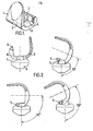
- Figure 1 is a perspective view of a femoral component in accordance with the first aspect of the invention;
- Figure 2 is a schematic view showing the flexion of the knee of Figure 1;
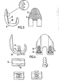
- Figure 3 is a schematic view of a femoral component in accordance with the second aspect of the invention;
- Figure 4 is a schematic view of a second example of a femoral component in accordance with the second aspect of the invention;
- Figure 5 is an exploded perspective view of a tibial component in accordance with the first aspect of the invention;
- Figure 6 is a perspective view of the tibial component shown in Figure 5;
- Figure 7 is a schematic view of examples of recesses in the meniscal component;
- Figure 8 is a schematic view of further examples of pegs for fitting in the tibial component of Figure 5; and,
- Figure 9 is a schematic view showing the asymmetric stability provided by an eccentric post, or recess.
- An example of knee prosthesis in accordance with the first aspect of the present invention includes a
femoral component 1 as shown in Figures 1 and 2. The femoral component includes a bearing surface comprising a patella bearing area 2 and two condylar tracks 3. The condylar tracks are tangentially curved about medio-lateral axes. A gap 4 is defined between the two tracks 3. At the posterior end of the condylar tracks 3 is abar 5 which extends between the tracks. - The prosthesis also includes a meniscal component 6 including two condylar tracks complementary to the condylar bearing surfaces 3 of the femoral component between which is centrally disposed meniscal projection 7. The meniscal projection fits between the intercondylar space on the femoral component. The posterior corner of the projection 8 is curved. When the knee is in full extension the projection is centrally disposed in the femoral component. As the knee is flexed the
femoral component 1 slides forward with respect to the meniscal component 6 untilbar 5 engages the rear of projection 7. - The bar engaging the projection 7 prevents further forward sliding of the femoral component and therefore causes the femoral component to roll backwards on the meniscal component during further flexion. The resultant backwards displacement of the axis of flexion increases the range of flexion that can be achieved without tissue entrapment or bone impingement such that a flexion in the region of 150° may be achieved.
- In an example of a knee prosthesis in accordance with the second aspect of the invention a
femoral component 9 includes on itsinner surface 10serrations 11 which project inwardly. Theserrations 11 are rigid, since they are integral with thefemoral component 9 and are therefore made of metal. The elasticity of the bone allows it to deform, as thefemoral component 9 is inserted over the resected femur, and subsequently relax so that distraction of thecomponent 9 is prevented. - A second example of a
femoral component 12 in accordance with the second aspect of the invention makes use of twomembers 13 each comprising a stack of conical flanges. Theflanges 14 may be made of a flexible plastics material which deform under insertion but which help prevent removal of the component when themembers 13 are in place. Each condylar track offemoral component 9 includes agroove 15 which includes aslot 16 cut from the side of the component. At the base of eachmember 13 is a flange which has a width such that it can be placed within the groove but a length which is wider than the groove. Thus the peg is slid into the groove and rotated until the flange 17 engages in theslot 16 to prevent thepeg 13 being removed from the femoral component. Theconical projections 14 help key thefemoral component 12 into position on the femur. - Examples of prosthesis in accordance with the first aspect of the present invention are shown in Figures 5 to 9.
- If a
tibial component 18 is to be used in many different types of knee operation, abore 19 is included at the base of itsconical bearing surface 20. If thetibial component 18 is to be used in a joint where either of the collateral ligaments are damaged apeg 21 is fixed into place usingplastic bush 22. - - Figure 7 shows the different shaped recesses which may be used for different knee problems. In 7A the recess is the same size as the
peg 21 so that no subluxation at all would be possible. This would be necessary if the ligaments were severely damaged. - If the recess is a slot or a larger diameter hole then the subluxation is allowed but is limited. This is for lesser degrees of damage to the ligaments.
- In some cases it may be necessary to prevent or reduce relative rotation of the meniscal component and the tibial component. This is achieved by using non-round pegs 23.
- Figure 9 illustrates how the direction of subluxation. may be controlled by changing the position of the
peg 22 with respect to alarger diameter hole 24.
Claims (14)
Applications Claiming Priority (2)
| Application Number | Priority Date | Filing Date | Title |
|---|---|---|---|
| GB848432267A GB8432267D0 (en) | 1984-12-20 | 1984-12-20 | Knee prosthesis |
| GB8432267 | 1984-12-20 |
Publications (3)
| Publication Number | Publication Date |
|---|---|
| EP0186471A2 true EP0186471A2 (en) | 1986-07-02 |
| EP0186471A3 EP0186471A3 (en) | 1987-05-20 |
| EP0186471B1 EP0186471B1 (en) | 1991-07-31 |
Family
ID=10571530
Family Applications (1)
| Application Number | Title | Priority Date | Filing Date |
|---|---|---|---|
| EP85309340A Expired - Lifetime EP0186471B1 (en) | 1984-12-20 | 1985-12-20 | Knee prosthesis |
Country Status (10)
| Country | Link |
|---|---|
| US (1) | US4950297A (en) |
| EP (1) | EP0186471B1 (en) |
| JP (1) | JPH0829151B2 (en) |
| AU (1) | AU591085B2 (en) |
| CA (1) | CA1291847C (en) |
| DE (1) | DE3583664D1 (en) |
| ES (1) | ES8705216A1 (en) |
| GB (1) | GB8432267D0 (en) |
| IE (1) | IE58925B1 (en) |
| NO (1) | NO167122C (en) |
Cited By (38)
| Publication number | Priority date | Publication date | Assignee | Title |
|---|---|---|---|---|
| GB2219942A (en) * | 1988-06-22 | 1989-12-28 | John Polyzoides | Knee prosthesis |
| FR2663536A1 (en) * | 1990-06-22 | 1991-12-27 | Implants Instr Ch Fab | Total knee prosthesis of the sliding type |
| EP0510178A1 (en) * | 1990-11-14 | 1992-10-28 | Arch Development Corporation | Improved floating bearing prosthetic knee |
| EP0519873A2 (en) * | 1991-06-17 | 1992-12-23 | André Bähler | Joint prosthesis, particularly for the knee |
| EP0529408A1 (en) * | 1991-08-24 | 1993-03-03 | Aesculap Ag | Knee endoprosthesis |
| EP0546726A1 (en) * | 1991-11-28 | 1993-06-16 | Biomet Limited | Prosthetic knee joint |
| FR2685632A1 (en) * | 1991-12-31 | 1993-07-02 | Procom Sa | Prosthetic assembly for producing a knee prosthesis |
| EP0568756A1 (en) * | 1992-04-23 | 1993-11-10 | Biomedical Engineering Trust I | Rotational and translational bearing combination in biological joint replacement |
| US5271747A (en) * | 1992-01-14 | 1993-12-21 | Sulzer Medizinaltechnik Ag | Meniscus platform for an artificial knee joint |
| EP0577529A1 (en) * | 1992-06-23 | 1994-01-05 | Medinov Sa | Total sliding prosthesis for the knee |
| EP0589325A1 (en) * | 1992-09-24 | 1994-03-30 | Waldemar Link (GmbH & Co.) | Knee joint endoprosthesis for replacement of the tibial articular surfaces |
| EP0592750A1 (en) * | 1992-01-14 | 1994-04-20 | SULZER Medizinaltechnik AG | Meniscus platform for artificial knee joint |
| FR2702369A1 (en) * | 1993-03-10 | 1994-09-16 | Voydeville Gilles | Knee prosthesis |
| US5370700A (en) * | 1993-02-19 | 1994-12-06 | Sarkisian; James S. | Prosthetic knee joint |
| EP0627202A1 (en) * | 1993-04-05 | 1994-12-07 | Procom S.A. | Prosthetic assembly for forming a knee joint |
| EP0636353A1 (en) * | 1993-07-28 | 1995-02-01 | G. Cremascoli S.R.L. | Full knee prosthesis |
| EP0639356A1 (en) * | 1993-08-18 | 1995-02-22 | SULZER Medizinaltechnik AG | Process for shaping external anchoring surfaces for joint implants |
| BE1008201A3 (en) * | 1992-06-26 | 1996-02-13 | Cremascoli G Srl | Total knee prosthesis. |
| FR2735682A1 (en) * | 1995-06-21 | 1996-12-27 | Afriat Jacques | TOTAL KNEE JOINT PROSTHESIS |
| GB2304051A (en) * | 1995-08-09 | 1997-03-12 | Corin Medical Ltd | A Knee Prosthesis Having Interchangeable Meniscal Components |
| FR2756483A1 (en) * | 1996-12-02 | 1998-06-05 | Gerard Ysebaert | Knee joint prosthesis |
| WO1998025550A1 (en) * | 1996-12-09 | 1998-06-18 | Groupe Contrôle Dedienne Gcd S.A. | Complete knee joint prosthesis |
| WO1999013804A1 (en) * | 1997-09-17 | 1999-03-25 | Smith & Nephew, Inc. | Mobile bearing knee prosthesis |
| CH689539A5 (en) * | 1991-06-17 | 1999-06-15 | Andre Baehler | Knee joint prosthesis |
| DE19755776A1 (en) * | 1997-12-16 | 1999-07-01 | Chiropro Gmbh | Prosthesis part e.g. knee or hip joint with parallel grooves |
| WO2001097719A1 (en) | 2000-06-19 | 2001-12-27 | Mathys Medizinaltechnik Ag | Knee-joint endoprosthesis |
| EP1023881A3 (en) * | 1999-01-28 | 2002-06-05 | Depuy Orthopaedics, Inc. | Modular tibial insert for prosthesis system |
| US6428577B1 (en) | 1998-05-20 | 2002-08-06 | Smith & Nephew, Inc. | Mobile bearing knee prosthesis |
| US6660039B1 (en) | 1998-05-20 | 2003-12-09 | Smith & Nephew, Inc. | Mobile bearing knee prosthesis |
| US7008454B2 (en) | 2003-04-09 | 2006-03-07 | Biomedical Engineering Trust I | Prosthetic knee with removable stop pin for limiting anterior sliding movement of bearing |
| US7014660B2 (en) | 2002-04-10 | 2006-03-21 | Biomedical Engineering Trust I | Prosthetic knee with removable stop pin for limiting anterior sliding movement of bearing |
| FR2916136A1 (en) * | 2007-05-18 | 2008-11-21 | Patrick Hechard | Femoral-knee prosthesis part for long bone, has blade integrated by edges of cylindrical implantation surface, and penetrating in resected end of bone by translation of piece in direction parallel to cone distance |
| EP2046248A1 (en) * | 2006-07-18 | 2009-04-15 | Biomet Manufacturing Corp. | Method and apparatus for a knee implant |
| AU2006203781B2 (en) * | 2000-09-26 | 2010-09-16 | Smith & Nephew, Inc. | Mobile bearing knee prosthesis |
| WO2012113690A2 (en) | 2011-02-22 | 2012-08-30 | Jossi Holding Ag | Method for producing an implant comprising at least one region having a surface structure, implant produced according to the method and device for performing the method |
| US8308808B2 (en) | 2010-02-19 | 2012-11-13 | Biomet Manufacturing Corp. | Latent mobile bearing for prosthetic device |
| US9155626B2 (en) | 2012-09-10 | 2015-10-13 | Acumed Llc | Radial head prosthesis with floating articular member |
| US9763792B2 (en) | 2015-10-01 | 2017-09-19 | Acumed Llc | Radial head prosthesis with rotate-to-lock interface |
Families Citing this family (71)
| Publication number | Priority date | Publication date | Assignee | Title |
|---|---|---|---|---|
| US5147406A (en) * | 1991-04-22 | 1992-09-15 | Zimmer, Inc. | Femoral component for a knee joint prosthesis having a modular cam and stem |
| US5282868A (en) * | 1991-06-17 | 1994-02-01 | Andre Bahler | Prosthetic arrangement for a complex joint, especially knee joint |
| FR2684290B1 (en) * | 1991-11-29 | 1994-01-21 | Tornier Ets | KNEE PROSTHESIS. |
| US5290313A (en) * | 1992-11-23 | 1994-03-01 | Zimmer, Inc. | Offset prosthetic stem extension |
| US5413604A (en) * | 1992-12-24 | 1995-05-09 | Osteonics Corp. | Prosthetic knee implant for an anterior cruciate ligament deficient total knee replacement |
| EP0689406A1 (en) * | 1993-12-30 | 1996-01-03 | Bruno E. Dr. Gerber | Knee endoprosthesis |
| US5944756A (en) * | 1994-02-22 | 1999-08-31 | Johnson & Johnson Professional, Inc. | Modular prosthesis with offset attachment mechanism |
| US5549686A (en) * | 1994-06-06 | 1996-08-27 | Zimmer, Inc. | Knee prosthesis having a tapered cam |
| GB2290476B (en) * | 1995-06-02 | 1999-02-10 | Corin Medical Ltd | Knee prosthesis |
| US5871543A (en) * | 1996-02-23 | 1999-02-16 | Hofmann; Aaron A. | Tibial prosthesis with mobile bearing member |
| US5702465A (en) * | 1996-05-13 | 1997-12-30 | Sulzer Orthopedics Inc. | Patella prosthesis having rotational and translational freedom |
| US5879391A (en) * | 1996-09-30 | 1999-03-09 | Johnson & Johnson Professional, Inc. | Modular prosthesis |
| US5782920A (en) * | 1996-11-14 | 1998-07-21 | Johnson & Johnson Professional, Inc. | Offset coupling for joint prosthesis |
| FR2768613B1 (en) * | 1997-09-23 | 1999-12-17 | Tornier Sa | KNEE PROSTHESIS WITH ROTATABLE PLATFORM |
| US6053945A (en) * | 1997-09-25 | 2000-04-25 | Johnson & Johnson Professional, Inc. | Joint prosthesis having controlled rotation |
| US5951603A (en) * | 1997-09-25 | 1999-09-14 | Johnson & Johnson Professional, Inc. | Rotatable joint prosthesis with axial securement |
| US6010534A (en) * | 1997-09-25 | 2000-01-04 | Johnson & Johnson Professional, Inc. | Rotatable tibial prosthesis with keyed axial securement |
| DE59711302D1 (en) * | 1997-10-28 | 2004-03-18 | Ct Pulse Orthopedics Ltd | knee prosthesis |
| US5957979A (en) * | 1997-12-12 | 1999-09-28 | Bristol-Myers Squibb Company | Mobile bearing knee with metal on metal interface |
| US6123729A (en) | 1998-03-10 | 2000-09-26 | Bristol-Myers Squibb Company | Four compartment knee |
| EP0956836B1 (en) * | 1998-05-13 | 2004-07-28 | DePuy Products, Inc. | Tibial tray with adjustable keel |
| US6443991B1 (en) | 1998-09-21 | 2002-09-03 | Depuy Orthopaedics, Inc. | Posterior stabilized mobile bearing knee |
| US6162255A (en) * | 1998-10-15 | 2000-12-19 | Depuy Orthopaedics, Inc. | Stem offset mechanism for joint prosthesis |
| ES2144974B1 (en) * | 1998-11-19 | 2001-01-01 | Levante Ind Quirurgicas | KNEE PROTESIS WITH MOBILE CONGRUENT INSERT. |
| FR2788964B1 (en) * | 1999-01-28 | 2001-04-20 | Aesculap Sa | TIBIAL ANTI-TIPPING INSERT |
| US6165223A (en) * | 1999-03-01 | 2000-12-26 | Biomet, Inc. | Floating bearing knee joint prosthesis with a fixed tibial post |
| US6413279B1 (en) | 1999-03-01 | 2002-07-02 | Biomet, Inc. | Floating bearing knee joint prosthesis with a fixed tibial post |
| US6972039B2 (en) | 1999-03-01 | 2005-12-06 | Biomet, Inc. | Floating bearing knee joint prosthesis with a fixed tibial post |
| US6319283B1 (en) | 1999-07-02 | 2001-11-20 | Bristol-Myers Squibb Company | Tibial knee component with a mobile bearing |
| US6210445B1 (en) | 1999-10-26 | 2001-04-03 | Bristol-Myers Squibb Company | Tibial knee component with a mobile bearing |
| US6217618B1 (en) | 1999-10-26 | 2001-04-17 | Bristol-Myers Squibb Company | Tibial knee component with a mobile bearing |
| US6210444B1 (en) | 1999-10-26 | 2001-04-03 | Bristol-Myers Squibb Company | Tibial knee component with a mobile bearing |
| US6379388B1 (en) | 1999-12-08 | 2002-04-30 | Ortho Development Corporation | Tibial prosthesis locking system and method of repairing knee joint |
| EP1108403B1 (en) * | 1999-12-13 | 2009-08-26 | Zimmer GmbH | Assembly set for a knee prosthesis |
| ES2330829T3 (en) | 1999-12-13 | 2009-12-16 | Zimmer Gmbh | KIT FOR A PROTECTION OF KNEE ARTICULATION. |
| US6296666B1 (en) | 2000-03-13 | 2001-10-02 | Encore Medical Corporation | Mobile bearing knee with center post |
| US6673114B2 (en) | 2000-05-03 | 2004-01-06 | Smith & Nephew, Inc. | Multi modular trialing system and instrumentation |
| FR2814361B1 (en) * | 2000-09-22 | 2002-12-20 | Implants Ind | KNEE PROSTHESIS, TOTAL AND MODULAR |
| US6355037B1 (en) | 2000-12-05 | 2002-03-12 | Smith & Nephew, Inc. | Apparatus and method of external skeletal support allowing for internal-external rotation |
| US6719800B2 (en) | 2001-01-29 | 2004-04-13 | Zimmer Technology, Inc. | Constrained prosthetic knee with rotating bearing |
| US20020120340A1 (en) * | 2001-02-23 | 2002-08-29 | Metzger Robert G. | Knee joint prosthesis |
| US7497874B1 (en) | 2001-02-23 | 2009-03-03 | Biomet Manufacturing Corp. | Knee joint prosthesis |
| DE10109804C2 (en) * | 2001-03-01 | 2003-04-03 | Mathys Medizinaltechnik Ag Bet | joint prosthesis |
| US6953479B2 (en) | 2001-07-16 | 2005-10-11 | Smith & Nephew, Inc. | Orthopedic implant extension |
| EP1384454A1 (en) * | 2002-07-26 | 2004-01-28 | WALDEMAR LINK GmbH & Co. KG | Knee prothesis |
| AU2003299851B2 (en) | 2002-12-20 | 2009-12-10 | Smith & Nephew, Inc. | High performance knee prostheses |
| DE10305795A1 (en) * | 2003-02-05 | 2004-08-26 | Aesculap Ag & Co. Kg | Joint element and implant |
| US6986791B1 (en) | 2003-04-15 | 2006-01-17 | Biomet Manufacturing Corp. | Knee prosthesis with moveable post |
| US7153326B1 (en) | 2003-06-19 | 2006-12-26 | Biomet Manufacturing Corp. | Method and apparatus for use of an offset stem connection |
| US7708782B2 (en) * | 2003-07-17 | 2010-05-04 | Exactech, Inc. | Mobile bearing knee prosthesis |
| ES2343007T3 (en) * | 2003-07-17 | 2010-07-21 | Exactech, Inc. | KNEE PROTESIS WITH MOBILE SUPPORT. |
| WO2005037147A1 (en) | 2003-10-17 | 2005-04-28 | Smith & Nephew, Inc. | High flexion articular insert |
| US20050149196A1 (en) * | 2004-01-07 | 2005-07-07 | St. Francis Medical Technologies, Inc. | Artificial spinal disk replacement device with rotation limiter and lateral approach implantation method |
| US7998217B1 (en) * | 2005-02-02 | 2011-08-16 | Biomet Manufacturing Corp. | Modular offset stem implants |
| US8328816B2 (en) * | 2005-07-20 | 2012-12-11 | Wright Medical Technology, Inc. | Femoral gauge |
| FR2896684B1 (en) | 2006-02-01 | 2008-09-26 | Tornier Soc Par Actions Simplifiee | TIBIAL IMPLANT WITH OFFSET SHAFT |
| US20070233268A1 (en) * | 2006-03-31 | 2007-10-04 | Depuy Products, Inc. | Interpositional knee arthroplasty |
| AU2007269203B2 (en) | 2006-06-30 | 2014-03-06 | Smith & Nephew, Inc. | Anatomical motion hinged prosthesis |
| US8163028B2 (en) | 2007-01-10 | 2012-04-24 | Biomet Manufacturing Corp. | Knee joint prosthesis system and method for implantation |
| US8328873B2 (en) | 2007-01-10 | 2012-12-11 | Biomet Manufacturing Corp. | Knee joint prosthesis system and method for implantation |
| US8187280B2 (en) | 2007-10-10 | 2012-05-29 | Biomet Manufacturing Corp. | Knee joint prosthesis system and method for implantation |
| US8157869B2 (en) | 2007-01-10 | 2012-04-17 | Biomet Manufacturing Corp. | Knee joint prosthesis system and method for implantation |
| US8562616B2 (en) | 2007-10-10 | 2013-10-22 | Biomet Manufacturing, Llc | Knee joint prosthesis system and method for implantation |
| US8377073B2 (en) | 2008-04-21 | 2013-02-19 | Ray Wasielewski | Method of designing orthopedic implants using in vivo data |
| US8784490B2 (en) | 2008-11-18 | 2014-07-22 | Ray C. Wasielewski | Method of designing orthopedic implants using in vivo data |
| US8152853B2 (en) * | 2009-06-05 | 2012-04-10 | Biomet Manufacturing Corp. | Knee prosthesis with rotatable post |
| US8206452B2 (en) * | 2010-02-18 | 2012-06-26 | Biomet Manufacturing Corp. | Prosthetic device with damper |
| US8403994B2 (en) | 2011-01-19 | 2013-03-26 | Wright Medical Technology, Inc. | Knee implant system |
| JP6151190B2 (en) | 2011-01-27 | 2017-06-21 | スミス アンド ネフュー インコーポレイテッド | Tibial insert, prosthesis |
| US20130006378A1 (en) * | 2011-06-30 | 2013-01-03 | Wogoman Thomas E | Polymer femoral trial component |
| ES2879811T3 (en) * | 2014-11-07 | 2021-11-23 | Smed Ta Td Llc | Implants with groove patterns |
Citations (4)
| Publication number | Priority date | Publication date | Assignee | Title |
|---|---|---|---|---|
| DE3039992A1 (en) * | 1979-10-26 | 1981-05-14 | National Research Development Corp., London | ENDOPROTHETIC BONE JOINT DEVICE, IN PARTICULAR FOR THE KNEE JOINT |
| GB2067412A (en) * | 1980-01-21 | 1981-07-30 | New York Society | Posteriorly stabilised total knee joint prostheses |
| US4353136A (en) * | 1980-11-05 | 1982-10-12 | Polyzoides Apostolos J | Endoprosthetic knee joint |
| GB2120943A (en) * | 1982-03-13 | 1983-12-14 | Thackray C F Ltd | Knee prosthesis |
Family Cites Families (5)
| Publication number | Priority date | Publication date | Assignee | Title |
|---|---|---|---|---|
| US4231122A (en) * | 1977-11-16 | 1980-11-04 | Lord Corporation | Knee joint prosthesis |
| US4209861A (en) * | 1978-02-22 | 1980-07-01 | Howmedica, Inc. | Joint prosthesis |
| US4224697A (en) * | 1978-09-08 | 1980-09-30 | Hexcel Corporation | Constrained prosthetic knee |
| US4257129A (en) * | 1979-05-21 | 1981-03-24 | Volz Robert G | Prosthetic knee joint tibial implant |
| US4634444A (en) * | 1984-02-09 | 1987-01-06 | Joint Medical Products Corporation | Semi-constrained artificial joint |
-
1984
- 1984-12-20 GB GB848432267A patent/GB8432267D0/en active Pending
-
1985
- 1985-12-18 AU AU51397/85A patent/AU591085B2/en not_active Ceased
- 1985-12-19 NO NO855176A patent/NO167122C/en unknown
- 1985-12-19 CA CA000498100A patent/CA1291847C/en not_active Expired - Lifetime
- 1985-12-19 IE IE324185A patent/IE58925B1/en not_active IP Right Cessation
- 1985-12-20 DE DE8585309340T patent/DE3583664D1/en not_active Expired - Lifetime
- 1985-12-20 ES ES550299A patent/ES8705216A1/en not_active Expired
- 1985-12-20 JP JP60287575A patent/JPH0829151B2/en not_active Expired - Lifetime
- 1985-12-20 EP EP85309340A patent/EP0186471B1/en not_active Expired - Lifetime
-
1988
- 1988-06-14 US US07/207,886 patent/US4950297A/en not_active Expired - Fee Related
Patent Citations (4)
| Publication number | Priority date | Publication date | Assignee | Title |
|---|---|---|---|---|
| DE3039992A1 (en) * | 1979-10-26 | 1981-05-14 | National Research Development Corp., London | ENDOPROTHETIC BONE JOINT DEVICE, IN PARTICULAR FOR THE KNEE JOINT |
| GB2067412A (en) * | 1980-01-21 | 1981-07-30 | New York Society | Posteriorly stabilised total knee joint prostheses |
| US4353136A (en) * | 1980-11-05 | 1982-10-12 | Polyzoides Apostolos J | Endoprosthetic knee joint |
| GB2120943A (en) * | 1982-03-13 | 1983-12-14 | Thackray C F Ltd | Knee prosthesis |
Cited By (60)
| Publication number | Priority date | Publication date | Assignee | Title |
|---|---|---|---|---|
| GB2219942A (en) * | 1988-06-22 | 1989-12-28 | John Polyzoides | Knee prosthesis |
| FR2663536A1 (en) * | 1990-06-22 | 1991-12-27 | Implants Instr Ch Fab | Total knee prosthesis of the sliding type |
| EP0510178A1 (en) * | 1990-11-14 | 1992-10-28 | Arch Development Corporation | Improved floating bearing prosthetic knee |
| EP0510178A4 (en) * | 1990-11-14 | 1993-02-24 | Arch Development Corporation | Improved floating bearing prosthetic knee |
| EP0519873A2 (en) * | 1991-06-17 | 1992-12-23 | André Bähler | Joint prosthesis, particularly for the knee |
| EP0519873A3 (en) * | 1991-06-17 | 1993-06-30 | Andre Baehler | Joint prosthesis, particularly for the knee |
| CH689539A5 (en) * | 1991-06-17 | 1999-06-15 | Andre Baehler | Knee joint prosthesis |
| EP0529408A1 (en) * | 1991-08-24 | 1993-03-03 | Aesculap Ag | Knee endoprosthesis |
| EP0546726A1 (en) * | 1991-11-28 | 1993-06-16 | Biomet Limited | Prosthetic knee joint |
| FR2685632A1 (en) * | 1991-12-31 | 1993-07-02 | Procom Sa | Prosthetic assembly for producing a knee prosthesis |
| EP0592750A1 (en) * | 1992-01-14 | 1994-04-20 | SULZER Medizinaltechnik AG | Meniscus platform for artificial knee joint |
| US5271747A (en) * | 1992-01-14 | 1993-12-21 | Sulzer Medizinaltechnik Ag | Meniscus platform for an artificial knee joint |
| US5702466A (en) * | 1992-04-23 | 1997-12-30 | Biomedical Engineering Trust I | Rotational and translational bearing combination in biological joint replacement |
| EP0568756A1 (en) * | 1992-04-23 | 1993-11-10 | Biomedical Engineering Trust I | Rotational and translational bearing combination in biological joint replacement |
| EP0577529A1 (en) * | 1992-06-23 | 1994-01-05 | Medinov Sa | Total sliding prosthesis for the knee |
| BE1008201A3 (en) * | 1992-06-26 | 1996-02-13 | Cremascoli G Srl | Total knee prosthesis. |
| EP0589325A1 (en) * | 1992-09-24 | 1994-03-30 | Waldemar Link (GmbH & Co.) | Knee joint endoprosthesis for replacement of the tibial articular surfaces |
| US5370700A (en) * | 1993-02-19 | 1994-12-06 | Sarkisian; James S. | Prosthetic knee joint |
| FR2702369A1 (en) * | 1993-03-10 | 1994-09-16 | Voydeville Gilles | Knee prosthesis |
| EP0627202A1 (en) * | 1993-04-05 | 1994-12-07 | Procom S.A. | Prosthetic assembly for forming a knee joint |
| EP0636353A1 (en) * | 1993-07-28 | 1995-02-01 | G. Cremascoli S.R.L. | Full knee prosthesis |
| US5553476A (en) * | 1993-08-18 | 1996-09-10 | Sulzer Medizinaltechnik Ag | Process for the production of outer attachment faces on joint implants |
| EP0639356A1 (en) * | 1993-08-18 | 1995-02-22 | SULZER Medizinaltechnik AG | Process for shaping external anchoring surfaces for joint implants |
| US5755799A (en) * | 1993-08-18 | 1998-05-26 | Sulzer Medizinaltechnik Ag | Joint implant with self-engaging attachment surface |
| FR2735682A1 (en) * | 1995-06-21 | 1996-12-27 | Afriat Jacques | TOTAL KNEE JOINT PROSTHESIS |
| EP0749734A1 (en) * | 1995-06-21 | 1996-12-27 | Jacques Afriat | Total knee joint prosthesis |
| GB2304051A (en) * | 1995-08-09 | 1997-03-12 | Corin Medical Ltd | A Knee Prosthesis Having Interchangeable Meniscal Components |
| GB2304051B (en) * | 1995-08-09 | 1999-01-27 | Corin Medical Ltd | A knee prosthesis |
| FR2756483A1 (en) * | 1996-12-02 | 1998-06-05 | Gerard Ysebaert | Knee joint prosthesis |
| WO1998025550A1 (en) * | 1996-12-09 | 1998-06-18 | Groupe Contrôle Dedienne Gcd S.A. | Complete knee joint prosthesis |
| GB2336317B (en) * | 1996-12-09 | 2001-02-14 | Jacques Afriat | Complete knee joint prosthesis |
| US6203576B1 (en) | 1996-12-09 | 2001-03-20 | Groupe Controle Dedienne Gcd Societe De Droit Francais | Complete knee joint prosthesis |
| GB2336317A (en) * | 1996-12-09 | 1999-10-20 | Jacques Afriat | Complete knee joint prosthesis |
| WO1999013804A1 (en) * | 1997-09-17 | 1999-03-25 | Smith & Nephew, Inc. | Mobile bearing knee prosthesis |
| US6123728A (en) * | 1997-09-17 | 2000-09-26 | Smith & Nephew, Inc. | Mobile bearing knee prosthesis |
| AU735429B2 (en) * | 1997-09-17 | 2001-07-05 | Smith & Nephew, Inc. | Mobile bearing knee prosthesis |
| DE19755776C2 (en) * | 1997-12-16 | 2000-03-09 | Chiropro Gmbh | Prosthesis part, in particular a knee joint prosthesis or a hip joint prosthesis |
| DE19755776A1 (en) * | 1997-12-16 | 1999-07-01 | Chiropro Gmbh | Prosthesis part e.g. knee or hip joint with parallel grooves |
| US6660039B1 (en) | 1998-05-20 | 2003-12-09 | Smith & Nephew, Inc. | Mobile bearing knee prosthesis |
| US6428577B1 (en) | 1998-05-20 | 2002-08-06 | Smith & Nephew, Inc. | Mobile bearing knee prosthesis |
| EP1023881A3 (en) * | 1999-01-28 | 2002-06-05 | Depuy Orthopaedics, Inc. | Modular tibial insert for prosthesis system |
| WO2001097719A1 (en) | 2000-06-19 | 2001-12-27 | Mathys Medizinaltechnik Ag | Knee-joint endoprosthesis |
| EP1741412A3 (en) * | 2000-09-26 | 2007-08-22 | Smith and Nephew, Inc. | Mobile bearing knee prosthesis |
| AU2010214690B2 (en) * | 2000-09-26 | 2013-01-10 | Smith & Nephew, Inc. | Mobile bearing knee prosthesis |
| WO2002026169A3 (en) * | 2000-09-26 | 2002-09-26 | Smith & Nephew Inc | Mobile bearing knee prosthesis |
| AU2006203781B2 (en) * | 2000-09-26 | 2010-09-16 | Smith & Nephew, Inc. | Mobile bearing knee prosthesis |
| AU2006203781B8 (en) * | 2000-09-26 | 2010-10-28 | Smith & Nephew, Inc. | Mobile bearing knee prosthesis |
| AU2006203781C1 (en) * | 2000-09-26 | 2013-06-20 | Smith & Nephew, Inc. | Mobile bearing knee prosthesis |
| US7014660B2 (en) | 2002-04-10 | 2006-03-21 | Biomedical Engineering Trust I | Prosthetic knee with removable stop pin for limiting anterior sliding movement of bearing |
| US7008454B2 (en) | 2003-04-09 | 2006-03-07 | Biomedical Engineering Trust I | Prosthetic knee with removable stop pin for limiting anterior sliding movement of bearing |
| EP2046248A1 (en) * | 2006-07-18 | 2009-04-15 | Biomet Manufacturing Corp. | Method and apparatus for a knee implant |
| EP2046248A4 (en) * | 2006-07-18 | 2012-01-18 | Biomet Mfg Corp | Method and apparatus for a knee implant |
| FR2916136A1 (en) * | 2007-05-18 | 2008-11-21 | Patrick Hechard | Femoral-knee prosthesis part for long bone, has blade integrated by edges of cylindrical implantation surface, and penetrating in resected end of bone by translation of piece in direction parallel to cone distance |
| US8308808B2 (en) | 2010-02-19 | 2012-11-13 | Biomet Manufacturing Corp. | Latent mobile bearing for prosthetic device |
| US8986391B2 (en) | 2010-02-19 | 2015-03-24 | Biomet Manufacturing, Llc | Latent mobile bearing for prosthetic device |
| US9498341B2 (en) | 2010-02-19 | 2016-11-22 | Biomet Manufacturing, Llc | Latent mobile bearing for prosthetic device |
| WO2012113690A2 (en) | 2011-02-22 | 2012-08-30 | Jossi Holding Ag | Method for producing an implant comprising at least one region having a surface structure, implant produced according to the method and device for performing the method |
| US9155626B2 (en) | 2012-09-10 | 2015-10-13 | Acumed Llc | Radial head prosthesis with floating articular member |
| US9707084B2 (en) | 2012-09-10 | 2017-07-18 | Acumed Llc | Radial head prosthesis with floating articular member |
| US9763792B2 (en) | 2015-10-01 | 2017-09-19 | Acumed Llc | Radial head prosthesis with rotate-to-lock interface |
Also Published As
| Publication number | Publication date |
|---|---|
| CA1291847C (en) | 1991-11-12 |
| IE58925B1 (en) | 1993-12-01 |
| NO167122B (en) | 1991-07-01 |
| NO167122C (en) | 1991-10-09 |
| US4950297A (en) | 1990-08-21 |
| JPH0829151B2 (en) | 1996-03-27 |
| AU5139785A (en) | 1986-06-26 |
| EP0186471B1 (en) | 1991-07-31 |
| ES8705216A1 (en) | 1987-05-01 |
| IE853241L (en) | 1986-06-20 |
| NO855176L (en) | 1986-06-23 |
| ES550299A0 (en) | 1987-05-01 |
| EP0186471A3 (en) | 1987-05-20 |
| JPS63132651A (en) | 1988-06-04 |
| DE3583664D1 (en) | 1991-09-05 |
| GB8432267D0 (en) | 1985-01-30 |
| AU591085B2 (en) | 1989-11-30 |
Similar Documents
| Publication | Publication Date | Title |
|---|---|---|
| EP0186471B1 (en) | Knee prosthesis | |
| US8715358B2 (en) | PCL retaining ACL substituting TKA apparatus and method | |
| US10188521B2 (en) | Multiple-cam, posterior-stabilized knee prosthesis | |
| US9693868B2 (en) | Hinged joint system | |
| US5370699A (en) | Modular knee joint prosthesis | |
| EP1374805B1 (en) | Modular knee joint prosthesis | |
| US10779949B2 (en) | Anatomical motion hinged prosthesis | |
| JP4364792B2 (en) | Modular femoral element for knee arthroplasty | |
| EP0904750B1 (en) | Rotatable joint prosthesis with axial securement | |
| EP1333785B1 (en) | Floating bearing knee joint prosthesis with a fixed tibial post | |
| EP1025818B1 (en) | Modular joint prosthesis system | |
| US5549686A (en) | Knee prosthesis having a tapered cam | |
| EP0970667B1 (en) | Rotatable and translatable joint prosthesis with posterior stabilization | |
| US5405349A (en) | Cutting jig for posterior stabilized knee prosthesis | |
| EP0021421A1 (en) | Prosthetic joint | |
| US5554158A (en) | Intercondylar notch cutter for posterior stabilized femoral knee prosthesis | |
| US20020120341A1 (en) | Prosthetic revision knee system | |
| EP1214024A1 (en) | Linked condylar total knee replacement | |
| US20230165683A1 (en) | Hinge Knee Assembly Guide |
Legal Events
| Date | Code | Title | Description |
|---|---|---|---|
| PUAI | Public reference made under article 153(3) epc to a published international application that has entered the european phase |
Free format text: ORIGINAL CODE: 0009012 |
|
| AK | Designated contracting states |
Kind code of ref document: A2 Designated state(s): BE CH DE FR GB IT LI NL SE |
|
| PUAL | Search report despatched |
Free format text: ORIGINAL CODE: 0009013 |
|
| AK | Designated contracting states |
Kind code of ref document: A3 Designated state(s): BE CH DE FR GB IT LI NL SE |
|
| 17P | Request for examination filed |
Effective date: 19871104 |
|
| 17Q | First examination report despatched |
Effective date: 19890725 |
|
| GRAA | (expected) grant |
Free format text: ORIGINAL CODE: 0009210 |
|
| AK | Designated contracting states |
Kind code of ref document: B1 Designated state(s): BE CH DE FR GB IT LI NL SE |
|
| PG25 | Lapsed in a contracting state [announced via postgrant information from national office to epo] |
Ref country code: SE Effective date: 19910731 Ref country code: NL Effective date: 19910731 Ref country code: LI Effective date: 19910731 Ref country code: CH Effective date: 19910731 Ref country code: BE Effective date: 19910731 |
|
| ITF | It: translation for a ep patent filed |
Owner name: JACOBACCI & PERANI S.P.A. |
|
| REF | Corresponds to: |
Ref document number: 3583664 Country of ref document: DE Date of ref document: 19910905 |
|
| ET | Fr: translation filed | ||
| REG | Reference to a national code |
Ref country code: CH Ref legal event code: PL |
|
| NLV1 | Nl: lapsed or annulled due to failure to fulfill the requirements of art. 29p and 29m of the patents act | ||
| PLBE | No opposition filed within time limit |
Free format text: ORIGINAL CODE: 0009261 |
|
| STAA | Information on the status of an ep patent application or granted ep patent |
Free format text: STATUS: NO OPPOSITION FILED WITHIN TIME LIMIT |
|
| 26N | No opposition filed | ||
| PGFP | Annual fee paid to national office [announced via postgrant information from national office to epo] |
Ref country code: GB Payment date: 19950113 Year of fee payment: 10 |
|
| PGFP | Annual fee paid to national office [announced via postgrant information from national office to epo] |
Ref country code: DE Payment date: 19950121 Year of fee payment: 10 |
|
| PGFP | Annual fee paid to national office [announced via postgrant information from national office to epo] |
Ref country code: FR Payment date: 19950124 Year of fee payment: 10 |
|
| PG25 | Lapsed in a contracting state [announced via postgrant information from national office to epo] |
Ref country code: GB Effective date: 19951220 |
|
| GBPC | Gb: european patent ceased through non-payment of renewal fee |
Effective date: 19951220 |
|
| PG25 | Lapsed in a contracting state [announced via postgrant information from national office to epo] |
Ref country code: FR Effective date: 19960830 |
|
| PG25 | Lapsed in a contracting state [announced via postgrant information from national office to epo] |
Ref country code: DE Effective date: 19960903 |
|
| REG | Reference to a national code |
Ref country code: FR Ref legal event code: ST |