EP0189150A2 - Process and apparatus for producing carbon fibers - Google Patents
Process and apparatus for producing carbon fibers Download PDFInfo
- Publication number
- EP0189150A2 EP0189150A2 EP86100614A EP86100614A EP0189150A2 EP 0189150 A2 EP0189150 A2 EP 0189150A2 EP 86100614 A EP86100614 A EP 86100614A EP 86100614 A EP86100614 A EP 86100614A EP 0189150 A2 EP0189150 A2 EP 0189150A2
- Authority
- EP
- European Patent Office
- Prior art keywords
- pitch
- spinning
- mesophase
- nozzle hole
- plug member
- Prior art date
- Legal status (The legal status is an assumption and is not a legal conclusion. Google has not performed a legal analysis and makes no representation as to the accuracy of the status listed.)
- Granted
Links
Images

Classifications
-
- D—TEXTILES; PAPER
- D01—NATURAL OR MAN-MADE THREADS OR FIBRES; SPINNING
- D01F—CHEMICAL FEATURES IN THE MANUFACTURE OF ARTIFICIAL FILAMENTS, THREADS, FIBRES, BRISTLES OR RIBBONS; APPARATUS SPECIALLY ADAPTED FOR THE MANUFACTURE OF CARBON FILAMENTS
- D01F9/00—Artificial filaments or the like of other substances; Manufacture thereof; Apparatus specially adapted for the manufacture of carbon filaments
- D01F9/08—Artificial filaments or the like of other substances; Manufacture thereof; Apparatus specially adapted for the manufacture of carbon filaments of inorganic material
- D01F9/12—Carbon filaments; Apparatus specially adapted for the manufacture thereof
- D01F9/14—Carbon filaments; Apparatus specially adapted for the manufacture thereof by decomposition of organic filaments
- D01F9/145—Carbon filaments; Apparatus specially adapted for the manufacture thereof by decomposition of organic filaments from pitch or distillation residues
- D01F9/155—Carbon filaments; Apparatus specially adapted for the manufacture thereof by decomposition of organic filaments from pitch or distillation residues from petroleum pitch
-
- C—CHEMISTRY; METALLURGY
- C10—PETROLEUM, GAS OR COKE INDUSTRIES; TECHNICAL GASES CONTAINING CARBON MONOXIDE; FUELS; LUBRICANTS; PEAT
- C10C—WORKING-UP PITCH, ASPHALT, BITUMEN, TAR; PYROLIGNEOUS ACID
- C10C1/00—Working-up tar
-
- D—TEXTILES; PAPER
- D01—NATURAL OR MAN-MADE THREADS OR FIBRES; SPINNING
- D01D—MECHANICAL METHODS OR APPARATUS IN THE MANUFACTURE OF ARTIFICIAL FILAMENTS, THREADS, FIBRES, BRISTLES OR RIBBONS
- D01D4/00—Spinnerette packs; Cleaning thereof
- D01D4/06—Distributing spinning solution or melt to spinning nozzles
-
- D—TEXTILES; PAPER
- D01—NATURAL OR MAN-MADE THREADS OR FIBRES; SPINNING
- D01F—CHEMICAL FEATURES IN THE MANUFACTURE OF ARTIFICIAL FILAMENTS, THREADS, FIBRES, BRISTLES OR RIBBONS; APPARATUS SPECIALLY ADAPTED FOR THE MANUFACTURE OF CARBON FILAMENTS
- D01F9/00—Artificial filaments or the like of other substances; Manufacture thereof; Apparatus specially adapted for the manufacture of carbon filaments
- D01F9/08—Artificial filaments or the like of other substances; Manufacture thereof; Apparatus specially adapted for the manufacture of carbon filaments of inorganic material
- D01F9/12—Carbon filaments; Apparatus specially adapted for the manufacture thereof
- D01F9/14—Carbon filaments; Apparatus specially adapted for the manufacture thereof by decomposition of organic filaments
- D01F9/32—Apparatus therefor
- D01F9/322—Apparatus therefor for manufacturing filaments from pitch
Definitions
- the present invention relates to a process for producing carbon fibers with high strength and high modulus of elasticity such as Young's modulus from mesophase pitches and also relates to an apparatus suitable for the practice of the process. More specifically, the present invention relates to an excellent economical process for producing high quality carbon fibers from mesophase pitches by melt spinning, wherein the pitch is spun while giving a rotatory motion to the pitch, and to a very simple spinning apparatus used for the practice of the process.
- the characteristic feature of the apparatus of the present invention is that the apparatus contains a plug member having a spiral groove thereon, such as a drill point or a worm gear-like structure and the plug member is positioned within a path of pitch flow near a spinning nozzle hole so as to give a rotatory motion to the pitch.
- pitch-based carbon fibers mean carbon fibers made from pitches.
- Carbon fibers are useful materials, and they are recently attracting attention and gathering concern as an important material of the next generation.
- the carbon fibers may be classified into two groups: a high performance grade carbon fiber with high strength and high modulus of elasticity which is used as composite materials in the fabrication of aircraft structures, sports goods, and the like, and a general purpose grade carbon fiber which is mainly used as heat insulator because of its low strength and modulus of elasticity.
- High performance grade carbon fibers have been produced mainly by spinning a polyacrylonitrile (PAN) fiber, converting the PAN fiber to infusible state under oxidizing conditions, and subsequently carbonizing or graphitizing it under an inert atmosphere.
- PAN polyacrylonitrile
- pitch-based carbon fibers which are produced from pitches, have been regarded as unsuitable for use as structure materials because of their lower strength and modulus of elasticity than PAN-based carbon fibers.
- pitch-based carbon fibers recurred attention because of the low cost of the starting material and because high yield are attainable when they are rendered infusible or carbonized. Vigorous studies are currently made concerning the process for producing of high performance carbon fibers from pitches as the starting material. Several processes have been proposed which permit production of pitch-based carbon fibers showing equal properties to those of PAN-based carbon fibers or even showing far superior modulus of elasticity.
- pitches for spinning are produced by hydrogenation and subsequent thermal treatment
- pitches for spinning are produced by fractional solvent extraction of pitches and subsequent thermal treatment of specific fractions thus fractionated.
- pitches for spinning are produced by submitting pitches to a thermal treatment for a prolonged period of time at a relatively low temperature.
- mesophase pitch which contain the mesophase showing an optical anisotropy when examined on a polarized light microscope as the main component.
- the mesophases described above are liquid crystals and are formed on heating heavy oils, tars or pitches.
- the words "heavy oil” mean an oil having high boiling point and high specific gravity. It is considered that these mesophases show an optical anisotropy because planar aromatic molecules, developed by thermal polymerization, are aligned in a layered structure.
- planar aromatic molecules developed by thermal polymerization, are aligned parallel to the fiber axis by the stress exerted on passing through a spinning nozzle hole.
- This oriented structure is not disturbed and.is maintained throughout the states of rendering the fibers infusible and their carbonization. Therefore, the carbon layers in the carbon fibers thus produced are also oriented along the fiber axis.
- Such highly oriented carbon fibers show high tensile strength, and when they are graphitized, they show high modulus of elasticity which is not attainable with PAN-based carbon fibers.
- the molecules are oriented not only along the fiber axis, but also specifically on the cross section of the fiber.
- a fiber is spun through an ordinary spinning nozzle hole with a circular cross section, it will produce a fiber with a circular cross section.
- the planar aromatic molecules take the so-called radial orientation, which means that they are oriented radially from the center of the circle (Cf. Fig. 1).
- the planar aromatic molecules shrink to form carbon layers, while evaporating off volatile components. The degree of this shrinkage is markedly greater to the direction which is perpendicular to the plane of the planar aromatic molecules.
- the cracks can be completely prevented by a simple process and the characteristic feature of the process comprises giving to the molten pitch just before the extrusion, a rotatory motion substantially around the axis of the spinning nozzle hole.
- the characteristic feature of the process comprises giving to the molten pitch just before the extrusion, a rotatory motion substantially around the axis of the spinning nozzle hole.
- the first object of the present invention is to provide a process for producing high performance pitch-based carbon fibers which can effectively prevent the crack formation
- the second object is to provide an apparatus for spinning of pitch-based carbon fibers which, though extremely simple in construction, can effectively prevent the crack formation.
- the gist of the first invention resides in a process for producing carbon fibers from a mesophase pitch by melt spinning which comprises extruding a molten mesophase pitch through a spinning nozzle hole, rendering the extruded pitch fibers thus obtained to an infusible state by heating under an oxidizing atmosphere and then carbonizing or graphitizing them by heating under an inert atmosphere, and characterized in that the spinning is performed by giving a rotatory motion to said molten mesophase pitch just before the extrusion substantially around the axis of said spinning nozzle hole; and the gist of the second invention resides in an apparatus for producing carbon fibers from a mesophase pitch by melt spinning comprising (a) a nozzle plate having a spinning nozzle hole and a pitch introducing tube which is connected in a substantially coaxial way to said spinning nozzle hole, and (b) plug member having an outer spiral groove and the outer size of said plug member is substantially equal to the inner size of said pitch introducing tube, and said plug member is
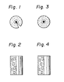
- Fig. 1 shows the orientation and cracks on a cross section of a pitch-based carbon fiber produced by a conventional method, wherein broken lines show the orientation of aligned carbon layers; and the right hand side of Fig. 2 is a side view of the fiber, and the left hand side thereof is a cross sectional view of the fiber showing schematically the alignment of carbon layers; Fig. 3 shows the orientation on a cross section of a pitch-based carbon fiber produced by the process of the present invention, wherein broken lines show the orientation of aligned carbon layers, and the right hand side of Fig. 4 is a side view of the fiber, and the left hand side thereof is a cross sectional view of the fiber showing schematically the alignment of carbon layers; and Fig. 5 shows a side view of an essential part of an example of the spinning apparatus of the present invention, which is partially written by a cross sectional view for the sake of a ready understanding of the structure.
- any mesophase pitch may be used as far as the pitches contain mesophase as the main component.
- the mesophase shows an optical anisotropy when examined on a polarized light microscope.
- the process of production of the mesophase pitch is not restricted to any specific process. Therefore, coal tar, naphtha tar, pyrolysis tar, decant oil, or pitch-like substances produced by distillation or thermal treatment of these heavy oils, or the like may be used as the starting material for the production of mesophase pitches.
- a mesophase pitch with a low softening temperature and with good spinning properties may readily be produced by 1) hydrogenating a pitch by mixing 1 weight part of the pitch with 2 - 3 weight parts of tetrahydroquinoline and heating the mixture at 400 - 450°C under an autogeneous pressure, and then 2) subjecting the hydrogenated pitch to a brief thermal treatment at a high temperature with bubbling of an inert gas.
- mesophase pitches are greatly dependent upon the softening temperature and the ratio of constituents.
- Mesophase pitches with a very high softening temperature are not preferable because they require a high spinning temperature which causes degradation and decomposition of pitches.
- pitches with a low softening temperature are used, if they are such that their main components are isotropic materials and if mesophase materials are present a small amount and dispersed as spheres, they show poor spinning properties because the pitches become heterogeneous due to the large difference in the viscosities of the isotropic and anisotropic materials in the spinning temperature range.
- mesophase pitches are those which contain more than 60 %, and more preferably more than 80 % of components showing an optical anisotropy when observed on a polarized light microscope.
- Mesophase pitches with softening temperature of 250 - 320 0 c are preferred.
- the use of a spinning nozzle hole with a complex cross section may also reduce the radial orientation of molecules and prevent the crack formation along the fiber axis at the carbonization stage.
- processing of a spinning nozzle hole require a special technique, and problems may arise concerning the precision of the spinning nozzle hole or cleaning up of the spinning nozzle after the use.
- the process of the present invention can use a conventional spinning nozzle with a circular spinning nozzle hole, requires no further processing to the spinning nozzle hole itself, and yet it can shift the orientation of molecules within the fibers only by giving a rotatory motion to the pitch just before the extrusion, and in this way, can completely prevent the crack formation along the fiber axis at the carbonization or graphitization stage.
- the means to give a rotatory motion to the pitch just before the extrusion are not restricted, but it is advantageous to use the apparatus of the present invention described below.
- the simplest means to give a rotatory motion to a pitch just before the extrusion is to use a spinning apparatus in which a plug member with an outer spiral groove is inserted into the pitch introducing tube which is connected substantially coaxial with a spinning nozzle hole, the plug member substantially fitting into the pitch introducing tube.
- the most preferred structure of the above apparatus is to use a pitch introducing tube having a circular cross section and a plug member having a circular cross section with the same or slightly smaller diameter as that of the pitch introducing tube.
- the shape of the plug member looks like a drill point or a worm gear.
- the diameter of a pitch introducing tube of a nozzle plate decreases as it nears the spinning nozzle hole and the top of the pitch introducing tube is conically shaped.
- the top of a drill point is also conically shaped but generally with an obtuse angle. Therefore, a small space can remain near the top of the pitch introducing tube, even after the insertion of a drill point into the pitch introducing tube.
- drill groove is a very loose spiral with a pitch of a few mm per rotation.
- the present invention has a high commercial value because, by the use of the process and the spinning apparatus of the present invention, the crack formation at the carbonization stage, which was the most troublesome problem in the spinning of mesophase pitch, can easily be prevented.
- the purpose of the present invention can be realized by use of a conventional nozzle plate without any special processing to the nozzle plate as far as it is equipped with a pitch introducing tube, by simply inserting into the pitch introducing tube, a plug member with a shape similar to a drill point. Also, the spinning nozzle hole can be cleaned up readily by the conventional method without any modification.
- carbon fibers without crack formation can be constantly produced independent of the characteristics of the mesophase pitch employed, spinning conditions, and the conditions of conversion to infusible state and carbonization.
- FIG. 5 A preferred embodiment of the apparatus of the present invention is exemplified by Fig. 5.
- FIG. 5 A side view of the structure of the essential part of an example of the spinning apparatus of the present invention is shown in Fig. 5, which partly shows a cross section for the sake of an easy understanding of the structure.
- the spinning apparatus consists of a nozzle plate 1 and a plug member 2.
- the nozzle plate 1 is shown in a cross sectional view.
- a spinning nozzle hole 3 is provided at the top of a pitch introducing tube 4.
- the pitch introducing tube 4 forms a conically shaped part 5 near the spinning nozzle hole 3, and the other side of the pitch introducing tube 4 is expanded to form a funnel-shaped part 6.
- the outer diameter of the plug member 2 is made substantially equal to the inner diameter of the pitch introducing tube 4.
- a spiral groove 7 is provided along the outer surface of the plug member 2, and a molten pitch, pumped downward, is given a rotatory motion as it flows down along this spiral groove.
- the apparatus of this invention has a spinning nozzle hole of 0.1 to 1 mm diameter and 0.5 to 1.5 mm length, above which is equipped with a pitch introducing tube with an inner diameter of 2 to 10 mm. More specifically, the apparatus shown in the Figure has a spinning nozzle hole of 0.25 mm diameter and 0.75 mm length, above which is equipped with a pitch introducing tube with an inner diameter of 2.5 mm.
- the cross sectional area of the pitch introducing tube is 10 to 1000 times of the cross sectional area of the spinning nozzle hole.
- the plug member 2 is a commercial drill point (Japanese Industrial Standard (JIS); straight shank drill) with an outer diameter of 2.5 mm.
- the pitch of the spiral groove of the plug member is 5 mm to 30 mm.
- the nozzle plate 1 was not processed specifically for the purpose of the present invention, but had been used formerly for spinning without insertion of a plug member 2 until the present invention.
- a coal tar pitch (200 g) and tetrahydroquinoline (400 g) was charged into a 1 liter autoclave and the mixture, after purging with nitrogen, was hydrogenated by heating for 30 min. at 420°C under an autogeneous pressure.
- a hydrogenated pitch was obtained by filtration of the treated liquid to eliminate insoluble materials, followed by removal of the solvent under reduced pressure.
- This hydrogenated pitch (100 g) was charged to a 300 ml polymerization flask, and was heated for 10 min. in a molten salt bath at 510°C, then it was heated further for 105 min. in a molten salt bath at 440°C, during these heat treatments, a stream of nitrogen was bubbled through at a rate of 5 liter/min.
- the spinning apparatus comprising (a) a nozzle plate having a pitch introducing tube (internal diameter of 2.5 mm) which has a spinning nozzle hole (diameter of 0.25 mm and a hole length of 0.75 mm) at the top and (b) a drill point (JIS straight shank drill) having outer diameter of 2.5 mm which was positioned within the pitch introducing tube by insertion, shown in Fig. 5 was used.
- the mesophase pitch prepared above was charged into the spinning apparatus and pitch fibers were produced by spinning at a temperature of 340°C at a spin rate of 400 m/min. They were made infusible by heating up to 320°C in the air, and then heated up to 1000°C under an atmosphere of nitrogen to give carbon fibers.
- Pitch fibers were produced by spinning a mesophase pitch with a softening temperature of 268°C, produced by the same method as Example 1, by the same nozzle plate as Example 1 but without insertion of a drill point, at a temperature of 340°C with a spinning rate of 400 m/min. They were made infusible and carbonized under the same conditions as those of Example 1, and then fifty monofilaments were randomly taken out and their appearances were examined at a magnification of 3000. They had an average diameter of 7.9 ⁇ , and 23 monofilaments out of fifty showed the presence of cracks to the direction parallel to the fiber axis.
- Two kinds of pitch fibers were produced by spinning the same mesophase pitch as Example 1 with a softening temperature of 268°C, by an apparatus with the same nozzle plate as Example 1 with insertion of the drill point, at a temperature of 340°C with a spinning rate of 200 m and 100 m/min., respectively.
- the carbon fibers thus produced had average diameters of 9.9 ⁇ and 12.4 ⁇ , respectively.
- Each fifty monofilaments were randomly taken out from each sample, and their appearances were examined at a magnification of 3000. In each case, none showed cracks along the fiber axis.
- Pitch fibers were produced from the same mesophase pitch as Example 1 with a softening temperature of 268°C, by an apparatus with the same nozzle plate as Example 1 with insertion of the drill point, at a temperature of 370°C with a spinning rate of 500 m/min. After rendered infusible and carbonized under the same conditions as those of Example 1, fifty monofilaments were randomly taken out, and their appearances were examined at a magnification of 3000. The carbon fibers thus produced had an average diameters of 10.1 ⁇ . None showed cracks along the fiber axis.
- a spinning pitch with a softening temperature of 285°C was produced by charging a hydrogenated pitch (200 g) which was hydrogenated by the same method as Example 1, into a 500 ml polymerization flask, heated for 10 min. in a molten salt bath kept at 510°C and then heated for 1 hr. in a molten salt bath kept at 460°C.
- Pitch fibers were produced from this pitch by an apparatus with the same nozzle plate as Example 1 with insertion of the drill point, at a temperature of 350°C with a spinning rate of 300 m/min. They were rendered infusible by heating up to 340°C in the air, and carbonized at 1000°C under the same conditions as those of Example 1.
- the carbon fibers thus produced had an average diameter of 11.6 ⁇ .
- Pitch fibers were produced from the same mesophase pitch as Example 1 with a softening temperature of 268°C, and by using a spinning apparatus with a spinning nozzle hole of 0.5 mm diameter and 1.0 mm length and a pitch introducing tube with an inner diameter of 2.5 mm to which was inserted the same drill point as Example 1, at a temperature of 340 0 C with a spinning rate of 300 m/min. They were rendered infusible and carbonized under the same conditions as those of Example 4. The carbon fibers thus produced had an average diameter of 13.4 ⁇ . When examined by the same way as Example 1, none of the fifty monofilaments showed the presence of cracks.
- Fig. 2 shows schematically the alignment of carbon layers in the carbon fiber of the Comparative Example 1 and the right hand side thereof shows the appearance of the fiber
- Fig. 4 shows schematically the alignment of carbon layers in the carbon fiber produced by Example 1 and the right hand side thereof shows the appearance of the fiber.
- Comparison of the two Figures shows that the general patterns of the alignment of carbon layers is similar to each other in that the carbon layers are aligned parallel to the fiber axis. However, as seen in Figs. 1 and 3, they differ each other in that while the aligned layers are oriented radially in Fig. 1 (Comparative Example 1), they have a curved orientation in a impeller-type in Fig. 3 (Example 1).
Abstract
Description
- The present invention relates to a process for producing carbon fibers with high strength and high modulus of elasticity such as Young's modulus from mesophase pitches and also relates to an apparatus suitable for the practice of the process. More specifically, the present invention relates to an excellent economical process for producing high quality carbon fibers from mesophase pitches by melt spinning, wherein the pitch is spun while giving a rotatory motion to the pitch, and to a very simple spinning apparatus used for the practice of the process. The characteristic feature of the apparatus of the present invention is that the apparatus contains a plug member having a spiral groove thereon, such as a drill point or a worm gear-like structure and the plug member is positioned within a path of pitch flow near a spinning nozzle hole so as to give a rotatory motion to the pitch.
- In the specification, the words "pitch-based carbon fibers" mean carbon fibers made from pitches.
- Carbon fibers are useful materials, and they are recently attracting attention and gathering concern as an important material of the next generation. The carbon fibers may be classified into two groups: a high performance grade carbon fiber with high strength and high modulus of elasticity which is used as composite materials in the fabrication of aircraft structures, sports goods, and the like, and a general purpose grade carbon fiber which is mainly used as heat insulator because of its low strength and modulus of elasticity.
- High performance grade carbon fibers have been produced mainly by spinning a polyacrylonitrile (PAN) fiber, converting the PAN fiber to infusible state under oxidizing conditions, and subsequently carbonizing or graphitizing it under an inert atmosphere. In contrast to these PAN-based carbon fibers, pitch-based carbon fibers which are produced from pitches, have been regarded as unsuitable for use as structure materials because of their lower strength and modulus of elasticity than PAN-based carbon fibers.
- Recently however, pitch-based carbon fibers recurred attention because of the low cost of the starting material and because high yield are attainable when they are rendered infusible or carbonized. Vigorous studies are currently made concerning the process for producing of high performance carbon fibers from pitches as the starting material. Several processes have been proposed which permit production of pitch-based carbon fibers showing equal properties to those of PAN-based carbon fibers or even showing far superior modulus of elasticity.
- Various processes for the production of pitch-based high performance carbon fibers have been elaborated: in one process (Japanese Patent Disclosure No. 196292/1983), pitches for spinning are produced by hydrogenation and subsequent thermal treatment; in another process (Japanese Patent Disclosure No. 113292/1983), pitches for spinning are produced by fractional solvent extraction of pitches and subsequent thermal treatment of specific fractions thus fractionated. In still another process (Japanese Patent Disclosure No. 86717/1983), pitches for spinning are produced by submitting pitches to a thermal treatment for a prolonged period of time at a relatively low temperature. A characteristic feature common to these processes is that all of the pitches for spinning are so-called mesophase pitch, which contain the mesophase showing an optical anisotropy when examined on a polarized light microscope as the main component.
- The mesophases described above are liquid crystals and are formed on heating heavy oils, tars or pitches. In the specification, the words "heavy oil" mean an oil having high boiling point and high specific gravity. It is considered that these mesophases show an optical anisotropy because planar aromatic molecules, developed by thermal polymerization, are aligned in a layered structure. When fibers are produced from such mesophase pitches by melt spinning, the planar aromatic molecules are aligned parallel to the fiber axis by the stress exerted on passing through a spinning nozzle hole. This oriented structure is not disturbed and.is maintained throughout the states of rendering the fibers infusible and their carbonization. Therefore, the carbon layers in the carbon fibers thus produced are also oriented along the fiber axis. Such highly oriented carbon fibers show high tensile strength, and when they are graphitized, they show high modulus of elasticity which is not attainable with PAN-based carbon fibers.
- In order to improve the performance of pitch-based carbon fibers, it is essential to produce and to use mesophase pitches which will permit formation of well-oriented planar aromatic molecules during the spinning stage, and most of the prior proposals on the processes for the production of high performance carbon fibers relate to processes for the production of high quality mesophase pitches.
- When fibers are spun with high quality mesophase pitches which induce well-oriented planar aromatic molecules, the molecules are oriented not only along the fiber axis, but also specifically on the cross section of the fiber. When a fiber is spun through an ordinary spinning nozzle hole with a circular cross section, it will produce a fiber with a circular cross section. When this cross section is examined, the planar aromatic molecules take the so-called radial orientation, which means that they are oriented radially from the center of the circle (Cf. Fig. 1). On carbonization, the planar aromatic molecules shrink to form carbon layers, while evaporating off volatile components. The degree of this shrinkage is markedly greater to the direction which is perpendicular to the plane of the planar aromatic molecules. Therefore, in the case of a fiber with a radial orientation, there is a large difference in the degree of shrinkage between that near the surface and that near the center of the fiber. This causes large cracks to take place along the fiber axis on carbonization (Cf. Figs. 1 and 2), and drastically lowers the commercial value.
- We also suffered from the crack formation along the fiber axis on carbonization, but after intensive studies aimed at solving these problems, we successfully came to the present invention.
- Thus, we found that the cracks can be completely prevented by a simple process and the characteristic feature of the process comprises giving to the molten pitch just before the extrusion, a rotatory motion substantially around the axis of the spinning nozzle hole. We also found a spinning apparatus with a simple construction which is suitable to the practice of the process described above.
- Therefore, the first object of the present invention is to provide a process for producing high performance pitch-based carbon fibers which can effectively prevent the crack formation, and the second object is to provide an apparatus for spinning of pitch-based carbon fibers which, though extremely simple in construction, can effectively prevent the crack formation.
- Thus, the gist of the first invention resides in a process for producing carbon fibers from a mesophase pitch by melt spinning which comprises extruding a molten mesophase pitch through a spinning nozzle hole, rendering the extruded pitch fibers thus obtained to an infusible state by heating under an oxidizing atmosphere and then carbonizing or graphitizing them by heating under an inert atmosphere, and characterized in that the spinning is performed by giving a rotatory motion to said molten mesophase pitch just before the extrusion substantially around the axis of said spinning nozzle hole; and the gist of the second invention resides in an apparatus for producing carbon fibers from a mesophase pitch by melt spinning comprising (a) a nozzle plate having a spinning nozzle hole and a pitch introducing tube which is connected in a substantially coaxial way to said spinning nozzle hole, and (b) plug member having an outer spiral groove and the outer size of said plug member is substantially equal to the inner size of said pitch introducing tube, and said plug member is inserted to said pitch introducing tube.
- Fig. 1 shows the orientation and cracks on a cross section of a pitch-based carbon fiber produced by a conventional method, wherein broken lines show the orientation of aligned carbon layers; and the right hand side of Fig. 2 is a side view of the fiber, and the left hand side thereof is a cross sectional view of the fiber showing schematically the alignment of carbon layers; Fig. 3 shows the orientation on a cross section of a pitch-based carbon fiber produced by the process of the present invention, wherein broken lines show the orientation of aligned carbon layers, and the right hand side of Fig. 4 is a side view of the fiber, and the left hand side thereof is a cross sectional view of the fiber showing schematically the alignment of carbon layers; and Fig. 5 shows a side view of an essential part of an example of the spinning apparatus of the present invention, which is partially written by a cross sectional view for the sake of a ready understanding of the structure.
- Any mesophase pitch may be used as far as the pitches contain mesophase as the main component. The mesophase shows an optical anisotropy when examined on a polarized light microscope. The process of production of the mesophase pitch is not restricted to any specific process. Therefore, coal tar, naphtha tar, pyrolysis tar, decant oil, or pitch-like substances produced by distillation or thermal treatment of these heavy oils, or the like may be used as the starting material for the production of mesophase pitches.
- As described before, several processes have been known to the art concerning the process of production of mesophase pitches. For example, a mesophase pitch with a low softening temperature and with good spinning properties may readily be produced by 1) hydrogenating a pitch by mixing 1 weight part of the pitch with 2 - 3 weight parts of tetrahydroquinoline and heating the mixture at 400 - 450°C under an autogeneous pressure, and then 2) subjecting the hydrogenated pitch to a brief thermal treatment at a high temperature with bubbling of an inert gas.
- The spinning properties of mesophase pitches are greatly dependent upon the softening temperature and the ratio of constituents. Mesophase pitches with a very high softening temperature are not preferable because they require a high spinning temperature which causes degradation and decomposition of pitches. Even if pitches with a low softening temperature are used, if they are such that their main components are isotropic materials and if mesophase materials are present a small amount and dispersed as spheres, they show poor spinning properties because the pitches become heterogeneous due to the large difference in the viscosities of the isotropic and anisotropic materials in the spinning temperature range. When isotropic pitches which do not contain mesophase moiety are spun, it will not meet the object of the present invention, because the aromatic molecules in this case are not large enough to orient themselves distinctly by the stress on passing through the spinning nozzle hole. Preferred mesophase pitches are those which contain more than 60 %, and more preferably more than 80 % of components showing an optical anisotropy when observed on a polarized light microscope. Mesophase pitches with softening temperature of 250 - 3200c are preferred.
- It has been known to the art that the crack formation during conversion to infusible state, carbonization, or graphitization step of a spun pitch may be prevented by raising the spinning temperature, which induce the molecules within the fiber to take an onion-like orientation instead of a radial orientation. However, when mesophase pitches which themselves show high softening temperature of 250 - 300°C are spun by the process just described above, the spinning temperature should be maintained, at least, above 350°C to prevent the crack formation. At this temperature, many organic compounds will decompose, and when degradation and decomposition of pitches are taken into account, it is not necessarily a preferred method to use a higher temperature in order to establish an onion-like orientation, since degradation and decomposition of the pitches give tremendous adverse effects on the properties of carbon fiber products. The use of a spinning nozzle hole with a complex cross section may also reduce the radial orientation of molecules and prevent the crack formation along the fiber axis at the carbonization stage. In this case, however, processing of a spinning nozzle hole require a special technique, and problems may arise concerning the precision of the spinning nozzle hole or cleaning up of the spinning nozzle after the use.
- On the other hand, the process of the present invention can use a conventional spinning nozzle with a circular spinning nozzle hole, requires no further processing to the spinning nozzle hole itself, and yet it can shift the orientation of molecules within the fibers only by giving a rotatory motion to the pitch just before the extrusion, and in this way, can completely prevent the crack formation along the fiber axis at the carbonization or graphitization stage.
- The means to give a rotatory motion to the pitch just before the extrusion are not restricted, but it is advantageous to use the apparatus of the present invention described below.
- Thus, the simplest means to give a rotatory motion to a pitch just before the extrusion is to use a spinning apparatus in which a plug member with an outer spiral groove is inserted into the pitch introducing tube which is connected substantially coaxial with a spinning nozzle hole, the plug member substantially fitting into the pitch introducing tube.
- The most preferred structure of the above apparatus is to use a pitch introducing tube having a circular cross section and a plug member having a circular cross section with the same or slightly smaller diameter as that of the pitch introducing tube. In this case, the shape of the plug member looks like a drill point or a worm gear.
- Thus, when a simple construction is desired, it will be realized by connecting above the spinning nozzle hole, a pitch introducing tube with a diameter of a few mm and a length of ten and a few to a few tens mm, into which a conventional drill point commonly used as a tool or worm gear is inserted.
- Generally, the diameter of a pitch introducing tube of a nozzle plate decreases as it nears the spinning nozzle hole and the top of the pitch introducing tube is conically shaped. The top of a drill point is also conically shaped but generally with an obtuse angle. Therefore, a small space can remain near the top of the pitch introducing tube, even after the insertion of a drill point into the pitch introducing tube. In general, drill groove is a very loose spiral with a pitch of a few mm per rotation. It was hardly predictable that such a slow rotation of the flow at a rate of a few mm per rotation in the pitch introducing tube would influence the orientation of the produced fibers, because it is believed that the molecules in the spun fibers are oriented by the stress at the spinning nozzle hole with a diameter as small as 0.1 - 0.5 mm. However, when fiber spun from the apparatus of this invention was carbonized or graphitized and its appearance was examined on a scanning electron microscope, it was found, as shown in Figs. 3 and 4, that no crack formation occurred along the fiber axis. Further, as shown in Fig. 3, examination of the orientation of carbon layers on the cross section showed that even though the orientation looked like radial, it nevertheless was influenced by the effect of spiral rotation effect within the pitch introducing tube, and it was found to have a characteristic structure in which the orientation of carbon layer was curved as an impeller blade of a centrifugal pump.
- It has not been elucidated fully why such a slow rotation, caused by a drill point inserted into a pitch introducing tube should result in such a remarkable effect. At present, we consider that as the cross sectional area is reduced to 1/10 - 1/1000, usually 1/100 - 1/1000 in the conical portion of the pitch introducing tube, the flow would rotate very rapidly at the spinning nozzle hole in just the same manner as a flow rotates quite rapidly at the conical part of a cyclone separator.
- It is as yet impossible to offer a precise reason why a shift of orientation from a radial to impeller-type can completely prevent crack formation at the carbonization stage, it may be assumed that the latter orientation has an effect similar to that of the onion-like orientation.
- The present invention has a high commercial value because, by the use of the process and the spinning apparatus of the present invention, the crack formation at the carbonization stage, which was the most troublesome problem in the spinning of mesophase pitch, can easily be prevented. Moreover, the purpose of the present invention can be realized by use of a conventional nozzle plate without any special processing to the nozzle plate as far as it is equipped with a pitch introducing tube, by simply inserting into the pitch introducing tube, a plug member with a shape similar to a drill point. Also, the spinning nozzle hole can be cleaned up readily by the conventional method without any modification.
- By the use of the process of the present invention, carbon fibers without crack formation can be constantly produced independent of the characteristics of the mesophase pitch employed, spinning conditions, and the conditions of conversion to infusible state and carbonization.
- A preferred embodiment of the apparatus of the present invention is exemplified by Fig. 5. A side view of the structure of the essential part of an example of the spinning apparatus of the present invention is shown in Fig. 5, which partly shows a cross section for the sake of an easy understanding of the structure.
- The spinning apparatus consists of a nozzle plate 1 and a
plug member 2. In the Figure, for the convenience of explanation, the nozzle plate 1 is shown in a cross sectional view. A spinningnozzle hole 3 is provided at the top of apitch introducing tube 4. Thepitch introducing tube 4 forms a conically shapedpart 5 near the spinningnozzle hole 3, and the other side of thepitch introducing tube 4 is expanded to form a funnel-shapedpart 6. The outer diameter of theplug member 2 is made substantially equal to the inner diameter of thepitch introducing tube 4. Aspiral groove 7 is provided along the outer surface of theplug member 2, and a molten pitch, pumped downward, is given a rotatory motion as it flows down along this spiral groove. In general, the apparatus of this invention has a spinning nozzle hole of 0.1 to 1 mm diameter and 0.5 to 1.5 mm length, above which is equipped with a pitch introducing tube with an inner diameter of 2 to 10 mm. More specifically, the apparatus shown in the Figure has a spinning nozzle hole of 0.25 mm diameter and 0.75 mm length, above which is equipped with a pitch introducing tube with an inner diameter of 2.5 mm. The cross sectional area of the pitch introducing tube is 10 to 1000 times of the cross sectional area of the spinning nozzle hole. Theplug member 2 is a commercial drill point (Japanese Industrial Standard (JIS); straight shank drill) with an outer diameter of 2.5 mm. The pitch of the spiral groove of the plug member is 5 mm to 30 mm. The nozzle plate 1 was not processed specifically for the purpose of the present invention, but had been used formerly for spinning without insertion of aplug member 2 until the present invention. - The process of the present invention will be explained in more detail by the following Examples.
- A coal tar pitch (200 g) and tetrahydroquinoline (400 g) was charged into a 1 liter autoclave and the mixture, after purging with nitrogen, was hydrogenated by heating for 30 min. at 420°C under an autogeneous pressure. A hydrogenated pitch was obtained by filtration of the treated liquid to eliminate insoluble materials, followed by removal of the solvent under reduced pressure. This hydrogenated pitch (100 g) was charged to a 300 ml polymerization flask, and was heated for 10 min. in a molten salt bath at 510°C, then it was heated further for 105 min. in a molten salt bath at 440°C, during these heat treatments, a stream of nitrogen was bubbled through at a rate of 5 liter/min. This process afforded a pitch for spinning with a softening temperature of 268°C. On examination of this pitch on a polarized light microscope, it was found that the main component of the pitch is a mesophase showing an optical anisotropy, and a small amount of isotropic material was dispersed as spheres in the pitch.
- The spinning apparatus comprising (a) a nozzle plate having a pitch introducing tube (internal diameter of 2.5 mm) which has a spinning nozzle hole (diameter of 0.25 mm and a hole length of 0.75 mm) at the top and (b) a drill point (JIS straight shank drill) having outer diameter of 2.5 mm which was positioned within the pitch introducing tube by insertion, shown in Fig. 5 was used. The mesophase pitch prepared above was charged into the spinning apparatus and pitch fibers were produced by spinning at a temperature of 340°C at a spin rate of 400 m/min. They were made infusible by heating up to 320°C in the air, and then heated up to 1000°C under an atmosphere of nitrogen to give carbon fibers. Fifty monofilaments were randomly taken out from the above carbon fiber sample and they were examined by scanning electron microscope at a magnification of 3000. It was found that they had an average diameter of 7.8 µ, and none of the above fifty samples showed the presence of cracks. The structure of the cross section of this sample had a impeller-type orientation as shown in Fig. 3. Comparative Example 1
- Pitch fibers were produced by spinning a mesophase pitch with a softening temperature of 268°C, produced by the same method as Example 1, by the same nozzle plate as Example 1 but without insertion of a drill point, at a temperature of 340°C with a spinning rate of 400 m/min. They were made infusible and carbonized under the same conditions as those of Example 1, and then fifty monofilaments were randomly taken out and their appearances were examined at a magnification of 3000. They had an average diameter of 7.9 µ, and 23 monofilaments out of fifty showed the presence of cracks to the direction parallel to the fiber axis. Because only one side of the sample could be examined by a scanning electron microscope, the fact that 23 out of fifty samples showed cracks may be considered as suggesting that almost all samples had cracks. The structure of the cross section of these samples had a radial orientation as shown in Fig. 1.
- Two kinds of pitch fibers were produced by spinning the same mesophase pitch as Example 1 with a softening temperature of 268°C, by an apparatus with the same nozzle plate as Example 1 with insertion of the drill point, at a temperature of 340°C with a spinning rate of 200 m and 100 m/min., respectively. When rendered infusible and carbonized under the same conditions as those of Example 1, the carbon fibers thus produced had average diameters of 9.9 µ and 12.4 µ, respectively. Each fifty monofilaments were randomly taken out from each sample, and their appearances were examined at a magnification of 3000. In each case, none showed cracks along the fiber axis.
- Pitch fibers were produced from the same mesophase pitch as Example 1 with a softening temperature of 268°C, by an apparatus with the same nozzle plate as Example 1 with insertion of the drill point, at a temperature of 370°C with a spinning rate of 500 m/min. After rendered infusible and carbonized under the same conditions as those of Example 1, fifty monofilaments were randomly taken out, and their appearances were examined at a magnification of 3000. The carbon fibers thus produced had an average diameters of 10.1 µ. None showed cracks along the fiber axis.
- A spinning pitch with a softening temperature of 285°C was produced by charging a hydrogenated pitch (200 g) which was hydrogenated by the same method as Example 1, into a 500 ml polymerization flask, heated for 10 min. in a molten salt bath kept at 510°C and then heated for 1 hr. in a molten salt bath kept at 460°C. Pitch fibers were produced from this pitch by an apparatus with the same nozzle plate as Example 1 with insertion of the drill point, at a temperature of 350°C with a spinning rate of 300 m/min. They were rendered infusible by heating up to 340°C in the air, and carbonized at 1000°C under the same conditions as those of Example 1. The carbon fibers thus produced had an average diameter of 11.6µ. When the appearances of fifty monofilaments were examined in the same way as Example 1, none of the fifty monofilaments showed the presence of cracks.
- Pitch fibers were produced from the same mesophase pitch as Example 1 with a softening temperature of 268°C, and by using a spinning apparatus with a spinning nozzle hole of 0.5 mm diameter and 1.0 mm length and a pitch introducing tube with an inner diameter of 2.5 mm to which was inserted the same drill point as Example 1, at a temperature of 3400C with a spinning rate of 300 m/min. They were rendered infusible and carbonized under the same conditions as those of Example 4. The carbon fibers thus produced had an average diameter of 13.4 µ. When examined by the same way as Example 1, none of the fifty monofilaments showed the presence of cracks.
- The left hand side of Fig. 2 shows schematically the alignment of carbon layers in the carbon fiber of the Comparative Example 1 and the right hand side thereof shows the appearance of the fiber, and the left hand side of Fig. 4 shows schematically the alignment of carbon layers in the carbon fiber produced by Example 1 and the right hand side thereof shows the appearance of the fiber. Comparison of the two Figures shows that the general patterns of the alignment of carbon layers is similar to each other in that the carbon layers are aligned parallel to the fiber axis. However, as seen in Figs. 1 and 3, they differ each other in that while the aligned layers are oriented radially in Fig. 1 (Comparative Example 1), they have a curved orientation in a impeller-type in Fig. 3 (Example 1).
Claims (9)
Applications Claiming Priority (2)
| Application Number | Priority Date | Filing Date | Title |
|---|---|---|---|
| JP60007699A JPH0637725B2 (en) | 1985-01-19 | 1985-01-19 | Carbon fiber manufacturing method |
| JP7699/85 | 1985-01-19 |
Publications (3)
| Publication Number | Publication Date |
|---|---|
| EP0189150A2 true EP0189150A2 (en) | 1986-07-30 |
| EP0189150A3 EP0189150A3 (en) | 1987-04-15 |
| EP0189150B1 EP0189150B1 (en) | 1990-04-18 |
Family
ID=11673011
Family Applications (1)
| Application Number | Title | Priority Date | Filing Date |
|---|---|---|---|
| EP86100614A Expired - Lifetime EP0189150B1 (en) | 1985-01-19 | 1986-01-17 | Process and apparatus for producing carbon fibers |
Country Status (6)
| Country | Link |
|---|---|
| US (1) | US4818449A (en) |
| EP (1) | EP0189150B1 (en) |
| JP (1) | JPH0637725B2 (en) |
| AU (1) | AU576654B2 (en) |
| CA (1) | CA1284261C (en) |
| DE (1) | DE3670515D1 (en) |
Cited By (2)
| Publication number | Priority date | Publication date | Assignee | Title |
|---|---|---|---|---|
| WO2009074837A1 (en) * | 2007-12-10 | 2009-06-18 | Dtx Technologies Llc | Pitch production, fractionation and high softening point pitch |
| EP2832902A1 (en) * | 2013-08-02 | 2015-02-04 | NANOVAL GmbH & Co. KG | Optimisation of a spinning nozzle for spinning filaments from a spinning material |
Families Citing this family (10)
| Publication number | Priority date | Publication date | Assignee | Title |
|---|---|---|---|---|
| JPH0791697B2 (en) * | 1986-10-21 | 1995-10-04 | 株式会社ペトカ | Carbon fiber manufacturing method |
| JPH01118622A (en) * | 1987-10-28 | 1989-05-11 | Ube Ind Ltd | High-strength and high-modulus carbon fiber |
| US5202072A (en) * | 1989-02-16 | 1993-04-13 | E. I. Du Pont De Nemours And Company | Pitch carbon fiber spinning process |
| US5437927A (en) * | 1989-02-16 | 1995-08-01 | Conoco Inc. | Pitch carbon fiber spinning process |
| US5169584A (en) * | 1989-02-16 | 1992-12-08 | E. I. Du Pont De Nemours And Company | Method of making small diameter high strength carbon fibers |
| JP2894880B2 (en) * | 1991-09-13 | 1999-05-24 | 株式会社ペトカ | Spinnerets for pitch-based carbon fiber spinning |
| US6800364B2 (en) * | 2002-06-28 | 2004-10-05 | Ucar Carbon Company Inc. | Isotropic pitch-based materials for thermal insulation |
| US20040041291A1 (en) * | 2002-08-27 | 2004-03-04 | Ucar Carbon Company Inc. | Process of making carbon electrodes |
| JP5039795B2 (en) * | 2007-02-12 | 2012-10-03 | ストラタシス,インコーポレイテッド | Viscous pump for extrusion deposition systems. |
| CN104047066B (en) * | 2014-07-01 | 2016-08-17 | 陕西天策新材料科技有限公司 | A kind of mesophase pitch melt spinning method |
Citations (4)
| Publication number | Priority date | Publication date | Assignee | Title |
|---|---|---|---|---|
| CH334039A (en) * | 1954-09-22 | 1958-11-15 | Siemens Ag | Injection nozzle in an injection molding machine for thermoplastics |
| GB884465A (en) * | 1959-07-24 | 1961-12-13 | Arthur Hehl | Improvements in or relating to injection moulding machines |
| DE2017710A1 (en) * | 1969-04-18 | 1970-10-22 | Montecatini Edison S.P.A., Mailand (Italien) | Improved extruder to avoid marbling effects on extruded plastic objects |
| US4331620A (en) * | 1980-02-25 | 1982-05-25 | Exxon Research & Engineering Co. | Process for producing carbon fibers from heat treated pitch |
Family Cites Families (8)
| Publication number | Priority date | Publication date | Assignee | Title |
|---|---|---|---|---|
| DE2462369C2 (en) * | 1973-12-11 | 1984-05-17 | Union Carbide Corp., New York, N.Y. | Process for the preparation of a pitch containing mesophase |
| US4076481A (en) * | 1975-01-15 | 1978-02-28 | Sussex Plastics Engineering, Inc. | Annular extrusion die |
| US4376747A (en) * | 1980-12-11 | 1983-03-15 | Union Carbide Corporation | Process for controlling the cross-sectional structure of mesophase pitch derived fibers |
| JPS58113292A (en) * | 1981-12-28 | 1983-07-06 | Mitsubishi Chem Ind Ltd | Preparation of raw material pitch for production of carbon product |
| JPS602352B2 (en) * | 1982-05-12 | 1985-01-21 | 工業技術院長 | Production method of Primesoface carbonaceous material |
| US4504454A (en) * | 1983-03-28 | 1985-03-12 | E. I. Du Pont De Nemours And Company | Process of spinning pitch-based carbon fibers |
| US4576811A (en) * | 1983-11-03 | 1986-03-18 | E. I. Du Pont De Nemours And Company | Process for adjusting the fiber structure of mesophase pitch fibers |
| JPS60259609A (en) * | 1984-06-01 | 1985-12-21 | Nippon Oil Co Ltd | Nozzle for spinning |
-
1985
- 1985-01-19 JP JP60007699A patent/JPH0637725B2/en not_active Expired - Lifetime
-
1986
- 1986-01-13 AU AU52228/86A patent/AU576654B2/en not_active Ceased
- 1986-01-13 US US06/818,499 patent/US4818449A/en not_active Expired - Fee Related
- 1986-01-16 CA CA000499690A patent/CA1284261C/en not_active Expired - Fee Related
- 1986-01-17 EP EP86100614A patent/EP0189150B1/en not_active Expired - Lifetime
- 1986-01-17 DE DE8686100614T patent/DE3670515D1/en not_active Expired - Fee Related
Patent Citations (4)
| Publication number | Priority date | Publication date | Assignee | Title |
|---|---|---|---|---|
| CH334039A (en) * | 1954-09-22 | 1958-11-15 | Siemens Ag | Injection nozzle in an injection molding machine for thermoplastics |
| GB884465A (en) * | 1959-07-24 | 1961-12-13 | Arthur Hehl | Improvements in or relating to injection moulding machines |
| DE2017710A1 (en) * | 1969-04-18 | 1970-10-22 | Montecatini Edison S.P.A., Mailand (Italien) | Improved extruder to avoid marbling effects on extruded plastic objects |
| US4331620A (en) * | 1980-02-25 | 1982-05-25 | Exxon Research & Engineering Co. | Process for producing carbon fibers from heat treated pitch |
Cited By (2)
| Publication number | Priority date | Publication date | Assignee | Title |
|---|---|---|---|---|
| WO2009074837A1 (en) * | 2007-12-10 | 2009-06-18 | Dtx Technologies Llc | Pitch production, fractionation and high softening point pitch |
| EP2832902A1 (en) * | 2013-08-02 | 2015-02-04 | NANOVAL GmbH & Co. KG | Optimisation of a spinning nozzle for spinning filaments from a spinning material |
Also Published As
| Publication number | Publication date |
|---|---|
| US4818449A (en) | 1989-04-04 |
| EP0189150B1 (en) | 1990-04-18 |
| AU5222886A (en) | 1986-07-24 |
| AU576654B2 (en) | 1988-09-01 |
| JPH0637725B2 (en) | 1994-05-18 |
| DE3670515D1 (en) | 1990-05-23 |
| JPS61167022A (en) | 1986-07-28 |
| EP0189150A3 (en) | 1987-04-15 |
| CA1284261C (en) | 1991-05-21 |
Similar Documents
| Publication | Publication Date | Title |
|---|---|---|
| EP0189150B1 (en) | Process and apparatus for producing carbon fibers | |
| US4115527A (en) | Production of carbon fibers having high anisotropy | |
| CA1173608A (en) | Process for preparation of carbon fibers having structure reflected in cross sectional view thereof as random mosaic | |
| JPS6246644B2 (en) | ||
| EP0084275B1 (en) | Process for the production of pitch-derived carbon fibers | |
| EP0338212B1 (en) | Ultra-high modulus and high tensile strength carbon fibre | |
| KR930006814B1 (en) | Pitch for the production of carbon fibers | |
| EP0349307A2 (en) | Process for producing pitch-based carbon fibres superior in compressive physical properties | |
| US5968435A (en) | Process for manufacturing pitch-type carbon fiber | |
| JPS59196390A (en) | Preparation of pitch for carbon fiber | |
| JPS602352B2 (en) | Production method of Primesoface carbonaceous material | |
| JPH0781211B2 (en) | Carbon fiber manufacturing method | |
| US4608150A (en) | Pitch material for carbonaceous body and a method for the preparation thereof | |
| JPH0148312B2 (en) | ||
| JPH0545685B2 (en) | ||
| JPH0144805B2 (en) | ||
| JPH0718057B2 (en) | Pitch-based fiber manufacturing method | |
| JPH07116643B2 (en) | Carbon fiber manufacturing method | |
| JPS6175821A (en) | Production of pitch carbon fiber | |
| JPS6112919A (en) | Production of pitch carbon fiber | |
| JPH0518922B2 (en) | ||
| JPS62170527A (en) | Production of pitch-based carbon fiber | |
| JPS62116688A (en) | Manufacture of carbon fiber spinning pitch | |
| JPH0811844B2 (en) | Method for producing pitch-based carbon fiber | |
| JP2953445B2 (en) | Carbon fiber production method |
Legal Events
| Date | Code | Title | Description |
|---|---|---|---|
| PUAI | Public reference made under article 153(3) epc to a published international application that has entered the european phase |
Free format text: ORIGINAL CODE: 0009012 |
|
| AK | Designated contracting states |
Kind code of ref document: A2 Designated state(s): DE FR GB IT NL |
|
| PUAL | Search report despatched |
Free format text: ORIGINAL CODE: 0009013 |
|
| AK | Designated contracting states |
Kind code of ref document: A3 Designated state(s): DE FR GB IT NL |
|
| 17P | Request for examination filed |
Effective date: 19871014 |
|
| 17Q | First examination report despatched |
Effective date: 19890707 |
|
| RAP1 | Party data changed (applicant data changed or rights of an application transferred) |
Owner name: MARUZEN PETROCHEMICAL CO., LTD. Owner name: DIRECTOR-GENERAL OF AGENCY OF INDUSTRIAL SCIENCE A |
|
| GRAA | (expected) grant |
Free format text: ORIGINAL CODE: 0009210 |
|
| AK | Designated contracting states |
Kind code of ref document: B1 Designated state(s): DE FR GB IT NL |
|
| ITF | It: translation for a ep patent filed |
Owner name: BUGNION S.P.A. |
|
| REF | Corresponds to: |
Ref document number: 3670515 Country of ref document: DE Date of ref document: 19900523 |
|
| ET | Fr: translation filed | ||
| ITTA | It: last paid annual fee | ||
| PLBE | No opposition filed within time limit |
Free format text: ORIGINAL CODE: 0009261 |
|
| STAA | Information on the status of an ep patent application or granted ep patent |
Free format text: STATUS: NO OPPOSITION FILED WITHIN TIME LIMIT |
|
| 26N | No opposition filed | ||
| PGFP | Annual fee paid to national office [announced via postgrant information from national office to epo] |
Ref country code: GB Payment date: 19941230 Year of fee payment: 10 |
|
| PGFP | Annual fee paid to national office [announced via postgrant information from national office to epo] |
Ref country code: FR Payment date: 19950116 Year of fee payment: 10 |
|
| PGFP | Annual fee paid to national office [announced via postgrant information from national office to epo] |
Ref country code: NL Payment date: 19950131 Year of fee payment: 10 |
|
| PGFP | Annual fee paid to national office [announced via postgrant information from national office to epo] |
Ref country code: DE Payment date: 19950330 Year of fee payment: 10 |
|
| PG25 | Lapsed in a contracting state [announced via postgrant information from national office to epo] |
Ref country code: GB Effective date: 19960117 |
|
| PG25 | Lapsed in a contracting state [announced via postgrant information from national office to epo] |
Ref country code: NL Effective date: 19960801 |
|
| GBPC | Gb: european patent ceased through non-payment of renewal fee |
Effective date: 19960117 |
|
| PG25 | Lapsed in a contracting state [announced via postgrant information from national office to epo] |
Ref country code: FR Effective date: 19960930 |
|
| NLV4 | Nl: lapsed or anulled due to non-payment of the annual fee |
Effective date: 19960801 |
|
| PG25 | Lapsed in a contracting state [announced via postgrant information from national office to epo] |
Ref country code: DE Effective date: 19961001 |
|
| REG | Reference to a national code |
Ref country code: FR Ref legal event code: ST |
|
| PG25 | Lapsed in a contracting state [announced via postgrant information from national office to epo] |
Ref country code: IT Free format text: LAPSE BECAUSE OF NON-PAYMENT OF DUE FEES Effective date: 20050117 |