EP0189152B1 - A device for the separation of the lighter fraction from the heavier fraction of a liquid sample - Google Patents
A device for the separation of the lighter fraction from the heavier fraction of a liquid sample Download PDFInfo
- Publication number
- EP0189152B1 EP0189152B1 EP86100618A EP86100618A EP0189152B1 EP 0189152 B1 EP0189152 B1 EP 0189152B1 EP 86100618 A EP86100618 A EP 86100618A EP 86100618 A EP86100618 A EP 86100618A EP 0189152 B1 EP0189152 B1 EP 0189152B1
- Authority
- EP
- European Patent Office
- Prior art keywords
- membrane
- evacuated
- receptacle
- cannula
- communication means
- Prior art date
- Legal status (The legal status is an assumption and is not a legal conclusion. Google has not performed a legal analysis and makes no representation as to the accuracy of the status listed.)
- Expired - Lifetime
Links
Images


Classifications
-
- B—PERFORMING OPERATIONS; TRANSPORTING
- B01—PHYSICAL OR CHEMICAL PROCESSES OR APPARATUS IN GENERAL
- B01D—SEPARATION
- B01D61/00—Processes of separation using semi-permeable membranes, e.g. dialysis, osmosis or ultrafiltration; Apparatus, accessories or auxiliary operations specially adapted therefor
- B01D61/14—Ultrafiltration; Microfiltration
- B01D61/18—Apparatus therefor
-
- G—PHYSICS
- G01—MEASURING; TESTING
- G01N—INVESTIGATING OR ANALYSING MATERIALS BY DETERMINING THEIR CHEMICAL OR PHYSICAL PROPERTIES
- G01N33/00—Investigating or analysing materials by specific methods not covered by groups G01N1/00 - G01N31/00
- G01N33/48—Biological material, e.g. blood, urine; Haemocytometers
- G01N33/483—Physical analysis of biological material
- G01N33/487—Physical analysis of biological material of liquid biological material
- G01N33/49—Blood
- G01N33/491—Blood by separating the blood components
-
- Y—GENERAL TAGGING OF NEW TECHNOLOGICAL DEVELOPMENTS; GENERAL TAGGING OF CROSS-SECTIONAL TECHNOLOGIES SPANNING OVER SEVERAL SECTIONS OF THE IPC; TECHNICAL SUBJECTS COVERED BY FORMER USPC CROSS-REFERENCE ART COLLECTIONS [XRACs] AND DIGESTS
- Y10—TECHNICAL SUBJECTS COVERED BY FORMER USPC
- Y10T—TECHNICAL SUBJECTS COVERED BY FORMER US CLASSIFICATION
- Y10T436/00—Chemistry: analytical and immunological testing
- Y10T436/25—Chemistry: analytical and immunological testing including sample preparation
- Y10T436/25375—Liberation or purification of sample or separation of material from a sample [e.g., filtering, centrifuging, etc.]
- Y10T436/255—Liberation or purification of sample or separation of material from a sample [e.g., filtering, centrifuging, etc.] including use of a solid sorbent, semipermeable membrane, or liquid extraction
Description
- The present invention relates to a device for the separation of the lighter fraction from the heavier fraction of a liquid sample according the preamble of claim 1. More particularly this invention relates to a self-contained device for the separation of the liquid component from the cellular component of a blood sample without the use of a centrifuge, an auxiliary circulating system, an auxiliary pump or the like.
- A common method of obtaining a blood sample involves the use of a two-cannula needle assembly and an evacuated glass tube having a pierceable stopper. The method involves inserting one cannula of the needle assembly into the subject's vein and piercing the stopper of the evacuated glass tube with the other cannula of the needle assembly, thereby establishing fluid communication between the vein and the interior of the glass tube. Due to the lower pressures within the evacuated glass tube blood is drawn from the subject into the tube. Evacuated tubes and needle assemblies for use therewith are described in U.S. Patent No. 3,469,572. Such devices are commercially available under the VACUTAINER Brand name from Becton, Dickinson and Company, Paramus, New Jersey.
- The blood sample, in the evacuated glass tube, may then be placed in a centrifuge and centrifuged until the more dense cellular component of the blood sample is driven to the bottom of the tube and the less dense plasma is positioned at the top of the sample. The stopper from the tube may then be removed and the plasma sample poured off for subsequent testing. If serum is desired the blood sample is allowed to clot before centrifuging the blood sample.
- U.S. Patent No. 4,057,499 to Buono teaches the collection of a plasma or serum sample using a sampling member having a hollow interior for the collection of liquid and a piston connected to one end of the sampling member. The piston includes a lip for forming a seal with the interior walls of the sample containing glass tube and an interior portion contains a filter and a one-way valve. In use, a blood sample, in a glass tube, is centrifuged to separate the liquid and the cellular phases and then the device of Buono is placed in the tube and forced along the inner tube surface so that the piston passes through the liquid portion of the sample forcing the liquid portion through the filter and through the valve into the hollow interior of the device. The device containing a portion of the liquid sample is then removed from the glass tube. Buono teaches that it is desirable to physically separate the liquid phase of the sample from the cellular phase to prevent deleterious chemical interaction between the two. Accordingly, Buono teaches the use of a centrifuge and a separate filtering apparatus to obtain the plasma or serum sample.
- It is believed that forcing a filter membrane through a blood sample, without the use of a centrifuge, is not a practical method of separating the liquid and the cellular components because the filter membrane would soon become caked with the cellular components and unable to perform its task as a filter. Accordingly, it is believed that if the liquid phase of the blood sample is to be filtered from the cellular portion of the blood sample, without the use of a centrifuge, a cross-flow filter arrangement should be provided. In a cross-flow arrangement, the blood sample flows across the surface of the filter membrane in a direction parallel to the major axis of the membrane while a secondary force provides a pressure differential between the blood side of the membrane and the liquid side so that the liquid phase will pass through the membrane. The cross-flow method of filtration is superior because when the blood sample is caused to flow in parallel relationship across the filter membrane there is substantially less tendency for the membrane to be clogged by the cellular portion of the blood sample and therefore allowing the blood to be filtered without the use of a centrifuge.
- U.S. Patent Nos. 3,211,645; 4,191,182; 4,212,742 and 4,343,705 teach various devices for the filtration of liquid using a cross-flow technique. In each of these patents, the devices utilized require an applied pressure driving force from a separate source across the membrane filter in order to bring about the proper separation. That is, a separate pumping and/or circulating device must be used in conjunction with the cross-flow filter of the known devices.
- From US-A-3 705 100, from which claim 1 starts, there is known a blood fractionating apparatus of the cross-flow filter type comprising two receptacles for collecting the different blood fractions. The apparatus includes a housing with an interior cavity divided by a separator (filtering) membrane into a first portion and a second portion. The liquid sample is stored in a syringe attached by means of a Luer lock fastening means to the housing for providing fluid communication via an inlet port between the first portion of the cavity and the liquid sample. Outlet ports or first and second communication means, respectively, are provided for fluid communication between the first and second portions of the cavity and the first and second receptacles. The liquid sample to be fractionated under pressure flows along and through the filtering membrane in order to filter the liquid. The fractions flow via the outlet ports out of the portions of the cavity of the housing into the first or second receptacles, respectively. Blood fractionating by means of the known apparatus is rather fussy since the liquid sample at first must be sucked into the hypodermic syringe and, thereafter, injected into the housing for fractionating the blood. This can consume valuable time in emergency situations wherein the liquid phase of the patient's blood sample must be analysed properly in order to diagnose the problem and/or to provide proper emergency treatment. In these situations, it is desirable to provide a device for the separation of the liquid phase of the blood sample from the cellular phase immediately upon the drawing of the blood sample without further steps. Furthermore, in the known apparatus the common evacuated blood collection receptacles can not be used.
- From EP-A-0 184 852 the priority date of which is prior to while the publication date is later than the priority date of the instant application, a device for fractionating blood is known which includes a receptacle with two evacuated chambers. Within the receptacle there is provided a separation assembly consisting of two spaced opposed walls and a cavity therebetween devided by a separator membrane into two portion. Each evacuated chamber is connected to one portion of the cavity. The receptacle is closed by a pierceable stopper also closing an inlet means of the cavity. When piercing the stopper by means of a twocannula blood connection needle assembly, the blood is sucked into the cavity with the plasma being collected in the one evacuated chamber while the cellular components being collected in the other chamber.
- It is the object of the invention to provide an operable device for the separation of the lighter fraction from the heavier fraction of a liquid sample, in which device isolated quantities of the separated fractions of the liquid are promptly produced in a simple manner.
- According to the invention this object is solved by the device comprising the features mentioned in claim 1. Preferred embodiments of the invention are characterized by the features of the subclaims.
- In accordance with the present invention the device includes two rigid evacuated receptacles each receptacle comprising an open end and a pierceable stopper sealing the open end. Furthermore, the device includes a housing having an interior cavity and a membrane separator deviding the cavity into a first portion and a second portion. Also included are an inlet means for providing fluid communication between the first portion and the source of liquid sample and a first communication means for providing fluid communication between the first portion and the first evacuated receptacle. The first communication means is opposed from the inlet means so that liquid passing from the inlet means to the first communication means travels in a direction along the surface of the membrane. Second communication means for providing fluid communication between the second portion and the second evacuated receptacle are also provided. The two receptacles are held in a fixed relationship with respect to each other by means of a holding means. The holding means cooperates with a coordinating means located between the housing and the holding means in order to facilitate the controlled movement of the evacuated receptacles into engagement and fluid communication with said first communication means and said second communication means. When the inlet means is in fluid communication with the source of liquid sample and the first communication means is in fluid communication with the first evacuated receptacle, and the second communication means is in fluid communication with the second evacuated receptacle, the liquid flows through the inlet means along the membrane through the first communication means into the first evacuated receptacle, and, simultaneously, the lighter fraction is drawn through the membrane and the second communication means into the second evacuated receptacle. The holding means and the coordinating means facilitate simultaneous establishment of the fluid connections between the two evacuated receptacles and the two communication means. Therefore, the possibiliy is avoided that one evacuated receptacle, inserted without the other, will loose a small portion of its vacuum force by drawing some environmental air through the membrane out of the other portion of the cavity before the blood covers the membrane.
- In case of using the device according to the invention for separating plasma from a blood sample, due to the vacuum forces of the evacuated receptacles, blood is drawn through the inlet means along the membrane through the first communication means into the first evacuated receptacle, while, simultaneously, the plasma is drawn through the membrane and second communication means into the second evacuated receptacle. Therefore, in the second evacuated receptacle plasma is collected, while in the first evacuated receptacle the heavier cellular component of the blood is collected.
- In accordance with the principles of the present invention, a number of advantages are achieved. Primarily, the present invention provides a simple, straightforward, reliable, easily fabricated device for the separation of the lighter fraction from the heavier fraction of a liquid sample which will operate without the use of additional equipment such as centrifuges and pumps, to promptly produce an isolated quantity of the lighter fraction of the liquid sample. Also, the present invention provides greater flexibility in optimizing the efficiency of the separation process by allowing the use of two evacuated receptacles which may be varied as to size and degree of evacuation.
- Hereinbelow preferred embodiments of the invention will be described in detail in connection with the Figures attached hereto.
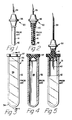
- Fig. 1 is a side elevation view representing a known blood collection needle assembly;
- Fig. 2 is a partial cross-sectional view of the needle assembly of Fig. 1 illustrating the second cannula and the internal structure of the resilient sleeve;
- Fig. 3 is a side elevation view of a known and used evacuated blood collection tube;
- Fig. 4 is a cross-sectional view of the evacuated tube of Fig. 3 taken along line 4-4;
- Fig. 5 is a partial cross-sectional view illustrating the interaction between the needle assembly of Fig. 1 and the evacuated tube of Fig. 3 when the second cannula of the needle assembly pierces the stopper of the evacuated tube;
- Fig. 6 is a perspective view of a device for separation of plasma from a blood sample by means of which the inner structure of a preferred embodiment of the invention is explained in detail;
- Fig. 7 is a top plan view of the device of Fig. 6;
- Fig. 8 is a side elevation view of the device of Fig. 6;
- Fig. 9 is a cross-sectional view of the device of Fig. 7 taken along line 9-9;
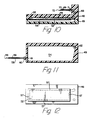
- Fig. 10 is a cross-sectional view of the device of Fig. 7 taken along line 10-10;
- Fig. 11 is a cross-sectional view of the device of Fig. 8 taken along line 11-11;
- Fig. 12 is a bottom plan view of the upper housing portion of the device of Fig. 6 illustrating the membrane separator attached to the upper housing portion;
- Fig. 13 is a bottom plan view of the upper housing portion of the device of Fig. 6, similar to the view of Fig. 12 but without the membrane separator;
- Fig. 14 is a cross-sectional view of the device of Fig. 8 taken along line 14-14;
- Fig. 15 is a top plan view of the device of Fig. 6 in use with evacuated tubes, taking a blood sample;
- Fig. 16 is a side elevation view of the device or Fig. 15, in use taking a blood sample;
- Fig. 17 is a partial cross-sectional view of the device of Fig. 15 taken substantially along line 17-17;
- Fig. 18 is a cross-sectional view of the device of Fig. 15 taken along line 18-18;
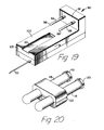
- Fig. 19 is a perspective view of the preferred embodiment of the device for separation of plasma from a blood sample whose inner structur is shown in Figures 6 to 18;
- Fig. 20 is a perspective view of a holding clap, with two evacuated tubes, for use with the device of Fig. 19;
- Fig. 21 is an end elevation view of the holding clamp of Fig. 20 illustrated without the evacuated tubes;
- Fig. 22 is an end elevation view of the holding clamp of Fig. 21 illustrated in an open position;
- Fig. 23 is a perspective view of another alternative embodiment of the preferred device for separation of plasma from a blood sample;
- Fig. 24 is a side elevation view of the device of Fig. 23 partially cross-sectioned to illustrate the structure surrounding the second needle cannula;
- Adverting to Figs. 1-5, known prior art blood collection devices include a
blood collection needle 30 and a blood collection evacuatedglass tube 31. The blood collection tube includes acylindrical glass body 32 withclosed end 34 and neck portion 35. The neck portion is sealed by a resilientpierceable stopper 37 which is applied to the tube while both components are in a reduced pressure environment so that theinterior portion 38 has an absolute internal pressure less than atmospheric pressure. - The blood collection needle includes a
hub 36, afirst cannula 39 adapted to pierce a patient's flesh and enter a blood containing vein therein.Second cannula 40 is adapted to piercestopper 37 to establish fluid communication between the patient's vein and the interior of the evacuated glass tube so that a blood sample is drawn from the patient into the tube. The first cannula and second cannula of the blood collection needle may be separate cannulas in fluid communication with each other through the hub or they may be part of one cannula which passes through the hub. Some blood collection needles include a resilient sleeve which prevents blood from leaving the blood collection needle after venipuncture. Aresilient sleeve 41 includes aclosed end 42 which is adapted to be pierced bysecond cannula 40 upon the application of external force to the sleeve in the direction along longitudinal axis ofcannula 40. This force can be applied by forcing the blood collection tube stopper onto the second cannula, as best illustrated in Fig. 5. After the blood sample is taken, the evacuated tube is removed from the blood collection needle and the resilient sleeve returns to its original position which allows it to prevent further blood from leaving the blood collection needle. It can be seen that this type of needle assembly will allow several tube samples to be taken from the same venipuncture because the second cannula is sealed after each tube is removed therefrom. Blood collection needle hubs commonly have external threads (not shown) to interact with a tube holder (not shown) to facilitate guiding the tube toward the second cannula so that the cannula pierces the central, thinner, portion of the stopper. - The blood sample, in the evacuated tube, may be placed in a centrifuge (not shown) and spun until the more dense cellular component of the blood sample is driven to the closed end portion of the tube and the less dense plasma is positioned above the cellular component closer to the neck portion. The stopper from the tube may then be removed and the plasma poured off for subsequent testing. Also, serum may be obtained by allowing the blood sample to coagulate before centrifuging the blood sample. The serum or plasma produced is used in various types of blood testing equipment which analyze the contents thereof to provide data with respect to the state of the patient's blood.
- In Figs. 6-14 the construction of the housing of the
preferred device 90 for separation of plasma from a blood sample (Fig. 19) for use with two evacuated receptacles, such as the blood collection evacuated glass tubes hereinabove described, is shown. Thehousing 47 comprisingupper housing portion 48 andlower housing portion 49 joined alongline 50 to form aninterior cavity 51. The housing of Figs. 6-18 is provided with co-ordinating means, as described in detail in Fig. 19, for cooperation with a holding means for the receptacles, as is described in Figs 20-22. - A
membrane separator 52 dividesinterior cavity 51 into a firstblood receiving portion 54 and a secondplasma receiving portion 55.Membrane separator 52 is attached toupper housing portion 48 along sealingarea 57 of the upper housing portion, via heat sealing, ultrasonic welding, solvent adhesive or other suitable means, so that fluid passing fromblood receiving portion 54 toplasma receiving portion 55 must pass throughmembrane separator 52. It will be apparent to one skilled in the art that there are numerous constructions which will allow the separation of housing portions by a membrane, for example, clamping the membrane between the housing portions, and that the structure recited hereinabove is exemplary of these many possibilities. - An
injection cannula 58 having alumen 59 therethrough is attached to ahollow hub portion 60 of the lower housing portion via adhesive or other suitable means.Lower housing portion 49 also includes an inlet conduit 6; providing fluid communication betweenlumen 59 andblood receiving portion 54. The injection cannula includes a sharpeneddistal tip 66 adapted to pierce the subject's flesh and enter a vein therein to provide the blood sample. It is within the purview of the present invention to include a structure wherein the injection cannula is separated from the housing portion by a length of flexible tubing so that the housing portion need not be positioned at the injection site but may be conveniently placed closely thereto. Ablood communication conduit 62 communicates betweenblood receiving portion 54 andupper housing portion 48. The blood communication conduit is opposed frominlet conduit 61 so that blood passing from the inlet conduit to the blood communicating conduit travels in a direction along the length ofmembrane separator 52 to establish a cross-flow relationship between the blood and the membrane. Afirst needle cannula 63 is mounted in the upper housing portion athub 64 via adhesive or other suitable means.Cannula 63 includeslumen 65 which is in fluid communication withblood communication conduit 62.First needle cannula 63 also includes sharpenedtip 67 adapted to pierce the stopper of an evacuated blood collection tube. - A
second needle cannula 69 having alumen 70 therethrough is attached to asecond hub portion 71 of the upper housing portion via adhesive or other suitable means. The second needle cannula includes a sharpenedtip 72 adapted to pierce the stopper of an evacuated blood collection tube. Theupper housing portion 48 also includes aplasma communication conduit 68 which allows fluid communication between the lumen of thesecond needle cannula 69 andplasma receiving portion 55 of the housing. - In order to support
membrane 52 when vacuum forces are applied, as will be explained in more detail hereinafter,support ribs 74 are provided inplasma receiving portion 55 of the upper housing. In the preferred embodiment these ribs are arranged in a parallel arrangement withrecesses 75 adjacent to the support ribs for allowing the flow of plasma from the membrane toplasma communication conduit 68. In the preferred embodiment the ribs are formed integrally with the upper housing portion. It is within the purview of the present invention to include other structures to support the membrane against the vacuum forces. These other structures include, but are not limited to: a separate panel, having raised surfaces, inserted in the upper housing portion; a structural screen supporting the membrane; and structural material laminated to the membrane and heat sealed to the housing portion. - Figs. 15-18 depict the device for the separation of plasma from a blood sample in use. Initially,
injection cannula 58 is inserted through the skin S of a mammalian body M so thatlumen 59 thereof is in fluid communication with the blood B in vein V. Immediately after the fluid communication with the vein is established, a rigid evacuatedblood collection tube 77 having apierceable stopper 78 is guided alongupper housing portion 48 so that firsk needle cannula piercesstopper 78 so that there is fluid communication betweeninterior 79 of the blood collection tube and the lumen ofcannula 63. Simultaneously, a rigid evacuatedcollection tube 80 is guided alongupper housing portion 48 so thatsecond needle cannula 69 pierces astopper 81 of the evacuated collection tube and there is fluid communication betweeninterior 82 and the lumen ofcannula 69. - It should be noted that it is desirable that evacuated
blood collection tube 77 and evacuatedblood collection tube 80 should be guided onto the device substantially simultaneously so that fluid communication between the respective cannulas and tubes is substantially simultaneous. When using a membrane having large pores, the simultaneous connection of the tubes avoids the possibility that one tube, inserted without the other, will lose a small portion of its vacuum force by drawing some environmental air through the membrane before the blood covers the membrane. This potential problem can also be avoided by pre-wetting the membrane with glycerol, saline solution or the like. - With the evacuated tubes connected to the device, as best illustrated in Figs. 17 and 18, evacuated
blood collection tube 77 creates a vacuum force within the housing which draws blood from vein V throughlumen 59 ofcannula 58, throughblood receiving portion 54 along the surface ofmembrane 52 and, finally, throughblood communicating conduit 62,lumen 65 ofneedle cannula 63 and into theblood collection tube 77. At the same time that theblood collection tube 77 is drawing blood through the device, evacuatedcollection tube 80 is providing a vacuum force on the side ofmembrane 52 opposite from the blood supply. The vacuum force created bycollection tube 80 causes plasma from the stream of blood flowing throughblood receiving portion 54 to cross throughmembrane 52 intoplasma receiving portion 55 of the housing. The plasma is guided along the housing bysupport ribs 74, throughplasma communication conduit 68 and the lumen ofsecond needle cannula 69 intocollection tube 80. - When the pressure inside the collection tubes is approximately equal to the blood pressure of the subject, evacuated
collection tube 80 will contain a quantity of plasma, separated from the blood, ready for use. Further,blood collection tube 77 will contain a quantity of blood, still containing plasma, which may be held aside pending the outcome of the analysis of the plasma fromtube 80. An advantage of the present invention is that it produces samples in two separate tubes. Accordingly, each tube can be sent to a different physical area for storage and/or testing as opposed to separation processes where the plasma and the remaining portion of the blood are contained in the same tube. Also, an important feature of the instant invention is that it allows the use of two separate vacuum sources, thus allowing the use of a wide variety of evacuated tubes having various volumes and degrees of evacuation. This feature greatly increases the flexibility of the instant invention with respect to optimizing the efficiency of the separation process. For example, differential pressure across the membrane can be varied using evacuated tubes having different degrees of evacuation. This is an advantage over systems driven by a single source of vacuum or pressure. -
Membrane separator 52 is constructed so that it contains pores having a diameter selected so that plasma from a blood sample can flow through the membrane while the cellular components of the blood sample are too large to pass therethrough. It is desirable to use a membrane having a pore size within the range of between about 0.2 and 1.5 micrometers. It is preferred that the membrane has a pore size within the range of between about 0.4 and 0.6 micrometer - If additional plasma or serum is required, depending on the time element,
blood collection tube 77 may be spun, in a centrifuge, to provide this additional fluid. Accordingly, a blood collection tube containing anticoagulant may be chosen so that the blood sample does not clot and plasma may still be obtained. Also, a blood collection tube containing a separator gel may be used. This latter type of tube may be centrifuged immediately, causing the gel to move to a position between the cellular mass and the plasma, thus preserving the sample for later use. - In the preferred
device injection cannula 58,first needle cannula 63 andsecond needle cannula 69 can be chosen from the range of sizes of commercially available blood collection needles. It is preferred thatinjection cannula 58 be within the range of about 20 gauge to 22 gauge and have a length within the range of about 25 mm to 38 mm (one to 1.5 inches). The first and second needle cannula are preferably within the range of about 20 gauge to 22 gauge and having a length of about 16 mm (0.635 inches). - A wide range of membrane sizes can be used with the present invention, depending on the variables associated with the various other elements. With respect to plasma separation, a membrane having an area within the range of about 11 cm² to 32 cm² is desirable when using commercially available evacuated tubes. In the preferred embodiment the membrane separator is sized so that approximately 11 cm² of area is available for transfer of plasma from the
blood receiving portion 54 toplasma receiving portion 55. Also, it is desirable that the ratio of length to width be in the range of about 4/1 to 10/1. It should be noted that the volume of the empty space within the interior cavity of the housing, the inlet conduit, the blood communication conduit and the plasma communication conduit must be held to the lowest possible practical value to minimize the amount of air that will be drawn into the evacuated tubes in order to fill this empty space with blood or plasma. This air, when it enters the evacuated tubes, reduces the amount of vacuum force available for drawing and separating the blood sample. - Although the above device is described using a membrane suitable for separating plasma from whole blood, it is within the purview of the instant invention to include embodiments suitable for separating light and heavy components of other fluids, such as separating a liquid portion from a colloidal suspension or separating small molecular species from a blood sample. Accordingly, membranes such as known ultrafiltration membranes and known non-woven membranes having suitable pore ratings may be used as components of the instant invention for separating the light and heavy components of a liquid sample.
- In connection with the
housing 91 of thedevice 90 shown in Figs. 19-22 and functioning in a substantially similar manner as the device 45 (Figs. 6-18) hereinabove described, a preferred embodiment of the invention provided with holding means and coordinating means is explained in detail. Thehousing 91 includesinjection cannula 92, first needle cannula (not shown) covered by firstresilient sleeve 94, and second needle cannula (not shown) covered by secondresilient sleeve 95.Sleeve 94 includesclosed end 96 which is adapted to be pierced by the first injection cannula upon the application of external force to the sleeve in a direction along the cannula towardupright wall 97 of the housing to allow fluid passage through the first needle cannula.Sleeve 94 will return to its original position upon termination of the external force. Likewise, secondresilient sleeve 95 includes closed end 99 which is adapted to be pierced by the second needle cannula upon the application of an external force to the second resilient sleeve along the second needle cannula in a direction towardupright wall 97, thus allowing fluid passage through the second needle cannula. Second resilient sleeve will return to its original position upon termination of the external force. -
Housing 91 includesplanar surface 100 having dove-tail guide groove 101 formed therein. It should be noted that the first needle cannula and the second needle cannula are positioned in a substantially parallel relationship. Further, dove-tail groove 101 originates atend 103 of the housing and runs alongplanar surface 100 in a direction which is substantially parallel to the longitudinal axes of the first and second needle cannula. - Also included is holding
clamp 102 for releasably holding evacuatedtubes resilient stoppers Clamp 102 includesupper portion 104 andlower portion 105 joined at ahinge 107. The upper portion of the holding clamp includes locking pin 108 which is adapted to engageaperture 109 in the lower portion. Locking pin 108 engagesaperture 109 in a snap-fit locking arrangement so that force is required for disengagement. Upper portion includes circularly shapedrecesses 110 and 111 having a coordinated relationship with circularly shapedrecesses tubes recesses aperture 109, the tubes will be held in a parallel relationship, as best illustrated in Fig. 20. - Holding
clamp 102 also includes dove-tail guide projection 117 projecting outwardly frombottom surface 118 oflower portion 105. Dove-tail guide projection 117 is adapted to cooperatively engage dove-tail guide groove 101 and slide freely therein. In using the device the operator places evacuated tubes in holdingclamp 102 and closes the locking clamp so that the tubes are held therein. The operator then engages the dove-tail guide projection of holdingclamp 102 into the dove-tail guide groove 101 of the housing and slides the clamp toward the needle cannula but does not allow the cannula to pierce the stoppers of the evacuated tubes. At this point, the injection cannula is inserted into the subject to achieve venipuncture and the holding clamp is moved in a direction towardupright wall 97 of the housing to cause the needle cannula to pierceresilient sleeves resilient stoppers - It may be desirable to only form the dove-tail groove in an area near the first and second needle cannula and to provide an enlarged entrance means at the end of the groove furthest from the cannula, so that the dove-tail guide projection of the clamp may be engaged in the dove-tail groove at a point intermediate the ends of the planar surface rather than at the end thereof.
- The holding clamp allows the evacuated tubes to be clamped in a parallel relationship and guided toward the injection cannulas so that both resilient stoppers will be pierced by the respective cannula simultaneously. The device also provides resilient sleeves to prevent fluid from passing through the injection cannula. It should be noted that these features, are independent features and are not dependent on each other for function. Accordingly, it is within the purview of this invention to provide a device having a holding clamp with coordinating means and, optionally, resilient sleeves.
- Referring now to Figs. 23 and 24, another alternative embodiment of the present device functions in substantially the same manner as the above-described preferred embodiment. This embodiment includes
housing 124 havinginjection cannula 125,first needle cannula 127 andsecond needle cannula 128. This embodiment differs from previously described embodiments in thathousing 124 includes frusto-conically shapedrecesses recesses - It should be noted that there are many possible combinations for positioning the injection cannula and the first needle cannula and the second needle cannula, and that the embodiments described herein represent only a few of the many possibilities.
- The housing of the present invention may be constructed of a wide variety of materials such as metals, plastics and ceramics. Plastic materials are more desirable because of their ability to be molded into a wide variety of complex shapes and for compatibility with blood. Transparent thermoplastic materials are preferred so that the operability of the device can be observed through the housing walls. A wide variety of metals and plastics are suitable for the various cannula of the present invention, with medical grade stainless steel being preferred. The choice of material for the membrane separator will depend on the composition of the materials being separated and the sizes of the particles which should be effectively blocked from passing through the membrane. Commercially available dialyzing membranes and ultrafiltration membranes may be used. Representative of such membranes are polycarbonate and polyester membranes having a pore size of within the range of between about 0.2 and 1.5 micrometers as manufactured by Nucleopore Corporation of Pleasanton, California, U.S.A.
- First
resilient sleeve 94 and secondresilient sleeve 95 are preferably made of self-sealing elastomeric materials such as rubber and thermoplastic elastomers. Holdingclamp 102 can be made of a wide variety of rigid materials with thermoplastic materials such as polypropylene being preferred. The use of injection molded thermoplastic, such as polypropylene, allows a design which incorporateshinge 107 as an integral part of the upper and lower portions of the holding clamp. - Thus the present invention provides a simple, straightforward, reliable, easily fabricated device for the separation of the lighter fraction from the heavier fraction of a liquid sample which wild operate without the use of additional equipment such as centrifuges and pumps, to promptly produce an isolated quantity of the lighter fraction of the liquid sample. The present invention also provides greater flexibility in optimizing the efficiency of the separation process by allowing the use of two separate evacuated receptacles which may be varied as to size and degree of evacuation.
Claims (13)
- Operable device for the separation of the lighter fraction from the heavier fraction of a liquid sample, comprising
first and second evacuated rigid receptacles (77,80;115,116) including an open end;
a housing (47;91;124) having an interior cavity (51);
a separator membrane (52) dividing said cavity (51) into a first portion (54) and a second portion (55), said separator membrane (52) having a porosity selected for the desired separation thereacross;
inlet means (61) for providing fluid communication between said first portion (54) and the source of the liquid sample;
first communication means (62) for providing fluid communication between said first portion (54) and said first receptacle (77;115), said first communication means (62) being opposed from said inlet means (61) so that liquid passing from said inlet means (61) to said first communication means (62) travels in a direction along the surface of said membrane (62); and
second communication means (68) for providing fluid communication between said second portion (55) and said second receptacle (80;116),
characterized in that
each receptacle (77,80;115,116) includes a pierceable stopper (78,81;119,120) sealably closing said open end,
a holding means (102) is provided for holding the first evacuated receptacle (77;115) and the second evacuated receptacle (80; 116) in a fixed relationship with respect to each other,
a coordinating means (101,117) between said housing (91) and said holding means (102) is provided to facilitate the controlled movement of the evacuated receptacles (77,80;115,116) into engagement and fluid communication with said first communication means (62) and said second communication means (68), and,
when said inlet means (61) is in fluid communication with the source of the liquid sample and said first communication means (62) is in fluid communication with the first evacuated receptacle (77;115) and said second communication means (68) is in fluid communication with the second evacuated receptacle (80;116), the liquid sample flows through said inlet means (61) along said membrane (52) through said first communication means (62) into the first evacuated receptacle (77;1l5), simultaneously, the lighter fraction of the liquid being drawn through said membrane (52) and said second communication means (68) into the second evacuated receptacle (80;116). - Device according to claim 1, characterized in that said first communication means (62) includes a first needle cannula (63) and said second communication means (68) includes a second needle cannula (69), each needle cannula (63,69) having a lumen (65;70) therethrough for piercing said pierceable stopper (78;81;119,120) of said respective first and second evacuated receptacle (77;80;115,116) when said first and second receptacles (77,80;115,116) are moved towards said first and second needle cannulas (63,69).
- Device according to claim 2, characterized in that at least one of said needle cannulas (63,69;127, 128) is covered by a resilient sleeve (94;95) to prevent fluid passage therethrough, adapted to be pierced by said cannula (63,69;127, 128) upon the application of external force to said sleeve (94;95) in a direction along said cannula (63,69;127,128) thus allowing fluid passage therethrough, said sleeve (94;95) further adapted to return to its original position upon termination of the external force.
- Device according to any one of claims 1 to 3, characterized by guide means (129,130) for guiding said first evacuated receptacle (77;115) so that said first needle cannula (63;127) pierces the pierceable stopper (78:119) of the first evacuated receptacle (80;116) and for guiding said second evacuated receptacle (80;116) so that said second needle cannula (69;128) pierces the pierceable stopper (81;120) of said second evacuated receptacle (80;116).
- Device according to any one of claims 2 to 4, characterized in that said first needle cannula (63;127) and said second needle cannula (69;128) are positioned in a substantially parallel relationship.
- Device according to any one of claims 1 to 5, characterized in that said holding means (102) holds said receptacles (77,80;115,116) so that movement of said receptacles (77,80;115,116) toward said first and second needle cannulas (63,69;127, 128;137,138) causes fluid communication between said first communication means (62) and said first receptacle (77;115) and said second communication means (68) and said second receptacle (80;116) substantially simultaneously.
- Device according to any one of claims 1 to 6, characterized by support means (74) for supporting said membrane (52) against vacuum forces in said second portion (55).
- Device according to claim 7, characterized in that said support means includes a distributor panel in said second portion (55) adjacent to said membrane (52), said planel having a raised surface for supporting said membrane (52) and recesses adjacent to said raised portion for receiving the lighter fraction of the liquid passing through said membrane and allowing the lighter fraction to pass to said second communication means (62).
- Device according to claim 8, characterized in that said distributor panel is integral with said housing (47;91;124).
- Device according to any one of claims 1 to 9, characterized in that said membrane (52) has a pore size within the range of between about 0.2 and 1.5 micrometers.
- Device according to any one of claims 1 to 10, characterized in that said membrane (52) has a pore size within the range of between about 0.4 and 0.6 micrometer.
- Device according to any one of claims 1 to 11, characterized in that said membrane (52) is made of material selected from the group consisting of polycarbonate and polyester.
- Device according to any one of claims 1 to 12, characterized in that said inlet means (61) includes a third needle cannula (58;92;125) having a lumen (59) therethrough and a sharp distal end (66) adapted to pierce the source of the liquid sample to establish fluid communication therewith.
Applications Claiming Priority (2)
| Application Number | Priority Date | Filing Date | Title |
|---|---|---|---|
| US694717 | 1985-01-25 | ||
| US06/694,717 US4879098A (en) | 1985-01-25 | 1985-01-25 | Device for the separation of the lighter fraction from the heavier fraction of a liquid sample |
Publications (3)
| Publication Number | Publication Date |
|---|---|
| EP0189152A2 EP0189152A2 (en) | 1986-07-30 |
| EP0189152A3 EP0189152A3 (en) | 1987-09-30 |
| EP0189152B1 true EP0189152B1 (en) | 1991-10-16 |
Family
ID=24789991
Family Applications (1)
| Application Number | Title | Priority Date | Filing Date |
|---|---|---|---|
| EP86100618A Expired - Lifetime EP0189152B1 (en) | 1985-01-25 | 1986-01-18 | A device for the separation of the lighter fraction from the heavier fraction of a liquid sample |
Country Status (11)
| Country | Link |
|---|---|
| US (3) | US4879098A (en) |
| EP (1) | EP0189152B1 (en) |
| JP (1) | JPS61175566A (en) |
| AU (1) | AU574250B2 (en) |
| DE (1) | DE3681925D1 (en) |
| DK (1) | DK38186A (en) |
| ES (1) | ES8700950A1 (en) |
| MX (1) | MX173244B (en) |
| MY (1) | MY100366A (en) |
| NZ (1) | NZ214607A (en) |
| ZA (1) | ZA859750B (en) |
Families Citing this family (49)
| Publication number | Priority date | Publication date | Assignee | Title |
|---|---|---|---|---|
| GB8602003D0 (en) * | 1986-01-28 | 1986-03-05 | Lawton P G | Carbonisable fibre assembly |
| US5135719A (en) * | 1986-10-29 | 1992-08-04 | Biotrack, Inc. | Blood separation device comprising a filter and a capillary flow pathway exiting the filter |
| US4980297A (en) * | 1987-02-27 | 1990-12-25 | Becton, Dickinson And Company | Device for the membrane separation of the components of a liquid sample |
| US5024238A (en) * | 1989-01-10 | 1991-06-18 | Cancer Diagnostics, Inc. | Blood withdrawing apparatus and antigen testing method |
| CA1337167C (en) * | 1989-03-14 | 1995-10-03 | Eastman Kodak Company | Needle housing with retractable needle |
| US5297561A (en) * | 1989-06-15 | 1994-03-29 | Hulon Walter C | Blood collection tube assembly |
| US5137031A (en) * | 1989-09-18 | 1992-08-11 | La Mina Ltd. | Urine testing apparatus with urinary sediment device |
| AT397610B (en) * | 1990-06-01 | 1994-05-25 | Avl Verbrennungskraft Messtech | DEVICE FOR TAKING BODY LIQUIDS |
| US5097842A (en) * | 1990-07-23 | 1992-03-24 | Bonn Gina B | Device for withdrawing fluids |
| DK68991D0 (en) * | 1991-04-17 | 1991-04-17 | Novo Nordisk As | HEADER |
| US5178157A (en) * | 1992-01-14 | 1993-01-12 | Fanlo Ramon G | Phlebotomy device and method of use thereof |
| US5810398A (en) | 1992-10-02 | 1998-09-22 | Pall Corporation | Fluid delivery systems and methods and assemblies for making connections |
| US5393101A (en) * | 1992-10-02 | 1995-02-28 | Pall Corporation | Connector assembly |
| US5380289A (en) * | 1993-01-19 | 1995-01-10 | The Board Of Regents Of The University Of Oklahoma | Fluid collection device |
| JPH09504726A (en) * | 1994-08-25 | 1997-05-13 | バクスター、インターナショナル、インコーポレイテッド | Closed blood sampling device |
| IL112339A (en) * | 1995-01-13 | 1999-07-14 | Travenol Lab Israel Ltd | Blood sampling apparatus |
| AU4766896A (en) * | 1995-02-09 | 1996-08-27 | First Medical, Inc. | Peristaltic system and method for plasma separation |
| US5575796A (en) * | 1995-05-17 | 1996-11-19 | Utah Medical Products, Inc. | Umbilical cord cutter and sampler |
| US5687740A (en) * | 1995-06-29 | 1997-11-18 | Becton, Dickinson And Company | Needle holder assembly including sleeve of thermoplastic elastomer |
| US5642248A (en) * | 1995-08-31 | 1997-06-24 | Leviton Manufacturing Co | Electrical extension cord with built-in safety protection |
| US5569210A (en) * | 1995-11-06 | 1996-10-29 | Moen; Michael | Multiple draw syringe |
| US5837203A (en) * | 1996-04-09 | 1998-11-17 | Sievers Instruments, Inc. | Device to alternately supply a fluid to an analyzer |
| IL118497A (en) * | 1996-05-30 | 2002-08-14 | Travenol Lab Israel Ltd | Fluid sampling apparatus |
| JP3685283B2 (en) * | 1997-02-13 | 2005-08-17 | 富士写真フイルム株式会社 | Plasma collection tool |
| EP1716885A3 (en) | 1997-05-09 | 2006-11-15 | Pall Corporation | Connector assemblies, fluid systems, and methods for making a connection |
| US7400477B2 (en) | 1998-08-24 | 2008-07-15 | Leviton Manufacturing Co., Inc. | Method of distribution of a circuit interrupting device with reset lockout and reverse wiring protection |
| US6102871A (en) * | 1998-11-23 | 2000-08-15 | Coe; Rosemarie O. | Blood collection funnel |
| IL128709A (en) | 1999-02-24 | 2004-09-27 | Teva Medical Ltd | Fluid sampling apparatus |
| US7288195B2 (en) * | 1999-05-28 | 2007-10-30 | Bio/Data Corporation | Method and apparatus for directly sampling a fluid for microfiltration |
| US6398956B1 (en) * | 1999-05-28 | 2002-06-04 | Bio/Data Corporation | Method and apparatus for directly sampling a fluid for microfiltration |
| US6936473B2 (en) | 2000-01-05 | 2005-08-30 | Leisure, Inc. | Method of preparing a biological sample for quantification |
| EP1125591A1 (en) * | 2000-01-05 | 2001-08-22 | Maehata, Eisuke | Instrument and method for blood separation |
| IL134528A (en) | 2000-02-14 | 2005-05-17 | Teva Medical Ltd | Donor blood sampling system |
| DE10046173C2 (en) * | 2000-09-08 | 2003-04-03 | Inst Chemo Biosensorik | Device and method for separating undissolved components from biological liquids |
| US8747669B1 (en) | 2005-12-29 | 2014-06-10 | Spf Innovations, Llc | Method and apparatus for the filtration of biological samples |
| US7384549B2 (en) | 2005-12-29 | 2008-06-10 | Spf Innovations, Llc | Method and apparatus for the filtration of biological solutions |
| US20080017577A1 (en) * | 2006-07-21 | 2008-01-24 | Becton, Dickinson And Company | Membrane-based Double-layer Tube for Sample Collections |
| US8454059B2 (en) | 2010-09-13 | 2013-06-04 | Pall Corporation | Connector assemblies, fluid systems including connector assemblies, and procedures for making fluid connections |
| US9060724B2 (en) | 2012-05-30 | 2015-06-23 | Magnolia Medical Technologies, Inc. | Fluid diversion mechanism for bodily-fluid sampling |
| US9022951B2 (en) | 2012-05-30 | 2015-05-05 | Magnolia Medical Technologies, Inc. | Fluid diversion mechanism for bodily-fluid sampling |
| EP3318295B1 (en) | 2012-10-11 | 2021-04-14 | Magnolia Medical Technologies, Inc. | System for delivering a fluid to a patient with reduced contamination |
| CA2890830A1 (en) * | 2012-11-07 | 2014-05-15 | Canox4Drug S.P.A. | Method and kit for determination of free copper in serum |
| CN109171766A (en) | 2012-11-30 | 2019-01-11 | 木兰医药技术股份有限公司 | Body fluid barrier means and the method for completely cutting off body fluid using body fluid barrier means |
| US11234626B2 (en) | 2015-06-12 | 2022-02-01 | Magnolia Medical Technologies, Inc. | Devices and methods for syringe-based fluid transfer for bodily-fluid sampling |
| EP3469358A1 (en) * | 2016-06-09 | 2019-04-17 | Becton, Dickinson and Company | Biological fluid separation device |
| CN116250868A (en) | 2017-09-12 | 2023-06-13 | 木兰医药技术股份有限公司 | Fluid control device and method of using the same |
| US11419531B2 (en) | 2017-12-07 | 2022-08-23 | Magnolia Medical Technologies, Inc. | Fluid control devices and methods of using the same |
| EP3920801A1 (en) | 2019-02-08 | 2021-12-15 | Magnolia Medical Technologies, Inc. | Devices and methods for bodily fluid collection and distribution |
| CN113784793B (en) | 2019-03-11 | 2023-09-19 | 木兰医药技术股份有限公司 | Fluid control device and method of using the same |
Family Cites Families (17)
| Publication number | Priority date | Publication date | Assignee | Title |
|---|---|---|---|---|
| US2595462A (en) * | 1950-08-05 | 1952-05-06 | Anna B Johnson | Sanitary and safe baby teething device |
| US3211645A (en) * | 1962-07-17 | 1965-10-12 | Technicon Instr | Method and apparatus for filtering sanguineous liquid streams |
| US3494351A (en) * | 1966-06-21 | 1970-02-10 | Ferrell S Horn | Multiple vial fluid collecting device |
| US3469572A (en) * | 1966-08-18 | 1969-09-30 | Becton Dickinson Co | Apparatus for taking multiple fluid samples |
| US3604410A (en) * | 1968-09-11 | 1971-09-14 | Gary L Whitacre | Multitube blood sampler |
| US3640388A (en) * | 1970-08-20 | 1972-02-08 | Damon Corp | Dialyzing liquid-collecting container |
| US3705100A (en) * | 1970-08-25 | 1972-12-05 | Amicon Corp | Blood fractionating process and apparatus for carrying out same |
| US3687296A (en) * | 1971-03-26 | 1972-08-29 | Ewi Research & Dev Corp | Fluid separator |
| US4057499A (en) * | 1973-03-09 | 1977-11-08 | Buono Frank S | Apparatus and method for separation of blood |
| US4140108A (en) * | 1977-08-10 | 1979-02-20 | Becton, Dickinson And Company | Blood collection assembly |
| US4191182A (en) * | 1977-09-23 | 1980-03-04 | Hemotherapy Inc. | Method and apparatus for continuous plasmaphersis |
| US4212742A (en) * | 1978-05-25 | 1980-07-15 | United States Of America | Filtration apparatus for separating blood cell-containing liquid suspensions |
| US4343705A (en) * | 1980-10-31 | 1982-08-10 | Instrumentation Laboratory | Biological liquid fractionation using alternate opposite flow directions across a membrane |
| FR2511872A1 (en) * | 1981-08-25 | 1983-03-04 | Messier Denis | Sepn. of plasma from blood - using self-contained vacuum canister with semipermeable membrane |
| US4526756A (en) * | 1982-05-10 | 1985-07-02 | Evergreen Industries, Inc. | Device for interconnecting specimen collecting tubes |
| CH663722A5 (en) * | 1982-11-26 | 1988-01-15 | Sartorius Gmbh | FILTRATION DEVICE. |
| US4639316A (en) * | 1984-12-14 | 1987-01-27 | Becton, Dickinson And Company | Automatic liquid component separator |
-
1985
- 1985-01-25 US US06/694,717 patent/US4879098A/en not_active Expired - Fee Related
- 1985-12-16 AU AU51299/85A patent/AU574250B2/en not_active Ceased
- 1985-12-18 NZ NZ214607A patent/NZ214607A/en unknown
- 1985-12-20 ZA ZA859750A patent/ZA859750B/en unknown
-
1986
- 1986-01-09 MX MX001193A patent/MX173244B/en unknown
- 1986-01-18 EP EP86100618A patent/EP0189152B1/en not_active Expired - Lifetime
- 1986-01-18 DE DE8686100618T patent/DE3681925D1/en not_active Expired - Fee Related
- 1986-01-24 DK DK38186A patent/DK38186A/en not_active Application Discontinuation
- 1986-01-24 ES ES551197A patent/ES8700950A1/en not_active Expired
- 1986-01-24 JP JP61013626A patent/JPS61175566A/en active Granted
-
1987
- 1987-09-29 MY MYPI87002104A patent/MY100366A/en unknown
- 1987-10-27 US US07/113,577 patent/US4843017A/en not_active Expired - Fee Related
-
1989
- 1989-08-11 US US07/392,869 patent/US4970052A/en not_active Expired - Lifetime
Also Published As
| Publication number | Publication date |
|---|---|
| MY100366A (en) | 1990-08-28 |
| DK38186A (en) | 1986-07-26 |
| DE3681925D1 (en) | 1991-11-21 |
| US4879098A (en) | 1989-11-07 |
| ZA859750B (en) | 1986-08-27 |
| MX173244B (en) | 1994-02-11 |
| NZ214607A (en) | 1988-05-30 |
| US4843017A (en) | 1989-06-27 |
| US4970052A (en) | 1990-11-13 |
| EP0189152A3 (en) | 1987-09-30 |
| JPS61175566A (en) | 1986-08-07 |
| EP0189152A2 (en) | 1986-07-30 |
| DK38186D0 (en) | 1986-01-24 |
| ES551197A0 (en) | 1986-11-16 |
| ES8700950A1 (en) | 1986-11-16 |
| AU5129985A (en) | 1986-07-31 |
| AU574250B2 (en) | 1988-06-30 |
| JPH0455264B2 (en) | 1992-09-02 |
Similar Documents
| Publication | Publication Date | Title |
|---|---|---|
| EP0189152B1 (en) | A device for the separation of the lighter fraction from the heavier fraction of a liquid sample | |
| EP0283663B1 (en) | Blood separation system | |
| EP0184852B1 (en) | Automatic liquid component separator | |
| US4210623A (en) | Fluid collection apparatus | |
| US5354483A (en) | Double-ended tube for separating phases of blood | |
| EP2264453B1 (en) | Method for filtering blood | |
| US4187861A (en) | Blood sample handling apparatus and method | |
| US5271852A (en) | Centrifugal methods using a phase-separation tube | |
| US7780860B2 (en) | Apparatus and method for separating and concentrating fluids containing multiple components | |
| KR100193172B1 (en) | Biological liquid treatment system and treatment method | |
| US6471855B1 (en) | Cassette with integral separation device | |
| US4040959A (en) | Multi-purpose blood bag | |
| US5545339A (en) | Method for processing biological fluid and treating separated component | |
| US4086060A (en) | Disposable manipulative laboratory device for transferring biological fluids | |
| EP3383269B1 (en) | Apparatus for preparing blood fraction concentrate | |
| WO1994007415A1 (en) | Multichamber container for blood or other fluid samples | |
| JPH01151909A (en) | Separator for cell-containing liquid | |
| US11344880B2 (en) | Centrifuge tube separation system, and methods of use | |
| GB2048097A (en) | Fluid Filtration and Collection Apparatus | |
| JPS6156766B2 (en) |
Legal Events
| Date | Code | Title | Description |
|---|---|---|---|
| PUAI | Public reference made under article 153(3) epc to a published international application that has entered the european phase |
Free format text: ORIGINAL CODE: 0009012 |
|
| AK | Designated contracting states |
Kind code of ref document: A2 Designated state(s): BE CH DE FR GB IT LI NL SE |
|
| PUAL | Search report despatched |
Free format text: ORIGINAL CODE: 0009013 |
|
| AK | Designated contracting states |
Kind code of ref document: A3 Designated state(s): BE CH DE FR GB IT LI NL SE |
|
| 17P | Request for examination filed |
Effective date: 19871023 |
|
| 17Q | First examination report despatched |
Effective date: 19890414 |
|
| GRAA | (expected) grant |
Free format text: ORIGINAL CODE: 0009210 |
|
| AK | Designated contracting states |
Kind code of ref document: B1 Designated state(s): BE CH DE FR GB IT LI NL SE |
|
| ITF | It: translation for a ep patent filed |
Owner name: ING. C. GREGORJ S.P.A. |
|
| REF | Corresponds to: |
Ref document number: 3681925 Country of ref document: DE Date of ref document: 19911121 |
|
| ET | Fr: translation filed | ||
| PLBE | No opposition filed within time limit |
Free format text: ORIGINAL CODE: 0009261 |
|
| STAA | Information on the status of an ep patent application or granted ep patent |
Free format text: STATUS: NO OPPOSITION FILED WITHIN TIME LIMIT |
|
| 26N | No opposition filed | ||
| EAL | Se: european patent in force in sweden |
Ref document number: 86100618.7 |
|
| PGFP | Annual fee paid to national office [announced via postgrant information from national office to epo] |
Ref country code: SE Payment date: 19980116 Year of fee payment: 13 |
|
| PGFP | Annual fee paid to national office [announced via postgrant information from national office to epo] |
Ref country code: CH Payment date: 19980122 Year of fee payment: 13 |
|
| PGFP | Annual fee paid to national office [announced via postgrant information from national office to epo] |
Ref country code: NL Payment date: 19980128 Year of fee payment: 13 |
|
| PGFP | Annual fee paid to national office [announced via postgrant information from national office to epo] |
Ref country code: BE Payment date: 19980320 Year of fee payment: 13 |
|
| PGFP | Annual fee paid to national office [announced via postgrant information from national office to epo] |
Ref country code: FR Payment date: 19990111 Year of fee payment: 14 |
|
| PG25 | Lapsed in a contracting state [announced via postgrant information from national office to epo] |
Ref country code: SE Free format text: LAPSE BECAUSE OF NON-PAYMENT OF DUE FEES Effective date: 19990119 |
|
| PGFP | Annual fee paid to national office [announced via postgrant information from national office to epo] |
Ref country code: GB Payment date: 19990121 Year of fee payment: 14 |
|
| PGFP | Annual fee paid to national office [announced via postgrant information from national office to epo] |
Ref country code: DE Payment date: 19990125 Year of fee payment: 14 |
|
| PG25 | Lapsed in a contracting state [announced via postgrant information from national office to epo] |
Ref country code: LI Free format text: LAPSE BECAUSE OF NON-PAYMENT OF DUE FEES Effective date: 19990131 Ref country code: CH Free format text: LAPSE BECAUSE OF NON-PAYMENT OF DUE FEES Effective date: 19990131 Ref country code: BE Free format text: LAPSE BECAUSE OF NON-PAYMENT OF DUE FEES Effective date: 19990131 |
|
| BERE | Be: lapsed |
Owner name: BECTON DICKINSON AND CY Effective date: 19990131 |
|
| PG25 | Lapsed in a contracting state [announced via postgrant information from national office to epo] |
Ref country code: NL Free format text: LAPSE BECAUSE OF NON-PAYMENT OF DUE FEES Effective date: 19990801 |
|
| REG | Reference to a national code |
Ref country code: CH Ref legal event code: PL |
|
| PG25 | Lapsed in a contracting state [announced via postgrant information from national office to epo] |
Ref country code: GB Free format text: LAPSE BECAUSE OF NON-PAYMENT OF DUE FEES Effective date: 20000118 |
|
| GBPC | Gb: european patent ceased through non-payment of renewal fee |
Effective date: 20000118 |
|
| PG25 | Lapsed in a contracting state [announced via postgrant information from national office to epo] |
Ref country code: FR Free format text: LAPSE BECAUSE OF NON-PAYMENT OF DUE FEES Effective date: 20000929 |
|
| PG25 | Lapsed in a contracting state [announced via postgrant information from national office to epo] |
Ref country code: DE Free format text: LAPSE BECAUSE OF NON-PAYMENT OF DUE FEES Effective date: 20001101 |
|
| REG | Reference to a national code |
Ref country code: FR Ref legal event code: ST |
|
| PG25 | Lapsed in a contracting state [announced via postgrant information from national office to epo] |
Ref country code: IT Free format text: LAPSE BECAUSE OF NON-PAYMENT OF DUE FEES;WARNING: LAPSES OF ITALIAN PATENTS WITH EFFECTIVE DATE BEFORE 2007 MAY HAVE OCCURRED AT ANY TIME BEFORE 2007. THE CORRECT EFFECTIVE DATE MAY BE DIFFERENT FROM THE ONE RECORDED. Effective date: 20050118 |