EP0190939A2 - High frequency attenuation cable and harness - Google Patents
High frequency attenuation cable and harness Download PDFInfo
- Publication number
- EP0190939A2 EP0190939A2 EP86300836A EP86300836A EP0190939A2 EP 0190939 A2 EP0190939 A2 EP 0190939A2 EP 86300836 A EP86300836 A EP 86300836A EP 86300836 A EP86300836 A EP 86300836A EP 0190939 A2 EP0190939 A2 EP 0190939A2
- Authority
- EP
- European Patent Office
- Prior art keywords
- high frequency
- cable
- dielectric constant
- layer
- conductor
- Prior art date
- Legal status (The legal status is an assumption and is not a legal conclusion. Google has not performed a legal analysis and makes no representation as to the accuracy of the status listed.)
- Granted
Links
Images

Classifications
-
- H—ELECTRICITY
- H01—ELECTRIC ELEMENTS
- H01B—CABLES; CONDUCTORS; INSULATORS; SELECTION OF MATERIALS FOR THEIR CONDUCTIVE, INSULATING OR DIELECTRIC PROPERTIES
- H01B11/00—Communication cables or conductors
- H01B11/02—Cables with twisted pairs or quads
- H01B11/06—Cables with twisted pairs or quads with means for reducing effects of electromagnetic or electrostatic disturbances, e.g. screens
-
- H—ELECTRICITY
- H01—ELECTRIC ELEMENTS
- H01B—CABLES; CONDUCTORS; INSULATORS; SELECTION OF MATERIALS FOR THEIR CONDUCTIVE, INSULATING OR DIELECTRIC PROPERTIES
- H01B11/00—Communication cables or conductors
- H01B11/02—Cables with twisted pairs or quads
- H01B11/12—Arrangements for exhibiting specific transmission characteristics
- H01B11/14—Continuously inductively loaded cables, e.g. Krarup cables
- H01B11/146—Continuously inductively loaded cables, e.g. Krarup cables using magnetically loaded coatings
Definitions
- This invention relates to a high frequency attenuation cable and to a high frequency attenuation cable harness.
- High frequency attenuation cables are well known.
- such cables include an absorption medium which filters out high frequency energy which could otherwise interfere with the operation of the cable.
- the effectiveness with which the high frequency energy is filtered out is referred to as the high frequency attenuation. The greater the attenuation, the higher the effectiveness.
- One aspect of this invention comprises a high frequency attenuation cable comprising a core comprising at least one conductor, each said conductor being surrounded by a layer of high dielectric constant material having a dielectric constant greater than about 4 when measured at 10 MHz and a volume resistivity of at least about 10 13 ohm-cm; and a layer of high frequency absorption medium.
- the high dielectric constant material preferably also has a tensile strength of at least about 4,000 pounds per square inch (psi). Additional layers of the absorption medium and/or the high dielectric material and/or a second dielectric material may also be present.
- the core is that portion of the cable which is surrounded by the electrically conductive shield and any outer or protective jacketing.
- the cable comprises a core which, in turn, comprises conductor 4, a layer of high frequency absorption medium 6 surrounding the conductor, and a layer of high dielectric constant material 8 surrounding the high frequency absorption medium.
- the cable may further comprise additional layers of absorption medium, high dielectric constant material, a second dielectric material and the like. Further the cable generally also is provided with an electrically conductive shield and a protective outer jacket.
- a layer of high dielectric constant material markedly increases the high frequency attenuation of the cable in the frequency range of 10 to 100 MHz.
- high dielectric constant material is used herein to mean a material has a dielectric constant (e) greater than about 4 when measured at 10 MHz. Further, the material has a volume resistivity of at least about 10 13 ohm-cm. The high dielectric constant material preferably also has a tensile strength greater than about 4,000 psi.
- a preferred high dielectric constant material is polyvinylidene fluoride.
- polyvinylidene fluoride is used herein to mean polymers of vinylidene fluoride. The homopolymer is preferred. Polyvinylidene fluoride is commercially available under the trademark Kynar from Pennwalt Corporation, Philadelphia, PA.
- TEFZEL is a copolymer of ethylene and tetrafluoroethylene and is a product of E.I. duPont de Nemours, Wilmington, DE.
- TEFZEL is a copolymer of ethylene and tetrafluoroethylene and is a product of E.I. duPont de Nemours, Wilmington, DE.
- Both polyethylene and TEFZEL are materials having low dielectric constants (e of about 2-3).
- prior art cables exhibit lower high frequency attenuation in the frequency range of 10-100 MHz than is desirable for certain uses.
- the high frequency absorption medium such as the well-known lossy materials disclosed in the Cornelius et al. references serves to allow the passage of low frequency energy but absorbs the high frequency energy.
- Lossy materials are also disclosed in Mayer, USP 3,309,633 and USP 3,191,132 which are incorporated herein by reference.
- a preferred lossy material for the present invention is ferrite-loaded polymer, for example, ferrite-loaded VITON® A (VITON A is a copolymer of vinylidene fluoride and hexafluoropropylene and is a product of E. I. Du Pont de Nemours, Wilmington, DE).
- FIG. 2 there is disclosed a second embodiment of the invention.
- the cable comprises a conductor 4, a layer of high dielectric constant material 9 surrounding the conductor, a layer of high frequency absorption medium 6 surrounding the layer 9 of high dielectric constant material, and an additional layer of dielectric material 8 surrounding the layer of high frequency absorption medium.
- the dielectric material of the additional layer can be a high dielectric constant material, as defined herein, or a second dielectric material, e.g. one having a lower dielectric constant, e.g. below about 3.
- high frequency attenuation cable (not shown) comprises a conductor, a layer of high dielectric constant material surrounding the conductor, and a high frequency absorption medium surrounding the layer of high dielectric material. It is believed that this cable construction will also lead to improved high frequency attenuation in the 10 to 100 megahertz range, as was the case with the previous embodiments.
- the high dielectric material preferably polyvinylidene fluoride
- the high dielectric material can be located either inside of the high frequency absorption medium or outside of the high frequency absorption medium or both inside and outside of the high frequency absorption medium.
- a layer of dielectric material having a dielectric constant less than about 3 can be included in the construction, preferably as an outermost layer.
- the additional layer of dielectric material can be selected to provide desired electrical and/or mechanical properties.
- the additional layer should be of a high dielectric constant material, e.g. polyvinylidene fluoride.
- a material having a lower dielectric constant e.g. polyethylene or TEFZEL, can be used.
- the selection of the additional layer of dielectric material is made to provide good mechanical properties.
- Suitable dielectric materials under these criteria include polyethylene, polyvinyl chloride, TEFZEL, polyesters, polyamides, polyamide-imides, polyether-esters, and the like also polymeric blends.
- the high dielectric constant material and the second dielectric material, if present, can include various additives such as stabilizers, pigments, flame retardants, processing aids and the like.
- the cable constructions may further comprise an electrically conductive shielding means surrounding the core and an outer jacket surrounding the shielding means.
- a relatively thin layer of high dielectric constant material is used. While the reason for the improved performance is not fully understood, it is believed to be due to the increased capacitance between the absorptive material and the conductor when the high dielectric constant material is positioned therebetween or between the absorptive medium and the electrically conductive shield when the high dielectric material is positioned outside of the absorptive medium. The capacitance is further increased if the layer of the high dielectric constant material is relatively thin.
- each of the cable harnesses comprises a plurality-of cables with each cable having a core as described above.
- the core will comprise a conductor, a high frequency absorption medium surrounding the conductor and at least one layer of high dielectric constant material, preferably polyvinylidene fluoride.
- the only difference between the various cores will be the location of the high dielectric constant material which may be inside or outside, or both inside and outside of the high frequency absorption medium.
- Figure 3 illustrates one embodiment of a cable harness 20 having a plurality of cables 22 in which, in each core there is a conductor 24 surrounded by a high frequency absorption medium 26 which in turn is surrounded by a layer of high dielectric constant material 28.
- each cable 42 of cable harness 40 has a core having at least one conductor 44 surrounded by a high frequency absorption medium 46 which is in turn surrounded by a layer of high dielectric constant material 48.
- each cable comprises electrically conductive shielding means 30 surrounding each of the cores and an outer jacket 32 surrounding each of the electrically conductive shielding means.
- the construction in Figure 3 may further comprise protective outer jacketing 34 surrounding the plurality of cables.
- the cable harness 40 comprises gross electrically conductive shielding means 50 surrounding the plurality of cables and protective outer jacketing 52 surrounding the shielding means.
- the high frequency absorption medium may be any of the well-known lossy materials.
- the preferred lossy material is ferrite-loaded polymer and more preferably ferrite-loaded VITON.
- the cable construction having the KYNAR insulation layer (Sample 2) is far superior over the entire frequency range to the cable construction having the TEFZEL insulation layer (Sample 1). Most importantly, in the critical range of 10 to 100 MHz the attenuation has been dramatically improved.
- Sample 1 had KYNAR (high dielectric constant material) insulation and the other sample (Sample 2) had polyethylene (low dielectric constant material) insulation.
- Sample 2 had polyethylene (low dielectric constant material) insulation.
- the sample having the KYNAR is far superior over the entire frequency range to the sample having the polyethylene insulation.
- the critical range of 10 to 100 MHz the attenuation of the sample having KYNAR insulation is markedly improved over the sample having the polyethylene insulation.
- an insulation layer of high dielectric constant material preferably polyvinylidene fluoride (commercially available as KYNAR) that the attenuation of the cable construction in the frequency range of 10 to 100 MHz is surprisingly and unexpectedly improved over the prior art cable constructions using polyethylene, TEFZEL, or other similar insulation materials.
- KYNAR polyvinylidene fluoride
- a sample was prepared by extruding a first layer of polyvinylidene fluoride having a wall thickness of 3 mils onto a stranded, tin_plated 20 AWG copper conductor. Onto this was extruded a 4 mil layer of ferrite filled VITON A as described in Examples I and II.
- a third layer consisting of an ethylene tetrafluoroethylene copolymer (ETFE) with a wall thickness of 4 mils was then extruded on top of the first two layers. The sample was then surrounded with a metallic braid, and the insertion loss was measured. The results were as follows:
Abstract
Description
- This invention relates to a high frequency attenuation cable and to a high frequency attenuation cable harness.
- High frequency attenuation cables are well known. In general, such cables include an absorption medium which filters out high frequency energy which could otherwise interfere with the operation of the cable. The effectiveness with which the high frequency energy is filtered out is referred to as the high frequency attenuation. The greater the attenuation, the higher the effectiveness.
- Various attempts have been made to improve the high frequency attenuation of these cables. in this regard, see for example, Mayer, USP 4,301,428; Martin, USP 4,347,487; Cornelius et al., USP 4,486,721; and Cornelius et al., USP 4,499,438, all of which are incorporated herein by reference.
- These references generally disclose a cable construction in which a conductor is surrounded, in order, by a high frequency energy attenuation medium, a dielectric, and an electrically conductive shielding means. In the Cornelius et al. application, the relative positions of the high frequency energy attenuation medium and the dielectric are reversed.
- While the high frequency attenuation cables described in the above references have improved high frequency attenuation above 100 megahertz (MHz), the attenuation in the range of 10 to 100 MHz is somewhat less than that desired for certain applications. This invention provides a high frequency attenuation cable having improved high frequency attenuation in the 10-100 MHz range.
- r One aspect of this invention comprises a high frequency attenuation cable comprising a core comprising at least one conductor, each said conductor being surrounded by a layer of high dielectric constant material having a dielectric constant greater than about 4 when measured at 10 MHz and a volume resistivity of at least about 1013 ohm-cm; and a layer of high frequency absorption medium. The high dielectric constant material preferably also has a tensile strength of at least about 4,000 pounds per square inch (psi). Additional layers of the absorption medium and/or the high dielectric material and/or a second dielectric material may also be present.
- It should be understood that the core is that portion of the cable which is surrounded by the electrically conductive shield and any outer or protective jacketing.
- I have discovered that the use of a high dielectric constant material surprisingly and unexpectedly improves the high frequency attenuation in the frequency range of 10 to 100 MHz.
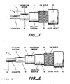
- Figure 1 is a cut-away side view of one embodiment of a cable construction according to the invention.
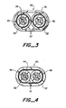
- Figure 2 is a cut-away side view of another embodiment of a cable construction according to the invention.
- Figure 3 is a cross-sectional view of one embodiment of a cable harness according to the invention.
- Figure 4 is a cross-sectional view of another embodiment of a cable harness according to the invention.
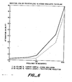
- Figures 5 and 6 are graphs of attenuation versus . frequency for cable constructions according to the invention compared to cable constructions according to the prior art.
- Referring to the figures in more detail, and particularly referring to Figure 1, there is disclosed a high
frequency attenuation cable 2. The cable comprises a core which, in turn, comprisesconductor 4, a layer of highfrequency absorption medium 6 surrounding the conductor, and a layer of high dielectricconstant material 8 surrounding the high frequency absorption medium. - It is to be understood that the cable may further comprise additional layers of absorption medium, high dielectric constant material, a second dielectric material and the like. Further the cable generally also is provided with an electrically conductive shield and a protective outer jacket.
- As will become more apparent hereafter, the use of a layer of high dielectric constant material according to the invention markedly increases the high frequency attenuation of the cable in the frequency range of 10 to 100 MHz.
- The term "high dielectric constant material" is used herein to mean a material has a dielectric constant (e) greater than about 4 when measured at 10 MHz. Further, the material has a volume resistivity of at least about 1013 ohm-cm. The high dielectric constant material preferably also has a tensile strength greater than about 4,000 psi. A preferred high dielectric constant material is polyvinylidene fluoride. The term polyvinylidene fluoride is used herein to mean polymers of vinylidene fluoride. The homopolymer is preferred. Polyvinylidene fluoride is commercially available under the trademark Kynar from Pennwalt Corporation, Philadelphia, PA.
- In typical prior art high frequency attenuation cable construction there generally is a conductor surrounded by a high frequency absorption medium which is in turn surrounded by a dielectric material such as polyethylene or TEFZELO (TEFZEL is a copolymer of ethylene and tetrafluoroethylene and is a product of E.I. duPont de Nemours, Wilmington, DE). Both polyethylene and TEFZEL are materials having low dielectric constants (e of about 2-3). As mentioned above prior art cables exhibit lower high frequency attenuation in the frequency range of 10-100 MHz than is desirable for certain uses.
- The high frequency absorption medium such as the well-known lossy materials disclosed in the Cornelius et al. references serves to allow the passage of low frequency energy but absorbs the high frequency energy. Lossy materials are also disclosed in Mayer, USP 3,309,633 and USP 3,191,132 which are incorporated herein by reference. A preferred lossy material for the present invention is ferrite-loaded polymer, for example, ferrite-loaded VITON® A (VITON A is a copolymer of vinylidene fluoride and hexafluoropropylene and is a product of E. I. Du Pont de Nemours, Wilmington, DE).
- In Figure 2 there is disclosed a second embodiment of the invention. As shown in the figure, there is a high frequency attenuation cable 2'. The cable comprises a
conductor 4, a layer of high dielectricconstant material 9 surrounding the conductor, a layer of highfrequency absorption medium 6 surrounding thelayer 9 of high dielectric constant material, and an additional layer ofdielectric material 8 surrounding the layer of high frequency absorption medium. The dielectric material of the additional layer can be a high dielectric constant material, as defined herein, or a second dielectric material, e.g. one having a lower dielectric constant, e.g. below about 3.- - It has been found that when high dielectric constant material is located both inside and outside of the high frequency absorption medium that similar results are obtained as when a layer of high dielectric constant material having a thickness equal to the total thickness of the two layers is located only outside of the absorption medium.
- Another embodiment of the high frequency attenuation cable (not shown) comprises a conductor, a layer of high dielectric constant material surrounding the conductor, and a high frequency absorption medium surrounding the layer of high dielectric material. It is believed that this cable construction will also lead to improved high frequency attenuation in the 10 to 100 megahertz range, as was the case with the previous embodiments.
- Thus, it is now apparent that the high dielectric material, preferably polyvinylidene fluoride, can be located either inside of the high frequency absorption medium or outside of the high frequency absorption medium or both inside and outside of the high frequency absorption medium. Further, a layer of dielectric material having a dielectric constant less than about 3 can be included in the construction, preferably as an outermost layer.
- The additional layer of dielectric material can be selected to provide desired electrical and/or mechanical properties. For example, for maximum attenuation, it is believed that the additional layer should be of a high dielectric constant material, e.g. polyvinylidene fluoride. In certain situations it may be desirable to optimize the overall capacitance of the cable making it as low as possible while still maintaining good attenuation. In such a situation a material having a lower dielectric constant, e.g. polyethylene or TEFZEL, can be used. In other instances the selection of the additional layer of dielectric material is made to provide good mechanical properties. For example good solvent resistance, toughness, abrasion resistance, cut through resistance and the like may lead to the selection of a particular dielectric material even if optimum electrical performance is not achieved. Suitable dielectric materials under these criteria include polyethylene, polyvinyl chloride, TEFZEL, polyesters, polyamides, polyamide-imides, polyether-esters, and the like also polymeric blends. The high dielectric constant material and the second dielectric material, if present, can include various additives such as stabilizers, pigments, flame retardants, processing aids and the like.
- The cable constructions may further comprise an electrically conductive shielding means surrounding the core and an outer jacket surrounding the shielding means.
- It has been found that the use of a high dielectric constant material, as defined above, leads to significantly improved performance. It has also been found that reducing the wall thickness of the high dielectric constant material will also lead to enhanced performance. Thus, in a pre- .ferred embodiment of this invention, a relatively thin layer of high dielectric constant material is used. While the reason for the improved performance is not fully understood, it is believed to be due to the increased capacitance between the absorptive material and the conductor when the high dielectric constant material is positioned therebetween or between the absorptive medium and the electrically conductive shield when the high dielectric material is positioned outside of the absorptive medium. The capacitance is further increased if the layer of the high dielectric constant material is relatively thin.
- Further disclosed according to the invention, as illustrated in Figures 3 and 4, are high frequency attenuation cable harnesses. Each of the cable harnesses comprises a plurality-of cables with each cable having a core as described above. Thus, in general the core will comprise a conductor, a high frequency absorption medium surrounding the conductor and at least one layer of high dielectric constant material, preferably polyvinylidene fluoride. The only difference between the various cores will be the location of the high dielectric constant material which may be inside or outside, or both inside and outside of the high frequency absorption medium.
- Figure 3 illustrates one embodiment of a
cable harness 20 having a plurality ofcables 22 in which, in each core there is aconductor 24 surrounded by a highfrequency absorption medium 26 which in turn is surrounded by a layer of high dielectricconstant material 28. - - Similarly, in Figure 4, each
cable 42 ofcable harness 40 has a core having at least oneconductor 44 surrounded by a highfrequency absorption medium 46 which is in turn surrounded by a layer of high dielectricconstant material 48. - The main distinguishing feature between the constructions in Figures 3 and 4 is how the individual cables are shielded. Thus, in Figure 3 each cable comprises electrically conductive shielding means 30 surrounding each of the cores and an
outer jacket 32 surrounding each of the electrically conductive shielding means. The construction in Figure 3 may further comprise protectiveouter jacketing 34 surrounding the plurality of cables. - Returning to Figure 4, the
cable harness 40 comprises gross electrically conductive shielding means 50 surrounding the plurality of cables and protectiveouter jacketing 52 surrounding the shielding means. - As stated above, the high frequency absorption medium may be any of the well-known lossy materials. However the preferred lossy material is ferrite-loaded polymer and more preferably ferrite-loaded VITON.
- The advantages of the invention will become more apparent after reference to the following examples.
- Two samples were prepared each by extruding a first layer (about 15 mils thick) of high frequency absorption medium (about 5 mils thick) onto a stranded
conductor 40 mils in diameter and then a second layer (about 5 mils thick) of dielectric material. Each core was surrounded by metallic braid for shielding and then surrounded by outer jacketing. The only difference between the samples was that in one sample the dielectric material was TEFZEL (low dielectric constant material) and in the other sample the insulation layer was KYNAR, polyvinylidene fluoride (high dielectric constant material). Each sample was surrounded by a metallic braid and the insertion loss was measured. The results are illustrated in Figure 5. - As can be seen, the cable construction having the KYNAR insulation layer (Sample 2) is far superior over the entire frequency range to the cable construction having the TEFZEL insulation layer (Sample 1). Most importantly, in the critical range of 10 to 100 MHz the attenuation has been dramatically improved.
- Two other samples were similarly prepared. Both of the samples in general had a conductor surrounded by a layer of lossy material which in these samples consisted of 30 volume percent of ferrite in VITON. The cable constructions further comprised a layer of insulative dielectric material surrounded by electrically conductive shielding means and finally surrounded by outer jacketing. The results are illustrated in Figure 6.
- The only difference between the samples was that
Sample 1 had KYNAR (high dielectric constant material) insulation and the other sample (Sample 2) had polyethylene (low dielectric constant material) insulation. As can be seen in Figure 6 the sample having the KYNAR is far superior over the entire frequency range to the sample having the polyethylene insulation. And again most importantly, in the critical range of 10 to 100 MHz, the attenuation of the sample having KYNAR insulation is markedly improved over the sample having the polyethylene insulation. - In view of the above results it can be appreciated that by using an insulation layer of high dielectric constant material, preferably polyvinylidene fluoride (commercially available as KYNAR) that the attenuation of the cable construction in the frequency range of 10 to 100 MHz is surprisingly and unexpectedly improved over the prior art cable constructions using polyethylene, TEFZEL, or other similar insulation materials.
- A sample was prepared by extruding a first layer of polyvinylidene fluoride having a wall thickness of 3 mils onto a stranded, tin_plated 20 AWG copper conductor. Onto this was extruded a 4 mil layer of ferrite filled VITON A as described in Examples I and II. A third layer consisting of an ethylene tetrafluoroethylene copolymer (ETFE) with a wall thickness of 4 mils was then extruded on top of the first two layers. The sample was then surrounded with a metallic braid, and the insertion loss was measured. The results were as follows:

- While the invention has been described herein in accordance with certain preferred embodiments thereof, many modifications and changes will be apparent to those skilled in the art. Accordingly, it is intended by the appended claims to cover all such modifications and changes as fall within the true spirit and scope of the invention.
Claims (17)
Priority Applications (1)
| Application Number | Priority Date | Filing Date | Title |
|---|---|---|---|
| AT86300836T ATE64795T1 (en) | 1985-02-06 | 1986-02-06 | HIGH FREQUENCY ATTENUATION CABLES AND BUNDLES. |
Applications Claiming Priority (2)
| Application Number | Priority Date | Filing Date | Title |
|---|---|---|---|
| US69864585A | 1985-02-06 | 1985-02-06 | |
| US698645 | 1985-02-06 |
Publications (3)
| Publication Number | Publication Date |
|---|---|
| EP0190939A2 true EP0190939A2 (en) | 1986-08-13 |
| EP0190939A3 EP0190939A3 (en) | 1988-08-17 |
| EP0190939B1 EP0190939B1 (en) | 1991-06-26 |
Family
ID=24806107
Family Applications (1)
| Application Number | Title | Priority Date | Filing Date |
|---|---|---|---|
| EP86300836A Expired - Lifetime EP0190939B1 (en) | 1985-02-06 | 1986-02-06 | High frequency attenuation cable and harness |
Country Status (9)
| Country | Link |
|---|---|
| EP (1) | EP0190939B1 (en) |
| JP (1) | JPS61198509A (en) |
| KR (1) | KR860006808A (en) |
| AT (1) | ATE64795T1 (en) |
| AU (1) | AU5323586A (en) |
| BR (1) | BR8600498A (en) |
| CA (1) | CA1255767A (en) |
| DE (1) | DE3679917D1 (en) |
| ES (1) | ES9200007A1 (en) |
Cited By (10)
| Publication number | Priority date | Publication date | Assignee | Title |
|---|---|---|---|---|
| EP0500203A1 (en) * | 1991-02-19 | 1992-08-26 | Champlain Cable Corporation | Shielded wire or cable |
| US5262591A (en) * | 1991-08-21 | 1993-11-16 | Champlain Cable Corporation | Inherently-shielded cable construction with a braided reinforcing and grounding layer |
| US5262592A (en) * | 1991-02-19 | 1993-11-16 | Champlain Cable Corporation | Filter line cable featuring conductive fiber shielding |
| WO1993024942A1 (en) * | 1992-06-01 | 1993-12-09 | Siemens Aktiengesellschaft | Electrical high-voltage switchgear with at least one sensor |
| US5313017A (en) * | 1991-08-21 | 1994-05-17 | Champlain Cable Corporation | High-temperature, light-weight filter line cable |
| EP0624885A1 (en) * | 1993-05-10 | 1994-11-17 | Alcatel Cable | Cable usable within the telecommunications field |
| US5545853A (en) * | 1993-07-19 | 1996-08-13 | Champlain Cable Corporation | Surge-protected cable |
| US6314182B1 (en) | 1998-08-19 | 2001-11-06 | 3M Innovative Properties Company | External filter box |
| CN108461190A (en) * | 2018-02-07 | 2018-08-28 | 上海传输线研究所(中国电子科技集团公司第二十三研究所) | A kind of filtering electric wire of resistance to complex electromagnetic environment |
| CN108986961A (en) * | 2018-07-11 | 2018-12-11 | 常州凌天达传输科技有限公司 | A kind of polyvinylidene fluoride diene insulation electromagnetism filtered electrical cable and processing method |
Families Citing this family (1)
| Publication number | Priority date | Publication date | Assignee | Title |
|---|---|---|---|---|
| GB2179196B (en) * | 1985-08-08 | 1989-01-11 | Pirelli General Plc | Electric cables |
Citations (2)
| Publication number | Priority date | Publication date | Assignee | Title |
|---|---|---|---|---|
| GB1134636A (en) * | 1964-11-26 | 1968-11-27 | Electronique Et D Automatique | Improvements in or relating to devices for the transmission of electrical energy |
| EP0081373A2 (en) * | 1981-12-07 | 1983-06-15 | RAYCHEM CORPORATION (a California corporation) | High frequency attenuation cable core |
-
1986
- 1986-02-05 AU AU53235/86A patent/AU5323586A/en not_active Abandoned
- 1986-02-05 BR BR8600498A patent/BR8600498A/en not_active IP Right Cessation
- 1986-02-06 CA CA000501216A patent/CA1255767A/en not_active Expired
- 1986-02-06 DE DE8686300836T patent/DE3679917D1/en not_active Expired - Fee Related
- 1986-02-06 EP EP86300836A patent/EP0190939B1/en not_active Expired - Lifetime
- 1986-02-06 JP JP61025657A patent/JPS61198509A/en active Pending
- 1986-02-06 KR KR1019860000814A patent/KR860006808A/en not_active Application Discontinuation
- 1986-02-06 AT AT86300836T patent/ATE64795T1/en active
- 1986-02-06 ES ES551709A patent/ES9200007A1/en not_active Expired
Patent Citations (2)
| Publication number | Priority date | Publication date | Assignee | Title |
|---|---|---|---|---|
| GB1134636A (en) * | 1964-11-26 | 1968-11-27 | Electronique Et D Automatique | Improvements in or relating to devices for the transmission of electrical energy |
| EP0081373A2 (en) * | 1981-12-07 | 1983-06-15 | RAYCHEM CORPORATION (a California corporation) | High frequency attenuation cable core |
Cited By (12)
| Publication number | Priority date | Publication date | Assignee | Title |
|---|---|---|---|---|
| EP0500203A1 (en) * | 1991-02-19 | 1992-08-26 | Champlain Cable Corporation | Shielded wire or cable |
| US5262592A (en) * | 1991-02-19 | 1993-11-16 | Champlain Cable Corporation | Filter line cable featuring conductive fiber shielding |
| US5262591A (en) * | 1991-08-21 | 1993-11-16 | Champlain Cable Corporation | Inherently-shielded cable construction with a braided reinforcing and grounding layer |
| US5313017A (en) * | 1991-08-21 | 1994-05-17 | Champlain Cable Corporation | High-temperature, light-weight filter line cable |
| WO1993024942A1 (en) * | 1992-06-01 | 1993-12-09 | Siemens Aktiengesellschaft | Electrical high-voltage switchgear with at least one sensor |
| EP0624885A1 (en) * | 1993-05-10 | 1994-11-17 | Alcatel Cable | Cable usable within the telecommunications field |
| FR2705161A1 (en) * | 1993-05-10 | 1994-11-18 | Alcatel Cable | Cable usable in the field of telecommunications. |
| US5530206A (en) * | 1993-05-10 | 1996-06-25 | Alcatel Cable | Telecommunication cable |
| US5545853A (en) * | 1993-07-19 | 1996-08-13 | Champlain Cable Corporation | Surge-protected cable |
| US6314182B1 (en) | 1998-08-19 | 2001-11-06 | 3M Innovative Properties Company | External filter box |
| CN108461190A (en) * | 2018-02-07 | 2018-08-28 | 上海传输线研究所(中国电子科技集团公司第二十三研究所) | A kind of filtering electric wire of resistance to complex electromagnetic environment |
| CN108986961A (en) * | 2018-07-11 | 2018-12-11 | 常州凌天达传输科技有限公司 | A kind of polyvinylidene fluoride diene insulation electromagnetism filtered electrical cable and processing method |
Also Published As
| Publication number | Publication date |
|---|---|
| CA1255767A (en) | 1989-06-13 |
| ES9200007A1 (en) | 1991-12-01 |
| JPS61198509A (en) | 1986-09-02 |
| BR8600498A (en) | 1986-10-21 |
| KR860006808A (en) | 1986-09-15 |
| EP0190939B1 (en) | 1991-06-26 |
| AU5323586A (en) | 1986-08-14 |
| EP0190939A3 (en) | 1988-08-17 |
| ATE64795T1 (en) | 1991-07-15 |
| DE3679917D1 (en) | 1991-08-01 |
Similar Documents
| Publication | Publication Date | Title |
|---|---|---|
| EP1335390B1 (en) | Communication cables with oppositely twinned and bunched insulated conductors | |
| US4376920A (en) | Shielded radio frequency transmission cable | |
| US6998537B2 (en) | Multi-pair data cable with configurable core filling and pair separation | |
| US6812408B2 (en) | Multi-pair data cable with configurable core filling and pair separation | |
| US5170010A (en) | Shielded wire and cable with insulation having high temperature and high conductivity | |
| EP0649561B1 (en) | Twisted pair data bus cable | |
| EP1331648B1 (en) | Electrical cable | |
| CA2702263C (en) | Waterproof data cable with foam filler and water blocking material | |
| US4649228A (en) | Transmission line | |
| EP0190939B1 (en) | High frequency attenuation cable and harness | |
| EP0161065B1 (en) | Electrical transmission line | |
| EP2432090A1 (en) | Cable with a split tube and method for making the same | |
| EP0961298B1 (en) | Electrical signal bundle | |
| CN213844842U (en) | Water-blocking cable | |
| WO2022209876A1 (en) | Coaxial cable | |
| EP0296692A2 (en) | A multi-conductor electrical cable of controlled electrical performance | |
| EP0540322A2 (en) | Foamed plastic insulated wires and coaxial cables using the same |
Legal Events
| Date | Code | Title | Description |
|---|---|---|---|
| PUAI | Public reference made under article 153(3) epc to a published international application that has entered the european phase |
Free format text: ORIGINAL CODE: 0009012 |
|
| 17P | Request for examination filed |
Effective date: 19860211 |
|
| AK | Designated contracting states |
Kind code of ref document: A2 Designated state(s): AT BE CH DE FR GB IT LI NL SE |
|
| RAP1 | Party data changed (applicant data changed or rights of an application transferred) |
Owner name: RAYCHEM CORPORATION (A DELAWARE CORPORATION) |
|
| PUAL | Search report despatched |
Free format text: ORIGINAL CODE: 0009013 |
|
| AK | Designated contracting states |
Kind code of ref document: A3 Designated state(s): AT BE CH DE FR GB IT LI NL SE |
|
| 17Q | First examination report despatched |
Effective date: 19900927 |
|
| GRAA | (expected) grant |
Free format text: ORIGINAL CODE: 0009210 |
|
| AK | Designated contracting states |
Kind code of ref document: B1 Designated state(s): AT BE CH DE FR GB IT LI NL SE |
|
| PG25 | Lapsed in a contracting state [announced via postgrant information from national office to epo] |
Ref country code: IT Free format text: LAPSE BECAUSE OF FAILURE TO SUBMIT A TRANSLATION OF THE DESCRIPTION OR TO PAY THE FEE WITHIN THE PRE;WARNING: LAPSES OF ITALIAN PATENTS WITH EFFECTIVE DATE BEFORE 2007 MAY HAVE OCCURRED AT ANY TIME BEFORE 2007. THE CORRECT EFFECTIVE DATE MAY BE DIFFERENT FROM THE ONE RECORDED.SCRIBED TIME-LIMIT Effective date: 19910626 Ref country code: BE Effective date: 19910626 Ref country code: SE Effective date: 19910626 Ref country code: NL Effective date: 19910626 Ref country code: LI Effective date: 19910626 Ref country code: CH Effective date: 19910626 Ref country code: AT Effective date: 19910626 |
|
| REF | Corresponds to: |
Ref document number: 64795 Country of ref document: AT Date of ref document: 19910715 Kind code of ref document: T |
|
| REF | Corresponds to: |
Ref document number: 3679917 Country of ref document: DE Date of ref document: 19910801 |
|
| ET | Fr: translation filed | ||
| REG | Reference to a national code |
Ref country code: CH Ref legal event code: PL |
|
| NLV1 | Nl: lapsed or annulled due to failure to fulfill the requirements of art. 29p and 29m of the patents act | ||
| PGFP | Annual fee paid to national office [announced via postgrant information from national office to epo] |
Ref country code: FR Payment date: 19911223 Year of fee payment: 7 |
|
| PGFP | Annual fee paid to national office [announced via postgrant information from national office to epo] |
Ref country code: GB Payment date: 19920127 Year of fee payment: 7 |
|
| PGFP | Annual fee paid to national office [announced via postgrant information from national office to epo] |
Ref country code: DE Payment date: 19920331 Year of fee payment: 7 |
|
| PLBE | No opposition filed within time limit |
Free format text: ORIGINAL CODE: 0009261 |
|
| STAA | Information on the status of an ep patent application or granted ep patent |
Free format text: STATUS: NO OPPOSITION FILED WITHIN TIME LIMIT |
|
| 26N | No opposition filed | ||
| PG25 | Lapsed in a contracting state [announced via postgrant information from national office to epo] |
Ref country code: GB Effective date: 19930206 |
|
| GBPC | Gb: european patent ceased through non-payment of renewal fee |
Effective date: 19930206 |
|
| PG25 | Lapsed in a contracting state [announced via postgrant information from national office to epo] |
Ref country code: FR Effective date: 19931029 |
|
| PG25 | Lapsed in a contracting state [announced via postgrant information from national office to epo] |
Ref country code: DE Effective date: 19931103 |
|
| REG | Reference to a national code |
Ref country code: FR Ref legal event code: ST |