EP0190940A2 - High frequency attenuation cable and harness - Google Patents
High frequency attenuation cable and harness Download PDFInfo
- Publication number
- EP0190940A2 EP0190940A2 EP86300837A EP86300837A EP0190940A2 EP 0190940 A2 EP0190940 A2 EP 0190940A2 EP 86300837 A EP86300837 A EP 86300837A EP 86300837 A EP86300837 A EP 86300837A EP 0190940 A2 EP0190940 A2 EP 0190940A2
- Authority
- EP
- European Patent Office
- Prior art keywords
- high frequency
- cable
- absorption medium
- dielectric
- conductor
- Prior art date
- Legal status (The legal status is an assumption and is not a legal conclusion. Google has not performed a legal analysis and makes no representation as to the accuracy of the status listed.)
- Withdrawn
Links
Images


Classifications
-
- H—ELECTRICITY
- H01—ELECTRIC ELEMENTS
- H01B—CABLES; CONDUCTORS; INSULATORS; SELECTION OF MATERIALS FOR THEIR CONDUCTIVE, INSULATING OR DIELECTRIC PROPERTIES
- H01B11/00—Communication cables or conductors
- H01B11/02—Cables with twisted pairs or quads
- H01B11/12—Arrangements for exhibiting specific transmission characteristics
- H01B11/14—Continuously inductively loaded cables, e.g. Krarup cables
- H01B11/146—Continuously inductively loaded cables, e.g. Krarup cables using magnetically loaded coatings
-
- H—ELECTRICITY
- H01—ELECTRIC ELEMENTS
- H01B—CABLES; CONDUCTORS; INSULATORS; SELECTION OF MATERIALS FOR THEIR CONDUCTIVE, INSULATING OR DIELECTRIC PROPERTIES
- H01B11/00—Communication cables or conductors
- H01B11/02—Cables with twisted pairs or quads
- H01B11/06—Cables with twisted pairs or quads with means for reducing effects of electromagnetic or electrostatic disturbances, e.g. screens
Definitions
- This invention relates to the field of high frequency attenuation cables.
- high frequency attenuation cables are, of course, well known.
- the driving force behind high frequency attenuation cables has been to filter out high frequency energy which could otherwise interfere with the operation of the cable.
- the effectiveness with which the high frequency energy is filtered out is the high frequency attenuation. The greater the high frequency attenuation, the better the effectiveness.
- the Martin reference discloses a conductive outer shield while the Cornelius et al. references disclose a conductive layer outside the dielectric material and the high frequency energy attenuation medium.
- the cable comprises a core which in turn comprises at least one conductor, a high frequency absorption medium surrounding the conductor, and dielectric material.
- the high frequency absorption medium comprises soft magnetic elements having an aspect ratio of about 3 or greater then the performance of the cable is surprisingly and unexpectedly improved.
- the high frequency absorption medium will further comprise particulate elements loaded in a polymeric material and the dielectric material will be polyvinylidene fluoride.
- a high frequency attenuation harness which includes a plurality of high frequency attenuation cables.
- the cable comprises a core which comprises at least one conductor 4, a high frequency absorption medium 6 surrounding the conductor, and a dielectric 8 surrounding the high frequency absorption medium.
- the high frequency absorption medium comprises soft magnetic elements having an aspect ratio of about 3 or greater.
- the core is that portion of the cable which is surrounded by EMI shielding and any outer or protective jacketing.
- soft magnetic elements refers to elements which are magnetically soft.
- the aspect ratio is defined as the largest dimension of the soft magnetic element divided by the smallest dimension of the soft magnetic element.
- soft magnetic elements having an aspect ratio of about 3 or greater may hereafter in this specification be referred to as high aspect ratio elements.
- the high frequency absorption medium serves to allow the passage of low frequency energy but absorbs the high frequency energy.
- the high frequency absorption medium such as the well-known lossy materials disclosed in the Cornelius et al. references contains
- particulate matter or powder which has an aspect ratio (according to the above definition) much less than 3. See also the lossy materials disclosed in Mayer, USP 3,309,633 and USP 3,191,132, which are incorporated herein by reference. Obviously, this is because the particulate matter or powder consists of spherical or globular particles. It can thus be appreciated that the high aspect ratio soft magnetic elements of the high frequency absorption medium according to the invention are thus physically distinguished from the particulate matter or powder of the prior art high frequency absorption mediums.
- a high frequency attenuation cable 2' comprising a core.
- the core comprises at least one conductor 4, a dielectric 9 surrounding the conductor, a high frequency absorption medium 6 surrounding the dielectric, and a second layer of dielectric 8 surrounding the high frequency absorption medium.
- the dielectric material is located both inside and outside of the high frequency absorption medium.
- the high frequency absorption medium comprises soft magnetic elements having an aspect ratio (as previously defined) of about 3 or greater.
- the dielectric material may be placed only inside of the high frequency absorption medium so that the dielectric material is located between the conductor and the high frequency absorption medium.
- the high frequency absorption medium comprises soft magnetic elements having an aspect ratio of about 3 or greater.
- the high frequency absorption medium further comprises particulate ' ,' elements loaded in a polymeric material.
- the high frequency absorption medium in the preferred embodiment will comprise both soft magnetic elements having an aspect ratio of about 3 or greater and particulate elements loaded in a polymeric material. The advantages of such a com- binati6n will become apparent hereafter.
- the particulate elements loaded in a polymeric material may be intermingled with the soft magnetic elements so as to form a unitary layer of high frequency absorption material.
- the dielectric material may be selected from any of the known dielectric materials usually used in cable constructions. These dielectric materials may be, for example, TEFZEL® (TEFZEL is a copolymer of ethylene and tetrafluoroethylene (ETFE) and is a product of E. I. duPont de Nemours, Wilmington, DE), MYLAR® (MYLAR is polyethylene teraphthalate (PET) and is a product of E. I. duPont de Nemours, Wilmington, DE), or polyethylene. It is preferred that the dielectric material be a high dielectric material as disclosed in copending U.S.
- the high dielectric material has a dielectric constant greater than about 5 and is insulative with respect to the high frequency absorption medium.
- the dielectric material be polyvinylidene fluoride, commercially available as KYNAR e (a product of Pennwalt Corp., Philadelphia, PA).
- the polyvinylidene fluoride is preferred over the other dielectric materials in that it has a dielectric constant ( of about 5-10 depending on frequency and method of manufactur) which is much higher than that found in the other dielectric materials ( of about 2-3 for polyethylene). It has been found that the higher dielectric constant of the polyvinylidene fluoride leads to improved properties as will become apparent hereafter.
- the soft magnetic elements have an aspect ratio of about 3 or greater. It is preferred that these soft magnetic elements be selected from the group of fibers and flakes.
- the fibers may be in the form of tow or as chopped fibers. It is thus apparent that depending upon the particular configuration of the soft magnetic element selected, the soft magnetic element may (and usually will) have an aspect ratio of substantially greater than 3.
- particulate elements loaded in a polymeric material have been previously disclosed, for example, in the Cornelius et al. references, such materials have never before been used in conjunction with high aspect ratio elements in a high frequency absorption medium. Certainly, the dramatic increase in high frequency attenuation could not have been envisioned.
- the particulate elements loaded in a polymeric material comprise ferrite-loaded VITON e . (VITON is a copolymer of vinylidene fluoride and hexafluoropropylene and is a product of E. I. du Pont de Nemours, Wilmington, DE.)
- the soft magnetic elements be selected from the group consisting of ferromagnetic and ferrimagnetic materials. More preferably the soft magnetic elements are selected from the group consisting of ferrites, nickel-plated carbon, stainless steel, and nickel, and nickel-iron alloys (such as mumetal, permalloy, supermalloy, etc.).
- the stainless steels contemplated within the scope of the invention are those stainless steels which are naturally ferromagnetic or become ferromagnetic due to processing.
- the cable construction may include any other layers of material commonly included in cables of this type. It is preferred that the cable in any case include EMI shielding means surrounding the high frequency absorption medium and further include an outer jacket surrounding the EMI shielding means.
- each of the cable harnesses with each cable having a core may be any of the cores previously discussed above.
- the particular embodiment of the cable harness 20 shown in Figure 3 comprises a plurality of cables 22 each having a core comprising at least one conductor 24 surrounded by a high frequency absorption medium 26 which is in turn surrrounded by dielectric material 28.
- the construction further includes EMI shielding means 30 surrounding each of the cores and outer jacket 32 surrounding each of the EMI shielding means.
- the cable construction finally comprises protective outer jacketing 34 surrounding the plurality of cables.
- the cable 40 comprises a plurality of cables 42 and cores.
- each core there is at least one conductor 44 surrounded by a high frequency absorption medium 46 which is in turn surrounded by dielectric material 48.
- the cable harness further comprises gross EMI shielding means 50 surrounding the plurality of cables and protective outer jacketing 52 surrounding the gross EMI shielding means.
- the high frequency absorption medium in the cable harnesses comprises soft magnetic elements having an aspect ratio of about 3 or greater. These soft magnetic elements may take the form of fibers or flakes.
- the high frequency absorption medium may also comprise particulate elements loaded in a polymeric material.
- the particulate elements loaded in a polymeric material comprise ferrite-loaded VITON.
- the dielectric material comprises polyvinylidene fluoride.
- the dielectric material may be located inside or outside of the high frequency absorption medium or both inside and outside of the high frequency absorption medium.
- Samples 1 and 2 were prepared by wrapping ferromagnetic fibers (304 stainless steel fiber tow which is highly oriented so as to be magnetic) around a conductor and then saturating the fibers with ferrite particles and silicone. The cable was then wrapped For testing purposes, the cable further consisted of a metallic braid and an outer cable jacket. The difference between Sample 1 and 2 is that in sample 1 the insulation was TEFZEL and in Sample 2 the insulation was KYNAR. Sample 3 was prepared in an identical manner to Samples 1 and 2 except the MYLAR layer was omitted and the insulation was KYNAR.
- ferromagnetic fibers 304 stainless steel fiber tow which is highly oriented so as to be magnetic
- Sample 1 comprised 304 stainless steel fiber tow braided onto a conductor. The stainless steel has become so highly oriented that it is magnetic. This was in turn surrounded by KYNAR insulation.
- Sample 2 was prepared in a manner identical to sample 1 except that the stainless steel braid was saturated with particulate ferrite-loaded VITON lossy compound.
- Sample 3 was prepared by placing a layer of particulate ferrite-loaded VITON over a conductor which in turn was surrounded by a layer of TE FZEL insulation. The results are plotted on Figure 7.
- Samples 1 and 2 performed much better than Sample 3 in the critical frequency range of 10 to 100 MHz. Beyond 100 MHz, Sample 3 performed better than Sample 1. However, Sample 2 performed much better than Sample 3.
- high aspect ratio elements perform better than particulate matter alone in the 10 to 100 megahertz frequency range and that in the 100 to 1000 megahertz frequency range, particulate matter alone performs better than high aspect ratio elements alone.
- the combination of high aspect ratio elements, particulate matter, and KYNAR performs much better over the entire frequency range of 10 to 1000 megahertz than the prior art combination of particulate matter and TEFZEL.
- Sample 1 was prepared by the braiding of 7-micron 304 stainless steel tow onto a conductor which in turn was surrounded by KYNAR insulation.
- Sample 2 was prepared by braiding 4-micron 304 stainless steel tow onto a conductor and then surrounding this with a layer of KYNAR insulation. In the case of samples 1 and 2, the stainless steel is so highly oriented as to be magnetic.
- Sample 3 was a standard cable prepared according to specification 55FA0311-20, published by Raychem Corporation, which is incorporated herein by reference. According to this specification, the cable has a stranded conductor surrounded by particulate ferrite loaded in a polymeric material which is in turn surrounded by TEFZEL insulation.
- the samples with the fibrous material, samples 1 and 2 performed better than the standard cable in the frequency range of 10 to 100 MHz.
- the standard cable performs better than either of the samples having the fibers alone.
- Sample 2 which has the 4-micron fibers performs very closely to the standard cable having the particulate matter in the frequency range of 100 to 1000 MHz.
- cables having high aspect ratio material perform better than cables having particulate material and cables having high aspect ratio material, particulate material and KYNAR insulation performed better than cables having particulate matter plus low dielectric material. It can thus be appreciated that the cables according to the invention perform better than the prior art materials in the frequency range of 10 to 100 MHz and in some cases better than the prior art materials in the frequency range of 100 to 1000 MHz.
Abstract
Description
- This invention relates to the field of high frequency attenuation cables.
- The use of high frequency attenuation cables is, of course, well known. The driving force behind high frequency attenuation cables has been to filter out high frequency energy which could otherwise interfere with the operation of the cable. The effectiveness with which the high frequency energy is filtered out is the high frequency attenuation. The greater the high frequency attenuation, the better the effectiveness.
- Various attempts have been made to improve the high frequency attenuation of these cables. In this regard, see for example, Mayer, USP 4,301,428; Martin, USP 4,347,487; Cornelius et al., USP 4,486,721; and Cornelius et al., U.S. Serial No. 417,954 (filed September 14, 1982), all of which are incorporated herein by reference.
- These references generally disclose a cable construction in which the conductor is surrounded, in order, by a high frequency energy attenuation medium, a dielectric, and an electromagnetic interference (EMI) shielding means. In the Cornelius et al. application, the relative positions of the high frequency energy attenuation medium and the dielectric are reversed.
- In addition, the Martin reference discloses a conductive outer shield while the Cornelius et al. references disclose a conductive layer outside the dielectric material and the high frequency energy attenuation medium.
- While the above references have improved high frequency attenuation above 100 megahertz (MHz), there is still the necessity to improve high frequency attenuation in the range of 10 to 100 MHz.
- Thus, it is an object of the invention to improve high frequency attenuation in the range of 10 to 100 MHz.
- There is disclosed a high frequency attenuation cable. The cable comprises a core which in turn comprises at least one conductor, a high frequency absorption medium surrounding the conductor, and dielectric material.
- We have found that when the high frequency absorption medium comprises soft magnetic elements having an aspect ratio of about 3 or greater then the performance of the cable is surprisingly and unexpectedly improved.
- In a preferred embodiment of the invention the high frequency absorption medium will further comprise particulate elements loaded in a polymeric material and the dielectric material will be polyvinylidene fluoride.
- There is also disclosed a high frequency attenuation harness which includes a plurality of high frequency attenuation cables.
-
- Figure 1 is a cut-away side view of one embodiment of a cable according to the invention.
- Figure 2 is a cut-away side view of another embodiment of a cable according to the invention.
- Figure 3 is a cross-sectional view of one embodiment of a high frequency attenuation cable harness according to the invention.
- Figure 4 is a cross-sectional view of another embodiment of a high frequency attenuation cable harness according to the invention. `
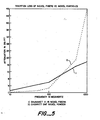
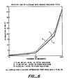
- Figures 5 through 8 are graphs of attenuation versus frequency for cable constructions according to the invention compared to cable constructions according to the prior art.
- Referring to the figures in more detail and particularly referring to Figure 1, there is disclosed according to the invention a high
frequency attenuation cable 2. The cable comprises a core which comprises at least oneconductor 4, a highfrequency absorption medium 6 surrounding the conductor, and a dielectric 8 surrounding the high frequency absorption medium. The high frequency absorption medium comprises soft magnetic elements having an aspect ratio of about 3 or greater. - It should be understood that the core is that portion of the cable which is surrounded by EMI shielding and any outer or protective jacketing.
- The term "soft magnetic elements" refers to elements which are magnetically soft.
- It should also be understood that the aspect ratio is defined as the largest dimension of the soft magnetic element divided by the smallest dimension of the soft magnetic element. For the sake of convenience, soft magnetic elements having an aspect ratio of about 3 or greater may hereafter in this specification be referred to as high aspect ratio elements.
- The high frequency absorption medium serves to allow the passage of low frequency energy but absorbs the high frequency energy. Typically the high frequency absorption medium such as the well-known lossy materials disclosed in the Cornelius et al. references contains
- particulate matter or powder which has an aspect ratio (according to the above definition) much less than 3. See also the lossy materials disclosed in Mayer, USP 3,309,633 and USP 3,191,132, which are incorporated herein by reference. Obviously, this is because the particulate matter or powder consists of spherical or globular particles. It can thus be appreciated that the high aspect ratio soft magnetic elements of the high frequency absorption medium according to the invention are thus physically distinguished from the particulate matter or powder of the prior art high frequency absorption mediums.
- In a further embodiment of the invention, as shown in Figure 2, there is disclosed a high frequency attenuation cable 2' comprising a core. The core comprises at least one
conductor 4, a dielectric 9 surrounding the conductor, a highfrequency absorption medium 6 surrounding the dielectric, and a second layer of dielectric 8 surrounding the high frequency absorption medium. It is thus apparent that in this embodiment the dielectric material is located both inside and outside of the high frequency absorption medium. The high frequency absorption medium comprises soft magnetic elements having an aspect ratio (as previously defined) of about 3 or greater. - In an alternative embodiment of the invention (not shown) the dielectric material may be placed only inside of the high frequency absorption medium so that the dielectric material is located between the conductor and the high frequency absorption medium. Again, the high frequency absorption medium comprises soft magnetic elements having an aspect ratio of about 3 or greater.
- In a preferred embodiment of the invention, the high frequency absorption medium further comprises particulate ',' elements loaded in a polymeric material. Thus, the high frequency absorption medium in the preferred embodiment will comprise both soft magnetic elements having an aspect ratio of about 3 or greater and particulate elements loaded in a polymeric material. The advantages of such a com- binati6n will become apparent hereafter.
- It is contemplated within the scope of the invention that the particulate elements loaded in a polymeric material may be intermingled with the soft magnetic elements so as to form a unitary layer of high frequency absorption material. However, it is also within the scope of the invention to maintain the particulate elements loaded in a polymeric material and the soft magnetic elements as discrete layers of high frequency absorption material.
- The dielectric material may be selected from any of the known dielectric materials usually used in cable constructions. These dielectric materials may be, for example, TEFZEL® (TEFZEL is a copolymer of ethylene and tetrafluoroethylene (ETFE) and is a product of E. I. duPont de Nemours, Wilmington, DE), MYLAR® (MYLAR is polyethylene teraphthalate (PET) and is a product of E. I. duPont de Nemours, Wilmington, DE), or polyethylene. It is preferred that the dielectric material be a high dielectric material as disclosed in copending U.S. Serial No.698,645 filed February 6, 1986, entitled "High Frequency Attenuation Cable and Harness," which is incorporated herein. According to this disclosure, the high dielectric material has a dielectric constant greater than about 5 and is insulative with respect to the high frequency absorption medium. However, it is most preferred that the dielectric material be polyvinylidene fluoride, commercially available as KYNARe (a product of Pennwalt Corp., Philadelphia, PA). The polyvinylidene fluoride is preferred over the other dielectric materials in that it has a dielectric constant ( of about 5-10 depending on frequency and method of manufactur) which is much higher than that found in the other dielectric materials ( of about 2-3 for polyethylene). It has been found that the higher dielectric constant of the polyvinylidene fluoride leads to improved properties as will become apparent hereafter.
- As stated previously, the soft magnetic elements have an aspect ratio of about 3 or greater. It is preferred that these soft magnetic elements be selected from the group of fibers and flakes. The fibers may be in the form of tow or as chopped fibers. It is thus apparent that depending upon the particular configuration of the soft magnetic element selected, the soft magnetic element may (and usually will) have an aspect ratio of substantially greater than 3.
- It is, of course, known that fibers of similar materials have already been used in cable constructions. See, e.g., "Stainless Steel, the 'Invisible' Conductive Filler for Plastics", J. C. Neblo and R. P. Tolokaw, EMC Technology, pp. 43-46 (October-December 1984). This use of fibers has so far been limited to inclusion in EMI shielding. However, the function of EMI shielding is substantially different from the function of a high frequency absorption medium. In the high frequency absorption medium, the fibers act to absorb high frequency energy from the conductor whereas the fibers in the EMI shielding serve to shield the cable core from externally generated interference by reflecting the unwanted interference.
- It must be appreciated that while the use of particulate elements loaded in a polymeric material have been previously disclosed, for example, in the Cornelius et al. references, such materials have never before been used in conjunction with high aspect ratio elements in a high frequency absorption medium. Certainly, the dramatic increase in high frequency attenuation could not have been envisioned. For the purposes of the present invention it is preferred that the particulate elements loaded in a polymeric material comprise ferrite-loaded VITONe. (VITON is a copolymer of vinylidene fluoride and hexafluoropropylene and is a product of E. I. du Pont de Nemours, Wilmington, DE.)
- It is also preferred that the soft magnetic elements be selected from the group consisting of ferromagnetic and ferrimagnetic materials. More preferably the soft magnetic elements are selected from the group consisting of ferrites, nickel-plated carbon, stainless steel, and nickel, and nickel-iron alloys (such as mumetal, permalloy, supermalloy, etc.). The stainless steels contemplated within the scope of the invention are those stainless steels which are naturally ferromagnetic or become ferromagnetic due to processing.
- It is, of course, contemplated within the scope of the invention that the cable construction may include any other layers of material commonly included in cables of this type. It is preferred that the cable in any case include EMI shielding means surrounding the high frequency absorption medium and further include an outer jacket surrounding the EMI shielding means.
- Referring again to the figures, and in particular referring to Figures 3 and 4, there are shown two embodiments of cable harnesses. Each of the cable harnesses with each cable having a core. The core may be any of the cores previously discussed above. The particular embodiment of the
cable harness 20 shown in Figure 3 comprises a plurality ofcables 22 each having a core comprising at least oneconductor 24 surrounded by a highfrequency absorption medium 26 which is in turn surrrounded bydielectric material 28. The construction further includes EMI shielding means 30 surrounding each of the cores andouter jacket 32 surrounding each of the EMI shielding means. The cable construction finally comprises protectiveouter jacketing 34 surrounding the plurality of cables. - Turning now to Figure 4, the
cable 40 comprises a plurality ofcables 42 and cores. In each core there is at least oneconductor 44 surrounded by a highfrequency absorption medium 46 which is in turn surrounded bydielectric material 48. The cable harness further comprises gross EMI shielding means 50 surrounding the plurality of cables and protectiveouter jacketing 52 surrounding the gross EMI shielding means. - As previously described in connection with the cable cores, the high frequency absorption medium in the cable harnesses comprises soft magnetic elements having an aspect ratio of about 3 or greater. These soft magnetic elements may take the form of fibers or flakes. The high frequency absorption medium may also comprise particulate elements loaded in a polymeric material. In a preferred embodiment the particulate elements loaded in a polymeric material comprise ferrite-loaded VITON. In a most preferred embodiment, the dielectric material comprises polyvinylidene fluoride.
- In either of the cable constructions shown in Figures' 3 and 4, the dielectric material may be located inside or outside of the high frequency absorption medium or both inside and outside of the high frequency absorption medium.
- The advantages of the invention will become more apparent after reference to the following examples.
- Two samples were prepared to illustrate the difference in properties obtained when using high aspect ratio elements (in this case fibrous material having an aspect ratio greater than 3) and when using powder. Those samples were prepared by placing the matter (nickel fibers or nickel powder) and a central conductor into a plastic container having a low dielectric constant. The ends of the container were sealed and an EMI shielding means placed around the container. The attenuation of each sample versus frequency was then measured. The results are plotted on Figure 5. As can be seen from Figure 5, the sample containing the fibers,
sample 1, was far superior in the frequency range of 10 to 100 MHz whereasSample 2, the sample containing the powder, only exhibited superior properties at much higher frequencies.' These results demonstrate the effectiveness of high aspect ratio elements over particulate material. - Three samples were prepared to illustrate the effect on attenuation of various insulations.
Samples Sample sample 1 the insulation was TEFZEL and inSample 2 the insulation was KYNAR.Sample 3 was prepared in an identical manner toSamples - The attenuation of the samples versus frequency were measured and plotted on Figure 6. As can be seen,
Samples Sample 1 exhibited superior properties. AlthoughSample 2 contained the preferred KYNAR insulation it is believed that the presence of a low dielectric material, the MYLAR, negated the effectiveness of the KYNAR material.Sample 3, which only contained the KYNAR, performed better than all of the samples. Of particular note, in the frequency range of 10 to 100 MHz,Sample 3 performed in marked contrast toSamples - Three samples were prepared.
Sample 1 comprised 304 stainless steel fiber tow braided onto a conductor. The stainless steel has become so highly oriented that it is magnetic. This was in turn surrounded by KYNAR insulation.Sample 2 was prepared in a manner identical to sample 1 except that the stainless steel braid was saturated with particulate ferrite-loaded VITON lossy compound.Sample 3 was prepared by placing a layer of particulate ferrite-loaded VITON over a conductor which in turn was surrounded by a layer of TEFZEL insulation. The results are plotted on Figure 7. - As can be seen in the figure,
Samples Sample 3 in the critical frequency range of 10 to 100 MHz. Beyond 100 MHz,Sample 3 performed better thanSample 1. However,Sample 2 performed much better thanSample 3. These results demonstrate that, in general, high aspect ratio elements perform better than particulate matter alone in the 10 to 100 megahertz frequency range and that in the 100 to 1000 megahertz frequency range, particulate matter alone performs better than high aspect ratio elements alone. Further, the combination of high aspect ratio elements, particulate matter, and KYNAR performs much better over the entire frequency range of 10 to 1000 megahertz than the prior art combination of particulate matter and TEFZEL. - Three samples were prepared to determine the effect of fiber size.
Sample 1 was prepared by the braiding of 7-micron 304 stainless steel tow onto a conductor which in turn was surrounded by KYNAR insulation.Sample 2 was prepared by braiding 4-micron 304 stainless steel tow onto a conductor and then surrounding this with a layer of KYNAR insulation. In the case ofsamples Sample 3 was a standard cable prepared according to specification 55FA0311-20, published by Raychem Corporation, which is incorporated herein by reference. According to this specification, the cable has a stranded conductor surrounded by particulate ferrite loaded in a polymeric material which is in turn surrounded by TEFZEL insulation. - As can be seen in Figure 8, the samples with the fibrous material,
samples Sample 2 which has the 4-micron fibers performs very closely to the standard cable having the particulate matter in the frequency range of 100 to 1000 MHz. - What the results in Figure 8 illustrate is that as the size of the fiber decreases, that is the higher its aspect ratio, the fiber will still perform as a fiber in the 10 to 100 MHz range, but in the 100 to 1000 MHz range these higher aspect ratio fibers will tend to perform like particulates. Thus, the advantage of combining fibers and particulates as illustrated best by
sample 2 in Figure 7 can be nearly obtained by simply using fibers having a very high aspect ratio as illustrated bysample 2 in Figure 8. - In view of the above, it can be seen that the performance of cables is dependent on a number of factors including the type of high frequency absorption material and the type of insulation. After reviewing the examples it can be seen that cables having high aspect ratio material perform better than cables having particulate material and cables having high aspect ratio material, particulate material and KYNAR insulation performed better than cables having particulate matter plus low dielectric material. It can thus be appreciated that the cables according to the invention perform better than the prior art materials in the frequency range of 10 to 100 MHz and in some cases better than the prior art materials in the frequency range of 100 to 1000 MHz.
- While the invention has been described herein in accordance with certain preferred embodiments thereof, many modifications and changes will be apparent to those skilled in the art. Accordingly, it is intended by the appended claims to cover all such modifications and changes as fall within the true spirit and scope of the invention.
Claims (10)
Applications Claiming Priority (2)
| Application Number | Priority Date | Filing Date | Title |
|---|---|---|---|
| US69864285A | 1985-02-06 | 1985-02-06 | |
| US698642 | 1985-02-06 |
Publications (2)
| Publication Number | Publication Date |
|---|---|
| EP0190940A2 true EP0190940A2 (en) | 1986-08-13 |
| EP0190940A3 EP0190940A3 (en) | 1988-08-10 |
Family
ID=24806093
Family Applications (1)
| Application Number | Title | Priority Date | Filing Date |
|---|---|---|---|
| EP86300837A Withdrawn EP0190940A3 (en) | 1985-02-06 | 1986-02-06 | High frequency attenuation cable and harness |
Country Status (7)
| Country | Link |
|---|---|
| EP (1) | EP0190940A3 (en) |
| JP (1) | JPS61190813A (en) |
| KR (1) | KR860006807A (en) |
| AU (1) | AU5323686A (en) |
| BR (1) | BR8600492A (en) |
| CA (1) | CA1255766A (en) |
| ES (1) | ES8707012A1 (en) |
Cited By (8)
| Publication number | Priority date | Publication date | Assignee | Title |
|---|---|---|---|---|
| EP0525925A1 (en) * | 1991-07-22 | 1993-02-03 | Champlain Cable Corporation | Metal-coated shielding materials |
| EP0528611A1 (en) * | 1991-08-21 | 1993-02-24 | Champlain Cable Corporation | Conductive polymeric shielding materials and articles fabricated therefrom |
| EP0624885A1 (en) * | 1993-05-10 | 1994-11-17 | Alcatel Cable | Cable usable within the telecommunications field |
| WO2000074080A1 (en) * | 1999-06-02 | 2000-12-07 | Composite Materials, L.L.C. | An article shielded against emi and rfi |
| GB2366068A (en) * | 2000-08-10 | 2002-02-27 | Neoterics Ltd | Reducing RF-induced longitudinal currents in conductors |
| GR1009975B (en) * | 2020-07-29 | 2021-04-14 | Εμμ. Κουβιδης Α.Β.Ε.Ε. | System of plastic pipes, junction boxes and accessories for electrical installations offering protection against electromagnetic radiation |
| US11452202B2 (en) | 2020-12-16 | 2022-09-20 | Raytheon Company | Radio frequency filtering of printed wiring board direct current distribution layer |
| US11955941B2 (en) | 2020-07-24 | 2024-04-09 | Raytheon Company | Radio frequency filtered interface |
Families Citing this family (1)
| Publication number | Priority date | Publication date | Assignee | Title |
|---|---|---|---|---|
| GB2179196B (en) * | 1985-08-08 | 1989-01-11 | Pirelli General Plc | Electric cables |
Citations (4)
| Publication number | Priority date | Publication date | Assignee | Title |
|---|---|---|---|---|
| DE1913671U (en) * | 1965-02-16 | 1965-04-15 | Felten & Guilleaume Carlswerk | MAGNETIC LOADED ELECTRICAL CABLE. |
| FR2410343A1 (en) * | 1977-11-29 | 1979-06-22 | Mayer Ferdy | HIGH FREQUENCY ANTI-PARASITE WIRE OR CABLE |
| GB1571113A (en) * | 1976-10-19 | 1980-07-09 | Bicc Ltd | Electric cables and the manufacture thereof |
| EP0081373A2 (en) * | 1981-12-07 | 1983-06-15 | RAYCHEM CORPORATION (a California corporation) | High frequency attenuation cable core |
-
1986
- 1986-02-05 CA CA000501181A patent/CA1255766A/en not_active Expired
- 1986-02-05 AU AU53236/86A patent/AU5323686A/en not_active Abandoned
- 1986-02-05 BR BR8600492A patent/BR8600492A/en not_active IP Right Cessation
- 1986-02-05 ES ES551668A patent/ES8707012A1/en not_active Expired
- 1986-02-06 KR KR1019860000813A patent/KR860006807A/en not_active Application Discontinuation
- 1986-02-06 EP EP86300837A patent/EP0190940A3/en not_active Withdrawn
- 1986-02-06 JP JP61025658A patent/JPS61190813A/en active Pending
Patent Citations (4)
| Publication number | Priority date | Publication date | Assignee | Title |
|---|---|---|---|---|
| DE1913671U (en) * | 1965-02-16 | 1965-04-15 | Felten & Guilleaume Carlswerk | MAGNETIC LOADED ELECTRICAL CABLE. |
| GB1571113A (en) * | 1976-10-19 | 1980-07-09 | Bicc Ltd | Electric cables and the manufacture thereof |
| FR2410343A1 (en) * | 1977-11-29 | 1979-06-22 | Mayer Ferdy | HIGH FREQUENCY ANTI-PARASITE WIRE OR CABLE |
| EP0081373A2 (en) * | 1981-12-07 | 1983-06-15 | RAYCHEM CORPORATION (a California corporation) | High frequency attenuation cable core |
Cited By (10)
| Publication number | Priority date | Publication date | Assignee | Title |
|---|---|---|---|---|
| EP0525925A1 (en) * | 1991-07-22 | 1993-02-03 | Champlain Cable Corporation | Metal-coated shielding materials |
| EP0528611A1 (en) * | 1991-08-21 | 1993-02-24 | Champlain Cable Corporation | Conductive polymeric shielding materials and articles fabricated therefrom |
| EP0624885A1 (en) * | 1993-05-10 | 1994-11-17 | Alcatel Cable | Cable usable within the telecommunications field |
| FR2705161A1 (en) * | 1993-05-10 | 1994-11-18 | Alcatel Cable | Cable usable in the field of telecommunications. |
| US5530206A (en) * | 1993-05-10 | 1996-06-25 | Alcatel Cable | Telecommunication cable |
| WO2000074080A1 (en) * | 1999-06-02 | 2000-12-07 | Composite Materials, L.L.C. | An article shielded against emi and rfi |
| GB2366068A (en) * | 2000-08-10 | 2002-02-27 | Neoterics Ltd | Reducing RF-induced longitudinal currents in conductors |
| US11955941B2 (en) | 2020-07-24 | 2024-04-09 | Raytheon Company | Radio frequency filtered interface |
| GR1009975B (en) * | 2020-07-29 | 2021-04-14 | Εμμ. Κουβιδης Α.Β.Ε.Ε. | System of plastic pipes, junction boxes and accessories for electrical installations offering protection against electromagnetic radiation |
| US11452202B2 (en) | 2020-12-16 | 2022-09-20 | Raytheon Company | Radio frequency filtering of printed wiring board direct current distribution layer |
Also Published As
| Publication number | Publication date |
|---|---|
| BR8600492A (en) | 1986-10-21 |
| JPS61190813A (en) | 1986-08-25 |
| AU5323686A (en) | 1986-08-14 |
| EP0190940A3 (en) | 1988-08-10 |
| ES8707012A1 (en) | 1987-07-01 |
| ES551668A0 (en) | 1987-07-01 |
| KR860006807A (en) | 1986-09-15 |
| CA1255766A (en) | 1989-06-13 |
Similar Documents
| Publication | Publication Date | Title |
|---|---|---|
| US5206459A (en) | Conductive polymeric shielding materials and articles fabricated therefrom | |
| US5171937A (en) | Metal-coated shielding materials and articles fabricated therefrom | |
| US4499438A (en) | High frequency attenuation core and cable | |
| US4816614A (en) | High frequency attenuation cable | |
| US5262592A (en) | Filter line cable featuring conductive fiber shielding | |
| US4486721A (en) | High frequency attenuation core and cable | |
| US5170010A (en) | Shielded wire and cable with insulation having high temperature and high conductivity | |
| US4408089A (en) | Extremely low-attenuation, extremely low radiation loss flexible coaxial cable for microwave energy in the gigaHertz frequency range | |
| US5956445A (en) | Plenum rated cables and shielding tape | |
| US5262591A (en) | Inherently-shielded cable construction with a braided reinforcing and grounding layer | |
| CA1174309A (en) | Electric cables with improved shielding members | |
| US6812408B2 (en) | Multi-pair data cable with configurable core filling and pair separation | |
| US4506235A (en) | EMI Protected cable, with controlled symmetrical/asymmetrical mode attenuation | |
| EP0329188B1 (en) | Noise-suppressing high voltage cable and method of manufacturing thereof | |
| CA2555330C (en) | Bundled cable using varying twist schemes between sub-cables | |
| EP0053036A1 (en) | Electrical system | |
| US5414215A (en) | High frequency electric cable | |
| EP0190940A2 (en) | High frequency attenuation cable and harness | |
| US20070026742A1 (en) | UTP cable for transmitting high frequency signal | |
| US20180268965A1 (en) | Data cable for high speed data transmissions and method of manufacturing the data cable | |
| US20090283288A1 (en) | Communication cable for high frequency data transmission | |
| EP0190939A2 (en) | High frequency attenuation cable and harness | |
| US5530206A (en) | Telecommunication cable | |
| US5763836A (en) | Retractable multiconductor coil cord | |
| JP2015038857A (en) | Communication cable containing discontinuous shield tape and discontinuous shield tape |
Legal Events
| Date | Code | Title | Description |
|---|---|---|---|
| PUAI | Public reference made under article 153(3) epc to a published international application that has entered the european phase |
Free format text: ORIGINAL CODE: 0009012 |
|
| 17P | Request for examination filed |
Effective date: 19860213 |
|
| AK | Designated contracting states |
Kind code of ref document: A2 Designated state(s): AT BE CH DE FR GB IT LI NL SE |
|
| RAP1 | Party data changed (applicant data changed or rights of an application transferred) |
Owner name: RAYCHEM CORPORATION (A DELAWARE CORPORATION) |
|
| PUAL | Search report despatched |
Free format text: ORIGINAL CODE: 0009013 |
|
| AK | Designated contracting states |
Kind code of ref document: A3 Designated state(s): AT BE CH DE FR GB IT LI NL SE |
|
| 17Q | First examination report despatched |
Effective date: 19900906 |
|
| STAA | Information on the status of an ep patent application or granted ep patent |
Free format text: STATUS: THE APPLICATION IS DEEMED TO BE WITHDRAWN |
|
| 18D | Application deemed to be withdrawn |
Effective date: 19910117 |
|
| RIN1 | Information on inventor provided before grant (corrected) |
Inventor name: LLOYD, RICHARD Inventor name: LUNK, HANS E. |