EP0192418A2 - Bone stapler cartridge - Google Patents
Bone stapler cartridge Download PDFInfo
- Publication number
- EP0192418A2 EP0192418A2 EP86300985A EP86300985A EP0192418A2 EP 0192418 A2 EP0192418 A2 EP 0192418A2 EP 86300985 A EP86300985 A EP 86300985A EP 86300985 A EP86300985 A EP 86300985A EP 0192418 A2 EP0192418 A2 EP 0192418A2
- Authority
- EP
- European Patent Office
- Prior art keywords
- driver
- staples
- passageway
- cartridge
- opening
- Prior art date
- Legal status (The legal status is an assumption and is not a legal conclusion. Google has not performed a legal analysis and makes no representation as to the accuracy of the status listed.)
- Granted
Links
Images


Classifications
-
- A—HUMAN NECESSITIES
- A61—MEDICAL OR VETERINARY SCIENCE; HYGIENE
- A61B—DIAGNOSIS; SURGERY; IDENTIFICATION
- A61B17/00—Surgical instruments, devices or methods, e.g. tourniquets
- A61B17/10—Surgical instruments, devices or methods, e.g. tourniquets for applying or removing wound clamps, e.g. containing only one clamp or staple; Wound clamp magazines
-
- A—HUMAN NECESSITIES
- A61—MEDICAL OR VETERINARY SCIENCE; HYGIENE
- A61B—DIAGNOSIS; SURGERY; IDENTIFICATION
- A61B17/00—Surgical instruments, devices or methods, e.g. tourniquets
- A61B17/068—Surgical staplers, e.g. containing multiple staples or clamps
- A61B17/0682—Surgical staplers, e.g. containing multiple staples or clamps for applying U-shaped staples or clamps, e.g. without a forming anvil
-
- A—HUMAN NECESSITIES
- A61—MEDICAL OR VETERINARY SCIENCE; HYGIENE
- A61B—DIAGNOSIS; SURGERY; IDENTIFICATION
- A61B17/00—Surgical instruments, devices or methods, e.g. tourniquets
- A61B17/56—Surgical instruments or methods for treatment of bones or joints; Devices specially adapted therefor
- A61B17/58—Surgical instruments or methods for treatment of bones or joints; Devices specially adapted therefor for osteosynthesis, e.g. bone plates, screws, setting implements or the like
- A61B17/88—Osteosynthesis instruments; Methods or means for implanting or extracting internal or external fixation devices
-
- A—HUMAN NECESSITIES
- A61—MEDICAL OR VETERINARY SCIENCE; HYGIENE
- A61B—DIAGNOSIS; SURGERY; IDENTIFICATION
- A61B17/00—Surgical instruments, devices or methods, e.g. tourniquets
- A61B2017/00535—Surgical instruments, devices or methods, e.g. tourniquets pneumatically or hydraulically operated
- A61B2017/00544—Surgical instruments, devices or methods, e.g. tourniquets pneumatically or hydraulically operated pneumatically
Definitions
- This invention relates to staple cartridges used in devices for driving staples.
- U .S. Patents No.'s 4,540,110, 4,527,726 and 4,500,025 describe generally the same bone stapling device described in this application which has numerous novel design features which facilitate driving staples into bone portions during surgery.
- the bone stapler described in both those applications and in this application are staplers of the type adapted for use with generally U-shaped staples.
- the staplers comprise a housing having a passageway extending from an inlet opening to an outlet opening, which passageway is adapted to guide a single staple moved from the inlet to the outlet opening.
- Means are provided for biasing a stack of staples into the inlet opening, together with a driver having an end portion adapted to engage the central portion of a staple.
- the driver is mounted on the housing for sliding movement between a load position spaced from the inlet opening to afford movement of one of the staples of the stack into the passageway, along the passageway with the end portion of the driver pushing the staple, and to an eject position at which the driver pushes the staple out the outlet opening.
- manually activatable drive means are provided for rapidly and forcefully propelling the driver along the passageway from its load position to its eject position to move a staple from the inlet opening to the outlet opening and drive the staple into portions of bone adjacent the outlet opening.
- cartridge which precludes leaving a staple in the stapler that could be inadvertently driven after the cartridge is removed.
- cartridge comprises guide wall means defining an inner surface at the end of a stack of staples opposite a follower and side walls projecting normal to the inner surface, which side walls have opposed transverse openings at the inner surface and aligned with the passageway when the cartridge is in the stapler.
- the inner surface defined by the guide wall means defines a portion of the passageway- for the driver at the inlet opening, with the driver being movable through the transverse openings and along the inner surface between its load and the eject positions.
- the present invention provides a cartridge and a stapler generally of the types described above, but which include novel attachment means for releasable attaching the cartridge to the stapler that are less expensive to manufacture and significantly easier to use than the attachment means described in the applications described above.
- a cartridge adapted for use in a stapler for driving generally U-shaped staples which stapler comprises a housing having a passageway extending from an inlet opening to an outlet opening adapted to guide a single staple between those openings, a driver mounted on the housing for sliding movement between a load position spaced from the inlet opening to afford movement of one of the staples into the passageway, along the passageway pushing the staple to an eject position at which the driver pushes the staple out the outlet opening; and manually activatable drive means for propelling the driver along the passageway from its load to its eject position.
- the housing includes a support wall having an inner surface defining a socket adapted to receive the cartridge at the inlet opening, which support wall has a through opening between its inner and outer surfaces.
- the cartridge includes a case comprising a guide wall defining an inner surface and side walls projecting generally normal to the inner surface, the side walls having opposed transverse openings at the inner surface.
- the guide wall is adapted to be received in the socket with the inner surface defining a portion of the passageway at the inlet opening and the transverse openings aligned with the passageway so that the driver can be moved through the openings and along the inner surface between its load and eject positions.
- the cartridge also includes a stack of staples within the case, a follower on the side of the stack of staples opposite the passageway and movable within the case with the stack of staples, a spring for biasing the follower and the stack of staples toward the inner surface, and the novel attachment means adapted for releasably retaining the case in engagement with the housing.
- Those attachment means comprise a locking member mounted on the guide wall for rotation about an axis generally normal to the inner surface, projecting from the side of the guide wall opposite the inner surface, having a spacing portion of a first maximum radius extending from the guide wall for a first predetermined distance about equal to the distance between the inner and outer surfaces of the support wall with the first maximum radius affording rotation of the spacing portion within a first central portion of the opening in the support wall, and having a locking portion with at least one lug projecting beyond the maximum radius at the distal end of the first portion.
- the lug is adapted to pass through a second portion of the opening through the support wall in a release position of the locking member relative to the case, and is adapted to engage the second surface of the support wall at positions spaced from its release position to hold the cartridge on the housing.
- the locking portion of the locking member has two opposite lugs projecting beyond the maximum radius of the spacing portion
- the opening through the support wall has two opposite second portions adapted to pass the lugs in the release portion of the locking member
- -the housing includes cam surfaces around the second portions of the opening and intersecting the outer surface of the support wall to facilitate rotation of the locking member from its release to its locking position when a major portion of the spacing portion of the locking member is in the opening.
- FIG. 1 through 4 there is illustrated a bone stapler to which is attached a cartridge 21 according to the present invention, which stapler is generally designated by the reference numeral 10.
- the stapler 10 is adapted for use with generally U -shaped staples 11 (Figure 11).
- Each of the staples 11 comprises a central portion 12 and two generally parallel leg portions 13 having pointed distal ends and projecting generally in the same direction from opposite ends of its central portion 12, which leg portion 13 preferably diverge by about 1 or 2 degrees so that the driven staple will provide a compressive effect on portions of bone joined by it.
- the stapler 10 comprises a pistol-shaped housing 14 having a passageway 16 ( Figure 3 and 4) extending from an inlet opening 18 to an outlet opening 20, which passageway 16 is adapted to guide one of the staples 11 from the inlet opening 18 to the outlet opening 20 with the distal ends of the staple 11 leading.
- Means are provided for biasing a stack of the staples 11 contained in the replaceable cartridge 21 into the inlet opening 18.
- a driver 22 having an end portion 24 adapted to engage the central portion 12 of one of the staples 11 is mounted on the housing 14 for sliding movement between a load position ( Figure 3) with the driver 22 spaced from the inlet opening 18 to afford movement of one of the staples 11 into the passageway 16, along the passageway 16 with its end portion 24 pushing the staple, to an eject position ( Figure 4) at which the end portion 24 of the driver 22 pushes the staple 11 out of the outlet opening 20 and at which eject position the driver 22 is stopped.
- Drive means including an air cylinder assembly 26 powered by air under greater than atmospheric pressure and adapted to be manually activated by pulling an actuating trigger 27 into a handle portion 25 of the housing 14 are provided for rapidly and forcefully propelling the driver 22 along the passageway 16 from the load position to the eject position to move the staple 11 from the inlet opening 18 to the outlet opening 20.
- the driver 22 comprises a blade-like portion on which its end portion 24 is formed, and a cylindrical portion 17 that moves within a cylindrical guide bore 19 in the housing 14, to which the cylindrical portion 17 the blade-like portion is attached by a pin 23 through an enlarged cylindrical part 17a of the cylindrical portion 17 that slides in close fitting engagement in the guide bore 19 and has through ports (not shown) to allow air to escape from in front of it.
- the drive means for propelling the driver 22 comprises the air cylinder assembly 26 which includes a cylinder 28 partially defined by a cylindrical inner surface 29 of the housing 14 concentric with the guide bore 19, which inner surface 29 has first and second ends 30 and 31, and a piston 32 within the cylinder 28 integral with an end portion of the driver 22 opposite its end portion 24.
- This piston 32 is in slidable sealing engagement with the cylindrical inner surface 29, and is movable along the inner surface 29 between a first position adjacent the first end 30 of the cylinder 28 at which the piston 32 is located when the driver 22 is in its load position and to which the piston 32 is biased by a main spring 33 within the cylinder 28 and the housing 14; and a second position adjacent the second end 31 of the cylinder 28 at which the piston 32 is positioned when the driver 22 is in its eject position.
- the end of the main spring 33 opposite the piston 32 is supported against an annular inwardly projecting ledge on a guide collar 35 which guide collar 35 has an outwardly projecting rim fixed against an inwardly projecting lip in the housing 14 by an anchor ring 35b threadably engaged with the housing 14.
- the inner surface of the inwardly projecting ledge is in close engagement around the driver 22 and carries a pin 35c positioned in a longitudinal groove 35d in the driver 22 to allow longitudinal movement of the driver 22 between its load and eject positions while the pin 35c prevents rotation of the driver 22 relative to the housing 14.
- the actuating trigger 27 by which the air cylinder assembly 26 is actuated is included in a valve assembly 34 comprising the housing 14 having a bore opening through the front of its handle portion 25 in which a guide spool 39 is fixed and having an inlet port 36 and first and second outlet ports 37 and 38 communicating with the bore.
- An actuator 40 coupled to the actuating trigger 27 by a set screw (not shown) is manually movable within the guide spool 39 from an outer blocking position ( Figure 3) at which an 0-ring 41 around a groove in the actuator 40 engages a seat around and closes the inlet port 36, and clearance between a small diameter portion 42 of the actuator 40 and the inner surface of the guide spool 39 connects the outlet ports 37 and 38 through transverse passageways in the guide spool 39; and an inner activate position ( Figure 4) with the O-ring 41 separated from the seat to connect the inlet port 36 and the first outlet port 37 past the small diameter portion 42 of the actuator 40, and at which a larger diameter 43 portion of the actuator 40 essentially closes the transverse passageways in the guide spool 39 leading to the second outlet port 38.
- a spring 44 provides means for biasing the actuator 40 to its outer blocking position, against which spring 44 the actuator 40 may be manually moved or pulled to its activate position by the actuating trigger 27.
- the housing 14 has an outlet passageway 46 which communicates with the cylinder 28 adjacent its second end 31, communicates with the second outlet port 38, and is adapted to be coupled to a portion of a hose (not shown) leading to air at atmospheric pressure through a conventional surgical air inlet connector, a female half 45 of which is formed, in the housing 14.
- the housing 14 also has an inlet passageway 47 including an enlarged reservoir portion 48 (which provides sufficient air volume to quickly move the piston 32) coupled to the inlet port 36 and a smaller portion 49 adapted to be coupled to a source of air under greater than atmospheric pressure through the female coupling half 45.
- a transfer passageway 51 coupled between the first outlet port 37 and communicating with the cylinder 28 adjacent its first end 30.
- the cartridge 21, best seen in Figures 8 through 11, includes a case 54 comprising a guide wall 55 defining an inner surface 56 at one end of the stack of staples 11, side walls 57 projecting normal to the inner surface 56, and an end wall 53 opposite the guide wall 55.
- the side walls 57 have opposed transverse openings 58 adjacent the inner surface 56 and an end portion of the cartridge 21 including the guide wall 55 is received in a socket 59 defined by an inner surface of a support wall 61 included in the housing 14 with the transverse openings 58 aligned with the passageway 16 and the inner surface 56 defining a portion of the passageway 16 at its inlet opening 18 so that the driver 22 is movable through the transverse openings 58 and along the inner surface 56 between its load and eject positions.
- the cartridge 21 further includes a follower 60 on the side of the stack of staples 11 opposite the inner surface 56 and passageway 16, which follower 60 is movable within the case 54 with the stack of staples 11, and the coil spring 15 between the end wall 53 of the case 54 and the follower 60 for biasing the following 60 and the stack of staples 11 toward the inner surface 56.
- the driver 22 moves through the transverse openings 58 and along the inner surface 56 during movement from its load to its eject position, the driver 22 will carry with it the staple 11 pressed against the inner surface 56 by the follower 60 and spring 15.
- the cartridge 21 When removed, the cartridge 21 will carry with it all of the staples 11 remaining in the stapler 10 so that, with the cartridge 21 removed, it will be impossible to inadvertently fire a staple 11 from the stapler 10.
- Means for releasably retaining the cartridge 21 in the socket 59 in the housing 14 is provided by the support wall 61 (beat seen in Figures 6 and 7) having a through opening 62 between its inner surface defining the socket 59 and an outer surface 63 generally parallel to its inner surface at the bottom of the socket 59, which through opening 62 has a circular central first opening portion 64 and two generally U-shaped opposed second opening portions 65 on opposite sides of the central opening portion 64; and the cartridge -21 (best seen in Figures 8-11) having a locking member 66 mounted on the guide wall 55 for rotation about an axis generally normal to the inner surface 56, projecting from the side of the guide wall 55 opposite the inner surface 56, having a spacing portion 68 of a first maximum radius extending from the guide wall 55 for a first predetermined distance about equal to the distance between the inner and outer surfaces of the support wall 61 with the first maximum radius affording rotation of the spacing portion 68 within the central first opening portion 64, and having a locking portion with at least one, and as illustrated, two
- the lugs 70 are adapted to pass through the second portions 65 of the opening 62 in a release position of the locking member 66 relative to the case 54, and have a surface adjacent the support wall 61 in engagement with the outer surface 63 of the support wall 61 at positions of the locking member 66 spaced from its release position to hold the cartridge 21 in the socket 59 on the housing 14.
- the housing 14 includes a cam surface 72 around each of the second portions 65 of the opening 62.
- the cam surfaces 72 intersect the outer surface 63 of the support wall 61 and facilitate rotation of the locking member 66 from its release portion to a position with the lugs 70 along the outer surface 63 of the support wall 61 when the spacing portion 68 of the locking member 66 is in the opening 62.
- engagement between the lugs 70 and the cam surfaces 72 will pull the cartridge 21 firmly into the socket 59, eliminating the necessity for the user to press the cartridge 21 fully to that position prior to rotating the locking member 66.
- the cartridge 21 includes a stack of staples 11, the coil spring 15 and four polymeric moldings that provide the follower 60, the guide wall 55 and a cup-shaped member that includes the side walls 57 and the end wall 53 and is fused to the guide wall 55 to form the case 54, and the locking member 66.
- the locking member 66 has an annular rim 73 on its end opposite the lugs 70, which rim 73 is rotatably received in a recess from the inner surface 56 of the guide wall 55.
- the guide wall 55 has an orifice shaped to pass the lugs 70 and spacing portion 68 of the locking member 66 by slightly deflecting a central portion of the guide wall 55 defining a central portion of the orifice, which central portion of the guide wall 55 will move into a shallow groove 74 around the locking member 66 adjacent the annular rim 73 where the guide wall 55 is retained while the locking member 66 is freely rotatable relative to the guide wall 55.
- the side of the follower 60 opposite the staples 11 has a circular recess that receives a large end of the spring 15, whereas the smaller end of the spring 15 is located around a post 75 projecting from the end wall 53.
- the spring 15 is tapered between the follower 60 and the end wall 53 to reduce the range of pressures that it will apply to the staples 11 as the height of the stack of staples 11 decreases, and to minimize its compressed height and thereby the height of the cartridge 21.
- Means for guiding the follower 60 are provided by grooves 76 in the side walls 57 disposed at right angles to the guide wall 55, shoes 77 formed on the edges of the follower 60 adapted to slide within the grooves 76, and two parallel pins 78 projecting from the end wall 53 received in openings in the follower 60.
- the shoes 77 on the sides of the follower 60 have upwardly projecting parts that prevent the follower 60 from being pushed into the path of the driver 22 after the last staple 11 is ejected from the cartridge 21.
- the bone stapler 10 includes blocking means for automatically preventing movement of the driver 22 to its load position from an intermediate position between its load and eject positions with a portion of the driver 22. projecting partially through the cartridge 21 and across the inlet opening 18 to the passageway 16 after the driver 22 has moved from its load to its eject position.
- the drive means may be manually activated a first time by pulling the actuating trigger 27 to drive a staple 11 through the outlet opening 20 and may subsequently be manually activated an additional number of times by pulling the actuating trigger 27 so that the driver 22 will be again propelled to its eject position to further impact that driven staple 11 as may be needed to fully seat the driven staple 11, without driving an additional staple 11 from the cartridge 21.
- reset means manually activated by a reset member or trigger 79 for resetting the blocking means to allow return movement of the driver 22 from its intermediate to its load position so that another staple 11 may be driven.
- the blocking means in the bone stapler 10 comprises a plunger 80 axially slidably mounted in a bore in the housing 14 communicating with the cylinder 28 at its first end 30 for movement in a direction normal to the axis of the cylinder 28 between a nonblocking position ( Figure 3) spaced from within the cylinder 28, to a blocking position ( Figure 4) partially within the cylinder 28 to which the plunger 80 is biased by a spring 81, so that engagement between the plunger 80 and the side of the piston 32 adjacent the first end 30 of the cylinder 28 will define the intermediate position for the piston 32.
- the reset means comprises the reset trigger 79 fastened by a set screw (not shown) to an outer end portion of a spindle 83, which spindle 83 is slidably mounted in a sleeve 82 fixed in a bore opening through the front of the handle portion 25 of the housing 14 for longitudinal sliding movement between an outer position ( Figures 3 and 4) and an inner position (not shown). Also included in the reset means are means in the form of a spring 85 for biasing the reset trigger 79 to its outer position, and cam means on the spindle 83 and reset trigger 79 for moving the plunger 80 from its blocking to its nonblocking position against the bias of spring 81 upon manual movement of the spindle 83 from its outer to its inner position via the reset trigger 79.
- the cam means comprise a semispherical tip 88 on the inner end of the spindle 83, and a surface 89 inclined with respect to the axis of the spindle 83 partially defining a slot in the plunger 80 in which the tip 88 is received to prevent rotation of the plunger 80.
- the slot in the plunger 80 is sufficiently long to afford movement of the plunger 80 from its nonblocking to its blocking position under the influence of the spring 81 after the driver moves toward its eject position.
- the reset trigger 79 may be manually pulled toward the handle portion 25 of the housing 14 which will cause the tip 88 to engage the inclined surface 89 so that the plunger 80 will be pulled back to its nonblocking position. This will allow the piston 32 to return to its first position, and cause the driver 22 to return to its load position under the influence of the main spring 33.
- the bone stapler 10 is designed to afford driving staples of different sizes in that it is made in two separable assemblies including a handle assembly 91 which includes the drive means mounted on one part of the housing 14, and a barrel assembly 92 which defines the passageway 16 and receives the cartridge 21 for staples 11 of one size on another part of the housing 14. Means are provided for releasably engaging the parts of the housing 14, and the driver 22 is separable into a second part 93 included in the handle assembly 91 and connected to the piston 32, and a first part 94 including its end portion 24 which is included in the barrel assembly 92.
- Different barrel assemblies that each have a housing part defining a passageway, a driver part and accept cartridges of a different size of staple may be substituted for the barrel assembly - 92 to afford driving staples of different sizes.
- Means are provided for releasably engaging the first and second parts 94 and 93 of the driver 22 and for releasably engaging the handle and barrel assemblies 91 and 92.
- These means comprise walls on the first part 94 of the driver 22 opposite its end portion 24 defining a socket with an outer portion 96 having a square cross section and an inner portion 97 with a circular cross section; and a tip on the first part 94 of the driver 22 including a distal square portion 99 adapted to slide within the socket through its outer portion 96 and to rotate in its inner portion 97 out of alignment with the outer portion 96 (see Figure 5) with the walls defining the outer portion 96 around a reduced diameter cylindrical portion 100 of the driver's first part 94.
- the part of the housing 14 included in the barrel assembly 92 includes a collar 101 at its end opposite the outlet opening 20 received in a socket in the part of the housing 14 included in the handle assembly 91 with the square portion 99 of the tip out of alignment with the outer portion 96 of the wall defining the socket, with four evenly spaced radially outwardly projecting pins 102 fixed on the collar 101 received in four longitudinally extending slots opening through the end of the housing part included in the handle assembly 91, and with hooks 105 on a ring 103 mounted for rotation about its axis on the housing part included in the handle assembly 91 in engagement with the pins 102 to releasably latch the handle and barrel assemblies 91 and 92 together.
- the barrel assembly 92 can thus be located at different orientations displaced 90 degrees from each other with respect to the handle assembly 91 to provide various orientations of a driven staple 11 relative to the handle portion 25 of the housing 14.
- the ring 103 is rotated against the bias of a coil spring 104 to move the hooks 105 from around the pins 102.
- the handle and barrel assemblies 91 and 92 are pulled apart axially of the driver 22 which pulls the pins 102 from the slots in which they are received and pulls the part of the housing 14 on the barrel assembly 92 along the driver 22 until an inwardly projecting lip (not shown) on that part of the housing 14 engages the end of the enlarged part 17 of the driver 22 adjacent the piston 32, at which position a pin 107a carried by the driver portion 17 is moved by a spring 107b so that a ball 107c will be moved into housing a groove in the housing 14, which engagement will keep the end plug 23 from moving into the guide bore 19 after the handle and barrel assemblies 91 and 92 are separated.
- the handle and barrel assemblies 91 and 92 are then rotated about 45 degrees relative to each other about the axis of the driver 22 to align the square position 99 of the tip with the outer portion 96 of the socket, whereupon the tip may be pulled from the socket and the assemblies 91 and 92 may be separated.
- Reengagement of the handle and barrel assemblies 91 and 92 is accomplished by reversing the steps listed above which will cause a cam surface on the end of the first part 92 of the driver 22 around the end of the socket to move the pin 107a against the spring 107b to release the driver 22.
- camming surfaces 105b on the hooks 105 will cause the collar 101 to automatically rotate to engage the hooks 105 around the pins 102.
- the bone stapler 10 also includes means for indicating to a user ready to fire the stapler 10 whether the driver 22 is in its load position from which a staple 11 can be driven or in its intermediate position.
- An indicating spool 106 is centrally slidably mounted in a removable plug 108 providing a portion of the housing 14 at the first end 30 of the cylinder 28.
- the indicating spool 106 is slidable between an inner position with a flange 109 at its outer end against the outer surface of the plug 108 to which the indicating spool 106 is biased by a spring 110, and an outer position with a portion of the spool 106 adjacent the flange 109, which is painted red, projecting from the plug 108.
- The- piston 32 carries a central headed pin 112 at its end adjacent the first end 30 of the cylinder 28 around which pin 112 is a slidable washer 114 biased against the head of the pin 112 by a spring 113 with a greater spring constant than the spring 110.
- the driver 22 When the driver 22 is in its load position, the head of the pin 112 will enter an opening in the spool 106 while the washer 114 will be pressed against the adjacent end of the indicating spool 106 under the influence of the spring 113 causing the spool 106 to move to its outer position at which its red periphery indicates that the driver 22 is in its load position.
- the indicating spool 106 will move to its inner position under the influence of the spring 110, thereby indicating to a user that the driver 22 is in its intermediate position.
- a cartridge 21 containing a stack of staples 11 is held in the housing 14 by the locking member 66 and the stapler 10 is connected at the coupling half 45 to a hose assembly (not shown) including a central supply of air under greater than atmospheric pressure coupled to the inlet passageway 47, and an outer hose leading to air at atmospheric pressure coupled to the outlet passageway 46.
- the user can utilize a pair of pointed locating members 130 fixed to the housing 14 in positions flanking the outlet opening 20 and projecting generally parallel to the axis of the driver 22 to help position and stabilize bone portions to be stapled in the same plane.
- the stapler 10 can be activated by manually pulling the actuating trigger 27 so that air under greater than atmospheric pressure is coupled through the reservoir 48, valve assembly 34 and transfer passageway 51 to the first end 30 of the cylinder 28 which will cause rapid movement of the piston 32 and thereby the driver 22 from its load position ( Figure 3) spaced from the staple inlet opening 18, and through the cartridge 21 along its inner surface 56 to push the adjacent staple 11 in the stack along the passageway 16 to the outlet opening 20 and drive that staple 11 into adjacent portions of bone ( Figure 4), the driver 22 being stopped at its eject position at the outlet opening 20 by engagement of the piston 32 with a rubber collar 131 at the second end 31 of the cylinder 28.
- the plunger 80 will move into the cylinder 28 under the influence of the spring 81 so that, after the actuating trigger 27 is released and the high pressure air at the first end 30 of the cylinder 28 escapes through the transfer passageway 51, valve assembly 34 and outlet passageway 46 to the hose coupled to atmospheric pressure and the piston 32 moves back toward its first position under the influence of the main spring 33, the piston will be stopped against the periphery of the plunger 80 with the end portion 24 of the driver 22 at an intermediate position extending through the cartridge 21 so that the next staple 11 in the stack of staples 11 can not move into the inlet opening 18 to the passageway 16.
- the user if desired, can then again rapidly move the driver 22 to its eject position by again pulling the actuating trigger 27 as may be desired to further drive or seat the staple 11 previously driven into the bone portions.
- the user wishes to remove the cartridge 21 because it is empty, or to insure that the stapler 10 can not fire another staple 11, or to insert staples with different length leg portions 13, he may do so by manually rotating the locking member 66 to its release position with its lugs 70 aligned with the outer portions 65 of the opening 62 by pushing on one or both of the lugs 70, and then pulling the cartridge 21 from the socket 59 in the housing 14. He can them be sure that no staples 11 remain in the stapler 10, since the entire remaining stack of staples 11 (if any) remains in the cartridge 21.
- the same or a new cartridge 21 of staples 11 may again be loaded into the stapler 10 by inserting the cartridge 21 into the socket 59 in the housing 14 and then rotating the locking member 66 from its release position, which will cause the lugs 70 to move along the cam surfaces 72 and onto the outer surface 63 of the support wall 61 to pull the cartridge 21 fully into the socket 59 and hold it in place.
- the user wishes to drive staples of a different width along its central portion 12, he may also do that by substituting an appropriate different barrel assembly for the barrel assembly 92 being used, which different barrel assembly is adapted to accommodate staples 11 of that width.
- Such substitution is easily accomplished by rotating the locking collar 103 to release the two parts of the housing 14, pulling and relatively rotating the housing parts with respect to the longitudinal axis of the driver 22 (as is described in greater detail above) which will cause the square portion 99 on the first part 94 of the driver 22 to align with the square cross section portion 96 of walls defining the socket in the second part 93 of the driver 22 in which the square portion 99 is received, and pulling the first and second parts of the housing 14 and driver 22 away from each other to pull the square portion 99 from the socket and separate them.
- the different barrel assembly can then be assembled on the handle assembly 91 by reversing the separating steps.
Abstract
Description
- This invention relates to staple cartridges used in devices for driving staples.
- U.S. Patents No.'s 4,540,110, 4,527,726 and 4,500,025 describe generally the same bone stapling device described in this application which has numerous novel design features which facilitate driving staples into bone portions during surgery. Generally, the bone stapler described in both those applications and in this application are staplers of the type adapted for use with generally U-shaped staples. The staplers comprise a housing having a passageway extending from an inlet opening to an outlet opening, which passageway is adapted to guide a single staple moved from the inlet to the outlet opening. Means are provided for biasing a stack of staples into the inlet opening, together with a driver having an end portion adapted to engage the central portion of a staple. The driver is mounted on the housing for sliding movement between a load position spaced from the inlet opening to afford movement of one of the staples of the stack into the passageway, along the passageway with the end portion of the driver pushing the staple, and to an eject position at which the driver pushes the staple out the outlet opening. Also manually activatable drive means are provided for rapidly and forcefully propelling the driver along the passageway from its load position to its eject position to move a staple from the inlet opening to the outlet opening and drive the staple into portions of bone adjacent the outlet opening.
- The novel features described in the above mentioned prior applications include a removable cartridge which precludes leaving a staple in the stapler that could be inadvertently driven after the cartridge is removed. The case in that cartridge comprises guide wall means defining an inner surface at the end of a stack of staples opposite a follower and side walls projecting normal to the inner surface, which side walls have opposed transverse openings at the inner surface and aligned with the passageway when the cartridge is in the stapler. The inner surface defined by the guide wall means defines a portion of the passageway- for the driver at the inlet opening, with the driver being movable through the transverse openings and along the inner surface between its load and the eject positions. Thus because all of the staples remain within the cartridge until they are driven, the user can be assured that all the staples are removed from the stapler when the cartridge is removed.
- The present invention provides a cartridge and a stapler generally of the types described above, but which include novel attachment means for releasable attaching the cartridge to the stapler that are less expensive to manufacture and significantly easier to use than the attachment means described in the applications described above.
- According to the present invention there is provided a cartridge adapted for use in a stapler for driving generally U-shaped staples, which stapler comprises a housing having a passageway extending from an inlet opening to an outlet opening adapted to guide a single staple between those openings, a driver mounted on the housing for sliding movement between a load position spaced from the inlet opening to afford movement of one of the staples into the passageway, along the passageway pushing the staple to an eject position at which the driver pushes the staple out the outlet opening; and manually activatable drive means for propelling the driver along the passageway from its load to its eject position. The housing includes a support wall having an inner surface defining a socket adapted to receive the cartridge at the inlet opening, which support wall has a through opening between its inner and outer surfaces. The cartridge includes a case comprising a guide wall defining an inner surface and side walls projecting generally normal to the inner surface, the side walls having opposed transverse openings at the inner surface. The guide wall is adapted to be received in the socket with the inner surface defining a portion of the passageway at the inlet opening and the transverse openings aligned with the passageway so that the driver can be moved through the openings and along the inner surface between its load and eject positions. The cartridge also includes a stack of staples within the case, a follower on the side of the stack of staples opposite the passageway and movable within the case with the stack of staples, a spring for biasing the follower and the stack of staples toward the inner surface, and the novel attachment means adapted for releasably retaining the case in engagement with the housing. Those attachment means comprise a locking member mounted on the guide wall for rotation about an axis generally normal to the inner surface, projecting from the side of the guide wall opposite the inner surface, having a spacing portion of a first maximum radius extending from the guide wall for a first predetermined distance about equal to the distance between the inner and outer surfaces of the support wall with the first maximum radius affording rotation of the spacing portion within a first central portion of the opening in the support wall, and having a locking portion with at least one lug projecting beyond the maximum radius at the distal end of the first portion. The lug is adapted to pass through a second portion of the opening through the support wall in a release position of the locking member relative to the case, and is adapted to engage the second surface of the support wall at positions spaced from its release position to hold the cartridge on the housing.
- Preferably the locking portion of the locking member has two opposite lugs projecting beyond the maximum radius of the spacing portion, the opening through the support wall has two opposite second portions adapted to pass the lugs in the release portion of the locking member, and-the housing includes cam surfaces around the second portions of the opening and intersecting the outer surface of the support wall to facilitate rotation of the locking member from its release to its locking position when a major portion of the spacing portion of the locking member is in the opening.
- The above and additional novel features will be described with reference to the accompanying drawing wherein like numbers refer to like parts in the several views and wherein:
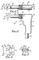
- Figure 1 is a top view of a bone stapler including the improved cartridge according to the present invention;
- Figure 2 is a side view of the bone stapler of Figure 1;
- Figure 3 is an enlarged sectional view taken along line 3-3 of Figure 1;
- Figure 4 is an enlarged sectional view taken along line 3-3 of Figure 1 and similar to Figure 3, but in which drive means has been activated to drive a staple;
- Figure 5 is an enlarged sectional view taken approximately along lines 5-5 of Figure 4;
- Figure 6 is an enlarged fragmentary view of a barrel assembly on the bone stapler of Figure 1 from which the cartridge has been removed;
- Figure 7 is a sectional view taken approximately along lines 7-7 of Figure 6;
- Figure 8 is an enlarged perspective view of the cartridge according to the present invention shown in combination with the stapler in Figures 1 through 4;
- Figure 9 is a vertical sectional view of the cartridge shown in Figure 8;
- Figure 10 is a sectional view taken approximately along line 10-10 of Figure 9; and
- Figure 11 is a sectional view taken approximately along line 11-11 of Figure 9.
- Referring now to Figures 1 through 4 there is illustrated a bone stapler to which is attached a
cartridge 21 according to the present invention, which stapler is generally designated by thereference numeral 10. - The
stapler 10 is adapted for use with generally U-shaped staples 11 (Figure 11). Each of thestaples 11 comprises acentral portion 12 and two generally parallel leg portions 13 having pointed distal ends and projecting generally in the same direction from opposite ends of itscentral portion 12, which leg portion 13 preferably diverge by about 1 or 2 degrees so that the driven staple will provide a compressive effect on portions of bone joined by it. Generally thestapler 10 comprises a pistol-shaped housing 14 having a passageway 16 (Figure 3 and 4) extending from an inlet opening 18 to an outlet opening 20, whichpassageway 16 is adapted to guide one of thestaples 11 from the inlet opening 18 to the outlet opening 20 with the distal ends of thestaple 11 leading. Means are provided for biasing a stack of thestaples 11 contained in thereplaceable cartridge 21 into the inlet opening 18. Adriver 22 having anend portion 24 adapted to engage thecentral portion 12 of one of thestaples 11 is mounted on thehousing 14 for sliding movement between a load position (Figure 3) with thedriver 22 spaced from the inlet opening 18 to afford movement of one of thestaples 11 into thepassageway 16, along thepassageway 16 with itsend portion 24 pushing the staple, to an eject position (Figure 4) at which theend portion 24 of thedriver 22 pushes thestaple 11 out of the outlet opening 20 and at which eject position thedriver 22 is stopped. Drive means including anair cylinder assembly 26 powered by air under greater than atmospheric pressure and adapted to be manually activated by pulling an actuatingtrigger 27 into ahandle portion 25 of thehousing 14 are provided for rapidly and forcefully propelling thedriver 22 along thepassageway 16 from the load position to the eject position to move thestaple 11 from the inlet opening 18 to the outlet opening 20. - The
driver 22 comprises a blade-like portion on which itsend portion 24 is formed, and acylindrical portion 17 that moves within a cylindrical guide bore 19 in thehousing 14, to which thecylindrical portion 17 the blade-like portion is attached by apin 23 through an enlarged cylindrical part 17a of thecylindrical portion 17 that slides in close fitting engagement in theguide bore 19 and has through ports (not shown) to allow air to escape from in front of it. - The drive means for propelling the
driver 22 comprises theair cylinder assembly 26 which includes acylinder 28 partially defined by a cylindricalinner surface 29 of thehousing 14 concentric with theguide bore 19, whichinner surface 29 has first andsecond ends 30 and 31, and apiston 32 within thecylinder 28 integral with an end portion of thedriver 22 opposite itsend portion 24. Thispiston 32 is in slidable sealing engagement with the cylindricalinner surface 29, and is movable along theinner surface 29 between a first position adjacent thefirst end 30 of thecylinder 28 at which thepiston 32 is located when thedriver 22 is in its load position and to which thepiston 32 is biased by amain spring 33 within thecylinder 28 and thehousing 14; and a second position adjacent the second end 31 of thecylinder 28 at which thepiston 32 is positioned when thedriver 22 is in its eject position. - The end of the
main spring 33 opposite thepiston 32 is supported against an annular inwardly projecting ledge on a guide collar 35 which guide collar 35 has an outwardly projecting rim fixed against an inwardly projecting lip in thehousing 14 by an anchor ring 35b threadably engaged with thehousing 14. The inner surface of the inwardly projecting ledge is in close engagement around thedriver 22 and carries a pin 35c positioned in alongitudinal groove 35d in thedriver 22 to allow longitudinal movement of thedriver 22 between its load and eject positions while the pin 35c prevents rotation of thedriver 22 relative to thehousing 14. - The actuating
trigger 27 by which theair cylinder assembly 26 is actuated is included in avalve assembly 34 comprising thehousing 14 having a bore opening through the front of itshandle portion 25 in which aguide spool 39 is fixed and having aninlet port 36 and first andsecond outlet ports actuator 40 coupled to the actuatingtrigger 27 by a set screw (not shown) is manually movable within theguide spool 39 from an outer blocking position (Figure 3) at which an 0-ring 41 around a groove in theactuator 40 engages a seat around and closes theinlet port 36, and clearance between asmall diameter portion 42 of theactuator 40 and the inner surface of theguide spool 39 connects theoutlet ports guide spool 39; and an inner activate position (Figure 4) with the O-ring 41 separated from the seat to connect theinlet port 36 and thefirst outlet port 37 past thesmall diameter portion 42 of theactuator 40, and at which alarger diameter 43 portion of theactuator 40 essentially closes the transverse passageways in theguide spool 39 leading to thesecond outlet port 38. Aspring 44 provides means for biasing theactuator 40 to its outer blocking position, against whichspring 44 theactuator 40 may be manually moved or pulled to its activate position by the actuatingtrigger 27. Thehousing 14 has anoutlet passageway 46 which communicates with thecylinder 28 adjacent its second end 31, communicates with thesecond outlet port 38, and is adapted to be coupled to a portion of a hose (not shown) leading to air at atmospheric pressure through a conventional surgical air inlet connector, afemale half 45 of which is formed, in thehousing 14. Thehousing 14 also has aninlet passageway 47 including an enlarged reservoir portion 48 (which provides sufficient air volume to quickly move the piston 32) coupled to theinlet port 36 and asmaller portion 49 adapted to be coupled to a source of air under greater than atmospheric pressure through thefemale coupling half 45. Also included is atransfer passageway 51 coupled between thefirst outlet port 37 and communicating with thecylinder 28 adjacent itsfirst end 30. Thus, when thestapler 10 is activated by the actuatingtrigger 27 being pulled into thehousing 14 to move theactuator 40 to its activate position (Figure 4), air under greater than atmospheric pressure in thereservoir 48 and from the supply will flow through theinlet port 36, past the smalldiameter actuator portion 42 and out thetransfer passageway 51 to thefirst end 30 of thecylinder 28, while thelarger diameter portion 43 of theactuator 40 precludes any significant amount of the high pressure air from escaping into theoutlet passageway 46. As thepiston 32 starts to move from its first to its second position under the influence of the high pressure air, air between thepiston 32 and the second end 31 of thecylinder 28 will flow out theoutlet passageway 46 and to the atmosphere through a hose (not shown) coupled at thefemale coupling half 45. When the actuatingtrigger 27 is subsequently released (Figure 3), theactuator 40 will return to its deactivated position under the influence of thespring 44 so that theinlet port 36 is closed, and the first andsecond outlet ports small diameter portion 42 of theactuator 40 so that the high pressure air can escape from behind thepiston 32 via thetransfer passageway 51, bore 35 andoutlet passageway 46, and air at atmospheric pressure as needed can flow to the front of thepiston 32 via theoutlet passageway 46. - The
cartridge 21, best seen in Figures 8 through 11, includes acase 54 comprising aguide wall 55 defining aninner surface 56 at one end of the stack ofstaples 11,side walls 57 projecting normal to theinner surface 56, and anend wall 53 opposite theguide wall 55. Theside walls 57 have opposedtransverse openings 58 adjacent theinner surface 56 and an end portion of thecartridge 21 including theguide wall 55 is received in asocket 59 defined by an inner surface of asupport wall 61 included in thehousing 14 with thetransverse openings 58 aligned with thepassageway 16 and theinner surface 56 defining a portion of thepassageway 16 at its inlet opening 18 so that thedriver 22 is movable through thetransverse openings 58 and along theinner surface 56 between its load and eject positions. Thecartridge 21 further includes afollower 60 on the side of the stack ofstaples 11 opposite theinner surface 56 andpassageway 16, whichfollower 60 is movable within thecase 54 with the stack ofstaples 11, and thecoil spring 15 between theend wall 53 of thecase 54 and thefollower 60 for biasing the following 60 and the stack ofstaples 11 toward theinner surface 56. Thus as thedriver 22 moves through thetransverse openings 58 and along theinner surface 56 during movement from its load to its eject position, thedriver 22 will carry with it thestaple 11 pressed against theinner surface 56 by thefollower 60 andspring 15. When removed, thecartridge 21 will carry with it all of thestaples 11 remaining in thestapler 10 so that, with thecartridge 21 removed, it will be impossible to inadvertently fire astaple 11 from thestapler 10. - Means for releasably retaining the
cartridge 21 in thesocket 59 in thehousing 14 is provided by the support wall 61 (beat seen in Figures 6 and 7) having a through opening 62 between its inner surface defining thesocket 59 and anouter surface 63 generally parallel to its inner surface at the bottom of thesocket 59, which through opening 62 has a circular central first openingportion 64 and two generally U-shaped opposed secondopening portions 65 on opposite sides of thecentral opening portion 64; and the cartridge -21 (best seen in Figures 8-11) having alocking member 66 mounted on theguide wall 55 for rotation about an axis generally normal to theinner surface 56, projecting from the side of theguide wall 55 opposite theinner surface 56, having aspacing portion 68 of a first maximum radius extending from theguide wall 55 for a first predetermined distance about equal to the distance between the inner and outer surfaces of thesupport wall 61 with the first maximum radius affording rotation of thespacing portion 68 within the centralfirst opening portion 64, and having a locking portion with at least one, and as illustrated, twolugs 70 projecting beyond the maximum radius at the distal end of thespacing portion 68. Thelugs 70 are adapted to pass through thesecond portions 65 of the opening 62 in a release position of thelocking member 66 relative to thecase 54, and have a surface adjacent thesupport wall 61 in engagement with theouter surface 63 of thesupport wall 61 at positions of thelocking member 66 spaced from its release position to hold thecartridge 21 in thesocket 59 on thehousing 14. - As is best seen in Figures 6 and 7, preferably the
housing 14 includes acam surface 72 around each of thesecond portions 65 of theopening 62. The cam surfaces 72 intersect theouter surface 63 of thesupport wall 61 and facilitate rotation of the lockingmember 66 from its release portion to a position with thelugs 70 along theouter surface 63 of thesupport wall 61 when the spacingportion 68 of the lockingmember 66 is in theopening 62. Upon such rotation, engagement between thelugs 70 and the cam surfaces 72 will pull thecartridge 21 firmly into thesocket 59, eliminating the necessity for the user to press thecartridge 21 fully to that position prior to rotating the lockingmember 66. - As is best illustrated in Figures 8-11, the
cartridge 21 includes a stack ofstaples 11, thecoil spring 15 and four polymeric moldings that provide thefollower 60, theguide wall 55 and a cup-shaped member that includes theside walls 57 and theend wall 53 and is fused to theguide wall 55 to form thecase 54, and the lockingmember 66. The lockingmember 66 has anannular rim 73 on its end opposite thelugs 70, which rim 73 is rotatably received in a recess from theinner surface 56 of theguide wall 55. Theguide wall 55 has an orifice shaped to pass thelugs 70 andspacing portion 68 of the lockingmember 66 by slightly deflecting a central portion of theguide wall 55 defining a central portion of the orifice, which central portion of theguide wall 55 will move into a shallow groove 74 around the lockingmember 66 adjacent theannular rim 73 where theguide wall 55 is retained while the lockingmember 66 is freely rotatable relative to theguide wall 55. - The side of the
follower 60 opposite thestaples 11 has a circular recess that receives a large end of thespring 15, whereas the smaller end of thespring 15 is located around a post 75 projecting from theend wall 53. Thespring 15 is tapered between thefollower 60 and theend wall 53 to reduce the range of pressures that it will apply to thestaples 11 as the height of the stack ofstaples 11 decreases, and to minimize its compressed height and thereby the height of thecartridge 21. - Means for guiding the
follower 60 are provided bygrooves 76 in theside walls 57 disposed at right angles to theguide wall 55, shoes 77 formed on the edges of thefollower 60 adapted to slide within thegrooves 76, and twoparallel pins 78 projecting from theend wall 53 received in openings in thefollower 60. Theshoes 77 on the sides of thefollower 60 have upwardly projecting parts that prevent thefollower 60 from being pushed into the path of thedriver 22 after thelast staple 11 is ejected from thecartridge 21. - The
bone stapler 10 includes blocking means for automatically preventing movement of thedriver 22 to its load position from an intermediate position between its load and eject positions with a portion of thedriver 22. projecting partially through thecartridge 21 and across the inlet opening 18 to thepassageway 16 after thedriver 22 has moved from its load to its eject position. Thus, with thedriver 22 initially in its load position, the drive means may be manually activated a first time by pulling theactuating trigger 27 to drive a staple 11 through theoutlet opening 20 and may subsequently be manually activated an additional number of times by pulling theactuating trigger 27 so that thedriver 22 will be again propelled to its eject position to further impact that drivenstaple 11 as may be needed to fully seat the drivenstaple 11, without driving anadditional staple 11 from thecartridge 21. Also included are reset means manually activated by a reset member or trigger 79 for resetting the blocking means to allow return movement of thedriver 22 from its intermediate to its load position so that another staple 11 may be driven. - The blocking means in the
bone stapler 10 comprises aplunger 80 axially slidably mounted in a bore in thehousing 14 communicating with thecylinder 28 at itsfirst end 30 for movement in a direction normal to the axis of thecylinder 28 between a nonblocking position (Figure 3) spaced from within thecylinder 28, to a blocking position (Figure 4) partially within thecylinder 28 to which theplunger 80 is biased by aspring 81, so that engagement between theplunger 80 and the side of thepiston 32 adjacent thefirst end 30 of thecylinder 28 will define the intermediate position for thepiston 32. When thepiston 32 is in its first position corresponding to the load position of thedriver 22, the periphery of thepiston 32 will retain theplunger 80 in its nonblocking position in opposition to the biasing of the spring 81 (Figure 3). Upon movement of thepiston 32 from its first position toward its second position corresponding to the eject position of thedriver 22, however, theplunger 80 will automatically move to its blocking position under the influence of the spring 81 (Figure 4) to thus preclude thepiston 32 from returning to its first position and thus preclude thedriver 22 from returning to its load position until the reset means is operated by thereset trigger 79. - The reset means comprises the
reset trigger 79 fastened by a set screw (not shown) to an outer end portion of aspindle 83, which spindle 83 is slidably mounted in asleeve 82 fixed in a bore opening through the front of thehandle portion 25 of thehousing 14 for longitudinal sliding movement between an outer position (Figures 3 and 4) and an inner position (not shown). Also included in the reset means are means in the form of aspring 85 for biasing thereset trigger 79 to its outer position, and cam means on thespindle 83 and resettrigger 79 for moving theplunger 80 from its blocking to its nonblocking position against the bias ofspring 81 upon manual movement of thespindle 83 from its outer to its inner position via thereset trigger 79. The cam means comprise asemispherical tip 88 on the inner end of thespindle 83, and asurface 89 inclined with respect to the axis of thespindle 83 partially defining a slot in theplunger 80 in which thetip 88 is received to prevent rotation of theplunger 80. The slot in theplunger 80 is sufficiently long to afford movement of theplunger 80 from its nonblocking to its blocking position under the influence of thespring 81 after the driver moves toward its eject position. With theplunger 80 in its blocking position thereset trigger 79 may be manually pulled toward thehandle portion 25 of thehousing 14 which will cause thetip 88 to engage theinclined surface 89 so that theplunger 80 will be pulled back to its nonblocking position. This will allow thepiston 32 to return to its first position, and cause thedriver 22 to return to its load position under the influence of themain spring 33. - The
bone stapler 10 is designed to afford driving staples of different sizes in that it is made in two separable assemblies including ahandle assembly 91 which includes the drive means mounted on one part of thehousing 14, and abarrel assembly 92 which defines thepassageway 16 and receives thecartridge 21 forstaples 11 of one size on another part of thehousing 14. Means are provided for releasably engaging the parts of thehousing 14, and thedriver 22 is separable into asecond part 93 included in thehandle assembly 91 and connected to thepiston 32, and afirst part 94 including itsend portion 24 which is included in thebarrel assembly 92. Different barrel assemblies that each have a housing part defining a passageway, a driver part and accept cartridges of a different size of staple may be substituted for thebarrel assembly -92 to afford driving staples of different sizes. - Means are provided for releasably engaging the first and
second parts driver 22 and for releasably engaging the handle andbarrel assemblies first part 94 of thedriver 22 opposite itsend portion 24 defining a socket with anouter portion 96 having a square cross section and aninner portion 97 with a circular cross section; and a tip on thefirst part 94 of thedriver 22 including a distalsquare portion 99 adapted to slide within the socket through itsouter portion 96 and to rotate in itsinner portion 97 out of alignment with the outer portion 96 (see Figure 5) with the walls defining theouter portion 96 around a reduced diametercylindrical portion 100 of the driver'sfirst part 94. The part of thehousing 14 included in thebarrel assembly 92 includes acollar 101 at its end opposite the outlet opening 20 received in a socket in the part of thehousing 14 included in thehandle assembly 91 with thesquare portion 99 of the tip out of alignment with theouter portion 96 of the wall defining the socket, with four evenly spaced radially outwardly projectingpins 102 fixed on thecollar 101 received in four longitudinally extending slots opening through the end of the housing part included in thehandle assembly 91, and withhooks 105 on aring 103 mounted for rotation about its axis on the housing part included in thehandle assembly 91 in engagement with thepins 102 to releasably latch the handle andbarrel assemblies barrel assembly 92 can thus be located at different orientations displaced 90 degrees from each other with respect to thehandle assembly 91 to provide various orientations of a drivenstaple 11 relative to thehandle portion 25 of thehousing 14. To release the handle andbarrel assemblies ring 103 is rotated against the bias of acoil spring 104 to move thehooks 105 from around thepins 102. The handle andbarrel assemblies driver 22 which pulls thepins 102 from the slots in which they are received and pulls the part of thehousing 14 on thebarrel assembly 92 along thedriver 22 until an inwardly projecting lip (not shown) on that part of thehousing 14 engages the end of theenlarged part 17 of thedriver 22 adjacent thepiston 32, at which position a pin 107a carried by thedriver portion 17 is moved by a spring 107b so that aball 107c will be moved into housing a groove in thehousing 14, which engagement will keep the end plug 23 from moving into the guide bore 19 after the handle andbarrel assemblies barrel assemblies driver 22 to align thesquare position 99 of the tip with theouter portion 96 of the socket, whereupon the tip may be pulled from the socket and theassemblies barrel assemblies first part 92 of thedriver 22 around the end of the socket to move the pin 107a against the spring 107b to release thedriver 22. Upon pressing thepins 102 into the slots, camming surfaces 105b on thehooks 105 will cause thecollar 101 to automatically rotate to engage thehooks 105 around thepins 102. - The
bone stapler 10 also includes means for indicating to a user ready to fire thestapler 10 whether thedriver 22 is in its load position from which a staple 11 can be driven or in its intermediate position. An indicatingspool 106 is centrally slidably mounted in aremovable plug 108 providing a portion of thehousing 14 at thefirst end 30 of thecylinder 28. The indicatingspool 106 is slidable between an inner position with aflange 109 at its outer end against the outer surface of theplug 108 to which the indicatingspool 106 is biased by aspring 110, and an outer position with a portion of thespool 106 adjacent theflange 109, which is painted red, projecting from theplug 108. The-piston 32 carries a central headedpin 112 at its end adjacent thefirst end 30 of thecylinder 28 around whichpin 112 is aslidable washer 114 biased against the head of thepin 112 by aspring 113 with a greater spring constant than thespring 110. When thedriver 22 is in its load position, the head of thepin 112 will enter an opening in thespool 106 while thewasher 114 will be pressed against the adjacent end of the indicatingspool 106 under the influence of thespring 113 causing thespool 106 to move to its outer position at which its red periphery indicates that thedriver 22 is in its load position. When thedriver 22 moves away from its load position, the indicatingspool 106 will move to its inner position under the influence of thespring 110, thereby indicating to a user that thedriver 22 is in its intermediate position. - The operation of the
bone stapler 10 by a user will now be described assuming that acartridge 21 containing a stack ofstaples 11 is held in thehousing 14 by the lockingmember 66 and thestapler 10 is connected at thecoupling half 45 to a hose assembly (not shown) including a central supply of air under greater than atmospheric pressure coupled to theinlet passageway 47, and an outer hose leading to air at atmospheric pressure coupled to theoutlet passageway 46. The user can utilize a pair of pointed locatingmembers 130 fixed to thehousing 14 in positions flanking theoutlet opening 20 and projecting generally parallel to the axis of thedriver 22 to help position and stabilize bone portions to be stapled in the same plane. When the bone portions are thus positioned, thestapler 10 can be activated by manually pulling theactuating trigger 27 so that air under greater than atmospheric pressure is coupled through thereservoir 48,valve assembly 34 andtransfer passageway 51 to thefirst end 30 of thecylinder 28 which will cause rapid movement of thepiston 32 and thereby thedriver 22 from its load position (Figure 3) spaced from the staple inlet opening 18, and through thecartridge 21 along itsinner surface 56 to push theadjacent staple 11 in the stack along thepassageway 16 to theoutlet opening 20 and drive that staple 11 into adjacent portions of bone (Figure 4), thedriver 22 being stopped at its eject position at theoutlet opening 20 by engagement of thepiston 32 with a rubber collar 131 at the second end 31 of thecylinder 28. As thepiston 32 thus is moved away from thefirst end 30 of thecylinder 28, theplunger 80 will move into thecylinder 28 under the influence of thespring 81 so that, after theactuating trigger 27 is released and the high pressure air at thefirst end 30 of thecylinder 28 escapes through thetransfer passageway 51,valve assembly 34 andoutlet passageway 46 to the hose coupled to atmospheric pressure and thepiston 32 moves back toward its first position under the influence of themain spring 33, the piston will be stopped against the periphery of theplunger 80 with theend portion 24 of thedriver 22 at an intermediate position extending through thecartridge 21 so that thenext staple 11 in the stack ofstaples 11 can not move into the inlet opening 18 to thepassageway 16. The user, if desired, can then again rapidly move thedriver 22 to its eject position by again pulling theactuating trigger 27 as may be desired to further drive or seat the staple 11 previously driven into the bone portions. - When the user desires to drive a
second staple 11, he can pull thereset trigger 79 which will move thetip 88 of thespindle 83 against theinclined surface 89 to cam theplunger 80 out of thecylinder 28 to its nonblocking position so that themain spring 33 can return thepiston 32 to its first position and thereby thedriver 22 to its load position allowing theuppermost staple 11 in thecartridge 21 to move against theinner surface 56 of thecartridge 21 at the inlet opening 18 so that subsequent activating of the drive means by theactuating trigger 27 will drive thatstaple 11. - If the user wishes to remove the
cartridge 21 because it is empty, or to insure that thestapler 10 can not fire anotherstaple 11, or to insert staples with different length leg portions 13, he may do so by manually rotating the lockingmember 66 to its release position with itslugs 70 aligned with theouter portions 65 of theopening 62 by pushing on one or both of thelugs 70, and then pulling thecartridge 21 from thesocket 59 in thehousing 14. He can them be sure that nostaples 11 remain in thestapler 10, since the entire remaining stack of staples 11 (if any) remains in thecartridge 21. The same or anew cartridge 21 ofstaples 11 may again be loaded into thestapler 10 by inserting thecartridge 21 into thesocket 59 in thehousing 14 and then rotating the lockingmember 66 from its release position, which will cause thelugs 70 to move along the cam surfaces 72 and onto theouter surface 63 of thesupport wall 61 to pull thecartridge 21 fully into thesocket 59 and hold it in place. - If the user wishes to drive staples of a different width along its
central portion 12, he may also do that by substituting an appropriate different barrel assembly for thebarrel assembly 92 being used, which different barrel assembly is adapted to accommodatestaples 11 of that width. Such substitution is easily accomplished by rotating thelocking collar 103 to release the two parts of thehousing 14, pulling and relatively rotating the housing parts with respect to the longitudinal axis of the driver 22 (as is described in greater detail above) which will cause thesquare portion 99 on thefirst part 94 of thedriver 22 to align with the squarecross section portion 96 of walls defining the socket in thesecond part 93 of thedriver 22 in which thesquare portion 99 is received, and pulling the first and second parts of thehousing 14 anddriver 22 away from each other to pull thesquare portion 99 from the socket and separate them. The different barrel assembly can then be assembled on thehandle assembly 91 by reversing the separating steps. - The present invention has now been described with reference to one embodiment thereof. It will be appreciated that many modifications and changes can be made in the structure of the
cartridge 21 and the means by which it is attached to thebone stapler 10 without departing from the spirit of the present invention; for example, the locking member could have more or less locking lugs than were described. Thus the scope of the claims in this application should not be limited by the structure of the stapler described herein, but only by the structures described by the language of the claims and their equivalents.
Claims (2)
Priority Applications (1)
| Application Number | Priority Date | Filing Date | Title |
|---|---|---|---|
| AT86300985T ATE79524T1 (en) | 1985-02-15 | 1986-02-13 | MAGAZINE FOR A BONE CLIP MACHINE. |
Applications Claiming Priority (2)
| Application Number | Priority Date | Filing Date | Title |
|---|---|---|---|
| US701970 | 1985-02-15 | ||
| US06/701,970 US4569469A (en) | 1985-02-15 | 1985-02-15 | Bone stapler cartridge |
Publications (3)
| Publication Number | Publication Date |
|---|---|
| EP0192418A2 true EP0192418A2 (en) | 1986-08-27 |
| EP0192418A3 EP0192418A3 (en) | 1987-05-20 |
| EP0192418B1 EP0192418B1 (en) | 1992-08-19 |
Family
ID=24819395
Family Applications (1)
| Application Number | Title | Priority Date | Filing Date |
|---|---|---|---|
| EP86300985A Expired - Lifetime EP0192418B1 (en) | 1985-02-15 | 1986-02-13 | Bone stapler cartridge |
Country Status (18)
| Country | Link |
|---|---|
| US (2) | US4569469A (en) |
| EP (1) | EP0192418B1 (en) |
| JP (1) | JPH0630841B2 (en) |
| KR (1) | KR930009712B1 (en) |
| CN (1) | CN1008686B (en) |
| AT (1) | ATE79524T1 (en) |
| AU (1) | AU574560B2 (en) |
| BR (1) | BR8600561A (en) |
| CA (1) | CA1246411A (en) |
| DE (1) | DE3686427T2 (en) |
| DK (1) | DK174721B1 (en) |
| ES (1) | ES8701571A1 (en) |
| HK (1) | HK28593A (en) |
| IE (1) | IE60974B1 (en) |
| IN (1) | IN165712B (en) |
| SG (1) | SG3193G (en) |
| SU (1) | SU1651776A3 (en) |
| ZA (1) | ZA861126B (en) |
Cited By (2)
| Publication number | Priority date | Publication date | Assignee | Title |
|---|---|---|---|---|
| EP0228834B1 (en) * | 1985-12-09 | 1991-06-05 | Minnesota Mining And Manufacturing Company | Bone stapler |
| US6171330B1 (en) | 1997-12-15 | 2001-01-09 | Sofradim Production | Pneumatic surgical instrument for the distribution and placement of connecting or fastening means |
Families Citing this family (493)
| Publication number | Priority date | Publication date | Assignee | Title |
|---|---|---|---|---|
| US4762262A (en) * | 1986-05-05 | 1988-08-09 | Young Tsung Ming | Side-fed stapler |
| US4901712A (en) * | 1988-04-22 | 1990-02-20 | Minnesota Mining And Manufacturing Company | Bone nailer |
| US5163598A (en) * | 1990-07-23 | 1992-11-17 | Rudolph Peters | Sternum stapling apparatus |
| US5389102A (en) * | 1990-09-13 | 1995-02-14 | United States Surgical Corporation | Apparatus and method for subcuticular stapling of body tissue |
| CA2060040A1 (en) * | 1991-02-08 | 1992-08-10 | Miguel A. Velez | Surgical staple and endoscopic stapler |
| US5356064A (en) * | 1991-10-18 | 1994-10-18 | United States Surgical Corporation | Apparatus and method for applying surgical staples to attach an object to body tissue |
| US5497933A (en) * | 1991-10-18 | 1996-03-12 | United States Surgical Corporation | Apparatus and method for applying surgical staples to attach an object to body tissue |
| US5289963A (en) | 1991-10-18 | 1994-03-01 | United States Surgical Corporation | Apparatus and method for applying surgical staples to attach an object to body tissue |
| US5439467A (en) * | 1991-12-03 | 1995-08-08 | Vesica Medical, Inc. | Suture passer |
| US5626587A (en) * | 1992-10-09 | 1997-05-06 | Ethicon Endo-Surgery, Inc. | Method for operating a surgical instrument |
| US5662662A (en) * | 1992-10-09 | 1997-09-02 | Ethicon Endo-Surgery, Inc. | Surgical instrument and method |
| US5601224A (en) * | 1992-10-09 | 1997-02-11 | Ethicon, Inc. | Surgical instrument |
| US6635058B2 (en) * | 1992-11-13 | 2003-10-21 | Ams Research Corporation | Bone anchor |
| US5328077A (en) * | 1992-11-19 | 1994-07-12 | Lou Ek Seng | Method and apparatus for treating female urinary incontinence |
| US5398861A (en) * | 1993-04-16 | 1995-03-21 | United States Surgical Corporation | Device for driving surgical fasteners |
| US5560532A (en) * | 1993-10-08 | 1996-10-01 | United States Surgical Corporation | Apparatus and method for applying surgical staples to body tissue |
| US5540374A (en) * | 1994-10-06 | 1996-07-30 | Minnesota Mining And Manufacturing Company | Bone stapler cartridge |
| US5997552A (en) * | 1995-10-20 | 1999-12-07 | United States Surgical Corporation | Meniscal fastener applying device |
| US5655697A (en) * | 1996-06-03 | 1997-08-12 | Yeh; Morgen | Minitype perforator/stapler |
| US6053935A (en) | 1996-11-08 | 2000-04-25 | Boston Scientific Corporation | Transvaginal anchor implantation device |
| FR2757040A1 (en) * | 1996-12-16 | 1998-06-19 | Benchetrit Salomon | PNEUMATIC SURGICAL INSTRUMENT FOR DISTRIBUTION AND LAYING OF BINDING OR FIXING MEANS |
| CA2372258C (en) | 2000-04-11 | 2008-12-30 | Peter Barreiro | Single shot meniscal repair device |
| US6991597B2 (en) * | 2001-03-09 | 2006-01-31 | Boston Scientific Scimed, Inc. | System for implanting an implant and method thereof |
| JP4181410B2 (en) * | 2001-03-09 | 2008-11-12 | ボストン サイエンティフィック リミテッド | System and method for implanting an implant |
| US8033983B2 (en) * | 2001-03-09 | 2011-10-11 | Boston Scientific Scimed, Inc. | Medical implant |
| JP2003103477A (en) * | 2001-09-28 | 2003-04-08 | Max Co Ltd | Stapler, cartridge using stapler and system combining cartridge and stapler |
| US7131973B2 (en) | 2002-05-16 | 2006-11-07 | Boston Scientific Scimed, Inc. | Bone anchor implantation device |
| US7402133B2 (en) * | 2002-12-17 | 2008-07-22 | Boston Scientific Scimed, Inc. | Spacer for sling delivery system |
| US6893222B2 (en) * | 2003-02-10 | 2005-05-17 | United Technologies Corporation | Turbine balancing |
| US9060770B2 (en) | 2003-05-20 | 2015-06-23 | Ethicon Endo-Surgery, Inc. | Robotically-driven surgical instrument with E-beam driver |
| US20070084897A1 (en) | 2003-05-20 | 2007-04-19 | Shelton Frederick E Iv | Articulating surgical stapling instrument incorporating a two-piece e-beam firing mechanism |
| US7361138B2 (en) | 2003-07-31 | 2008-04-22 | Scimed Life Systems, Inc. | Bioabsorbable casing for surgical sling assembly |
| JP4042154B2 (en) * | 2003-08-29 | 2008-02-06 | マックス株式会社 | cartridge |
| US8215531B2 (en) | 2004-07-28 | 2012-07-10 | Ethicon Endo-Surgery, Inc. | Surgical stapling instrument having a medical substance dispenser |
| US11896225B2 (en) | 2004-07-28 | 2024-02-13 | Cilag Gmbh International | Staple cartridge comprising a pan |
| US11484312B2 (en) | 2005-08-31 | 2022-11-01 | Cilag Gmbh International | Staple cartridge comprising a staple driver arrangement |
| US7934630B2 (en) | 2005-08-31 | 2011-05-03 | Ethicon Endo-Surgery, Inc. | Staple cartridges for forming staples having differing formed staple heights |
| US7669746B2 (en) | 2005-08-31 | 2010-03-02 | Ethicon Endo-Surgery, Inc. | Staple cartridges for forming staples having differing formed staple heights |
| US20070194082A1 (en) | 2005-08-31 | 2007-08-23 | Morgan Jerome R | Surgical stapling device with anvil having staple forming pockets of varying depths |
| US10159482B2 (en) | 2005-08-31 | 2018-12-25 | Ethicon Llc | Fastener cartridge assembly comprising a fixed anvil and different staple heights |
| US11246590B2 (en) | 2005-08-31 | 2022-02-15 | Cilag Gmbh International | Staple cartridge including staple drivers having different unfired heights |
| US9237891B2 (en) | 2005-08-31 | 2016-01-19 | Ethicon Endo-Surgery, Inc. | Robotically-controlled surgical stapling devices that produce formed staples having different lengths |
| US20070106317A1 (en) | 2005-11-09 | 2007-05-10 | Shelton Frederick E Iv | Hydraulically and electrically actuated articulation joints for surgical instruments |
| US11793518B2 (en) | 2006-01-31 | 2023-10-24 | Cilag Gmbh International | Powered surgical instruments with firing system lockout arrangements |
| US7845537B2 (en) | 2006-01-31 | 2010-12-07 | Ethicon Endo-Surgery, Inc. | Surgical instrument having recording capabilities |
| US8708213B2 (en) | 2006-01-31 | 2014-04-29 | Ethicon Endo-Surgery, Inc. | Surgical instrument having a feedback system |
| US7753904B2 (en) | 2006-01-31 | 2010-07-13 | Ethicon Endo-Surgery, Inc. | Endoscopic surgical instrument with a handle that can articulate with respect to the shaft |
| US9861359B2 (en) | 2006-01-31 | 2018-01-09 | Ethicon Llc | Powered surgical instruments with firing system lockout arrangements |
| US8820603B2 (en) | 2006-01-31 | 2014-09-02 | Ethicon Endo-Surgery, Inc. | Accessing data stored in a memory of a surgical instrument |
| US20110295295A1 (en) | 2006-01-31 | 2011-12-01 | Ethicon Endo-Surgery, Inc. | Robotically-controlled surgical instrument having recording capabilities |
| US20110024477A1 (en) | 2009-02-06 | 2011-02-03 | Hall Steven G | Driven Surgical Stapler Improvements |
| US8186555B2 (en) | 2006-01-31 | 2012-05-29 | Ethicon Endo-Surgery, Inc. | Motor-driven surgical cutting and fastening instrument with mechanical closure system |
| US11278279B2 (en) | 2006-01-31 | 2022-03-22 | Cilag Gmbh International | Surgical instrument assembly |
| US20120292367A1 (en) | 2006-01-31 | 2012-11-22 | Ethicon Endo-Surgery, Inc. | Robotically-controlled end effector |
| US11224427B2 (en) | 2006-01-31 | 2022-01-18 | Cilag Gmbh International | Surgical stapling system including a console and retraction assembly |
| US20110006101A1 (en) | 2009-02-06 | 2011-01-13 | EthiconEndo-Surgery, Inc. | Motor driven surgical fastener device with cutting member lockout arrangements |
| US8992422B2 (en) | 2006-03-23 | 2015-03-31 | Ethicon Endo-Surgery, Inc. | Robotically-controlled endoscopic accessory channel |
| US20070225562A1 (en) | 2006-03-23 | 2007-09-27 | Ethicon Endo-Surgery, Inc. | Articulating endoscopic accessory channel |
| US8322455B2 (en) | 2006-06-27 | 2012-12-04 | Ethicon Endo-Surgery, Inc. | Manually driven surgical cutting and fastening instrument |
| US7506791B2 (en) | 2006-09-29 | 2009-03-24 | Ethicon Endo-Surgery, Inc. | Surgical stapling instrument with mechanical mechanism for limiting maximum tissue compression |
| US10130359B2 (en) | 2006-09-29 | 2018-11-20 | Ethicon Llc | Method for forming a staple |
| US10568652B2 (en) | 2006-09-29 | 2020-02-25 | Ethicon Llc | Surgical staples having attached drivers of different heights and stapling instruments for deploying the same |
| US8652120B2 (en) | 2007-01-10 | 2014-02-18 | Ethicon Endo-Surgery, Inc. | Surgical instrument with wireless communication between control unit and sensor transponders |
| US11291441B2 (en) | 2007-01-10 | 2022-04-05 | Cilag Gmbh International | Surgical instrument with wireless communication between control unit and remote sensor |
| US8684253B2 (en) | 2007-01-10 | 2014-04-01 | Ethicon Endo-Surgery, Inc. | Surgical instrument with wireless communication between a control unit of a robotic system and remote sensor |
| US11039836B2 (en) | 2007-01-11 | 2021-06-22 | Cilag Gmbh International | Staple cartridge for use with a surgical stapling instrument |
| US8701958B2 (en) | 2007-01-11 | 2014-04-22 | Ethicon Endo-Surgery, Inc. | Curved end effector for a surgical stapling device |
| US7669747B2 (en) | 2007-03-15 | 2010-03-02 | Ethicon Endo-Surgery, Inc. | Washer for use with a surgical stapling instrument |
| US8893946B2 (en) | 2007-03-28 | 2014-11-25 | Ethicon Endo-Surgery, Inc. | Laparoscopic tissue thickness and clamp load measuring devices |
| US8931682B2 (en) | 2007-06-04 | 2015-01-13 | Ethicon Endo-Surgery, Inc. | Robotically-controlled shaft based rotary drive systems for surgical instruments |
| US11564682B2 (en) | 2007-06-04 | 2023-01-31 | Cilag Gmbh International | Surgical stapler device |
| US8308040B2 (en) | 2007-06-22 | 2012-11-13 | Ethicon Endo-Surgery, Inc. | Surgical stapling instrument with an articulatable end effector |
| US7753245B2 (en) | 2007-06-22 | 2010-07-13 | Ethicon Endo-Surgery, Inc. | Surgical stapling instruments |
| US11849941B2 (en) | 2007-06-29 | 2023-12-26 | Cilag Gmbh International | Staple cartridge having staple cavities extending at a transverse angle relative to a longitudinal cartridge axis |
| US7905381B2 (en) | 2008-09-19 | 2011-03-15 | Ethicon Endo-Surgery, Inc. | Surgical stapling instrument with cutting member arrangement |
| US8561870B2 (en) | 2008-02-13 | 2013-10-22 | Ethicon Endo-Surgery, Inc. | Surgical stapling instrument |
| US8573465B2 (en) | 2008-02-14 | 2013-11-05 | Ethicon Endo-Surgery, Inc. | Robotically-controlled surgical end effector system with rotary actuated closure systems |
| US8758391B2 (en) | 2008-02-14 | 2014-06-24 | Ethicon Endo-Surgery, Inc. | Interchangeable tools for surgical instruments |
| US8636736B2 (en) | 2008-02-14 | 2014-01-28 | Ethicon Endo-Surgery, Inc. | Motorized surgical cutting and fastening instrument |
| JP5410110B2 (en) | 2008-02-14 | 2014-02-05 | エシコン・エンド−サージェリィ・インコーポレイテッド | Surgical cutting / fixing instrument with RF electrode |
| US8657174B2 (en) | 2008-02-14 | 2014-02-25 | Ethicon Endo-Surgery, Inc. | Motorized surgical cutting and fastening instrument having handle based power source |
| US7819298B2 (en) | 2008-02-14 | 2010-10-26 | Ethicon Endo-Surgery, Inc. | Surgical stapling apparatus with control features operable with one hand |
| US7866527B2 (en) | 2008-02-14 | 2011-01-11 | Ethicon Endo-Surgery, Inc. | Surgical stapling apparatus with interlockable firing system |
| US9179912B2 (en) | 2008-02-14 | 2015-11-10 | Ethicon Endo-Surgery, Inc. | Robotically-controlled motorized surgical cutting and fastening instrument |
| US11272927B2 (en) | 2008-02-15 | 2022-03-15 | Cilag Gmbh International | Layer arrangements for surgical staple cartridges |
| US20090206131A1 (en) | 2008-02-15 | 2009-08-20 | Ethicon Endo-Surgery, Inc. | End effector coupling arrangements for a surgical cutting and stapling instrument |
| US20130153641A1 (en) | 2008-02-15 | 2013-06-20 | Ethicon Endo-Surgery, Inc. | Releasable layer of material and surgical end effector having the same |
| PL3476312T3 (en) | 2008-09-19 | 2024-03-11 | Ethicon Llc | Surgical stapler with apparatus for adjusting staple height |
| US8210411B2 (en) | 2008-09-23 | 2012-07-03 | Ethicon Endo-Surgery, Inc. | Motor-driven surgical cutting instrument |
| US9005230B2 (en) | 2008-09-23 | 2015-04-14 | Ethicon Endo-Surgery, Inc. | Motorized surgical instrument |
| US9386983B2 (en) | 2008-09-23 | 2016-07-12 | Ethicon Endo-Surgery, Llc | Robotically-controlled motorized surgical instrument |
| US11648005B2 (en) | 2008-09-23 | 2023-05-16 | Cilag Gmbh International | Robotically-controlled motorized surgical instrument with an end effector |
| US8608045B2 (en) | 2008-10-10 | 2013-12-17 | Ethicon Endo-Sugery, Inc. | Powered surgical cutting and stapling apparatus with manually retractable firing system |
| US8517239B2 (en) | 2009-02-05 | 2013-08-27 | Ethicon Endo-Surgery, Inc. | Surgical stapling instrument comprising a magnetic element driver |
| EP2393430A1 (en) | 2009-02-06 | 2011-12-14 | Ethicon Endo-Surgery, Inc. | Driven surgical stapler improvements |
| US8444036B2 (en) | 2009-02-06 | 2013-05-21 | Ethicon Endo-Surgery, Inc. | Motor driven surgical fastener device with mechanisms for adjusting a tissue gap within the end effector |
| DE102009022692B8 (en) * | 2009-05-26 | 2013-09-12 | Joimax Gmbh | Apparatus and method for applying a medical lockable clip in a tissue area |
| EP2434970B1 (en) | 2009-05-26 | 2016-11-30 | Zimmer, Inc. | Handheld tool for driving a bone pin into a fractured bone |
| US8220688B2 (en) | 2009-12-24 | 2012-07-17 | Ethicon Endo-Surgery, Inc. | Motor-driven surgical cutting instrument with electric actuator directional control assembly |
| US8851354B2 (en) | 2009-12-24 | 2014-10-07 | Ethicon Endo-Surgery, Inc. | Surgical cutting instrument that analyzes tissue thickness |
| US8608046B2 (en) | 2010-01-07 | 2013-12-17 | Ethicon Endo-Surgery, Inc. | Test device for a surgical tool |
| US8783543B2 (en) | 2010-07-30 | 2014-07-22 | Ethicon Endo-Surgery, Inc. | Tissue acquisition arrangements and methods for surgical stapling devices |
| US9220501B2 (en) | 2010-09-30 | 2015-12-29 | Ethicon Endo-Surgery, Inc. | Tissue thickness compensators |
| EP2621387B1 (en) * | 2010-09-30 | 2015-04-29 | Stryker Trauma GmbH | System for inserting a pin into a screw |
| US11849952B2 (en) | 2010-09-30 | 2023-12-26 | Cilag Gmbh International | Staple cartridge comprising staples positioned within a compressible portion thereof |
| US8746535B2 (en) | 2010-09-30 | 2014-06-10 | Ethicon Endo-Surgery, Inc. | Tissue thickness compensator comprising detachable portions |
| US9839420B2 (en) | 2010-09-30 | 2017-12-12 | Ethicon Llc | Tissue thickness compensator comprising at least one medicament |
| US11812965B2 (en) | 2010-09-30 | 2023-11-14 | Cilag Gmbh International | Layer of material for a surgical end effector |
| US9517063B2 (en) | 2012-03-28 | 2016-12-13 | Ethicon Endo-Surgery, Llc | Movable member for use with a tissue thickness compensator |
| US9332974B2 (en) | 2010-09-30 | 2016-05-10 | Ethicon Endo-Surgery, Llc | Layered tissue thickness compensator |
| US11298125B2 (en) | 2010-09-30 | 2022-04-12 | Cilag Gmbh International | Tissue stapler having a thickness compensator |
| US9566061B2 (en) | 2010-09-30 | 2017-02-14 | Ethicon Endo-Surgery, Llc | Fastener cartridge comprising a releasably attached tissue thickness compensator |
| US9629814B2 (en) | 2010-09-30 | 2017-04-25 | Ethicon Endo-Surgery, Llc | Tissue thickness compensator configured to redistribute compressive forces |
| US9307989B2 (en) | 2012-03-28 | 2016-04-12 | Ethicon Endo-Surgery, Llc | Tissue stapler having a thickness compensator incorportating a hydrophobic agent |
| US9277919B2 (en) | 2010-09-30 | 2016-03-08 | Ethicon Endo-Surgery, Llc | Tissue thickness compensator comprising fibers to produce a resilient load |
| US9314246B2 (en) | 2010-09-30 | 2016-04-19 | Ethicon Endo-Surgery, Llc | Tissue stapler having a thickness compensator incorporating an anti-inflammatory agent |
| US10945731B2 (en) | 2010-09-30 | 2021-03-16 | Ethicon Llc | Tissue thickness compensator comprising controlled release and expansion |
| EP2621356B1 (en) | 2010-09-30 | 2018-03-07 | Ethicon LLC | Fastener system comprising a retention matrix and an alignment matrix |
| US9386988B2 (en) | 2010-09-30 | 2016-07-12 | Ethicon End-Surgery, LLC | Retainer assembly including a tissue thickness compensator |
| US9301753B2 (en) | 2010-09-30 | 2016-04-05 | Ethicon Endo-Surgery, Llc | Expandable tissue thickness compensator |
| US9364233B2 (en) | 2010-09-30 | 2016-06-14 | Ethicon Endo-Surgery, Llc | Tissue thickness compensators for circular surgical staplers |
| US9216019B2 (en) | 2011-09-23 | 2015-12-22 | Ethicon Endo-Surgery, Inc. | Surgical stapler with stationary staple drivers |
| US8695866B2 (en) | 2010-10-01 | 2014-04-15 | Ethicon Endo-Surgery, Inc. | Surgical instrument having a power control circuit |
| AU2012250197B2 (en) | 2011-04-29 | 2017-08-10 | Ethicon Endo-Surgery, Inc. | Staple cartridge comprising staples positioned within a compressible portion thereof |
| US9072535B2 (en) | 2011-05-27 | 2015-07-07 | Ethicon Endo-Surgery, Inc. | Surgical stapling instruments with rotatable staple deployment arrangements |
| US11207064B2 (en) | 2011-05-27 | 2021-12-28 | Cilag Gmbh International | Automated end effector component reloading system for use with a robotic system |
| US9050084B2 (en) | 2011-09-23 | 2015-06-09 | Ethicon Endo-Surgery, Inc. | Staple cartridge including collapsible deck arrangement |
| US9044230B2 (en) | 2012-02-13 | 2015-06-02 | Ethicon Endo-Surgery, Inc. | Surgical cutting and fastening instrument with apparatus for determining cartridge and firing motion status |
| US9510886B2 (en) | 2012-02-29 | 2016-12-06 | Woodwelding Ag | System for handling an augmentation implant |
| RU2639857C2 (en) | 2012-03-28 | 2017-12-22 | Этикон Эндо-Серджери, Инк. | Tissue thickness compensator containing capsule for medium with low pressure |
| MX358135B (en) | 2012-03-28 | 2018-08-06 | Ethicon Endo Surgery Inc | Tissue thickness compensator comprising a plurality of layers. |
| RU2644272C2 (en) | 2012-03-28 | 2018-02-08 | Этикон Эндо-Серджери, Инк. | Limitation node with tissue thickness compensator |
| US9101358B2 (en) | 2012-06-15 | 2015-08-11 | Ethicon Endo-Surgery, Inc. | Articulatable surgical instrument comprising a firing drive |
| BR112014032776B1 (en) | 2012-06-28 | 2021-09-08 | Ethicon Endo-Surgery, Inc | SURGICAL INSTRUMENT SYSTEM AND SURGICAL KIT FOR USE WITH A SURGICAL INSTRUMENT SYSTEM |
| EP2866686A1 (en) | 2012-06-28 | 2015-05-06 | Ethicon Endo-Surgery, Inc. | Empty clip cartridge lockout |
| US9226751B2 (en) | 2012-06-28 | 2016-01-05 | Ethicon Endo-Surgery, Inc. | Surgical instrument system including replaceable end effectors |
| US9649111B2 (en) | 2012-06-28 | 2017-05-16 | Ethicon Endo-Surgery, Llc | Replaceable clip cartridge for a clip applier |
| US9289256B2 (en) | 2012-06-28 | 2016-03-22 | Ethicon Endo-Surgery, Llc | Surgical end effectors having angled tissue-contacting surfaces |
| US20140005718A1 (en) | 2012-06-28 | 2014-01-02 | Ethicon Endo-Surgery, Inc. | Multi-functional powered surgical device with external dissection features |
| US20140001231A1 (en) | 2012-06-28 | 2014-01-02 | Ethicon Endo-Surgery, Inc. | Firing system lockout arrangements for surgical instruments |
| EP2866687A1 (en) * | 2012-06-28 | 2015-05-06 | Ethicon Endo-Surgery, Inc. | Replaceable clip cartridge for a clip applier |
| US9561038B2 (en) * | 2012-06-28 | 2017-02-07 | Ethicon Endo-Surgery, Llc | Interchangeable clip applier |
| US11202631B2 (en) | 2012-06-28 | 2021-12-21 | Cilag Gmbh International | Stapling assembly comprising a firing lockout |
| CA2878713C (en) | 2012-07-11 | 2020-09-22 | Zimmer, Inc. | Bone fixation tool |
| US9532783B2 (en) * | 2012-12-17 | 2017-01-03 | Ethicon Endo-Surgery, Llc | Circular stapler with selectable motorized and manual control, including a control ring |
| RU2669463C2 (en) | 2013-03-01 | 2018-10-11 | Этикон Эндо-Серджери, Инк. | Surgical instrument with soft stop |
| RU2672520C2 (en) | 2013-03-01 | 2018-11-15 | Этикон Эндо-Серджери, Инк. | Hingedly turnable surgical instruments with conducting ways for signal transfer |
| US9358003B2 (en) | 2013-03-01 | 2016-06-07 | Ethicon Endo-Surgery, Llc | Electromechanical surgical device with signal relay arrangement |
| US9345481B2 (en) | 2013-03-13 | 2016-05-24 | Ethicon Endo-Surgery, Llc | Staple cartridge tissue thickness sensor system |
| US9629629B2 (en) | 2013-03-14 | 2017-04-25 | Ethicon Endo-Surgey, LLC | Control systems for surgical instruments |
| US9332987B2 (en) | 2013-03-14 | 2016-05-10 | Ethicon Endo-Surgery, Llc | Control arrangements for a drive member of a surgical instrument |
| US9795384B2 (en) | 2013-03-27 | 2017-10-24 | Ethicon Llc | Fastener cartridge comprising a tissue thickness compensator and a gap setting element |
| US9572577B2 (en) | 2013-03-27 | 2017-02-21 | Ethicon Endo-Surgery, Llc | Fastener cartridge comprising a tissue thickness compensator including openings therein |
| US9332984B2 (en) | 2013-03-27 | 2016-05-10 | Ethicon Endo-Surgery, Llc | Fastener cartridge assemblies |
| US9867612B2 (en) | 2013-04-16 | 2018-01-16 | Ethicon Llc | Powered surgical stapler |
| BR112015026109B1 (en) | 2013-04-16 | 2022-02-22 | Ethicon Endo-Surgery, Inc | surgical instrument |
| US9574644B2 (en) | 2013-05-30 | 2017-02-21 | Ethicon Endo-Surgery, Llc | Power module for use with a surgical instrument |
| US9775609B2 (en) | 2013-08-23 | 2017-10-03 | Ethicon Llc | Tamper proof circuit for surgical instrument battery pack |
| MX369362B (en) | 2013-08-23 | 2019-11-06 | Ethicon Endo Surgery Llc | Firing member retraction devices for powered surgical instruments. |
| US9839428B2 (en) | 2013-12-23 | 2017-12-12 | Ethicon Llc | Surgical cutting and stapling instruments with independent jaw control features |
| US9724092B2 (en) | 2013-12-23 | 2017-08-08 | Ethicon Llc | Modular surgical instruments |
| US20150173756A1 (en) | 2013-12-23 | 2015-06-25 | Ethicon Endo-Surgery, Inc. | Surgical cutting and stapling methods |
| US9763662B2 (en) | 2013-12-23 | 2017-09-19 | Ethicon Llc | Fastener cartridge comprising a firing member configured to directly engage and eject fasteners from the fastener cartridge |
| US9962161B2 (en) | 2014-02-12 | 2018-05-08 | Ethicon Llc | Deliverable surgical instrument |
| US20140166725A1 (en) | 2014-02-24 | 2014-06-19 | Ethicon Endo-Surgery, Inc. | Staple cartridge including a barbed staple. |
| JP6462004B2 (en) | 2014-02-24 | 2019-01-30 | エシコン エルエルシー | Fastening system with launcher lockout |
| US20150272557A1 (en) | 2014-03-26 | 2015-10-01 | Ethicon Endo-Surgery, Inc. | Modular surgical instrument system |
| US10028761B2 (en) | 2014-03-26 | 2018-07-24 | Ethicon Llc | Feedback algorithms for manual bailout systems for surgical instruments |
| US9913642B2 (en) | 2014-03-26 | 2018-03-13 | Ethicon Llc | Surgical instrument comprising a sensor system |
| US9826977B2 (en) | 2014-03-26 | 2017-11-28 | Ethicon Llc | Sterilization verification circuit |
| BR112016021943B1 (en) | 2014-03-26 | 2022-06-14 | Ethicon Endo-Surgery, Llc | SURGICAL INSTRUMENT FOR USE BY AN OPERATOR IN A SURGICAL PROCEDURE |
| EP3125797B1 (en) | 2014-04-03 | 2019-05-22 | Zimmer, Inc. | Orthopedic tool for bone fixation |
| JP6532889B2 (en) | 2014-04-16 | 2019-06-19 | エシコン エルエルシーEthicon LLC | Fastener cartridge assembly and staple holder cover arrangement |
| US10206677B2 (en) | 2014-09-26 | 2019-02-19 | Ethicon Llc | Surgical staple and driver arrangements for staple cartridges |
| US9844369B2 (en) | 2014-04-16 | 2017-12-19 | Ethicon Llc | Surgical end effectors with firing element monitoring arrangements |
| US20150297223A1 (en) | 2014-04-16 | 2015-10-22 | Ethicon Endo-Surgery, Inc. | Fastener cartridges including extensions having different configurations |
| CN106456176B (en) | 2014-04-16 | 2019-06-28 | 伊西康内外科有限责任公司 | Fastener cartridge including the extension with various configuration |
| JP6612256B2 (en) | 2014-04-16 | 2019-11-27 | エシコン エルエルシー | Fastener cartridge with non-uniform fastener |
| US10045781B2 (en) | 2014-06-13 | 2018-08-14 | Ethicon Llc | Closure lockout systems for surgical instruments |
| BR112017004361B1 (en) | 2014-09-05 | 2023-04-11 | Ethicon Llc | ELECTRONIC SYSTEM FOR A SURGICAL INSTRUMENT |
| US20160066913A1 (en) | 2014-09-05 | 2016-03-10 | Ethicon Endo-Surgery, Inc. | Local display of tissue parameter stabilization |
| US11311294B2 (en) | 2014-09-05 | 2022-04-26 | Cilag Gmbh International | Powered medical device including measurement of closure state of jaws |
| US10105142B2 (en) | 2014-09-18 | 2018-10-23 | Ethicon Llc | Surgical stapler with plurality of cutting elements |
| JP6648119B2 (en) | 2014-09-26 | 2020-02-14 | エシコン エルエルシーEthicon LLC | Surgical stapling buttress and accessory materials |
| US11523821B2 (en) | 2014-09-26 | 2022-12-13 | Cilag Gmbh International | Method for creating a flexible staple line |
| US10076325B2 (en) | 2014-10-13 | 2018-09-18 | Ethicon Llc | Surgical stapling apparatus comprising a tissue stop |
| US9924944B2 (en) | 2014-10-16 | 2018-03-27 | Ethicon Llc | Staple cartridge comprising an adjunct material |
| US10517594B2 (en) | 2014-10-29 | 2019-12-31 | Ethicon Llc | Cartridge assemblies for surgical staplers |
| US11141153B2 (en) | 2014-10-29 | 2021-10-12 | Cilag Gmbh International | Staple cartridges comprising driver arrangements |
| US9844376B2 (en) | 2014-11-06 | 2017-12-19 | Ethicon Llc | Staple cartridge comprising a releasable adjunct material |
| US10736636B2 (en) | 2014-12-10 | 2020-08-11 | Ethicon Llc | Articulatable surgical instrument system |
| US9987000B2 (en) | 2014-12-18 | 2018-06-05 | Ethicon Llc | Surgical instrument assembly comprising a flexible articulation system |
| US10188385B2 (en) | 2014-12-18 | 2019-01-29 | Ethicon Llc | Surgical instrument system comprising lockable systems |
| US10117649B2 (en) | 2014-12-18 | 2018-11-06 | Ethicon Llc | Surgical instrument assembly comprising a lockable articulation system |
| US10085748B2 (en) | 2014-12-18 | 2018-10-02 | Ethicon Llc | Locking arrangements for detachable shaft assemblies with articulatable surgical end effectors |
| US10004501B2 (en) | 2014-12-18 | 2018-06-26 | Ethicon Llc | Surgical instruments with improved closure arrangements |
| US9844375B2 (en) | 2014-12-18 | 2017-12-19 | Ethicon Llc | Drive arrangements for articulatable surgical instruments |
| RU2703684C2 (en) | 2014-12-18 | 2019-10-21 | ЭТИКОН ЭНДО-СЕРДЖЕРИ, ЭлЭлСи | Surgical instrument with anvil which is selectively movable relative to staple cartridge around discrete fixed axis |
| US9844374B2 (en) | 2014-12-18 | 2017-12-19 | Ethicon Llc | Surgical instrument systems comprising an articulatable end effector and means for adjusting the firing stroke of a firing member |
| US10180463B2 (en) | 2015-02-27 | 2019-01-15 | Ethicon Llc | Surgical apparatus configured to assess whether a performance parameter of the surgical apparatus is within an acceptable performance band |
| US20160249910A1 (en) | 2015-02-27 | 2016-09-01 | Ethicon Endo-Surgery, Llc | Surgical charging system that charges and/or conditions one or more batteries |
| US10226250B2 (en) | 2015-02-27 | 2019-03-12 | Ethicon Llc | Modular stapling assembly |
| US11154301B2 (en) | 2015-02-27 | 2021-10-26 | Cilag Gmbh International | Modular stapling assembly |
| JP2020121162A (en) | 2015-03-06 | 2020-08-13 | エシコン エルエルシーEthicon LLC | Time dependent evaluation of sensor data to determine stability element, creep element and viscoelastic element of measurement |
| US10617412B2 (en) | 2015-03-06 | 2020-04-14 | Ethicon Llc | System for detecting the mis-insertion of a staple cartridge into a surgical stapler |
| US10245033B2 (en) | 2015-03-06 | 2019-04-02 | Ethicon Llc | Surgical instrument comprising a lockable battery housing |
| US10441279B2 (en) | 2015-03-06 | 2019-10-15 | Ethicon Llc | Multiple level thresholds to modify operation of powered surgical instruments |
| US10052044B2 (en) | 2015-03-06 | 2018-08-21 | Ethicon Llc | Time dependent evaluation of sensor data to determine stability, creep, and viscoelastic elements of measures |
| US9808246B2 (en) | 2015-03-06 | 2017-11-07 | Ethicon Endo-Surgery, Llc | Method of operating a powered surgical instrument |
| US10045776B2 (en) | 2015-03-06 | 2018-08-14 | Ethicon Llc | Control techniques and sub-processor contained within modular shaft with select control processing from handle |
| US9993248B2 (en) | 2015-03-06 | 2018-06-12 | Ethicon Endo-Surgery, Llc | Smart sensors with local signal processing |
| US10687806B2 (en) | 2015-03-06 | 2020-06-23 | Ethicon Llc | Adaptive tissue compression techniques to adjust closure rates for multiple tissue types |
| US9901342B2 (en) | 2015-03-06 | 2018-02-27 | Ethicon Endo-Surgery, Llc | Signal and power communication system positioned on a rotatable shaft |
| US9924961B2 (en) | 2015-03-06 | 2018-03-27 | Ethicon Endo-Surgery, Llc | Interactive feedback system for powered surgical instruments |
| US9895148B2 (en) | 2015-03-06 | 2018-02-20 | Ethicon Endo-Surgery, Llc | Monitoring speed control and precision incrementing of motor for powered surgical instruments |
| US10433844B2 (en) | 2015-03-31 | 2019-10-08 | Ethicon Llc | Surgical instrument with selectively disengageable threaded drive systems |
| US10368861B2 (en) | 2015-06-18 | 2019-08-06 | Ethicon Llc | Dual articulation drive system arrangements for articulatable surgical instruments |
| US10835249B2 (en) | 2015-08-17 | 2020-11-17 | Ethicon Llc | Implantable layers for a surgical instrument |
| US10357251B2 (en) | 2015-08-26 | 2019-07-23 | Ethicon Llc | Surgical staples comprising hardness variations for improved fastening of tissue |
| BR112018003693B1 (en) | 2015-08-26 | 2022-11-22 | Ethicon Llc | SURGICAL STAPLE CARTRIDGE FOR USE WITH A SURGICAL STAPPING INSTRUMENT |
| MX2022009705A (en) | 2015-08-26 | 2022-11-07 | Ethicon Llc | Surgical staples comprising hardness variations for improved fastening of tissue. |
| MX2022006189A (en) | 2015-09-02 | 2022-06-16 | Ethicon Llc | Surgical staple configurations with camming surfaces located between portions supporting surgical staples. |
| US10251648B2 (en) | 2015-09-02 | 2019-04-09 | Ethicon Llc | Surgical staple cartridge staple drivers with central support features |
| US10363036B2 (en) | 2015-09-23 | 2019-07-30 | Ethicon Llc | Surgical stapler having force-based motor control |
| US10076326B2 (en) | 2015-09-23 | 2018-09-18 | Ethicon Llc | Surgical stapler having current mirror-based motor control |
| US10085751B2 (en) | 2015-09-23 | 2018-10-02 | Ethicon Llc | Surgical stapler having temperature-based motor control |
| US10105139B2 (en) | 2015-09-23 | 2018-10-23 | Ethicon Llc | Surgical stapler having downstream current-based motor control |
| US10327769B2 (en) | 2015-09-23 | 2019-06-25 | Ethicon Llc | Surgical stapler having motor control based on a drive system component |
| US10238386B2 (en) | 2015-09-23 | 2019-03-26 | Ethicon Llc | Surgical stapler having motor control based on an electrical parameter related to a motor current |
| US10299878B2 (en) | 2015-09-25 | 2019-05-28 | Ethicon Llc | Implantable adjunct systems for determining adjunct skew |
| US10603039B2 (en) | 2015-09-30 | 2020-03-31 | Ethicon Llc | Progressively releasable implantable adjunct for use with a surgical stapling instrument |
| US11890015B2 (en) | 2015-09-30 | 2024-02-06 | Cilag Gmbh International | Compressible adjunct with crossing spacer fibers |
| US10980539B2 (en) | 2015-09-30 | 2021-04-20 | Ethicon Llc | Implantable adjunct comprising bonded layers |
| US10271849B2 (en) | 2015-09-30 | 2019-04-30 | Ethicon Llc | Woven constructs with interlocked standing fibers |
| US10368865B2 (en) | 2015-12-30 | 2019-08-06 | Ethicon Llc | Mechanisms for compensating for drivetrain failure in powered surgical instruments |
| US10292704B2 (en) | 2015-12-30 | 2019-05-21 | Ethicon Llc | Mechanisms for compensating for battery pack failure in powered surgical instruments |
| US10265068B2 (en) | 2015-12-30 | 2019-04-23 | Ethicon Llc | Surgical instruments with separable motors and motor control circuits |
| BR112018016098B1 (en) | 2016-02-09 | 2023-02-23 | Ethicon Llc | SURGICAL INSTRUMENT |
| US10433837B2 (en) | 2016-02-09 | 2019-10-08 | Ethicon Llc | Surgical instruments with multiple link articulation arrangements |
| US11213293B2 (en) | 2016-02-09 | 2022-01-04 | Cilag Gmbh International | Articulatable surgical instruments with single articulation link arrangements |
| US10448948B2 (en) | 2016-02-12 | 2019-10-22 | Ethicon Llc | Mechanisms for compensating for drivetrain failure in powered surgical instruments |
| US10258331B2 (en) | 2016-02-12 | 2019-04-16 | Ethicon Llc | Mechanisms for compensating for drivetrain failure in powered surgical instruments |
| US11224426B2 (en) | 2016-02-12 | 2022-01-18 | Cilag Gmbh International | Mechanisms for compensating for drivetrain failure in powered surgical instruments |
| US10617413B2 (en) | 2016-04-01 | 2020-04-14 | Ethicon Llc | Closure system arrangements for surgical cutting and stapling devices with separate and distinct firing shafts |
| US10314582B2 (en) | 2016-04-01 | 2019-06-11 | Ethicon Llc | Surgical instrument comprising a shifting mechanism |
| US10828028B2 (en) | 2016-04-15 | 2020-11-10 | Ethicon Llc | Surgical instrument with multiple program responses during a firing motion |
| US10357247B2 (en) | 2016-04-15 | 2019-07-23 | Ethicon Llc | Surgical instrument with multiple program responses during a firing motion |
| US10492783B2 (en) | 2016-04-15 | 2019-12-03 | Ethicon, Llc | Surgical instrument with improved stop/start control during a firing motion |
| US10335145B2 (en) | 2016-04-15 | 2019-07-02 | Ethicon Llc | Modular surgical instrument with configurable operating mode |
| US10426467B2 (en) | 2016-04-15 | 2019-10-01 | Ethicon Llc | Surgical instrument with detection sensors |
| US11607239B2 (en) | 2016-04-15 | 2023-03-21 | Cilag Gmbh International | Systems and methods for controlling a surgical stapling and cutting instrument |
| US11179150B2 (en) | 2016-04-15 | 2021-11-23 | Cilag Gmbh International | Systems and methods for controlling a surgical stapling and cutting instrument |
| US10405859B2 (en) | 2016-04-15 | 2019-09-10 | Ethicon Llc | Surgical instrument with adjustable stop/start control during a firing motion |
| US10456137B2 (en) | 2016-04-15 | 2019-10-29 | Ethicon Llc | Staple formation detection mechanisms |
| US10426469B2 (en) | 2016-04-18 | 2019-10-01 | Ethicon Llc | Surgical instrument comprising a primary firing lockout and a secondary firing lockout |
| US20170296173A1 (en) | 2016-04-18 | 2017-10-19 | Ethicon Endo-Surgery, Llc | Method for operating a surgical instrument |
| US11317917B2 (en) | 2016-04-18 | 2022-05-03 | Cilag Gmbh International | Surgical stapling system comprising a lockable firing assembly |
| US11000278B2 (en) | 2016-06-24 | 2021-05-11 | Ethicon Llc | Staple cartridge comprising wire staples and stamped staples |
| USD847989S1 (en) | 2016-06-24 | 2019-05-07 | Ethicon Llc | Surgical fastener cartridge |
| USD826405S1 (en) | 2016-06-24 | 2018-08-21 | Ethicon Llc | Surgical fastener |
| USD850617S1 (en) | 2016-06-24 | 2019-06-04 | Ethicon Llc | Surgical fastener cartridge |
| CN109310431B (en) | 2016-06-24 | 2022-03-04 | 伊西康有限责任公司 | Staple cartridge comprising wire staples and punch staples |
| US10966704B2 (en) | 2016-11-09 | 2021-04-06 | Biomet Sports Medicine, Llc | Methods and systems for stitching soft tissue to bone |
| US10588630B2 (en) | 2016-12-21 | 2020-03-17 | Ethicon Llc | Surgical tool assemblies with closure stroke reduction features |
| US10610224B2 (en) | 2016-12-21 | 2020-04-07 | Ethicon Llc | Lockout arrangements for surgical end effectors and replaceable tool assemblies |
| US20180168615A1 (en) | 2016-12-21 | 2018-06-21 | Ethicon Endo-Surgery, Llc | Method of deforming staples from two different types of staple cartridges with the same surgical stapling instrument |
| US10945727B2 (en) | 2016-12-21 | 2021-03-16 | Ethicon Llc | Staple cartridge with deformable driver retention features |
| JP6983893B2 (en) | 2016-12-21 | 2021-12-17 | エシコン エルエルシーEthicon LLC | Lockout configuration for surgical end effectors and replaceable tool assemblies |
| US10687810B2 (en) | 2016-12-21 | 2020-06-23 | Ethicon Llc | Stepped staple cartridge with tissue retention and gap setting features |
| US11090048B2 (en) | 2016-12-21 | 2021-08-17 | Cilag Gmbh International | Method for resetting a fuse of a surgical instrument shaft |
| US20180168625A1 (en) | 2016-12-21 | 2018-06-21 | Ethicon Endo-Surgery, Llc | Surgical stapling instruments with smart staple cartridges |
| US10993715B2 (en) | 2016-12-21 | 2021-05-04 | Ethicon Llc | Staple cartridge comprising staples with different clamping breadths |
| US10568624B2 (en) | 2016-12-21 | 2020-02-25 | Ethicon Llc | Surgical instruments with jaws that are pivotable about a fixed axis and include separate and distinct closure and firing systems |
| US20180168648A1 (en) | 2016-12-21 | 2018-06-21 | Ethicon Endo-Surgery, Llc | Durability features for end effectors and firing assemblies of surgical stapling instruments |
| US10675025B2 (en) | 2016-12-21 | 2020-06-09 | Ethicon Llc | Shaft assembly comprising separately actuatable and retractable systems |
| US10695055B2 (en) | 2016-12-21 | 2020-06-30 | Ethicon Llc | Firing assembly comprising a lockout |
| US10888322B2 (en) | 2016-12-21 | 2021-01-12 | Ethicon Llc | Surgical instrument comprising a cutting member |
| US20180168598A1 (en) | 2016-12-21 | 2018-06-21 | Ethicon Endo-Surgery, Llc | Staple forming pocket arrangements comprising zoned forming surface grooves |
| US10426471B2 (en) | 2016-12-21 | 2019-10-01 | Ethicon Llc | Surgical instrument with multiple failure response modes |
| US10568625B2 (en) | 2016-12-21 | 2020-02-25 | Ethicon Llc | Staple cartridges and arrangements of staples and staple cavities therein |
| MX2019007311A (en) | 2016-12-21 | 2019-11-18 | Ethicon Llc | Surgical stapling systems. |
| US11419606B2 (en) | 2016-12-21 | 2022-08-23 | Cilag Gmbh International | Shaft assembly comprising a clutch configured to adapt the output of a rotary firing member to two different systems |
| JP7010956B2 (en) | 2016-12-21 | 2022-01-26 | エシコン エルエルシー | How to staple tissue |
| US11191540B2 (en) | 2016-12-21 | 2021-12-07 | Cilag Gmbh International | Protective cover arrangements for a joint interface between a movable jaw and actuator shaft of a surgical instrument |
| US11684367B2 (en) | 2016-12-21 | 2023-06-27 | Cilag Gmbh International | Stepped assembly having and end-of-life indicator |
| US11134942B2 (en) | 2016-12-21 | 2021-10-05 | Cilag Gmbh International | Surgical stapling instruments and staple-forming anvils |
| US10856868B2 (en) | 2016-12-21 | 2020-12-08 | Ethicon Llc | Firing member pin configurations |
| US11090046B2 (en) | 2017-06-20 | 2021-08-17 | Cilag Gmbh International | Systems and methods for controlling displacement member motion of a surgical stapling and cutting instrument |
| US10881399B2 (en) | 2017-06-20 | 2021-01-05 | Ethicon Llc | Techniques for adaptive control of motor velocity of a surgical stapling and cutting instrument |
| USD890784S1 (en) | 2017-06-20 | 2020-07-21 | Ethicon Llc | Display panel with changeable graphical user interface |
| US10646220B2 (en) | 2017-06-20 | 2020-05-12 | Ethicon Llc | Systems and methods for controlling displacement member velocity for a surgical instrument |
| US10368864B2 (en) | 2017-06-20 | 2019-08-06 | Ethicon Llc | Systems and methods for controlling displaying motor velocity for a surgical instrument |
| US10881396B2 (en) | 2017-06-20 | 2021-01-05 | Ethicon Llc | Surgical instrument with variable duration trigger arrangement |
| US10980537B2 (en) | 2017-06-20 | 2021-04-20 | Ethicon Llc | Closed loop feedback control of motor velocity of a surgical stapling and cutting instrument based on measured time over a specified number of shaft rotations |
| US11517325B2 (en) | 2017-06-20 | 2022-12-06 | Cilag Gmbh International | Closed loop feedback control of motor velocity of a surgical stapling and cutting instrument based on measured displacement distance traveled over a specified time interval |
| US10888321B2 (en) | 2017-06-20 | 2021-01-12 | Ethicon Llc | Systems and methods for controlling velocity of a displacement member of a surgical stapling and cutting instrument |
| US10779820B2 (en) | 2017-06-20 | 2020-09-22 | Ethicon Llc | Systems and methods for controlling motor speed according to user input for a surgical instrument |
| US11653914B2 (en) | 2017-06-20 | 2023-05-23 | Cilag Gmbh International | Systems and methods for controlling motor velocity of a surgical stapling and cutting instrument according to articulation angle of end effector |
| USD879808S1 (en) | 2017-06-20 | 2020-03-31 | Ethicon Llc | Display panel with graphical user interface |
| US10624633B2 (en) | 2017-06-20 | 2020-04-21 | Ethicon Llc | Systems and methods for controlling motor velocity of a surgical stapling and cutting instrument |
| USD879809S1 (en) | 2017-06-20 | 2020-03-31 | Ethicon Llc | Display panel with changeable graphical user interface |
| US10813639B2 (en) | 2017-06-20 | 2020-10-27 | Ethicon Llc | Closed loop feedback control of motor velocity of a surgical stapling and cutting instrument based on system conditions |
| US10307170B2 (en) | 2017-06-20 | 2019-06-04 | Ethicon Llc | Method for closed loop control of motor velocity of a surgical stapling and cutting instrument |
| US10327767B2 (en) | 2017-06-20 | 2019-06-25 | Ethicon Llc | Control of motor velocity of a surgical stapling and cutting instrument based on angle of articulation |
| US11382638B2 (en) | 2017-06-20 | 2022-07-12 | Cilag Gmbh International | Closed loop feedback control of motor velocity of a surgical stapling and cutting instrument based on measured time over a specified displacement distance |
| US10390841B2 (en) | 2017-06-20 | 2019-08-27 | Ethicon Llc | Control of motor velocity of a surgical stapling and cutting instrument based on angle of articulation |
| US11071554B2 (en) | 2017-06-20 | 2021-07-27 | Cilag Gmbh International | Closed loop feedback control of motor velocity of a surgical stapling and cutting instrument based on magnitude of velocity error measurements |
| US10631859B2 (en) | 2017-06-27 | 2020-04-28 | Ethicon Llc | Articulation systems for surgical instruments |
| US11324503B2 (en) | 2017-06-27 | 2022-05-10 | Cilag Gmbh International | Surgical firing member arrangements |
| US11266405B2 (en) | 2017-06-27 | 2022-03-08 | Cilag Gmbh International | Surgical anvil manufacturing methods |
| US10993716B2 (en) | 2017-06-27 | 2021-05-04 | Ethicon Llc | Surgical anvil arrangements |
| US10856869B2 (en) | 2017-06-27 | 2020-12-08 | Ethicon Llc | Surgical anvil arrangements |
| US10772629B2 (en) | 2017-06-27 | 2020-09-15 | Ethicon Llc | Surgical anvil arrangements |
| US11246592B2 (en) | 2017-06-28 | 2022-02-15 | Cilag Gmbh International | Surgical instrument comprising an articulation system lockable to a frame |
| US20190000461A1 (en) | 2017-06-28 | 2019-01-03 | Ethicon Llc | Surgical cutting and fastening devices with pivotable anvil with a tissue locating arrangement in close proximity to an anvil pivot axis |
| US11564686B2 (en) | 2017-06-28 | 2023-01-31 | Cilag Gmbh International | Surgical shaft assemblies with flexible interfaces |
| USD869655S1 (en) | 2017-06-28 | 2019-12-10 | Ethicon Llc | Surgical fastener cartridge |
| USD851762S1 (en) | 2017-06-28 | 2019-06-18 | Ethicon Llc | Anvil |
| US10211586B2 (en) | 2017-06-28 | 2019-02-19 | Ethicon Llc | Surgical shaft assemblies with watertight housings |
| US10765427B2 (en) | 2017-06-28 | 2020-09-08 | Ethicon Llc | Method for articulating a surgical instrument |
| USD906355S1 (en) | 2017-06-28 | 2020-12-29 | Ethicon Llc | Display screen or portion thereof with a graphical user interface for a surgical instrument |
| US11259805B2 (en) | 2017-06-28 | 2022-03-01 | Cilag Gmbh International | Surgical instrument comprising firing member supports |
| USD854151S1 (en) | 2017-06-28 | 2019-07-16 | Ethicon Llc | Surgical instrument shaft |
| EP4070740A1 (en) | 2017-06-28 | 2022-10-12 | Cilag GmbH International | Surgical instrument comprising selectively actuatable rotatable couplers |
| US10716614B2 (en) | 2017-06-28 | 2020-07-21 | Ethicon Llc | Surgical shaft assemblies with slip ring assemblies with increased contact pressure |
| US11678880B2 (en) | 2017-06-28 | 2023-06-20 | Cilag Gmbh International | Surgical instrument comprising a shaft including a housing arrangement |
| US10903685B2 (en) | 2017-06-28 | 2021-01-26 | Ethicon Llc | Surgical shaft assemblies with slip ring assemblies forming capacitive channels |
| US10898183B2 (en) | 2017-06-29 | 2021-01-26 | Ethicon Llc | Robotic surgical instrument with closed loop feedback techniques for advancement of closure member during firing |
| US10932772B2 (en) | 2017-06-29 | 2021-03-02 | Ethicon Llc | Methods for closed loop velocity control for robotic surgical instrument |
| US10398434B2 (en) | 2017-06-29 | 2019-09-03 | Ethicon Llc | Closed loop velocity control of closure member for robotic surgical instrument |
| US11007022B2 (en) | 2017-06-29 | 2021-05-18 | Ethicon Llc | Closed loop velocity control techniques based on sensed tissue parameters for robotic surgical instrument |
| US10258418B2 (en) | 2017-06-29 | 2019-04-16 | Ethicon Llc | System for controlling articulation forces |
| US11304695B2 (en) | 2017-08-03 | 2022-04-19 | Cilag Gmbh International | Surgical system shaft interconnection |
| US11944300B2 (en) | 2017-08-03 | 2024-04-02 | Cilag Gmbh International | Method for operating a surgical system bailout |
| US11471155B2 (en) | 2017-08-03 | 2022-10-18 | Cilag Gmbh International | Surgical system bailout |
| US10796471B2 (en) | 2017-09-29 | 2020-10-06 | Ethicon Llc | Systems and methods of displaying a knife position for a surgical instrument |
| US10729501B2 (en) | 2017-09-29 | 2020-08-04 | Ethicon Llc | Systems and methods for language selection of a surgical instrument |
| USD907647S1 (en) | 2017-09-29 | 2021-01-12 | Ethicon Llc | Display screen or portion thereof with animated graphical user interface |
| US10765429B2 (en) | 2017-09-29 | 2020-09-08 | Ethicon Llc | Systems and methods for providing alerts according to the operational state of a surgical instrument |
| USD917500S1 (en) | 2017-09-29 | 2021-04-27 | Ethicon Llc | Display screen or portion thereof with graphical user interface |
| USD907648S1 (en) | 2017-09-29 | 2021-01-12 | Ethicon Llc | Display screen or portion thereof with animated graphical user interface |
| US10743872B2 (en) | 2017-09-29 | 2020-08-18 | Ethicon Llc | System and methods for controlling a display of a surgical instrument |
| US11399829B2 (en) | 2017-09-29 | 2022-08-02 | Cilag Gmbh International | Systems and methods of initiating a power shutdown mode for a surgical instrument |
| US11090075B2 (en) | 2017-10-30 | 2021-08-17 | Cilag Gmbh International | Articulation features for surgical end effector |
| US11134944B2 (en) | 2017-10-30 | 2021-10-05 | Cilag Gmbh International | Surgical stapler knife motion controls |
| US10842490B2 (en) | 2017-10-31 | 2020-11-24 | Ethicon Llc | Cartridge body design with force reduction based on firing completion |
| US10779903B2 (en) | 2017-10-31 | 2020-09-22 | Ethicon Llc | Positive shaft rotation lock activated by jaw closure |
| EP3482895B1 (en) * | 2017-11-10 | 2020-07-01 | Max Co., Ltd. | Refill |
| US10743874B2 (en) | 2017-12-15 | 2020-08-18 | Ethicon Llc | Sealed adapters for use with electromechanical surgical instruments |
| US10779825B2 (en) | 2017-12-15 | 2020-09-22 | Ethicon Llc | Adapters with end effector position sensing and control arrangements for use in connection with electromechanical surgical instruments |
| US10687813B2 (en) | 2017-12-15 | 2020-06-23 | Ethicon Llc | Adapters with firing stroke sensing arrangements for use in connection with electromechanical surgical instruments |
| US10828033B2 (en) | 2017-12-15 | 2020-11-10 | Ethicon Llc | Handheld electromechanical surgical instruments with improved motor control arrangements for positioning components of an adapter coupled thereto |
| US10779826B2 (en) | 2017-12-15 | 2020-09-22 | Ethicon Llc | Methods of operating surgical end effectors |
| US10743875B2 (en) | 2017-12-15 | 2020-08-18 | Ethicon Llc | Surgical end effectors with jaw stiffener arrangements configured to permit monitoring of firing member |
| US11071543B2 (en) | 2017-12-15 | 2021-07-27 | Cilag Gmbh International | Surgical end effectors with clamping assemblies configured to increase jaw aperture ranges |
| US10966718B2 (en) | 2017-12-15 | 2021-04-06 | Ethicon Llc | Dynamic clamping assemblies with improved wear characteristics for use in connection with electromechanical surgical instruments |
| US11006955B2 (en) | 2017-12-15 | 2021-05-18 | Ethicon Llc | End effectors with positive jaw opening features for use with adapters for electromechanical surgical instruments |
| US11033267B2 (en) | 2017-12-15 | 2021-06-15 | Ethicon Llc | Systems and methods of controlling a clamping member firing rate of a surgical instrument |
| US10869666B2 (en) | 2017-12-15 | 2020-12-22 | Ethicon Llc | Adapters with control systems for controlling multiple motors of an electromechanical surgical instrument |
| US11197670B2 (en) | 2017-12-15 | 2021-12-14 | Cilag Gmbh International | Surgical end effectors with pivotal jaws configured to touch at their respective distal ends when fully closed |
| US10835330B2 (en) | 2017-12-19 | 2020-11-17 | Ethicon Llc | Method for determining the position of a rotatable jaw of a surgical instrument attachment assembly |
| US10716565B2 (en) | 2017-12-19 | 2020-07-21 | Ethicon Llc | Surgical instruments with dual articulation drivers |
| US11045270B2 (en) | 2017-12-19 | 2021-06-29 | Cilag Gmbh International | Robotic attachment comprising exterior drive actuator |
| US10729509B2 (en) | 2017-12-19 | 2020-08-04 | Ethicon Llc | Surgical instrument comprising closure and firing locking mechanism |
| USD910847S1 (en) | 2017-12-19 | 2021-02-16 | Ethicon Llc | Surgical instrument assembly |
| US11020112B2 (en) | 2017-12-19 | 2021-06-01 | Ethicon Llc | Surgical tools configured for interchangeable use with different controller interfaces |
| US11337691B2 (en) | 2017-12-21 | 2022-05-24 | Cilag Gmbh International | Surgical instrument configured to determine firing path |
| US11311290B2 (en) | 2017-12-21 | 2022-04-26 | Cilag Gmbh International | Surgical instrument comprising an end effector dampener |
| US11076853B2 (en) | 2017-12-21 | 2021-08-03 | Cilag Gmbh International | Systems and methods of displaying a knife position during transection for a surgical instrument |
| US11129680B2 (en) | 2017-12-21 | 2021-09-28 | Cilag Gmbh International | Surgical instrument comprising a projector |
| US10779821B2 (en) | 2018-08-20 | 2020-09-22 | Ethicon Llc | Surgical stapler anvils with tissue stop features configured to avoid tissue pinch |
| US10912559B2 (en) | 2018-08-20 | 2021-02-09 | Ethicon Llc | Reinforced deformable anvil tip for surgical stapler anvil |
| US11324501B2 (en) | 2018-08-20 | 2022-05-10 | Cilag Gmbh International | Surgical stapling devices with improved closure members |
| US11083458B2 (en) | 2018-08-20 | 2021-08-10 | Cilag Gmbh International | Powered surgical instruments with clutching arrangements to convert linear drive motions to rotary drive motions |
| US11291440B2 (en) | 2018-08-20 | 2022-04-05 | Cilag Gmbh International | Method for operating a powered articulatable surgical instrument |
| USD914878S1 (en) | 2018-08-20 | 2021-03-30 | Ethicon Llc | Surgical instrument anvil |
| US11045192B2 (en) | 2018-08-20 | 2021-06-29 | Cilag Gmbh International | Fabricating techniques for surgical stapler anvils |
| US10842492B2 (en) | 2018-08-20 | 2020-11-24 | Ethicon Llc | Powered articulatable surgical instruments with clutching and locking arrangements for linking an articulation drive system to a firing drive system |
| US11039834B2 (en) | 2018-08-20 | 2021-06-22 | Cilag Gmbh International | Surgical stapler anvils with staple directing protrusions and tissue stability features |
| US10856870B2 (en) | 2018-08-20 | 2020-12-08 | Ethicon Llc | Switching arrangements for motor powered articulatable surgical instruments |
| US11253256B2 (en) | 2018-08-20 | 2022-02-22 | Cilag Gmbh International | Articulatable motor powered surgical instruments with dedicated articulation motor arrangements |
| US11207065B2 (en) | 2018-08-20 | 2021-12-28 | Cilag Gmbh International | Method for fabricating surgical stapler anvils |
| US11147553B2 (en) | 2019-03-25 | 2021-10-19 | Cilag Gmbh International | Firing drive arrangements for surgical systems |
| US11696761B2 (en) | 2019-03-25 | 2023-07-11 | Cilag Gmbh International | Firing drive arrangements for surgical systems |
| US11147551B2 (en) | 2019-03-25 | 2021-10-19 | Cilag Gmbh International | Firing drive arrangements for surgical systems |
| US11172929B2 (en) | 2019-03-25 | 2021-11-16 | Cilag Gmbh International | Articulation drive arrangements for surgical systems |
| US11471157B2 (en) | 2019-04-30 | 2022-10-18 | Cilag Gmbh International | Articulation control mapping for a surgical instrument |
| US11903581B2 (en) | 2019-04-30 | 2024-02-20 | Cilag Gmbh International | Methods for stapling tissue using a surgical instrument |
| US11452528B2 (en) | 2019-04-30 | 2022-09-27 | Cilag Gmbh International | Articulation actuators for a surgical instrument |
| US11432816B2 (en) | 2019-04-30 | 2022-09-06 | Cilag Gmbh International | Articulation pin for a surgical instrument |
| US11648009B2 (en) | 2019-04-30 | 2023-05-16 | Cilag Gmbh International | Rotatable jaw tip for a surgical instrument |
| US11426251B2 (en) | 2019-04-30 | 2022-08-30 | Cilag Gmbh International | Articulation directional lights on a surgical instrument |
| US11253254B2 (en) | 2019-04-30 | 2022-02-22 | Cilag Gmbh International | Shaft rotation actuator on a surgical instrument |
| US11660163B2 (en) | 2019-06-28 | 2023-05-30 | Cilag Gmbh International | Surgical system with RFID tags for updating motor assembly parameters |
| US11638587B2 (en) | 2019-06-28 | 2023-05-02 | Cilag Gmbh International | RFID identification systems for surgical instruments |
| US11426167B2 (en) | 2019-06-28 | 2022-08-30 | Cilag Gmbh International | Mechanisms for proper anvil attachment surgical stapling head assembly |
| US11497492B2 (en) | 2019-06-28 | 2022-11-15 | Cilag Gmbh International | Surgical instrument including an articulation lock |
| US11224497B2 (en) | 2019-06-28 | 2022-01-18 | Cilag Gmbh International | Surgical systems with multiple RFID tags |
| US11291451B2 (en) | 2019-06-28 | 2022-04-05 | Cilag Gmbh International | Surgical instrument with battery compatibility verification functionality |
| US11219455B2 (en) | 2019-06-28 | 2022-01-11 | Cilag Gmbh International | Surgical instrument including a lockout key |
| US11523822B2 (en) | 2019-06-28 | 2022-12-13 | Cilag Gmbh International | Battery pack including a circuit interrupter |
| US11298132B2 (en) | 2019-06-28 | 2022-04-12 | Cilag GmbH Inlernational | Staple cartridge including a honeycomb extension |
| US11246678B2 (en) | 2019-06-28 | 2022-02-15 | Cilag Gmbh International | Surgical stapling system having a frangible RFID tag |
| US11464601B2 (en) | 2019-06-28 | 2022-10-11 | Cilag Gmbh International | Surgical instrument comprising an RFID system for tracking a movable component |
| US11259803B2 (en) | 2019-06-28 | 2022-03-01 | Cilag Gmbh International | Surgical stapling system having an information encryption protocol |
| US11051807B2 (en) | 2019-06-28 | 2021-07-06 | Cilag Gmbh International | Packaging assembly including a particulate trap |
| US11241235B2 (en) | 2019-06-28 | 2022-02-08 | Cilag Gmbh International | Method of using multiple RFID chips with a surgical assembly |
| US11399837B2 (en) | 2019-06-28 | 2022-08-02 | Cilag Gmbh International | Mechanisms for motor control adjustments of a motorized surgical instrument |
| US11376098B2 (en) | 2019-06-28 | 2022-07-05 | Cilag Gmbh International | Surgical instrument system comprising an RFID system |
| US11627959B2 (en) | 2019-06-28 | 2023-04-18 | Cilag Gmbh International | Surgical instruments including manual and powered system lockouts |
| US11553971B2 (en) | 2019-06-28 | 2023-01-17 | Cilag Gmbh International | Surgical RFID assemblies for display and communication |
| US11684434B2 (en) | 2019-06-28 | 2023-06-27 | Cilag Gmbh International | Surgical RFID assemblies for instrument operational setting control |
| US11771419B2 (en) | 2019-06-28 | 2023-10-03 | Cilag Gmbh International | Packaging for a replaceable component of a surgical stapling system |
| US11478241B2 (en) | 2019-06-28 | 2022-10-25 | Cilag Gmbh International | Staple cartridge including projections |
| US11298127B2 (en) | 2019-06-28 | 2022-04-12 | Cilag GmbH Interational | Surgical stapling system having a lockout mechanism for an incompatible cartridge |
| US11911032B2 (en) | 2019-12-19 | 2024-02-27 | Cilag Gmbh International | Staple cartridge comprising a seating cam |
| US11529137B2 (en) | 2019-12-19 | 2022-12-20 | Cilag Gmbh International | Staple cartridge comprising driver retention members |
| US11291447B2 (en) | 2019-12-19 | 2022-04-05 | Cilag Gmbh International | Stapling instrument comprising independent jaw closing and staple firing systems |
| US11559304B2 (en) | 2019-12-19 | 2023-01-24 | Cilag Gmbh International | Surgical instrument comprising a rapid closure mechanism |
| US11504122B2 (en) | 2019-12-19 | 2022-11-22 | Cilag Gmbh International | Surgical instrument comprising a nested firing member |
| US11576672B2 (en) | 2019-12-19 | 2023-02-14 | Cilag Gmbh International | Surgical instrument comprising a closure system including a closure member and an opening member driven by a drive screw |
| US11304696B2 (en) | 2019-12-19 | 2022-04-19 | Cilag Gmbh International | Surgical instrument comprising a powered articulation system |
| US11464512B2 (en) | 2019-12-19 | 2022-10-11 | Cilag Gmbh International | Staple cartridge comprising a curved deck surface |
| US11844520B2 (en) | 2019-12-19 | 2023-12-19 | Cilag Gmbh International | Staple cartridge comprising driver retention members |
| US11701111B2 (en) | 2019-12-19 | 2023-07-18 | Cilag Gmbh International | Method for operating a surgical stapling instrument |
| US11446029B2 (en) | 2019-12-19 | 2022-09-20 | Cilag Gmbh International | Staple cartridge comprising projections extending from a curved deck surface |
| US11529139B2 (en) | 2019-12-19 | 2022-12-20 | Cilag Gmbh International | Motor driven surgical instrument |
| US11234698B2 (en) | 2019-12-19 | 2022-02-01 | Cilag Gmbh International | Stapling system comprising a clamp lockout and a firing lockout |
| US11607219B2 (en) | 2019-12-19 | 2023-03-21 | Cilag Gmbh International | Staple cartridge comprising a detachable tissue cutting knife |
| US11931033B2 (en) | 2019-12-19 | 2024-03-19 | Cilag Gmbh International | Staple cartridge comprising a latch lockout |
| USD975278S1 (en) | 2020-06-02 | 2023-01-10 | Cilag Gmbh International | Staple cartridge |
| USD974560S1 (en) | 2020-06-02 | 2023-01-03 | Cilag Gmbh International | Staple cartridge |
| USD966512S1 (en) | 2020-06-02 | 2022-10-11 | Cilag Gmbh International | Staple cartridge |
| USD967421S1 (en) | 2020-06-02 | 2022-10-18 | Cilag Gmbh International | Staple cartridge |
| USD976401S1 (en) | 2020-06-02 | 2023-01-24 | Cilag Gmbh International | Staple cartridge |
| USD975850S1 (en) | 2020-06-02 | 2023-01-17 | Cilag Gmbh International | Staple cartridge |
| USD975851S1 (en) | 2020-06-02 | 2023-01-17 | Cilag Gmbh International | Staple cartridge |
| US11883024B2 (en) | 2020-07-28 | 2024-01-30 | Cilag Gmbh International | Method of operating a surgical instrument |
| USD1013170S1 (en) | 2020-10-29 | 2024-01-30 | Cilag Gmbh International | Surgical instrument assembly |
| USD980425S1 (en) | 2020-10-29 | 2023-03-07 | Cilag Gmbh International | Surgical instrument assembly |
| US11896217B2 (en) | 2020-10-29 | 2024-02-13 | Cilag Gmbh International | Surgical instrument comprising an articulation lock |
| US11779330B2 (en) | 2020-10-29 | 2023-10-10 | Cilag Gmbh International | Surgical instrument comprising a jaw alignment system |
| US11517390B2 (en) | 2020-10-29 | 2022-12-06 | Cilag Gmbh International | Surgical instrument comprising a limited travel switch |
| US11931025B2 (en) | 2020-10-29 | 2024-03-19 | Cilag Gmbh International | Surgical instrument comprising a releasable closure drive lock |
| US11452526B2 (en) | 2020-10-29 | 2022-09-27 | Cilag Gmbh International | Surgical instrument comprising a staged voltage regulation start-up system |
| US11717289B2 (en) | 2020-10-29 | 2023-08-08 | Cilag Gmbh International | Surgical instrument comprising an indicator which indicates that an articulation drive is actuatable |
| US11844518B2 (en) | 2020-10-29 | 2023-12-19 | Cilag Gmbh International | Method for operating a surgical instrument |
| US11617577B2 (en) | 2020-10-29 | 2023-04-04 | Cilag Gmbh International | Surgical instrument comprising a sensor configured to sense whether an articulation drive of the surgical instrument is actuatable |
| US11534259B2 (en) | 2020-10-29 | 2022-12-27 | Cilag Gmbh International | Surgical instrument comprising an articulation indicator |
| US11678882B2 (en) | 2020-12-02 | 2023-06-20 | Cilag Gmbh International | Surgical instruments with interactive features to remedy incidental sled movements |
| US11849943B2 (en) | 2020-12-02 | 2023-12-26 | Cilag Gmbh International | Surgical instrument with cartridge release mechanisms |
| US11944296B2 (en) | 2020-12-02 | 2024-04-02 | Cilag Gmbh International | Powered surgical instruments with external connectors |
| US11653915B2 (en) | 2020-12-02 | 2023-05-23 | Cilag Gmbh International | Surgical instruments with sled location detection and adjustment features |
| US11744581B2 (en) | 2020-12-02 | 2023-09-05 | Cilag Gmbh International | Powered surgical instruments with multi-phase tissue treatment |
| US11890010B2 (en) | 2020-12-02 | 2024-02-06 | Cllag GmbH International | Dual-sided reinforced reload for surgical instruments |
| US11627960B2 (en) | 2020-12-02 | 2023-04-18 | Cilag Gmbh International | Powered surgical instruments with smart reload with separately attachable exteriorly mounted wiring connections |
| US11653920B2 (en) | 2020-12-02 | 2023-05-23 | Cilag Gmbh International | Powered surgical instruments with communication interfaces through sterile barrier |
| US11737751B2 (en) | 2020-12-02 | 2023-08-29 | Cilag Gmbh International | Devices and methods of managing energy dissipated within sterile barriers of surgical instrument housings |
| US11723657B2 (en) | 2021-02-26 | 2023-08-15 | Cilag Gmbh International | Adjustable communication based on available bandwidth and power capacity |
| US11730473B2 (en) | 2021-02-26 | 2023-08-22 | Cilag Gmbh International | Monitoring of manufacturing life-cycle |
| US11696757B2 (en) | 2021-02-26 | 2023-07-11 | Cilag Gmbh International | Monitoring of internal systems to detect and track cartridge motion status |
| US11925349B2 (en) | 2021-02-26 | 2024-03-12 | Cilag Gmbh International | Adjustment to transfer parameters to improve available power |
| US11950779B2 (en) | 2021-02-26 | 2024-04-09 | Cilag Gmbh International | Method of powering and communicating with a staple cartridge |
| US11812964B2 (en) | 2021-02-26 | 2023-11-14 | Cilag Gmbh International | Staple cartridge comprising a power management circuit |
| US11793514B2 (en) | 2021-02-26 | 2023-10-24 | Cilag Gmbh International | Staple cartridge comprising sensor array which may be embedded in cartridge body |
| US11751869B2 (en) | 2021-02-26 | 2023-09-12 | Cilag Gmbh International | Monitoring of multiple sensors over time to detect moving characteristics of tissue |
| US11749877B2 (en) | 2021-02-26 | 2023-09-05 | Cilag Gmbh International | Stapling instrument comprising a signal antenna |
| US11950777B2 (en) | 2021-02-26 | 2024-04-09 | Cilag Gmbh International | Staple cartridge comprising an information access control system |
| US11744583B2 (en) | 2021-02-26 | 2023-09-05 | Cilag Gmbh International | Distal communication array to tune frequency of RF systems |
| US11701113B2 (en) | 2021-02-26 | 2023-07-18 | Cilag Gmbh International | Stapling instrument comprising a separate power antenna and a data transfer antenna |
| US11826012B2 (en) | 2021-03-22 | 2023-11-28 | Cilag Gmbh International | Stapling instrument comprising a pulsed motor-driven firing rack |
| US11759202B2 (en) | 2021-03-22 | 2023-09-19 | Cilag Gmbh International | Staple cartridge comprising an implantable layer |
| US11717291B2 (en) | 2021-03-22 | 2023-08-08 | Cilag Gmbh International | Staple cartridge comprising staples configured to apply different tissue compression |
| US11826042B2 (en) | 2021-03-22 | 2023-11-28 | Cilag Gmbh International | Surgical instrument comprising a firing drive including a selectable leverage mechanism |
| US11806011B2 (en) | 2021-03-22 | 2023-11-07 | Cilag Gmbh International | Stapling instrument comprising tissue compression systems |
| US11737749B2 (en) | 2021-03-22 | 2023-08-29 | Cilag Gmbh International | Surgical stapling instrument comprising a retraction system |
| US11723658B2 (en) | 2021-03-22 | 2023-08-15 | Cilag Gmbh International | Staple cartridge comprising a firing lockout |
| US11786239B2 (en) | 2021-03-24 | 2023-10-17 | Cilag Gmbh International | Surgical instrument articulation joint arrangements comprising multiple moving linkage features |
| US11744603B2 (en) | 2021-03-24 | 2023-09-05 | Cilag Gmbh International | Multi-axis pivot joints for surgical instruments and methods for manufacturing same |
| US11857183B2 (en) | 2021-03-24 | 2024-01-02 | Cilag Gmbh International | Stapling assembly components having metal substrates and plastic bodies |
| US11849944B2 (en) | 2021-03-24 | 2023-12-26 | Cilag Gmbh International | Drivers for fastener cartridge assemblies having rotary drive screws |
| US11786243B2 (en) | 2021-03-24 | 2023-10-17 | Cilag Gmbh International | Firing members having flexible portions for adapting to a load during a surgical firing stroke |
| US11896219B2 (en) | 2021-03-24 | 2024-02-13 | Cilag Gmbh International | Mating features between drivers and underside of a cartridge deck |
| US11832816B2 (en) | 2021-03-24 | 2023-12-05 | Cilag Gmbh International | Surgical stapling assembly comprising nonplanar staples and planar staples |
| US11944336B2 (en) | 2021-03-24 | 2024-04-02 | Cilag Gmbh International | Joint arrangements for multi-planar alignment and support of operational drive shafts in articulatable surgical instruments |
| US11793516B2 (en) | 2021-03-24 | 2023-10-24 | Cilag Gmbh International | Surgical staple cartridge comprising longitudinal support beam |
| US11903582B2 (en) | 2021-03-24 | 2024-02-20 | Cilag Gmbh International | Leveraging surfaces for cartridge installation |
| US11849945B2 (en) | 2021-03-24 | 2023-12-26 | Cilag Gmbh International | Rotary-driven surgical stapling assembly comprising eccentrically driven firing member |
| US11896218B2 (en) | 2021-03-24 | 2024-02-13 | Cilag Gmbh International | Method of using a powered stapling device |
| US11826047B2 (en) | 2021-05-28 | 2023-11-28 | Cilag Gmbh International | Stapling instrument comprising jaw mounts |
| US11957337B2 (en) | 2021-10-18 | 2024-04-16 | Cilag Gmbh International | Surgical stapling assembly with offset ramped drive surfaces |
| US11877745B2 (en) | 2021-10-18 | 2024-01-23 | Cilag Gmbh International | Surgical stapling assembly having longitudinally-repeating staple leg clusters |
| US11937816B2 (en) | 2021-10-28 | 2024-03-26 | Cilag Gmbh International | Electrical lead arrangements for surgical instruments |
Citations (3)
| Publication number | Priority date | Publication date | Assignee | Title |
|---|---|---|---|---|
| US4500025A (en) | 1983-07-18 | 1985-02-19 | Minnesota Mining And Manufacturing Company | Bone stapler |
| US4527726A (en) | 1983-07-18 | 1985-07-09 | Minnesota Mining And Manufacturing Company | Bone stapler |
| US4540110A (en) | 1983-06-28 | 1985-09-10 | Minnesota Mining And Manufacturing Company | Bone stapler |
Family Cites Families (7)
| Publication number | Priority date | Publication date | Assignee | Title |
|---|---|---|---|---|
| US2874384A (en) * | 1957-04-16 | 1959-02-24 | Rockford Medical Foundation | Surgical device |
| US3604561A (en) * | 1969-08-07 | 1971-09-14 | Codman & Shurtleff | Multiple stapler cartridge |
| JPS5015729U (en) * | 1973-06-07 | 1975-02-19 | ||
| JPS514144U (en) * | 1974-06-25 | 1976-01-13 | ||
| US4412539A (en) * | 1976-10-08 | 1983-11-01 | United States Surgical Corporation | Repeating hemostatic clip applying instruments and multi-clip cartridges therefor |
| SU886897A1 (en) * | 1978-12-25 | 1981-12-07 | Всесоюзный Научно-Исследовательский Институт Медицинской Техники | Surgical apparatus for applying side gastroenterostomy |
| US4202480A (en) * | 1979-02-26 | 1980-05-13 | Minnesota Mining And Manufacturing Company | Stapler including means for preventing double feeding of staples |
-
1985
- 1985-02-15 US US06/701,970 patent/US4569469A/en not_active Ceased
-
1986
- 1986-01-24 CA CA000500356A patent/CA1246411A/en not_active Expired
- 1986-01-28 IE IE23086A patent/IE60974B1/en not_active IP Right Cessation
- 1986-01-31 AU AU52901/86A patent/AU574560B2/en not_active Ceased
- 1986-02-07 BR BR8600561A patent/BR8600561A/en not_active IP Right Cessation
- 1986-02-12 ES ES551908A patent/ES8701571A1/en not_active Expired
- 1986-02-13 AT AT86300985T patent/ATE79524T1/en not_active IP Right Cessation
- 1986-02-13 EP EP86300985A patent/EP0192418B1/en not_active Expired - Lifetime
- 1986-02-13 DE DE8686300985T patent/DE3686427T2/en not_active Expired - Fee Related
- 1986-02-14 IN IN105/MAS/86A patent/IN165712B/en unknown
- 1986-02-14 CN CN86100996A patent/CN1008686B/en not_active Expired
- 1986-02-14 KR KR1019860001019A patent/KR930009712B1/en not_active IP Right Cessation
- 1986-02-14 DK DK198600724A patent/DK174721B1/en not_active IP Right Cessation
- 1986-02-14 JP JP61029164A patent/JPH0630841B2/en not_active Expired - Fee Related
- 1986-02-14 ZA ZA861126A patent/ZA861126B/en unknown
- 1986-02-14 SU SU864024653A patent/SU1651776A3/en active
-
1988
- 1988-02-11 US US07/157,439 patent/USRE33362E/en not_active Expired - Lifetime
-
1993
- 1993-01-07 SG SG31/93A patent/SG3193G/en unknown
- 1993-03-25 HK HK285/93A patent/HK28593A/en not_active IP Right Cessation
Patent Citations (3)
| Publication number | Priority date | Publication date | Assignee | Title |
|---|---|---|---|---|
| US4540110A (en) | 1983-06-28 | 1985-09-10 | Minnesota Mining And Manufacturing Company | Bone stapler |
| US4500025A (en) | 1983-07-18 | 1985-02-19 | Minnesota Mining And Manufacturing Company | Bone stapler |
| US4527726A (en) | 1983-07-18 | 1985-07-09 | Minnesota Mining And Manufacturing Company | Bone stapler |
Cited By (2)
| Publication number | Priority date | Publication date | Assignee | Title |
|---|---|---|---|---|
| EP0228834B1 (en) * | 1985-12-09 | 1991-06-05 | Minnesota Mining And Manufacturing Company | Bone stapler |
| US6171330B1 (en) | 1997-12-15 | 2001-01-09 | Sofradim Production | Pneumatic surgical instrument for the distribution and placement of connecting or fastening means |
Also Published As
| Publication number | Publication date |
|---|---|
| SU1651776A3 (en) | 1991-05-23 |
| JPS61188086A (en) | 1986-08-21 |
| KR860006252A (en) | 1986-09-09 |
| EP0192418B1 (en) | 1992-08-19 |
| IE60974B1 (en) | 1994-09-07 |
| EP0192418A3 (en) | 1987-05-20 |
| AU574560B2 (en) | 1988-07-07 |
| IE860230L (en) | 1986-08-15 |
| DE3686427D1 (en) | 1992-09-24 |
| DK72486A (en) | 1986-08-16 |
| CA1246411A (en) | 1988-12-13 |
| DK174721B1 (en) | 2003-10-06 |
| ES8701571A1 (en) | 1986-12-01 |
| ES551908A0 (en) | 1986-12-01 |
| ATE79524T1 (en) | 1992-09-15 |
| DK72486D0 (en) | 1986-02-14 |
| US4569469A (en) | 1986-02-11 |
| CN86100996A (en) | 1986-09-10 |
| AU5290186A (en) | 1987-06-18 |
| KR930009712B1 (en) | 1993-10-09 |
| USRE33362E (en) | 1990-10-02 |
| JPH0630841B2 (en) | 1994-04-27 |
| DE3686427T2 (en) | 1993-02-25 |
| BR8600561A (en) | 1986-10-21 |
| CN1008686B (en) | 1990-07-11 |
| SG3193G (en) | 1993-03-12 |
| HK28593A (en) | 1993-04-02 |
| ZA861126B (en) | 1987-09-30 |
| IN165712B (en) | 1989-12-23 |
Similar Documents
| Publication | Publication Date | Title |
|---|---|---|
| US4569469A (en) | Bone stapler cartridge | |
| US4527726A (en) | Bone stapler | |
| US4540110A (en) | Bone stapler | |
| US4500025A (en) | Bone stapler | |
| US4951861A (en) | Surgical stapler pressure regulator | |
| EP0324637B1 (en) | Surgical stapler pressure regulator | |
| US4901712A (en) | Bone nailer | |
| EP0324638A1 (en) | Surgical stapler safety and sequencing mechanisms | |
| KR101053476B1 (en) | Locking mechanism of gunpowder actuated tool | |
| US4821938A (en) | Powder-actuated fastener driving tool | |
| JPH01113037A (en) | Staple cartridge and stapler for surgery | |
| DK160079B (en) | INJECTION DEVICES | |
| EP0228834B1 (en) | Bone stapler |
Legal Events
| Date | Code | Title | Description |
|---|---|---|---|
| PUAI | Public reference made under article 153(3) epc to a published international application that has entered the european phase |
Free format text: ORIGINAL CODE: 0009012 |
|
| AK | Designated contracting states |
Kind code of ref document: A2 Designated state(s): AT BE CH DE FR GB IT LI NL SE |
|
| PUAL | Search report despatched |
Free format text: ORIGINAL CODE: 0009013 |
|
| AK | Designated contracting states |
Kind code of ref document: A3 Designated state(s): AT BE CH DE FR GB IT LI NL SE |
|
| 17P | Request for examination filed |
Effective date: 19870915 |
|
| 17Q | First examination report despatched |
Effective date: 19900625 |
|
| GRAA | (expected) grant |
Free format text: ORIGINAL CODE: 0009210 |
|
| AK | Designated contracting states |
Kind code of ref document: B1 Designated state(s): AT BE CH DE FR GB IT LI NL SE |
|
| REF | Corresponds to: |
Ref document number: 79524 Country of ref document: AT Date of ref document: 19920915 Kind code of ref document: T |
|
| ITF | It: translation for a ep patent filed |
Owner name: BARZANO' E ZANARDO ROMA S.P.A. |
|
| REF | Corresponds to: |
Ref document number: 3686427 Country of ref document: DE Date of ref document: 19920924 |
|
| ET | Fr: translation filed | ||
| ITTA | It: last paid annual fee | ||
| PLBE | No opposition filed within time limit |
Free format text: ORIGINAL CODE: 0009261 |
|
| STAA | Information on the status of an ep patent application or granted ep patent |
Free format text: STATUS: NO OPPOSITION FILED WITHIN TIME LIMIT |
|
| 26N | No opposition filed | ||
| EAL | Se: european patent in force in sweden |
Ref document number: 86300985.8 |
|
| PGFP | Annual fee paid to national office [announced via postgrant information from national office to epo] |
Ref country code: AT Payment date: 19980121 Year of fee payment: 13 |
|
| PGFP | Annual fee paid to national office [announced via postgrant information from national office to epo] |
Ref country code: BE Payment date: 19980209 Year of fee payment: 13 |
|
| PG25 | Lapsed in a contracting state [announced via postgrant information from national office to epo] |
Ref country code: AT Free format text: LAPSE BECAUSE OF NON-PAYMENT OF DUE FEES Effective date: 19990213 |
|
| PG25 | Lapsed in a contracting state [announced via postgrant information from national office to epo] |
Ref country code: BE Free format text: LAPSE BECAUSE OF NON-PAYMENT OF DUE FEES Effective date: 19990228 |
|
| BERE | Be: lapsed |
Owner name: MINNESOTA MINING AND MFG CY Effective date: 19990228 |
|
| REG | Reference to a national code |
Ref country code: CH Ref legal event code: PUE Owner name: MINNESOTA MINING AND MANUFACTURING COMPANY -DANN A |
|
| NLS | Nl: assignments of ep-patents |
Owner name: LINVATEC CORPORATION |
|
| REG | Reference to a national code |
Ref country code: GB Ref legal event code: IF02 |
|
| PGFP | Annual fee paid to national office [announced via postgrant information from national office to epo] |
Ref country code: GB Payment date: 20040107 Year of fee payment: 19 |
|
| PGFP | Annual fee paid to national office [announced via postgrant information from national office to epo] |
Ref country code: NL Payment date: 20040112 Year of fee payment: 19 |
|
| PGFP | Annual fee paid to national office [announced via postgrant information from national office to epo] |
Ref country code: FR Payment date: 20040202 Year of fee payment: 19 |
|
| PGFP | Annual fee paid to national office [announced via postgrant information from national office to epo] |
Ref country code: SE Payment date: 20040203 Year of fee payment: 19 |
|
| PGFP | Annual fee paid to national office [announced via postgrant information from national office to epo] |
Ref country code: DE Payment date: 20040227 Year of fee payment: 19 |
|
| PGFP | Annual fee paid to national office [announced via postgrant information from national office to epo] |
Ref country code: CH Payment date: 20040319 Year of fee payment: 19 |
|
| PG25 | Lapsed in a contracting state [announced via postgrant information from national office to epo] |
Ref country code: IT Free format text: LAPSE BECAUSE OF NON-PAYMENT OF DUE FEES;WARNING: LAPSES OF ITALIAN PATENTS WITH EFFECTIVE DATE BEFORE 2007 MAY HAVE OCCURRED AT ANY TIME BEFORE 2007. THE CORRECT EFFECTIVE DATE MAY BE DIFFERENT FROM THE ONE RECORDED. Effective date: 20050213 Ref country code: GB Free format text: LAPSE BECAUSE OF NON-PAYMENT OF DUE FEES Effective date: 20050213 |
|
| PG25 | Lapsed in a contracting state [announced via postgrant information from national office to epo] |
Ref country code: SE Free format text: LAPSE BECAUSE OF NON-PAYMENT OF DUE FEES Effective date: 20050214 |
|
| PG25 | Lapsed in a contracting state [announced via postgrant information from national office to epo] |
Ref country code: LI Free format text: LAPSE BECAUSE OF NON-PAYMENT OF DUE FEES Effective date: 20050228 Ref country code: CH Free format text: LAPSE BECAUSE OF NON-PAYMENT OF DUE FEES Effective date: 20050228 |
|
| PG25 | Lapsed in a contracting state [announced via postgrant information from national office to epo] |
Ref country code: NL Free format text: LAPSE BECAUSE OF NON-PAYMENT OF DUE FEES Effective date: 20050901 Ref country code: DE Free format text: LAPSE BECAUSE OF NON-PAYMENT OF DUE FEES Effective date: 20050901 |
|
| EUG | Se: european patent has lapsed | ||
| GBPC | Gb: european patent ceased through non-payment of renewal fee |
Effective date: 20050213 |
|
| REG | Reference to a national code |
Ref country code: CH Ref legal event code: PL |
|
| PG25 | Lapsed in a contracting state [announced via postgrant information from national office to epo] |
Ref country code: FR Free format text: LAPSE BECAUSE OF NON-PAYMENT OF DUE FEES Effective date: 20051031 |
|
| NLV4 | Nl: lapsed or anulled due to non-payment of the annual fee |
Effective date: 20050901 |
|
| REG | Reference to a national code |
Ref country code: FR Ref legal event code: ST Effective date: 20051031 |