EP0194131A1 - Method and apparatus for filtering solid particulate matter from diesel engine exhaust - Google Patents
Method and apparatus for filtering solid particulate matter from diesel engine exhaust Download PDFInfo
- Publication number
- EP0194131A1 EP0194131A1 EP86301517A EP86301517A EP0194131A1 EP 0194131 A1 EP0194131 A1 EP 0194131A1 EP 86301517 A EP86301517 A EP 86301517A EP 86301517 A EP86301517 A EP 86301517A EP 0194131 A1 EP0194131 A1 EP 0194131A1
- Authority
- EP
- European Patent Office
- Prior art keywords
- exhaust
- engine
- filter
- intake
- line
- Prior art date
- Legal status (The legal status is an assumption and is not a legal conclusion. Google has not performed a legal analysis and makes no representation as to the accuracy of the status listed.)
- Granted
Links
Images


Classifications
-
- F—MECHANICAL ENGINEERING; LIGHTING; HEATING; WEAPONS; BLASTING
- F01—MACHINES OR ENGINES IN GENERAL; ENGINE PLANTS IN GENERAL; STEAM ENGINES
- F01N—GAS-FLOW SILENCERS OR EXHAUST APPARATUS FOR MACHINES OR ENGINES IN GENERAL; GAS-FLOW SILENCERS OR EXHAUST APPARATUS FOR INTERNAL COMBUSTION ENGINES
- F01N3/00—Exhaust or silencing apparatus having means for purifying, rendering innocuous, or otherwise treating exhaust
- F01N3/02—Exhaust or silencing apparatus having means for purifying, rendering innocuous, or otherwise treating exhaust for cooling, or for removing solid constituents of, exhaust
- F01N3/021—Exhaust or silencing apparatus having means for purifying, rendering innocuous, or otherwise treating exhaust for cooling, or for removing solid constituents of, exhaust by means of filters
- F01N3/023—Exhaust or silencing apparatus having means for purifying, rendering innocuous, or otherwise treating exhaust for cooling, or for removing solid constituents of, exhaust by means of filters using means for regenerating the filters, e.g. by burning trapped particles
-
- F—MECHANICAL ENGINEERING; LIGHTING; HEATING; WEAPONS; BLASTING
- F01—MACHINES OR ENGINES IN GENERAL; ENGINE PLANTS IN GENERAL; STEAM ENGINES
- F01N—GAS-FLOW SILENCERS OR EXHAUST APPARATUS FOR MACHINES OR ENGINES IN GENERAL; GAS-FLOW SILENCERS OR EXHAUST APPARATUS FOR INTERNAL COMBUSTION ENGINES
- F01N3/00—Exhaust or silencing apparatus having means for purifying, rendering innocuous, or otherwise treating exhaust
- F01N3/02—Exhaust or silencing apparatus having means for purifying, rendering innocuous, or otherwise treating exhaust for cooling, or for removing solid constituents of, exhaust
- F01N3/021—Exhaust or silencing apparatus having means for purifying, rendering innocuous, or otherwise treating exhaust for cooling, or for removing solid constituents of, exhaust by means of filters
- F01N3/022—Exhaust or silencing apparatus having means for purifying, rendering innocuous, or otherwise treating exhaust for cooling, or for removing solid constituents of, exhaust by means of filters characterised by specially adapted filtering structure, e.g. honeycomb, mesh or fibrous
- F01N3/0222—Exhaust or silencing apparatus having means for purifying, rendering innocuous, or otherwise treating exhaust for cooling, or for removing solid constituents of, exhaust by means of filters characterised by specially adapted filtering structure, e.g. honeycomb, mesh or fibrous the structure being monolithic, e.g. honeycombs
-
- F—MECHANICAL ENGINEERING; LIGHTING; HEATING; WEAPONS; BLASTING
- F01—MACHINES OR ENGINES IN GENERAL; ENGINE PLANTS IN GENERAL; STEAM ENGINES
- F01N—GAS-FLOW SILENCERS OR EXHAUST APPARATUS FOR MACHINES OR ENGINES IN GENERAL; GAS-FLOW SILENCERS OR EXHAUST APPARATUS FOR INTERNAL COMBUSTION ENGINES
- F01N3/00—Exhaust or silencing apparatus having means for purifying, rendering innocuous, or otherwise treating exhaust
- F01N3/02—Exhaust or silencing apparatus having means for purifying, rendering innocuous, or otherwise treating exhaust for cooling, or for removing solid constituents of, exhaust
- F01N3/021—Exhaust or silencing apparatus having means for purifying, rendering innocuous, or otherwise treating exhaust for cooling, or for removing solid constituents of, exhaust by means of filters
- F01N3/023—Exhaust or silencing apparatus having means for purifying, rendering innocuous, or otherwise treating exhaust for cooling, or for removing solid constituents of, exhaust by means of filters using means for regenerating the filters, e.g. by burning trapped particles
- F01N3/0233—Exhaust or silencing apparatus having means for purifying, rendering innocuous, or otherwise treating exhaust for cooling, or for removing solid constituents of, exhaust by means of filters using means for regenerating the filters, e.g. by burning trapped particles periodically cleaning filter by blowing a gas through the filter in a direction opposite to exhaust flow, e.g. exposing filter to engine air intake
-
- F—MECHANICAL ENGINEERING; LIGHTING; HEATING; WEAPONS; BLASTING
- F02—COMBUSTION ENGINES; HOT-GAS OR COMBUSTION-PRODUCT ENGINE PLANTS
- F02M—SUPPLYING COMBUSTION ENGINES IN GENERAL WITH COMBUSTIBLE MIXTURES OR CONSTITUENTS THEREOF
- F02M26/00—Engine-pertinent apparatus for adding exhaust gases to combustion-air, main fuel or fuel-air mixture, e.g. by exhaust gas recirculation [EGR] systems
- F02M26/52—Systems for actuating EGR valves
- F02M26/59—Systems for actuating EGR valves using positive pressure actuators; Check valves therefor
- F02M26/60—Systems for actuating EGR valves using positive pressure actuators; Check valves therefor in response to air intake pressure
-
- F—MECHANICAL ENGINEERING; LIGHTING; HEATING; WEAPONS; BLASTING
- F01—MACHINES OR ENGINES IN GENERAL; ENGINE PLANTS IN GENERAL; STEAM ENGINES
- F01N—GAS-FLOW SILENCERS OR EXHAUST APPARATUS FOR MACHINES OR ENGINES IN GENERAL; GAS-FLOW SILENCERS OR EXHAUST APPARATUS FOR INTERNAL COMBUSTION ENGINES
- F01N2330/00—Structure of catalyst support or particle filter
- F01N2330/06—Ceramic, e.g. monoliths
-
- F—MECHANICAL ENGINEERING; LIGHTING; HEATING; WEAPONS; BLASTING
- F02—COMBUSTION ENGINES; HOT-GAS OR COMBUSTION-PRODUCT ENGINE PLANTS
- F02B—INTERNAL-COMBUSTION PISTON ENGINES; COMBUSTION ENGINES IN GENERAL
- F02B3/00—Engines characterised by air compression and subsequent fuel addition
- F02B3/06—Engines characterised by air compression and subsequent fuel addition with compression ignition
-
- F—MECHANICAL ENGINEERING; LIGHTING; HEATING; WEAPONS; BLASTING
- F02—COMBUSTION ENGINES; HOT-GAS OR COMBUSTION-PRODUCT ENGINE PLANTS
- F02M—SUPPLYING COMBUSTION ENGINES IN GENERAL WITH COMBUSTIBLE MIXTURES OR CONSTITUENTS THEREOF
- F02M26/00—Engine-pertinent apparatus for adding exhaust gases to combustion-air, main fuel or fuel-air mixture, e.g. by exhaust gas recirculation [EGR] systems
- F02M26/13—Arrangement or layout of EGR passages, e.g. in relation to specific engine parts or for incorporation of accessories
- F02M26/14—Arrangement or layout of EGR passages, e.g. in relation to specific engine parts or for incorporation of accessories in relation to the exhaust system
- F02M26/15—Arrangement or layout of EGR passages, e.g. in relation to specific engine parts or for incorporation of accessories in relation to the exhaust system in relation to engine exhaust purifying apparatus
Abstract
Description
- The field of the instant invention is reduction of the emission level in diesel engine exhaust, and in a more specific vein methods and apparatus for removal of solid particulate matter found in diesel engine exhaust.
- Over the past few years, the diesel engine has been relied upon increasingly to power automotive vehicles due to its fuel economy in comparison to conventional gasoline engines. Commercially available diesel engines for highway usage are conveniently classified into two categories, namely, those for use in light-duty vehicles and trucks, and those for use in heavy-duty vehicles. Light-duty vehicles and trucks are defined by the Environmental Protection Agency as passenger cars capable of seating twelve passengers or fewer, and light-duty trucks and all other vehicles under 8,501 pounds gross weight. This category includes most cars and pick-up trucks, mini-vans, and some special purpose vehicles. Heavy-duty vehicles are defined as all vehicles over 8,500 pounds gross weight. Heavy-duty vehicles are, typically, trucks, buses, vans and recreational vehicles.
- Additionally, the diesel engine finds application in industrial settings such as storage facilities and underground mines, many of which have only limited ventilation. -And, diesel engines find further significant utilization in diesel locomotives; industrial applications such as fork lift engines, auxiliary engines on large vehicles, generator and pump service, and in logging, mining, quarrying and oil field operations, as well as well-drilling equipment; construction applications, such as use in bulldozers, motor graders, tractors, scrapers, rollers and loaders; and agricultural applications, such as powering agricultural equipment.
- However, despite its rising popularity, especially in the heavy-duty vehicle category, and although diesel engine exhaust (unlike that of gasoline engines) is relatively clean in respect of unburned hydrocarbon- and carbon monoxide-content, several significant difficulties are attendant upon use of the diesel engine. They stem essentially from the fact that diesel engine exhaust contains undesirably large amounts of solid particulate matter, for instance, in amounts at least thirty to fifty times greater than amounts present in the exhaust of a gasoline engine.
- Typical solid particulate matter from diesel engine exhaust is made up of small, solid, irregularly shaped particles which are agglomerates of roughly spherical subunits. The particles often have high molecular weight hydrocarbons absorbed on their surfaces, and also may have a liquid coating; frequently, the particulate matter is a complex mixture of pure carbon and hundreds of organic compounds. The particulate is often extremely fine and light with a flour-like consistency. Size distribution ranges from very small single particles of about 0.01 microns to relatively large clusters in the range of 10-30 microns. Illustratively, the particles have a bulk density of 0.075 g/cm 3 and have a surface area of 100 m 2 /g. Generally speaking, the nature of solid particulate matter emitted from turbo-charged diesel engines is somewhat different from that of naturally aspirated diesel engines, the former tending to be smaller in size with much lower levels of retained organic compounds.
- Unchecked, the aforementioned high level of solid particulate emission in diesel exhaust will continue to compound problems caused by the already high levels of total suspended particulates in the atmosphere, especially in urban areas. For example, as the diesel population increases it can be expected that there will be a decrease in visibility in major cities. Thus, the National Research Council estimates visibility loss in 1990 to be twenty percent in Los Angeles and fifty percent in Denver (Science, page 268, January 1982). Moreover, certain characteristic components of diesel exhaust particulate emissions have been identified as carcinogens; their presence in the atmosphere thus creates an evident and unacceptable health hazard. In this connection, the National Cancer Institute has published a study which showed that truck drivers operating diesel vehicles ran a risk of suffering bladder cancer up to twelve times that of the normal population (Wall Street Journal, April 11, 1983).
- Responding to the above-described situation, the Environmental Protection Agency has proposed a standard for particulate matter emission from diesel-powered light-duty vehicles of 0.6 g/mile, beginning with the 1987 model year; the agency has further proposed (for enforcement beginning with the 1990 model year) a standard for such emissions from diesel-powered heavy-duty vehicles of 0.25.g/bhp-hr (brake horsepower hour).
- One of the options which is available to manufacturers of diesel engines and automotive vehicles for combating the aforementioned problem is deliberate suppression of power output in commercially produced diesel engines. Indeed, this technique is simply an extension of methods used to control smoke and gaseous emissions as previously used by engine manufacturers. Specific examples of such technique are the methods used to minimize (1) acceleration smoke and (2) lugdown smoke.
- Acceleration smoke is that generated during vehicle acceleration. It is caused by a higher-than-desired fuel/air ratio and usually manifests itself as a short-duration, black puff. Lugdown smoke is generated during operation under a heavy load, for instance, during hill-climbing. It can conveniently be considered as full-load, steady-state smoke. Manufacturers compensate for these difficulties by mechanically limiting the amount of fuel injected under conditions at which the emissions are generated. Thus, smoke reduction is promoted at the cost of lost performance.
- By the foregoing technique, engine manufacturers have made some headway in the endeavor to cut back the solid particulate emissions in the exhaust of such engines. But, although these methods have been somewhat helpful, they are not an adequate solution. That is, the aforementioned expedients are not effective to eliminate all solid particulate emission or even to decrease it to a desirably low level, unless power output is reduced to an unacceptably low level.
- Several alternative possibilities for reducing emission levels have been investigated. Prominent among those possibilities are thermal and catalytic oxidation of particulate while it is still suspended in the exhaust stream, thermal oxidation of filter-trapped particulate matter, and catalytic oxidation of filter-trapped particulate matter. However, these possibilities generally have associated shortcomings which detract from their suitability as viable commercial solutions.
- For example, thermal in-stream oxidation techniques require the provision to the exhaust stream of large amounts of heat energy which is typically unrecoverable. Catalytic in-stream oxidation requires devising a suitable means for introducing catalyst material into the exhaust stream, and preliminarily identification of appropriate catalyts, both difficult problems which to date have defied solution.
- Other of the aforementioned possibilities involve use of a filter to remove solid particulate from a diesel engine exhaust stream. Use of filters has generated a relatively large amount of interest in the art. Experimentation has been conducted with a number of different types of filter materials, notably ceramic materials, stainless steel wire mesh, and the like. Filtration is, of course, a reasonably direct manner in which to remove particulate emission from an exhaust stream. However, use of filters is accompanied by significant difficulties resulting from the tendency of those filters to clog.
- For many filtering materials particulate loading is an irreversible process insofar as once loading or clogging has reached a certain point, the filter element must be discarded and replaced since the initial restriction cannot be restored; for such filter elements, cleaning is ineffective. Even if clogging is not allowed to proceed to irreversibility, its occurrence leads to choking off of the exhaust flow through the filter. Since to be effective the filter must be positioned in the exhaust stream, filter-clogging thus tends to increase the pressure differential across the filter element and impede the exhaust operation - which detrimentally effects operation of the diesel engine. Accordingly, it is necessary, if filtration is to be a practical solution, to remove solid particulate matter which clogs exhaust flow filtering elements, i.e., regenerate the filter.
- It is not surprising, therefore, that filter-regeneration is central to the above-mentioned filtration techniques. But, while they address filter-regeneration, those techniques do not make it commercially attractive. For example, thermal and catalytic oxidation of filter-trapped particulate matter to regenerate the filter is problematical inasmuch as the space-, cost- and energy consumption-requirements which accompany them are substantial. These filtration techniques are no more acceptable than the direct, in-stream oxidation techniques which do not make use of filters.
- As an indication of the direction the art has taken, see a recent survey and evaluation of the above-discussed proposals - Murphy et al., "Assessment of Diesel Particulate Control - Direct and Catalytic Oxidation", presented at the International Congress and Exposition, Cobo Hall, Detroit, Michigan (February 23-27, 1981), SAE Technical Paper Series, No. 810,112 - in which it is stated that the technique apparently holding greatest promise for removal of solid particulate matter from diesel engine exhaust is catalytic oxidation of filter-trapped particulate matter.
- Another proposal for removal of solid particulate matter from diesel engine exhaust appears in U.K. Patent Application 2,097,283. That application discloses a method for filtration of exhaust flow, and corresponding apparatus, which involves use of ceramic filter material and no less than two filter zones which are alternately employed for filtering the exhaust stream of an internal combustion engine. The essence of that technique is the filtration of the exhaust stream with one filter zone while simultaneously regenerating the other filter zone by passing an appropriate fluid (e.g., air) through it, in a direction opposed to that of exhaust flow, in order to dislodge trapped solid particulate matter. That regeneration technique is known as backflushing. No quantification of backflushing time is given; it is apparent that backflushing is effected by continuous, relatively long-term passage pf backflushing fluid through the filter zone being regenerated. The solid particulate matter removed from the filter is recycled to the engine for incineration. At a desired time the regenerated filter zone is inserted in the exhaust stream and the other filter zone is subjected to backflushing. In this manner, the filter zones are periodically rotated in an attempt to maintain effective engine operation during filtering.
- However, even the technique described in the above-identified U.K. Patent Application has significant drawbacks. Use of the continuous backflushing procedure which the application prescribes is ineffective to prevent long-term clogging of the filter zones employed. Rather, despite backflushing, that clogging steadily increases, and results in a steadily increasing pressure drop across the filter. Steady-state operation cannot be achieved. Furthermore, although with the continuous backflushing/recycling procedure prescribed in the U.K. Patent Application the particulate emission level is somewhat lower, that level is still undesirably high - leaving much room for improvement.
- It is an object of the instant invention to provide a method of removing solid particulate matter from the exhaust of a diesel engine which enables increased utilization of the power output potential of that engine with a simultaneous reduction of solid particulate emission to an insignificant level, and also to provide apparatus for accomplishing same.
- It is another object of this invention to provide a method for removal of solid particulate matter from diesel engine exhaust which is direct, simple, relatively inexpensive and highly efficient, as well as to provide apparatus for accomplishing same.
- It is yet another object of the instant invention to provide a method for filtration-removal of solid particulate matter from diesel engine exhaust which is effective to regenerate the filter material substantially completely and thereby restore an acceptably low pressure drop across it, as well as to provide apparatus for accomplishing same.
- It is still another object of this invention to provide a method-for filtration-removal of solid particulate matter from diesel engine exhaust which is effective in increasing the efficiency of combustion of recycled solid particulate emission thereby - in combination with filtration of the exhaust stream - to decrease solid particulate levels in diesel engine exhaust synergistically.
- The objects of the instant invention are achieved as follows.
- In one of its aspects, the present invention is in a method for removing solid particulate matter from the exhaust of a diesel engine, which comprises the steps of passing the engine's exhaust flow through at least a part of filter means to trap solid particulate matter in the exhaust, thereby to remove said matter from said exhaust flow; periodically interrupting the exhaust flow to at least said part of the filter means; during said interruption passing a backflush fluid pulse through said filter means to effect dislodgment of said solid particulate matter from said part of said filter means; and transporting said dislodged solid particulate matter to the intake of said engine so that said matter can be combusted in the engine.
- In another of its aspects, the present invention resides in apparatus, in a diesel engine, for decreasing exhaust emission, which comprises filter means which is positioned to intercept the engine's exhaust flow and which traps solid particulate matter in the exhaust when that exhaust flows through at least a part of said filter means, thereby to remove said matter from said exhaust flow; means for periodically interrupting the exhaust flow through at least said part of the filter means; means for passing, during said interruption, a backflush fluid pulse through the filter means to effect dislodgment of said solid particulate matter from said part of the filter means; and means for transporting said dislodged solid particulate matter to the intake of said engine so that said matter can be combusted in the engine.
- In a further aspect, the invention is in a method for removing solid particulate matter from the exhaust of a diesel engine, which comprises the steps of passing the engine's exhaust flow through filter means containing a single filter zone to trap in the filter zone solid particulate matter in the exhaust, thereby to remove said matter from the exhaust flow; periodically interrupting the exhaust flow through said filter zone; during said interruption, passing through said filter zone a backflush fluid pulse sufficient to effect dislodgment of said solid ' particulate matter from the filter means; and transporting said dislodged solid particulate matter to the intake of said engine so that said matter can be combusted in the engine.
- In yet another of its aspects, the invention is in apparatus, in a diesel engine, for decreasing exhaust emission, which comprises filter means having a single filter zone which is positioned to intercept the exhaust flow of said engine and which traps solid particulate matter in the exhaust of said engine when that exhaust flows through said filter zone, thereby to remove said matter from the exhaust flow; means for periodically interrupting the exhaust flow through said filter zone; means for passing, during said interruption, through said filter zone a backflush fluid pulse sufficient to effect dislodgment of said solid particulate matter from the filter means; and means for transporting said dislodged solid particulate matter to the intake of said engine so that said matter can be combusted in the engine.
- Numerous advantages accrue to the practitioner of the instant invention. The present method and apparatus embodiments result in a reduction of solid particulate emission levels in diesel engine exhaust to an insignificant level; generally, 90% or more of the solid particulate emissions are removed, and particulate emissions are well under maximum emission levels proposed for implementation in the foreseeable future. This obviates the need to suppress potential power output of the engine in order to reduce emission levels; hence, a significantly increased utilization of the diesel engine's potential power output is enabled. Furthermore, the present invention provides a method and apparatus for controlling solid particulate emission which are direct, simple, relatively inexpensive and efficient through the use of widely available filtration materials and the elimination of the need to introduce, large amounts of thermal energy, catalytic agents and the like into the filtering system. Additionally, the present invention, through employment of pulsed backflushing, effects a substantially complete. regeneration of the filter material utilized. This confers a significant benefit inasmuch as steady deterioration of the filter material due to irremediable long-term clogging effects, experienced when employing continuous backflushing, is eliminated and high filtration efficiency is maintained (thereby improving in-use performance and prolonging life expectancy of the filter). Also, and significantly, the present invention's employment of pulsed backflushing to regenerate the filter material, and the concommitant recycling of trapped solid particulate matter to the engine for combustion, actually result in a synergistic increase in the efficiency of incineration of that solid particulate matter vis-a-vis the efficiency of incineration of recycled solid particulate emissions when employing continuous backflushing. The instant invention is, therefore, a substantial technical and commercial advance.
- In the following sections, the invention is described in greater detail to illustrate several of its preferred embodiments.
-
- Fig. 1 is a perspective view of a "ceramic honeycomb" filter element suitable for practicing the invention.
- Fig. 2 is a schematic view of several individual passages within the filter element of Fig. 1.
- Fig. 3 is a schematic view of one embodiment of the invention, namely, a diesel engine exhaust gas filter arrangement employing a single filter zone.
- Fig. 4 is a curve showing the results of filter regeneration with the present invention.
- Fig. 5 illustrates another embodiment in accordance with the present invention.
- Fig. 6 is a schematic illustration of yet another embodiment of the invention.
- Fig. 7 is a schematic illustration of an alternative embodiment of the invention in which pulsed backflushing is carried out with compressed air.
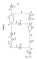
- Fig. 8 is a schematic illustration of still another alternative embodiment of the invention in which two filter zones are employed.
- The present invention is suitable for use in conjunction with both naturally aspirated and turbo-charged diesel engines of all sizes, but particularly with larger turbo-charged diesel engines utilized in heavy-duty vehicles, such as trucks, buses and the like, or in heavy industrial applications of the sort in which solid particulate emissions are especially high and especially intolerable due to poor ventilation or the like.
- The principal criterion of success with the present invention (as with all filtering systems for combustion engine emission) is the attainment of the desired radical minimization of solid particulate emission levels under conditions of steady-state operation conducive to commercial, automotive and other industrial applications. Put another way, filtering methods and apparatus which involve a filter element that irreversibly (even if gradually) clogs to a level beyond that at which the filtration is compatible with effective engine operation, or the utilization of which result in the collection of solid particulate emissions elsewhere in the system until efficient operation of the engine is foreclosed, are not capable of sufficiently long-term operation to make them feasible solutions to the pollution problems discussed hereinabove. By way of example, those of ordinary skill in the art can readily appreciate that particulate emission clogging of a filter element or trap will result in an unworkably large increase in pressure differential across the trap, thereby introducing into the system an unacceptably high backpressure so as to impede the operation of the engine itself. Accordingly, the desideratum is to achieve equilibrium, i.e., a condition in which the amount of particulate emission from the engine is equivalent to an' amount which is disposed of in a manner minimizing atmospheric pollution to the greatest degree possible. Pollution minimization in accordance with the instant invention is accomplished by returning the solid particulate matter (except for the amount which accumulates in the system itself) to the engine for combustion (incineration). Hence, design choices made in the course of implementing utilization of the invention will be geared toward maintaining the particulate emission inventory in the system at a feasibly low level and maximizing the amount of particulate emissions returned to the engine and there incinerated.
- One important point to consider is the filter element or trap which is utilized to remove solid particulate matter from the exhaust stream emitted by the engine. Suitable materials for filtering the exhaust stream in accordance with the invention are ceramic honeycomb, sintered metal particles, coated and uncoated metal mesh, ceramic fiber, ceramic foam, and packed beds. Of these, ceramic honeycomb and sintered metal particle materials act as surface filters inasmuch as particles larger than the effective pore size of the honeycomb are normally collected on its upstream surface. In contrast, the other four filter media can be considered to function as depth filters because particle removal is not limited to the surface, but is continuous throughout part or all of the filter material's thickness or depth.
- In a ceramic honeycomb filter solid particles larger than the approximate mean pore size of the material are intercepted at the material's surface and prevented from passing through the material. As particles collect on the surface, the effective pore size is reduced which, in turn, leads to an increased efficiency as smaller sized particles are collected. In general, ceramic honeycomb traps have three zones of activity: first, a period of relatively rapid back pressure increase, most likely resulting from early pore plugging and initial cake formation on the upstream surface of the filter material; second, a prolonged period- characterized by a relatively constant loading slope; finally, a shorter period during which back pressure again increases rapidly, probably due to complete plugging of many cells. Illustratively, the leading one inch or so of the filter material, when used in a typical filter assembly (see Fig. 1 or 2, described hereinafter) usually becomes more heavily loaded than does the remainder of the filter which carries only a lighter and relatively uniform film of the solid particulate filtrate. Dislodgment of trapped solid particulate matter in accordance with the invention is preferably accomplished in the first or early second stage. However, design of the ceramic honeycomb filter to optimize air flow within each channel of that filter element in order to distribute the loading more evenly does, in certain embodiments, increase the effectiveness of dislodgment and/or the time period which can be permitted to elapse between dislodgment events.
- Sintered porous metal filter materials are advantageous in that they exhibit the structural integrity, corrosion resistance and temperature resistance required in certain embodiments of the invention. These materials are made typically by precompacting and then sintering stainless steel, nickel-base and other types of alloy metal powders. They are commercially available, for instance from Mott Metallurgical Corporation, and are well-adapted to regeneration (i.e., cleaning) in accordance with the present invention. Their "re-entrainment" characteristics can be highly useful in removing trapped particles with a relative minimum of difficulty.
- In both wire mesh and ceramic fiber filter materials, the primary trapping mechanisms are impaction and diffusion. That is, during operation larger particles collide with the filaments of the mesh or fiber material and adhere to filament surfaces, or to particles already collected on those surfaces. Additionally, some smaller particles migrate by diffusion to the surface of the mesh or fiber material or to previously collected particles, and are also retained in the filter. Mesh and fiber traps of this' sort are advantageous in that the back pressures attendant upon their use are relatively low. While their tendency to , exhibit a "blowoff" phenomena - that is, a reentrainment in the exhaust stream of previously collected particles - can be somewhat disadvantageous, its controlled occurrence operates, in certain embodiments of the present invention, to the advantage of the invention's practitioner as controlled reentrainment is one of the objects of the invention. In an alternative embodiment metal mesh filter material is coated with activated alumina which provides a highly porous surface structure of large surface area. Additionally, the porous surface tends to disrupt boundary layer flow thereby encouraging diffusion to the mesh filament. The foregoing result in increased collection efficiency and holding power.
- Ceramic foam filter materials, such as silica foam materials, are also useful. These materials provide a three-dimensional, open pore network which collects solid particulate matter efficiently. The main trapping mechanisms are interception and diffusion. In general, trapping efficiency increases as the number of cells per linear inch and depth increases. Pressure drop across the ceramic foam filter increases with cell number and depth, but substantially decreases with increasing cross-sectional area for a given volumetric flow rate. Dislodgment of trapped particles in accordance with the present invention is, in many instances more difficult when employing a ceramic foam material; however, in some embodiments, this difficulty is more than offset by the decreased back pressure attendant upon use of ceramic foam material in comparison with ceramic honeycomb material, due to the fact that cell size in the ceramic foam materials is often larger than the pore size in ceramic honeycomb structures.
- Granular bed filters lend themselves to practicing of certain embodiments of the invention. They are particularly interesting for their capacity to function either in a stationary or fluidized mode. It follows that the granular bed can be operated in a stationary mode during loading or trapping to enhance collection efficiency, and then be operated in a fluidized mode during cleaning to 4 enhance dislodgment and reentrainment. This benefit is a result of the fact that penetration in a moving bed is usually significantly higher than penetration in an otherwise equivalent stationary bed, the increase being attributable to better reentrainment through mechanical agitation in the fluidized mode. In an advantageous embodiment, collection efficiency of a stationary granular bed is increased by the intergranular deposits in the bed, that is solid particles which become interstitially lodged during filtering; the bed operates as a graded media filter, larger particles typically being collected on granules at the bed's surface and smaller particles collected within the bed's pores by an increasingly dense deposit. Shallow beds are favored because they can be designed to provide high collection efficiency with relatively low back pressure and easy dislodgment and reentrainment.
- An especially preferred filter material is a ceramic honeycomb unit with parallel channels running its entire length. The cells are advantageously square in shape, but are suitably otherwise configured to be circular, elliptical, etc. The ceramic filter unit is suitably fabricated of a porous cordierite (2MgO-2Al 203-5SiO2), but is also acceptably made of any other ceramics, such as mullite, alumina, forsterite, aluminum titanate, mullite and aluminum titanate, spinel, zirconia and spinel, calcia partially stabilized zirconia, and alumina and silica. Units fabricated of the foregoing materials which are suitable for the invention typically have physical features such as cell density, porosity, mean pore size, coefficient of thermal expansion, and compression strength, corresponding to those of commercially available units of such materials employed in filtering particulate from diesel engine exhaust. The overriding requirements are that the material has the necessary mechanical strength, chemical resistance, thermofracture resistance, and melt resistance to survive effectively in the hostile environment presented by diesel engine exhaust.
- In Fig. 1 there is depicted one type of ceramic honeycomb filter unit suitable for practicing of the present invention. The
unit 10 has amonolith face 12. On the face,openings 14 alternate with solidceramic plugs 16 to form a checkerboard arrangement. The openings permit ingress to and egress from parallel channels which extend the entire length of the unit. The channels terminate at the opposite end of the unit (not shown), and are blocked at that end by ceramic plugs so as to create a set of blind passages. The opposite end of the filter unit is also made up of alternating pores and ceramic plugs. The pores in the opposite end permit ingress to and egress from a corresponding parallel set of channels running the entire length of the unit and terminating inceramic plugs 16 inface 12. Thus the ceramic channels opening at the opposite end of thefilter unit 10 provide another set of parallel blind passages, and are situated in the filter unit to alternate with the blind passages which open onface 12. - Fig. 2 schematically depicts
channel arrangement 20 of the type shown in Fig. 1. Particulateladen exhaust 22 is directed at the upstream face of theunit 24. The exhaust entersblind channels 26 throughopenings 28 in the upstream face of the unit.Channels 26 are blocked at thedownstream face 30 by ceramic plugs 32. fit thedownstream face 30,openings 34 permit ingress to and egress fromchannels 36. Those channels are closed at theupstream face 24 by ceramic plugs 38.Channels common walls 40. These common walls are sufficiently porous to permit passage of exhaust gas; however, the wall pores are sufficiently small to prevent passage of the vast majority of solid particulate matter in the exhaust. Thus, as can be seen from the arrows in Fig. 2, exhaust gas carrying solid particulate matter entersopenings 28 and passes alongchannels 26.Solid particles 42 are trapped on the walls of thechannels 26 while the gas passes through the porous walls and proceeds alongchannel 36 toopenings 34 where it is released downstream of the filter unit.Plugs 38 at theupstream face 24 of the filter unit prevent passage of the particulate laden exhaust intochannels 36 directly. Correspondingly, plugs 32 prevent escape of particulate laden exhaust at thedownstream face 30 of the unit. - In order to clean the filter unit depicted in Figs. 1 and 2, a backflush fluid pulse is passed through such unit in a direction opposite that of the aforementioned exhaust. Thus, the backflush fluid pulse first encounters what is normally
downstream end 30 of the unit, passes throughopenings 34 and intochannels 36, diffuses throughcommon walls 40, dislodgesparticles 42 from the common walls inchannels 26, entrains those particles and carries them alongchannels 26 throughopenings 28 and out of the trap. In this manner, the trap is cleaned, that is regenerated. - In certain preferred embodiments of the invention, particularly its application to automotive uses, the collection efficiency of the trap must be balanced against, and not accomplished at the expense of, excessive introduction of back pressure in the exhaust system. In such cases, it is advantageous to design the trap and associated exhaust system to maintain back pressure at as low a level as possible. Relatedly, the time period allowed to elapse between filter unit cleanings must not be so great as to permit the accumulation of a layer of solid particulate matter on the filter material surface so as to increase the pressure drop to an unacceptable level. As is readily understood by those of ordinary skill in the art, increasing the pressure drop across the filter unit is accompanied by increasing back pressure in the exhaust system. Backpressure has a direct and detrimental effect on the operation of the invention, and its occurrence should be minimized whenever possible. Pressure drop can be maintained at lower levels through the choice of appropriate design features. Illustratively, it is a function of cell geometry, wall properties and volume of a ceramic filter unit. Those features are advantageously set such that a balance is struck between minimizing pressure drop and maintaining the required filter efficiency.
- It is important to note that practicing of the instant invention frees the skilled artisan from filter design constraints which would otherwise be imposed upon him due to the use of conventional regeneration techniques. More specifically, in regeneration processing which involves burning of soot and other solid particulate matter trapped in the filter unit, the filter must be configured in order to obtain regeneration times and peak pressures which fit within desired ranges for engine and/or environmental requirements. Furthermore, in automotive applications the filter material must exhibit structural integrity for the useful lifetime of the vehicle.
- Burning collected soot off the filter places a greater physical demand on the filter than the conditions it is normally subjected to in the course of filtering exhaust. That is to say, burning of accumulated soot and other solid particulate matter during regeneration releases a large amount of energy and generates a rapid temperature rise. Moreover, that temperature rise is not necessarily evenly distributed throughout the filter unit, thereby setting up thermal gradients in both radial and axial directions. Additionally, excessive buildup of solid particulate matter can result in release of an excessively large amount of energy upon burning, thus subjecting the material (e.g. ceramic material) of the filter unit to temperatures exceeding its melting point. The quest for achievement of acceptable operating characteristics and filter life using certain conventional regeneration processing is prohibitively impeded, if not defeated, by the necessity to strike a balance among the competing considerations of filtration time between regeneration cycles, filter pressure drop, and degree of particulate loading.
- Of course, since with the instant invention regeneration is accomplished without the use of ignition of trapped solid particulate matter in the filter unit, the foregoing problems are eliminated. Attainment of the stated objective of providing method and apparatus for removal of solid particulate matter from diesel engine exhaust which are direct, simple, relatively inexpensive and highly efficient is manifest.
- Once trapped by the filter unit during exhaust flow therethrough, solid particulate matter is advantageously removed from the filter by passing a pulse of backflush fluid through the filter unit in a direction opposite to that of the exhaust flow. The concept of pulsation is understood in the art, and normally refers to the generation of one or more impulses or surges of fluid having sufficiently great power so that when the impulse or surge strikes and passes through the filter unit the particles residing in the trap are dislodged. It is a concomitant advantage of utilizing a backflush fluid pulse that the fluid also serves as a medium in which dislodged particles are entrained and carried back to the engine for incineration. Accordingly, in order for particle dislodgment to be carried out successfully in order to reduce system backpressure and renew filter efficiency, the separation forces exerted by pulsed backflush fluid must be in excess of the forces by which solid particulate matter adheres to the filter material. In addition to any direct mechanical forces that might result from flow reversal (depending on the filter material), movement of the backflush fluid stream in the immediate vicinity of trapped particulate matter is significant. Generally, in order to initiate particle movement the particle must receive energy from an external source, for instance from the impact of another particle or object or from drag forces of the moving backflush fluid stream past the exposed profile of the particle. A convenient way of looking at this phenomenon is that the backflush fluid pulse must be composed of a sufficient amount of fluid colliding with and passing through the filter unit at a sufficient velocity to dislodge trapped particles. Alternatively, the pulse can be viewed as a wave; the pulsed backflushing must be of sufficient power (i.e. a sufficient amount of energy must pass by some point in the filter per unit time) to dislodge trapped particles. Yet another way of conceptualizing this phenomenon is that the change in pressure at any one point in the filter unit due to the passage of the wave therethrough should occur in an amount of time which is sufficiently short that the fluid pulse is capable of dislodging trapped particles. It can, of course, be readily appreciated by those of ordinary skill in the art that the minimum requirements for the backflush fluid pulse to be effective in dislodging particles will vary from system to system and filter unit to filter unit depending on size, configuration and the like. However, equipped with the teachings of this application, and knowledgable of the parameters and dimensions of his particular system, the skilled artisan will be able to determine - whatever his characterization of the parameters defining the pulse - without undue experimentation the extent and magnitude of pulsed backflushing necessary to practice the instant invention (see working examples, infra).
- Pulsed backflushing fluid flow is suitably generated in any convenient manner which lends itself to utilization in the particular environment to which the invention is applied. Preliminarily, it is important to note that, while ambient air presents a convenient and highly useful backflushing fluid, the fluid is not necessarily limited to same. Alternatively, the fluid is suitably any one which can be passed through the filter material so as to dislodge trapped particles, and the presence of which does not otherwise interfere with or detrimentally affect the operation of the engine system. Oxygen, or an inert gas such as nitrogen, is an example of a suitable alternative fluid. (Of course, as will be apparent from the following, if a backflushing fluid not containing oxygen is used to dislodge the particles and transport (by means of entrainment) the particles back to the engine, then the engine is advantageously supplied with oxygen from another source in order that combustion be optimized.)
- In an especially advantageous embodiment of the invention, the backflush fluid pulse is generated by inducing a vacuum condition, or at least very low pressure, in the exhaust system on the upstream side of the trap, and then effecting a sudden release of backflush fluid into the vacuum or low pressure volume such that a sufficient mass of the backflush fluid rushes through the trap at high velocity (in a short time period) to dislodge trapped particles. An especially advantageous manner for accomplishing this is to employ the intake pull of the engine to draw down the pressure on the upstream side of trap or filter unit. A valve in the exhaust system is actuated, and moved into the open position, in response to the attainment of a suitably low pressure; the valve's opening causes ambient air or other backflushing fluid to be drawn through the filter unit or trap in a direction opposite to that of the exhaust flow (the exhaust flow has of course been interrupted during this backflushing cycle) by the low pressure conditions on the upstream side of the filter unit or trap.
- Alternatively, the backflush fluid pulse can be a burst or surge of pressurized fluid, for instance compressed gas (illustratively, air). The pulse is acceptably drawn from a pressurized container or other suitable source; conveniently compressed air drawn from the hydraulic or turbo-charging system of a diesel-powered vehicle will do. The compressed gas pulse is injected into the exhaust system on the downstream side of the filter unit or trap so as to flow through the trap in a direction which is the reverse of that taken by the exhaust flow during normal filtering operations. Again, the compressed gas pulse is injected into the system during interruption of normal exhaust flow. The compressed gas pulse must be of sufficient mass and traveling at sufficient velocity to dislodge the particles trapped in the filter unit.
- With_the foregoing examples in mind, it is readily appreciable to the skilled artisan that any other suitable manner of drawing or forcing pulsed backflush fluid through the trap in a direction opposite to that taken by the exhaust flow can be utilized, the principal criteria of selection being only that the means employed is sufficient to dislodge trapped particles and it does not unduly interfere with the engine's operation.
- In addition to providing a means for dislodging trapped particles from the filter unit for purposes of cleaning same, it is necessary in accordance with the present invention to transport those particles back to the diesel engine for incineration. This is typically accomplished by entraining the particles in a fluid stream conducted through a line of the exhaust system leading to the engine's air intake port. After initial dislodgment, the dislodged particles are in very short order brought under the influence of the flow of the aforementioned fluid stream. That flow must be sufficient to maintain "floatation", that is, keep the particles free from recapture by the trap or filter unit, until they leave the unit. Recapture is disadvantageous in that it lowers the efficiency of the regeneration operation during the cleaning cycle.
- In an advantageous refinement of the present invention the backflush fluid pulse employed to dislodge trapped solid particulate matter is also utilized as an entrainment vehicle, i.e. a carrier, for the dislodged particulate matter in order to transport same back to the diesel engine. Typically, the backflush fluid pulse is air, the oxygen component of which is sufficient, upon reaching the engine along with the particles entrained in the air, to enable the incineration (oxidation) of those particles.
- Further objects and features of the invention will be apparent from the following examples Example 1
- A diesel engine
exhaust filtering arrangement 60 as schematically depicted in Fig. 3 was constructed to demonstrate the invention. AMack diesel engine 62 having a solid particulate emission level of about 1 gm/min. under normal steady-state operational conditions was connected bylines trap 64. The trap was a ceramic filter having a single filter zone which was positioned i across the engine's exhaust stream flowing throughlines Lines main exhaust line 74 leading to the atmosphere.Line 78 was connected between the engine's exhaust port andmain exhaust line 74.Intake line 76 conducted air from the ambient atmosphere to theengine 62.Line 68 connected the upstream side of thetrap 64 and theintake line 76. -
Valve 80 was positioned acrossline 66 at a location intermediate the port from which exhaust is emitted from the engine andline 66's connection withline 68. The valve was movable between an open state permitting flow throughline 66 and a closed state interrupting flow. -
Valve 82 was positioned acrossline 72 betweenmain exhaust line 74 and the connection ofline 70 withline 72. This valve too was movable between an open state permitting flow throughline 72 and a closed state interrupting flow. -
Valve 84 was positioned acrossline 78 betweenmain exhaust line 74 and the connection betweenlines line 78 and a closed state interrupting flow. -
Valve 86 was positioned acrossintake line 76, and was movable between an open state permitting flow throughline 76 and a closed state interrupting flow along said intake path. -
Valve 88 was positioned acrossline 68, and was movable between an open state permitting flow throughline 68 and a closed state interrupting flow. - An
aluminum foil diaphragm 92 was positioned across the end ofline 70. The thickness and strength of the foil diaphragm were selected so that it would rupture when one side of it was subjected to atmospheric pressure and the other side to a reduced pressure condition resulting from the intake pull of the engine. -
Valve 90 was positioned acrossline 70 betweendiaphragm 92 and the connection of theline 70 withline 72. The valve was movable between an open state permitting flow throughline 70 and a closed state interrupting flow. - Sampler 94 (an isokinetic sampler) was connected to line 78 for the purpose of obtaining a profile of solid particulate emission from the engine before and during pulsed backflushing. Sampler 96 (also an isokinetic sampler) was connected to line 70 for the purpose of ascertaining the amount of solid particulate matter passing through
trap 64, and thus into the atmosphere.Pressure sensor 98 was connected to line 68 for the purpose of determining when a pressure rise (signalling the passage of a backflush fluid pulse on its way to engine 62) occurred in the line. - In operation of the engine, for periods of approximately 10
minutes valves line 76, and exhaust flow from the engine throughlines trap 64,lines main exhaust line 74.Valves - Typically, after a ten-minute cycle during which' exhaust was passed through
trap 64,valves valves line 78. After ten to twenty seconds,valve 90 was opened, and thenvalve 86 closed, the engine's intake pull thus being redirected throughline 68,trap 64 andline 70. The intake pull of the engine drew down the pressure inlines foil 92 ruptured. That rupture caused a pulse of ambient air to be pulled throughline 70,trap 64,line 68 andline 76, intoengine 62. When the pulse passed through the trap it dislodged solid particulate matter therein. The particulate was entrained in the backflush air pulse and also carried to theengine 62. Whensensor 98 ascertained passage of the pulse inline 68, a signal was generated (by conventional means not shown for simplicity) in response to which the valves were returned to their normally open and closed states (as described in the preceding paragraph). - The system was operated for approximately 1040 minutes during which 100 cycles were completed, the cycles generally comprising about 10 minutes of passage of the engine's exhaust through
trap 64 and then about ten to twenty seconds during which exhaust was redirected throughline 78 and ultimately the trap was cleaned by a backflushing pulse of ambient air. - From measurements taken with
sampler 96 during passage of the engine's exhaust throughtrap 64, it was found that the trap was 93 to 96 percent effective in filtering out solid particulate emission. Furthermore, monitoring of the pressure differential acrosstrap 64 during operation of the exhaust filtering system showed that regeneration by pulsed backflushing is highly effective in restoring acceptable pressure drop characteristics to the trap while maintaining suitable filtering efficiency. More specifically, as can be seen from the plot of time versus upstream pressure (backpressure) (represented by "o") and pressure differential across the trap (represented by "x") which appears in Fig. 4 - an excerpt, forminutes 140 to 230, of the strip chart recordation of pressure readings for the trap during the entire 1040 minutes of operation - the pattern which emerged as typical of trap regeneration was as follows. Over a set of perhaps five to nine cycles, upstream pressure (engine backpressure) and differential pressure would increase somewhat during each (approximately) ten-minute period of exhaust filtration (pulsed backflushing is represented on the strip chart by the portions of the curve at which pressure drops precipitously). Over the course of several cycles the maximum backpressure and pressure differential reached during each succeeding cycle would generally be higher than the last, until one backflushing pulse would dislodge an unusually large number of particles and thus be particularly effective in cleaning the filter and restoring a low pressure differential. A recurrent pattern of such behavior indicates the attainment of a steady-state condition in which the system is not gradually deteriorating due to gradually increasing and irreversible filter loading, but rather is continually regenerated so as to remain in an equilibrated and effective state such that filtration can be continued indefinitely. - In addition, it was calculated based on data obtained through the use of
isokinetic sampler 94, that the amount of solid particulate matter being released into the atmosphere when employing the above-described experimental system was at most forty percent (i.e., about four grams every ten minutes) of that which would have been released into the atmosphere by the engine (about ten grams every ten minutes) had the exhaust not been filtered. Inasmuch as this condition was observed to hold over a long period of operation during which the engine produced several hundred grams of solid particulate emission, it is clear that the system reached a steady-state condition in which the majority of the solid particulate emission was being incinerated upon its return to the engine. This establishes the clear advantages and benefits of the present invention. - Moreover, in interpreting the data obtained in the aforementioned example, it must be realized that the efficiency of the system was deliberately decreased by releasing unfiltered engine exhaust into the atmosphere for a periods of up to twenty seconds, i.e., through
line 78 whilevalve 84 was open, in order to measure the amount of solid particulate matter being emitted by the engine before and during regeneration (with isokinetic sampler 94). It can readily be appreciated that elimination of this procedure (which is unnecessary except for experimentation) would increase to an even greater extent the efficiency of the present invention in filtering solid particulate emission from diesel engine exhaust. - Yet another factor also merits attention. Because of the fact that, during the
time valve 86 is closed and beforefoil 92 ruptures the air supply to the engine is reduced, while provision of fuel thereto is not abated, the output of uncombusted carbon from the engine during that time is increased significantly. Of course, with the experimental set-up described above, this increased output occurs during the time thatvalve 84 is open, and thus the increased solid particulate output is passed unfiltered throughline 78 and into the atmosphere. Accordingly, the actual solid particulate emission from the diesel engine is greater than the 1 g./min. figure assumed for the above-mentioned calculations; the divisor should thus have been greater than 1 g./min. It follows that the percent of solid matter emitted (quotient) actually was smaller than forty percent. It also follows that the experimental system was more than sixty percent effective in reducing solid particulate emission. - Of course, in preferred embodiments of the invention which lend themselves to commercial application, engine exhaust would not be released directly into the atmosphere for any substantial period of time, if at all, and thus filtration efficiency should be greatly improved. This is, in fact, the case, as shown by following Example 2.
- Fig. 5 is a schematic depiction of a diesel engine exhaust
emission filtration system 100 actually constructed, to demonstrate the invention. - A
Cummins diesel engine 102, having a solid particulate emission level of about 1.1 g/min. was connected bylines trap 104. The trap was a ceramic filter (the same filter unit is employed for example 1) having a single filter zone which was positioned across the engine's exhaust stream flowing throughlines - The downstream end of
trap 104 and line 110 were connected to provide a direct path to the atmosphere.Intake line 112 was connected to theengine 102 and conducted air from the ambient atmosphere to the engine.Line 108 was connected between the upstream side oftrap 104 and theintake line 112.Valve 114 was positioned acrossline 108, and was movable between an open state permitting flow throughline 108 and a closed state interrupting flow.Valve 116 was positioned acrossintake line 112, and was movable between an open state permitting flow through that line and a closed state interrupting flow. - An
aluminum foil diaphragm 118 was positioned acrossline 108 betweenvalve 114 and the connection oflines - In operation, the engine was run for 91 cycles of the type described in connection with example 1 - i.e., each cycle comprising a relatively long period during which the engine's exhaust was directed through the trap 104 (usually about ten minutes but sometimes up to one-half an hour or more) and a shorter period (about .2 seconds) during which exhaust flow through the trap was interrupted to accommodate regeneration. During the longer period,
valve 116 was maintained in the opened state andvalve 114 was maintained in the closed state, thereby causing the engine's exhaust to flow throughlines trap ' 104, through the trap and through line 110 for release into the atmosphere. To regenerate the trap,valve 114 was opened andvalve 116 closed, the engine's intake pull thus being redirected throughline 108. The intake pull of the engine drew down the pressure inline 108, and when sufficiently low pressure was achieved thefoil 118 ruptured. The rupture caused a pulse of ambient air to be pulled through line 110,trap 104, andlines engine 102. When the pulse passed through the trap it dislodged solid particulate matter therein. The particulate was entrained in the backflush air pulse and also carried toengine 102. - Sampler 122 (isokinetic sampler) was connected to line 110 for the purpose of ascertaining the amount of solid particulate matter passing through
trap 104, and thus into the atmosphere. Sensor 12.0 (a pressure sensor) was connected toline 108 for the purpose of determining when a pressure rise (signaling the passage of a backflush fluid pulse on its way to engine 102) occurred in the line. Whensensor 120 ascertained passage of the pulse inline 108, a signal was generated (by conventional means not shown for the sake of simplicity) in response to which the valves were returned to their normally opened and closed states. - During the first several runs of the the above-described exhaust filtration system the fresh ceramic cordierite trap was being broken in, i.e., the trap was equilibrating. Over the course of those cycles the upstream pressure from one cycle to the next gradually rose from about 2.1 inches of mercury up to about 3.5 inches of mercury. In subsequent runs, equilibrium had been attained and the upstream pressure varied from about 3.4 to about 4 inches of mercury in a recurring pattern as described for the trap of example 1. (It can be readily appreciated that the reported pressures were the result of trap size and can be changed as a matter of design.) Additionally, because (in contrast to the embodiment of Example 1) the embodiment of this example did not release unfiltered exhaust to the atmosphere, the observed emission was even more radically reduced. It is noteworthy that during the running of the Example 1 system, a puff of black smoke was observed to emerge from the main exhaust line, corresponding to the release of unfiltered exhaust during the ten to twenty second period in which regeneration was accomplished. Since exhaust was not released directly to the atmosphere in example 2, but instead held in the system (in line 106) until the interruption for regeneration was completed, no such puff of black smoke was emitted from main exhaust line 110.
-
Sampler 122 indicated thattrap 104 was effective in removing 93 to 96% of solid particulate emission from the filtered exhaust during the first 54 cycles. Since solid particulate emission is not released from the system in any other manner, it is clear that the system was at least 90% effective in removing solid particulate emission from diesel engine exhaust. In succeeding runs trap efficiency decreased to about 85%; this was viewed as an aberration of the trap material itself and not of the invention. Accordingly, later results can be discounted. However, even including those questionable data, the average filtering efficiency was at least 88.9% on average. - Yet another embodiment suitable for commercial application is illustrated in Fig. 6. A diesel engine 130 is connected to trap 132 by
line 134.Intake line 136 leads from the ambient atmosphere to engine 130, to provide ambient air for combustion within the engine.Line 138 is connected toline 134 and toline 136 to provide an alternate flow path around the engine.Valve 140 is positioned acrossline 136, and is movable from an open position permitting flow through the line, to a closed position interrupting flow.Valve 142 is positioned acrossline 134, and is movable between an open position permitting flow through the line and a closed position preventing such flow.Line 138 is connected to line 136 betweenvalve 140 and the engine, and is connected to line 134 betweenvalve 142 an thetrap 132. The pressure drop acrosstrap 132 is monitored by a conventional sensor (not shown for the sake' of simplicity) sensor. When the pressure drop across the exhaust filter reaches a predetermined value,valves 140 and 142 - which are normally open to permit intake flow to the engine and transportation of the exhaust stream to the trap for filtration - are closed simultaneously. This can be accomplished by actuating a solenoid on each valve by means of a differential pressure switch placed across the filter.Valve 144 is positioned acrossline 138, and is movable between an open position permitting flow through line and a closed position preventing flow. Whenvalves valve 144. During this time, exhaust from the engine is accumulated in the volume of line between the engine andvalve 142. -
Valve 144 is an automatic valve that opens when the pressure differential across it reaches a predetermined value. Whenvalve 144 opens in response to the drawing down of pressure by the engine in line 138 (valve 144 opens very I quickly) ambient air flows throughline 146,trap 132,line 134line 138 andline 136, and eventually to the engine, in a direction opposite that of normal exhaust flow. This surge of gas constitutes a pulsed backflushing oftrap 132, which surge carries particles dislodged from the trap back to the engine for incineration. -
Valves valve 144's automatic opening, after a suitable delay.Valve 144 automatically closes after the pressure differential across it is removed, and the system is restored to its original condition. The entire cleaning sequence is completed in less than one second, and preferably less than 0.25 seconds. Indeed, regeneration periods of no more than one second, and preferably no more than 0.25 seconds, are advantageously employed in many other embodiments of the invention also. - It can readily be appreciated that the systems of Examples 1 and 2, especially that of Example 2, can be modified by appropriate substitution of automatic valve sequencing as described in connection with the embodiment depicted in Fig. 6. This would of course eliminate the necessity of using a foil diaphragm, which is an expedient adopted for experimentation only. It is also clear that, due to the benefits deriving from pulsed backflushing, the filter means of the claimed invention need not be limited to only one filter zone. Several of those advantages accrue even when two or more filter elements (or two or more filter zones of one element) are employed, although use of only one filter zone affords clear commercial advantages.
- Yet another embodiment is illustrated in Fig. 7. A filtered
system 150 includesdiesel engine 152 connected to trap 154 byline 156. Intake line 158 leads from the ambient atmosphere toengine 152, to provide ambient air for combustion within the engine.Line 160 is connected toline 156 and to line 158 to provide an alternate flow path around the engine.Valve 162 is positioned across line 158, and is movable from an open position permitting flow through the line, to a closed position interrupting flow.Valve 164 is positioned acrossline 156, and is movable between an open position permitting flow through the line and a closed position preventing such flow.Line 160 is connected to line 158 betweenvalve 162 andengine 152, and is connected to line 156 betweenvalve 164 andtrap 154. The pressure drop acrosstrap 154 is monitored by a conventional sensor (not shown for the sake of simplicity). When the pressure drop acrosstrap 154 reaches a predetermined value,valves 162 and 164 - which are normally open to permit intake flow to the engine and transportation of the exhaust stream to the trap for filtration - are closed simultaneously. This can be accomplished by actuating a solenoid on each valve by means of a differential pressure switch placed across the filter. After a suitable but short delay a pulse of compressed air is released fromsource 170 and injected throughline 168 intoline 166, throughtrap 154 andlines engine 152. This surge of air constitutes a pulsed backflushing oftrap 154, which surge carries particles dislodged from the trap back to the engine for incineration. - During this time, exhaust from the engine is accumulated in the volume of line between the engine and
valve 164. -
Valves - A still further embodiment of the invention is illustrated in Fig. 8. A filtered
system 180 includesdiesel engine 182 connected alternately to trap 184 bylines lines 192 and 202.Intake line 188 leads from the ambient atmosphere toengine 182, to provide ambient air for combustion within the engine;valve 190 is positioned acrossline 188 and is movable between open and closed states permitting and interrupting flow, respectively.Line 194 is connected toline 188 and to line 202 to provide an alternate flow path around the engine.Line 192 connects withvalve 214, and is movable to direct flow into eitherline 198 or 202 while closing off flow to the other.Line 200 connects tovalve 212, which is movable to direct flow from eitherline 198 or 204 intoline 200, and to close off flow from the line not selected.Line 194 is connected to line 188 betweenvalve 190 and the engine. The pressure drop acrosstraps 184 and 186 is monitored by conventional sensors (not shown for the sake of simplicity). - Assume trap 184 is filtering exhaust. When the pressure drop across traps 184 reaches a predetermined value,
valves 214 and 212 - which have been oriented to permit transportation of the exhaust stream to trap 184 for filtration and drawing of air throughtrap 186,lines line 188 back to the engine - are moved simultaneously. The system is then set so that exhaust flows throughlines 192 and 202 totrap 186, and then intoline 208 to the atmosphere while flow from the atmosphere through trap 184,lines line 188 back to the engine is permitted. Periodicallyvalve 190 is closed.Valve 210 is positioned acrossline 200, and is movable between an open position permitting flow through line and a closed position preventing flow. Whenvalve 190 is closed the engine quickly reduces the pressure in the volume of line between the engine andvalve 210, which is normally closed. -
Valve 210 is an automatic valve that opens when the pressure differential across it reaches a predetermined value. Whenvalve 210 opens in response to the drawing down of pressure by the engine in line 194 (valve 210 opens very quickly) ambient air flows throughline 206, trap 184,line 198,line 200 andline 194, and eventually (through line 188) to the engine. This surge of gas constitutes a pulsed backflushing of trap 184, which surge carries particles dislodged from the trap back to the engine for incineration. - When
valve 190 is opened,valve 210 automatically closes after the pressure differential across it is removed, and the system is restored to its initial condition. The entire cleaning sequence is completed in less than one second, and preferably less than 0.25 seconds. In some embodiments each trap is cleaned by a plurality of such sequences. Whentrap 186 needs regeneration,valves trap 186 in like manner. It can be readily appreciated from the foregoing example that numerous alternative systems containing a plurality of filter zones are configurable depending on the needs of the practitioner and his environmental constraints. - The terms and expressions which have been employed are used as terms of description and not of limitation, and there is no intention in the use of such terms and expressions of excluding any equivalents of the features shown and described or portions thereof, its being recognized that various modifications are possible within the scope of the invention. Thus, it can readily be appreciated that the invention is not limited to dislodgment of particles from the filter unit by means of a pulse of backflushing fluid. Rather, any mechanical wave which is of sufficient power to effect dislodgment of solid particulate matter trapped in the filter unit, and which can feasibly be employed in the particular application to which the invention is put, is suitable for practice of the invention'. For instance, in certain embodiments of the invention the particles are acceptably dislodged from the filter unit by a sonic wave generated by appropriate conventional apparatus. The principal and basic criterion for such mechanical waves are that the filter unit must be subjected to a wave of sufficient power, that is of sufficiently high energy passing by any point within the filter unit in a selected unit of time, to dislodge the trapped particulate material. Waves which fulfill this requirement are suitable.
- In accordance with the foregoing, a method and apparatus are provided which enable direct, simple, relatively inexpensive and-efficient filtration of diesel engine exhaust to remove solid particulate matter. More specifically, the present method and apparatus embodiments result in a reduction of solid particulate emission levels in diesel engine exhaust to an insignificant level, i.e., filtering out of 90% or more of the particulate. Thus, the present invention obviates the need for deliberate suppression of engine power, or reliance on other disadvantageous conventional filtration techniques, in order to reduce solid particulate exhaust emission. The attainment of effective filtration of solid particulate matter from diesel engine exhaust along with a significantly increased utilization of the diesel engine's potential power output is a substantial advance in the art.
Claims (35)
Priority Applications (1)
| Application Number | Priority Date | Filing Date | Title |
|---|---|---|---|
| AT86301517T ATE79158T1 (en) | 1985-03-05 | 1986-03-04 | METHOD AND APPARATUS FOR FILTERING SOLID PARTICLES FROM A DIESEL ENGINE EXHAUST. |
Applications Claiming Priority (2)
| Application Number | Priority Date | Filing Date | Title |
|---|---|---|---|
| US70826085A | 1985-03-05 | 1985-03-05 | |
| US708260 | 1991-05-28 |
Publications (2)
| Publication Number | Publication Date |
|---|---|
| EP0194131A1 true EP0194131A1 (en) | 1986-09-10 |
| EP0194131B1 EP0194131B1 (en) | 1992-08-05 |
Family
ID=24845062
Family Applications (1)
| Application Number | Title | Priority Date | Filing Date |
|---|---|---|---|
| EP86301517A Expired - Lifetime EP0194131B1 (en) | 1985-03-05 | 1986-03-04 | Method and apparatus for filtering solid particulate matter from diesel engine exhaust |
Country Status (9)
| Country | Link |
|---|---|
| EP (1) | EP0194131B1 (en) |
| JP (1) | JPS61268813A (en) |
| KR (1) | KR860007456A (en) |
| AT (1) | ATE79158T1 (en) |
| AU (1) | AU5430386A (en) |
| BR (1) | BR8600932A (en) |
| CA (1) | CA1287532C (en) |
| DE (1) | DE3686278T2 (en) |
| ZA (1) | ZA861609B (en) |
Cited By (11)
| Publication number | Priority date | Publication date | Assignee | Title |
|---|---|---|---|---|
| EP0230140A1 (en) * | 1986-01-06 | 1987-07-29 | BREHK Ventures | An improved method and apparatus for filtering solid particulate matter from diesel engine exhaust |
| EP0308972A2 (en) * | 1987-09-25 | 1989-03-29 | Asahi Glass Company Ltd. | Apparatus and method for treating an exhaust gas from a diesel engine |
| GB2218008A (en) * | 1988-05-06 | 1989-11-08 | Ford Motor Co | Cleaning exhaust gas |
| US5228891A (en) * | 1992-01-07 | 1993-07-20 | Pall Corporation | Regenerable diesel exhaust filter |
| US5457945A (en) * | 1992-01-07 | 1995-10-17 | Pall Corporation | Regenerable diesel exhaust filter and heater |
| US5470364A (en) * | 1992-01-07 | 1995-11-28 | Pall Corporation | Regenerable diesel exhaust filter |
| EP1455059A1 (en) * | 2003-03-03 | 2004-09-08 | J. Eberspächer GmbH & Co. | Method and Device for Cleaning a Particulate Filter |
| KR100495204B1 (en) * | 2000-03-29 | 2005-06-14 | 도요타지도샤가부시키가이샤 | Exhaust gas cleaning device for internal combustion engines |
| US8789360B2 (en) | 2011-10-26 | 2014-07-29 | Boshart Automotive Testing Services, Inc. | Over temperature/pressure safety device for diesel particulate filters |
| KR102308530B1 (en) * | 2021-07-07 | 2021-10-06 | 주식회사 고산자 | Survey system for underground facility using drone |
| CN117249507A (en) * | 2023-11-16 | 2023-12-19 | 广东汇绿实验室设备科技有限公司 | Sterile ventilation equipment in laboratory |
Families Citing this family (8)
| Publication number | Priority date | Publication date | Assignee | Title |
|---|---|---|---|---|
| JPH02185611A (en) * | 1989-01-10 | 1990-07-20 | Asahi Glass Co Ltd | Exhaust black smoke removing device |
| US5253476A (en) * | 1992-02-21 | 1993-10-19 | Northeastern University | Pulsed, reverse-flow, regenerated diesel trap capturing soot, ash and PAH's |
| US5426936A (en) * | 1992-02-21 | 1995-06-27 | Northeastern University | Diesel engine exhaust gas recirculation system for NOx control incorporating a compressed air regenerative particulate control system |
| SE516061C2 (en) * | 2000-06-09 | 2001-11-12 | Volvo Lastvagnar Ab | Arrangement and method for cleaning particle filters with the aid of a tone generator |
| DE10312995B4 (en) * | 2003-03-03 | 2011-12-15 | J. Eberspächer GmbH & Co. KG | Method and device for cleaning a particulate filter |
| JP4954010B2 (en) * | 2007-10-01 | 2012-06-13 | Udトラックス株式会社 | Engine exhaust purification system |
| DE102009024535A1 (en) | 2009-06-10 | 2010-12-16 | J. Eberspächer GmbH & Co. KG | exhaust aftertreatment device |
| JP5318180B2 (en) * | 2011-11-17 | 2013-10-16 | Udトラックス株式会社 | Engine exhaust purification system |
Citations (5)
| Publication number | Priority date | Publication date | Assignee | Title |
|---|---|---|---|---|
| DE664371C (en) * | 1934-09-15 | 1938-08-25 | Auergesellschaft Akt Ges | Exhaust filter for internal combustion engines |
| US3397682A (en) * | 1966-11-25 | 1968-08-20 | Homer D. Riggan | Apparatus for exhaust gas separation |
| GB2097283A (en) * | 1981-04-03 | 1982-11-03 | Ricardo Consulting Eng | Filter arrangements for the exhausts of IC engines |
| US4464185A (en) * | 1981-03-07 | 1984-08-07 | Nippon Soken, Inc. | Exhaust gas filter |
| FR2543216A1 (en) * | 1983-03-25 | 1984-09-28 | Bosch Gmbh Robert | Arrangement removes solid particles from exhaust gases |
-
1986
- 1986-03-04 KR KR1019860001499A patent/KR860007456A/en not_active Application Discontinuation
- 1986-03-04 JP JP61047176A patent/JPS61268813A/en active Pending
- 1986-03-04 AT AT86301517T patent/ATE79158T1/en not_active IP Right Cessation
- 1986-03-04 BR BR8600932A patent/BR8600932A/en unknown
- 1986-03-04 EP EP86301517A patent/EP0194131B1/en not_active Expired - Lifetime
- 1986-03-04 CA CA000503207A patent/CA1287532C/en not_active Expired - Fee Related
- 1986-03-04 ZA ZA861609A patent/ZA861609B/en unknown
- 1986-03-04 DE DE8686301517T patent/DE3686278T2/en not_active Expired - Fee Related
- 1986-03-05 AU AU54303/86A patent/AU5430386A/en not_active Abandoned
Patent Citations (5)
| Publication number | Priority date | Publication date | Assignee | Title |
|---|---|---|---|---|
| DE664371C (en) * | 1934-09-15 | 1938-08-25 | Auergesellschaft Akt Ges | Exhaust filter for internal combustion engines |
| US3397682A (en) * | 1966-11-25 | 1968-08-20 | Homer D. Riggan | Apparatus for exhaust gas separation |
| US4464185A (en) * | 1981-03-07 | 1984-08-07 | Nippon Soken, Inc. | Exhaust gas filter |
| GB2097283A (en) * | 1981-04-03 | 1982-11-03 | Ricardo Consulting Eng | Filter arrangements for the exhausts of IC engines |
| FR2543216A1 (en) * | 1983-03-25 | 1984-09-28 | Bosch Gmbh Robert | Arrangement removes solid particles from exhaust gases |
Non-Patent Citations (1)
| Title |
|---|
| PATENTS ABSTRACTS OF JAPAN, vol. 8, no. 189 (M-321) [1626], 30th August 1984; & JP - A - 59 79 022 (MITSUBISHI JIDOSHA KOGYO K.K.) 08-05-1984 * |
Cited By (13)
| Publication number | Priority date | Publication date | Assignee | Title |
|---|---|---|---|---|
| EP0230140A1 (en) * | 1986-01-06 | 1987-07-29 | BREHK Ventures | An improved method and apparatus for filtering solid particulate matter from diesel engine exhaust |
| EP0308972A2 (en) * | 1987-09-25 | 1989-03-29 | Asahi Glass Company Ltd. | Apparatus and method for treating an exhaust gas from a diesel engine |
| EP0308972A3 (en) * | 1987-09-25 | 1990-05-16 | Asahi Glass Company Ltd. | Apparatus and method for treating an exhaust gas from a diesel engine |
| GB2218008A (en) * | 1988-05-06 | 1989-11-08 | Ford Motor Co | Cleaning exhaust gas |
| US5470364A (en) * | 1992-01-07 | 1995-11-28 | Pall Corporation | Regenerable diesel exhaust filter |
| US5457945A (en) * | 1992-01-07 | 1995-10-17 | Pall Corporation | Regenerable diesel exhaust filter and heater |
| US5228891A (en) * | 1992-01-07 | 1993-07-20 | Pall Corporation | Regenerable diesel exhaust filter |
| KR100495204B1 (en) * | 2000-03-29 | 2005-06-14 | 도요타지도샤가부시키가이샤 | Exhaust gas cleaning device for internal combustion engines |
| EP1455059A1 (en) * | 2003-03-03 | 2004-09-08 | J. Eberspächer GmbH & Co. | Method and Device for Cleaning a Particulate Filter |
| US8789360B2 (en) | 2011-10-26 | 2014-07-29 | Boshart Automotive Testing Services, Inc. | Over temperature/pressure safety device for diesel particulate filters |
| KR102308530B1 (en) * | 2021-07-07 | 2021-10-06 | 주식회사 고산자 | Survey system for underground facility using drone |
| CN117249507A (en) * | 2023-11-16 | 2023-12-19 | 广东汇绿实验室设备科技有限公司 | Sterile ventilation equipment in laboratory |
| CN117249507B (en) * | 2023-11-16 | 2024-03-19 | 广东汇绿实验室设备科技有限公司 | Sterile ventilation equipment in laboratory |
Also Published As
| Publication number | Publication date |
|---|---|
| CA1287532C (en) | 1991-08-13 |
| DE3686278T2 (en) | 1993-03-18 |
| JPS61268813A (en) | 1986-11-28 |
| ATE79158T1 (en) | 1992-08-15 |
| BR8600932A (en) | 1986-11-11 |
| AU5430386A (en) | 1986-09-11 |
| EP0194131B1 (en) | 1992-08-05 |
| ZA861609B (en) | 1986-10-29 |
| KR860007456A (en) | 1986-10-13 |
| DE3686278D1 (en) | 1992-09-10 |
Similar Documents
| Publication | Publication Date | Title |
|---|---|---|
| US4864821A (en) | Method and apparatus for filtering solid particulate matter from diesel engine exhaust | |
| US5123243A (en) | Method and apparatus for trapping and incinerating particulate matter found in diesel engine exhaust | |
| EP0194131B1 (en) | Method and apparatus for filtering solid particulate matter from diesel engine exhaust | |
| JP3288536B2 (en) | Exhaust gas filter and exhaust gas treatment device using the same | |
| AU2003252127B2 (en) | System and method for reducting pollutants from diesel engine exhaust | |
| RU2260469C2 (en) | Trap for solid particles and method of separation of solid particles from fluid medium flow | |
| US7273514B2 (en) | Apparatus and method for filtering particulate and NOx emissions | |
| JP4055710B2 (en) | Diesel exhaust gas purification filter | |
| KR100595407B1 (en) | Particulate matter reducing apparatus | |
| US7524360B2 (en) | Method and apparatus for filtering exhaust particulates | |
| KR100605005B1 (en) | Catalytic soot filter and use thereof in treatment of lean exhaust gases | |
| JPH0882257A (en) | Exhaust gas recirculating device for internal combustion engine | |
| EP1262641B1 (en) | Carbon particle reducing apparatus | |
| JP2013507564A (en) | How to operate the particulate filter | |
| JPH07189655A (en) | Exhaust emission control device for engine | |
| Guo et al. | Performance of a catalyzed diesel particulate filter system during soot accumulation and regeneration | |
| JP4567968B2 (en) | Exhaust gas purification device and exhaust gas purification method | |
| Ichikawa et al. | Development of wall-flow type diesel particulate filter system with efficient reverse pulse air regeneration | |
| JPS61135917A (en) | Exhaust gas fine particles purifying device for diesel engine | |
| Kim et al. | Design of a diesel particulate trap-incinerator with simultaneous filtration and compressed air regeneration (CAR) | |
| Vora et al. | Diesel Particulate Filter | |
| Matsunuma et al. | Status of particulate trap system for a heavy duty diesel truck | |
| JPH09228823A (en) | High temperature dust collector | |
| JP2005188507A (en) | Exhaust emission control device and exhaust emission control method for diesel engine | |
| Kasai et al. | New Cordierite Diesel Particulate Filter Material for the Diesel Particulate-NOx Reduction System. |
Legal Events
| Date | Code | Title | Description |
|---|---|---|---|
| PUAI | Public reference made under article 153(3) epc to a published international application that has entered the european phase |
Free format text: ORIGINAL CODE: 0009012 |
|
| AK | Designated contracting states |
Kind code of ref document: A1 Designated state(s): AT BE CH DE FR GB IT LI LU NL SE |
|
| 17P | Request for examination filed |
Effective date: 19870309 |
|
| 17Q | First examination report despatched |
Effective date: 19871116 |
|
| GRAA | (expected) grant |
Free format text: ORIGINAL CODE: 0009210 |
|
| AK | Designated contracting states |
Kind code of ref document: B1 Designated state(s): AT BE CH DE FR GB IT LI LU NL SE |
|
| PG25 | Lapsed in a contracting state [announced via postgrant information from national office to epo] |
Ref country code: NL Effective date: 19920805 Ref country code: LI Effective date: 19920805 Ref country code: CH Effective date: 19920805 Ref country code: BE Effective date: 19920805 Ref country code: AT Effective date: 19920805 |
|
| REF | Corresponds to: |
Ref document number: 79158 Country of ref document: AT Date of ref document: 19920815 Kind code of ref document: T |
|
| REF | Corresponds to: |
Ref document number: 3686278 Country of ref document: DE Date of ref document: 19920910 |
|
| ITF | It: translation for a ep patent filed |
Owner name: ING. A. GIAMBROCONO & C |
|
| REG | Reference to a national code |
Ref country code: CH Ref legal event code: PL |
|
| ET | Fr: translation filed | ||
| NLV1 | Nl: lapsed or annulled due to failure to fulfill the requirements of art. 29p and 29m of the patents act | ||
| PG25 | Lapsed in a contracting state [announced via postgrant information from national office to epo] |
Ref country code: GB Effective date: 19930304 |
|
| PG25 | Lapsed in a contracting state [announced via postgrant information from national office to epo] |
Ref country code: SE Effective date: 19930305 |
|
| PG25 | Lapsed in a contracting state [announced via postgrant information from national office to epo] |
Ref country code: LU Free format text: LAPSE BECAUSE OF NON-PAYMENT OF DUE FEES Effective date: 19930331 |
|
| PLBE | No opposition filed within time limit |
Free format text: ORIGINAL CODE: 0009261 |
|
| STAA | Information on the status of an ep patent application or granted ep patent |
Free format text: STATUS: NO OPPOSITION FILED WITHIN TIME LIMIT |
|
| 26N | No opposition filed | ||
| GBPC | Gb: european patent ceased through non-payment of renewal fee |
Effective date: 19930304 |
|
| PG25 | Lapsed in a contracting state [announced via postgrant information from national office to epo] |
Ref country code: FR Effective date: 19931130 |
|
| PG25 | Lapsed in a contracting state [announced via postgrant information from national office to epo] |
Ref country code: DE Effective date: 19931201 |
|
| REG | Reference to a national code |
Ref country code: FR Ref legal event code: ST |
|
| EUG | Se: european patent has lapsed |
Ref document number: 86301517.8 Effective date: 19931008 |
|
| PG25 | Lapsed in a contracting state [announced via postgrant information from national office to epo] |
Ref country code: IT Free format text: LAPSE BECAUSE OF NON-PAYMENT OF DUE FEES Effective date: 20050304 |