EP0194132A2 - Imaging immunoassay detection system and method - Google Patents
Imaging immunoassay detection system and method Download PDFInfo
- Publication number
- EP0194132A2 EP0194132A2 EP86301523A EP86301523A EP0194132A2 EP 0194132 A2 EP0194132 A2 EP 0194132A2 EP 86301523 A EP86301523 A EP 86301523A EP 86301523 A EP86301523 A EP 86301523A EP 0194132 A2 EP0194132 A2 EP 0194132A2
- Authority
- EP
- European Patent Office
- Prior art keywords
- reaction
- reactions
- light
- photons
- photon
- Prior art date
- Legal status (The legal status is an assumption and is not a legal conclusion. Google has not performed a legal analysis and makes no representation as to the accuracy of the status listed.)
- Withdrawn
Links
Images

Classifications
-
- G—PHYSICS
- G01—MEASURING; TESTING
- G01N—INVESTIGATING OR ANALYSING MATERIALS BY DETERMINING THEIR CHEMICAL OR PHYSICAL PROPERTIES
- G01N21/00—Investigating or analysing materials by the use of optical means, i.e. using sub-millimetre waves, infrared, visible or ultraviolet light
- G01N21/75—Systems in which material is subjected to a chemical reaction, the progress or the result of the reaction being investigated
- G01N21/76—Chemiluminescence; Bioluminescence
-
- G—PHYSICS
- G01—MEASURING; TESTING
- G01N—INVESTIGATING OR ANALYSING MATERIALS BY DETERMINING THEIR CHEMICAL OR PHYSICAL PROPERTIES
- G01N33/00—Investigating or analysing materials by specific methods not covered by groups G01N1/00 - G01N31/00
- G01N33/48—Biological material, e.g. blood, urine; Haemocytometers
- G01N33/50—Chemical analysis of biological material, e.g. blood, urine; Testing involving biospecific ligand binding methods; Immunological testing
- G01N33/53—Immunoassay; Biospecific binding assay; Materials therefor
- G01N33/531—Production of immunochemical test materials
- G01N33/532—Production of labelled immunochemicals
- G01N33/535—Production of labelled immunochemicals with enzyme label or co-enzymes, co-factors, enzyme inhibitors or enzyme substrates
-
- G—PHYSICS
- G01—MEASURING; TESTING
- G01N—INVESTIGATING OR ANALYSING MATERIALS BY DETERMINING THEIR CHEMICAL OR PHYSICAL PROPERTIES
- G01N33/00—Investigating or analysing materials by specific methods not covered by groups G01N1/00 - G01N31/00
- G01N33/48—Biological material, e.g. blood, urine; Haemocytometers
- G01N33/50—Chemical analysis of biological material, e.g. blood, urine; Testing involving biospecific ligand binding methods; Immunological testing
- G01N33/53—Immunoassay; Biospecific binding assay; Materials therefor
- G01N33/536—Immunoassay; Biospecific binding assay; Materials therefor with immune complex formed in liquid phase
- G01N33/542—Immunoassay; Biospecific binding assay; Materials therefor with immune complex formed in liquid phase with steric inhibition or signal modification, e.g. fluorescent quenching
-
- G—PHYSICS
- G01—MEASURING; TESTING
- G01N—INVESTIGATING OR ANALYSING MATERIALS BY DETERMINING THEIR CHEMICAL OR PHYSICAL PROPERTIES
- G01N33/00—Investigating or analysing materials by specific methods not covered by groups G01N1/00 - G01N31/00
- G01N33/48—Biological material, e.g. blood, urine; Haemocytometers
- G01N33/50—Chemical analysis of biological material, e.g. blood, urine; Testing involving biospecific ligand binding methods; Immunological testing
- G01N33/53—Immunoassay; Biospecific binding assay; Materials therefor
- G01N33/543—Immunoassay; Biospecific binding assay; Materials therefor with an insoluble carrier for immobilising immunochemicals
- G01N33/54366—Apparatus specially adapted for solid-phase testing
- G01N33/54373—Apparatus specially adapted for solid-phase testing involving physiochemical end-point determination, e.g. wave-guides, FETS, gratings
-
- B—PERFORMING OPERATIONS; TRANSPORTING
- B01—PHYSICAL OR CHEMICAL PROCESSES OR APPARATUS IN GENERAL
- B01J—CHEMICAL OR PHYSICAL PROCESSES, e.g. CATALYSIS OR COLLOID CHEMISTRY; THEIR RELEVANT APPARATUS
- B01J2219/00—Chemical, physical or physico-chemical processes in general; Their relevant apparatus
- B01J2219/00274—Sequential or parallel reactions; Apparatus and devices for combinatorial chemistry or for making arrays; Chemical library technology
- B01J2219/00583—Features relative to the processes being carried out
- B01J2219/00603—Making arrays on substantially continuous surfaces
- B01J2219/00605—Making arrays on substantially continuous surfaces the compounds being directly bound or immobilised to solid supports
- B01J2219/0061—The surface being organic
-
- B—PERFORMING OPERATIONS; TRANSPORTING
- B01—PHYSICAL OR CHEMICAL PROCESSES OR APPARATUS IN GENERAL
- B01J—CHEMICAL OR PHYSICAL PROCESSES, e.g. CATALYSIS OR COLLOID CHEMISTRY; THEIR RELEVANT APPARATUS
- B01J2219/00—Chemical, physical or physico-chemical processes in general; Their relevant apparatus
- B01J2219/00274—Sequential or parallel reactions; Apparatus and devices for combinatorial chemistry or for making arrays; Chemical library technology
- B01J2219/00583—Features relative to the processes being carried out
- B01J2219/00603—Making arrays on substantially continuous surfaces
- B01J2219/00605—Making arrays on substantially continuous surfaces the compounds being directly bound or immobilised to solid supports
- B01J2219/00614—Delimitation of the attachment areas
- B01J2219/00621—Delimitation of the attachment areas by physical means, e.g. trenches, raised areas
-
- B—PERFORMING OPERATIONS; TRANSPORTING
- B01—PHYSICAL OR CHEMICAL PROCESSES OR APPARATUS IN GENERAL
- B01J—CHEMICAL OR PHYSICAL PROCESSES, e.g. CATALYSIS OR COLLOID CHEMISTRY; THEIR RELEVANT APPARATUS
- B01J2219/00—Chemical, physical or physico-chemical processes in general; Their relevant apparatus
- B01J2219/00274—Sequential or parallel reactions; Apparatus and devices for combinatorial chemistry or for making arrays; Chemical library technology
- B01J2219/00583—Features relative to the processes being carried out
- B01J2219/00603—Making arrays on substantially continuous surfaces
- B01J2219/00605—Making arrays on substantially continuous surfaces the compounds being directly bound or immobilised to solid supports
- B01J2219/00623—Immobilisation or binding
- B01J2219/0063—Other, e.g. van der Waals forces, hydrogen bonding
-
- B—PERFORMING OPERATIONS; TRANSPORTING
- B01—PHYSICAL OR CHEMICAL PROCESSES OR APPARATUS IN GENERAL
- B01J—CHEMICAL OR PHYSICAL PROCESSES, e.g. CATALYSIS OR COLLOID CHEMISTRY; THEIR RELEVANT APPARATUS
- B01J2219/00—Chemical, physical or physico-chemical processes in general; Their relevant apparatus
- B01J2219/00274—Sequential or parallel reactions; Apparatus and devices for combinatorial chemistry or for making arrays; Chemical library technology
- B01J2219/00583—Features relative to the processes being carried out
- B01J2219/00603—Making arrays on substantially continuous surfaces
- B01J2219/00659—Two-dimensional arrays
-
- B—PERFORMING OPERATIONS; TRANSPORTING
- B01—PHYSICAL OR CHEMICAL PROCESSES OR APPARATUS IN GENERAL
- B01J—CHEMICAL OR PHYSICAL PROCESSES, e.g. CATALYSIS OR COLLOID CHEMISTRY; THEIR RELEVANT APPARATUS
- B01J2219/00—Chemical, physical or physico-chemical processes in general; Their relevant apparatus
- B01J2219/00274—Sequential or parallel reactions; Apparatus and devices for combinatorial chemistry or for making arrays; Chemical library technology
- B01J2219/0068—Means for controlling the apparatus of the process
- B01J2219/00702—Processes involving means for analysing and characterising the products
- B01J2219/00707—Processes involving means for analysing and characterising the products separated from the reactor apparatus
-
- G—PHYSICS
- G01—MEASURING; TESTING
- G01N—INVESTIGATING OR ANALYSING MATERIALS BY DETERMINING THEIR CHEMICAL OR PHYSICAL PROPERTIES
- G01N2201/00—Features of devices classified in G01N21/00
- G01N2201/04—Batch operation; multisample devices
Definitions
- the terms “luminescent” and “luminescence” mean all kinds of light emission except incandescence and include chemiluminescence, bioluminescence, prompt fluorescence, delayed fluorescence and phosphorescence and the like.
- the present invention is very advantageous inasmuch as it is very rapid because it analyses all samples simultaneously, is extremely accurate because it requires no mechanical motion of components, has no repositioning errors as in sequential resolution, can use an internal standard such as a known sample to obtain comparative information, is adaptable with a filter to handle any particular wavelength of light, and is versatile in that it can detect assays requiring external light as well as those that do not require external light, thus being able to operate with immunoassays utilising luminescence and fluorescence and the like.
- the present invention comprises an imaging system for detecting photons generated by chemical reactions
- sample carrier means having a plurality of individual areas each containing individual chemical reactant samples capable of emitting photons if a reaction takes place, the plurality of reactant- containing areas being arranged in spaced relationship with respect to each other; imaging means associated with said carrier means for simultaneously receiving individual photons emitted from each area sample where a reaction is taking place; and means coupled to the photon-receiving imaging means for generating a signal representing the x-y location of each area sample generating a photon, whereby the reactants in each area sample having a reaction and the number of its photon emissions over any predetermined period of time may be simultaneously identified.
- the apparatus of the present invention may be utilised with any number of different assay techniques as stated earlier, but will be described with particular reference to the use of luminescent immunoassays in the detection of antigen-antibody reactions. More particularly, the invention can be employed to detect the characteristic reactions of labelled monoclonal and polyclonal antibodies with antigens found in samples such as urine, faeces, blood, milk and water and the like.
- Monoclonal antibodies may be prepared by the technique first described by Kohler and Milstein, Eur. J. Immunol. 6, 292 (1975).
- the monoclonal antibodies may be labelled with a multitude of different labels, such as luminescent or fluorescent compounds.
- the particular labels utilised in the present invention must be capable of emitting light once the antigen-antibody reaction occurs, and thus the reactions are designated as "light-emitting reactions".
- the present invention will be described in general with reference to a luminescent-labelled monoclonal antibody, although fluorescent labels may also be used as disclosed hereafter.
- the term "reactants” means the combination of (1) a monoclonal antibody labelled with a luminescent or fluorescent compound, and (2) an antigen.
- Each of the above means for containing a plurality of reactants can be used in the apparatus system described below, in which the container is identified as the specimen carrier means.
- Fig. 1 is a system for quantitative assay analysis of multiple biochemical images using an imaging photon detector.
- the system enables the detection of very low concentrations of substances present in fluid samples or specimens which, in the course of their reaction, emit light photons under certain conditions.
- the system has demonstrated sensitivity in the order of 10 -16 and lower.
- Fig. 1 shows a specimen carrier means 10 which may include a plurality of fluid samples all capable of simultaneously undergoing a reaction. Samples can be spaced in individual areas as a row or column or in a two-dimensional array of rows and columns as shown in Fig. 3 and Fig. 4, for example only.
- the reactions that produce light generate photons 12 which are focused by an optical system 14 to form the image of the light outputs of each of the samples on a photoconductive target forming a portion of an imaging photon detector (IPD) 16.
- IPD imaging photon detector
- the imaging photon detector 16 will be disclosed in detail hereinafter but is known in the art; it immediately converts incoming light into quantitative information which can be stored and processed within a memory of any conventional computing means such as a microprocessor 24.
- Fig. 2 is a diagrammatic representation of the construction details of the imaging photon detector used in the preferred embodiment herein and which is known in the art.
- the detector may be type IPDG1 or type PIDF1 manufactured by Instrument Technology Limited in East Canal, England.
- the imaging photon detector 16 is a two-dimensional imaging sensor capable of detecting extremely weak radiation, e.g. capable of detecting an ATP content in the sample down to as low as 10" moles/sample. As indicated earlier, that image is produced in analog form which is converted through an analog-to-digital converter 20 to a digital form for use by the microprocessor 24.
- a resistive anode encoder 36 located immediately behind the microchannel plates 34 translates the electron burst into signals which can be processed easily into a two-dimensional x-y address of the detected photon and thus the sample.
- the analog readout of the resistive anode 36 on line 18 in Fig. 1 is used to present a linear x-y registration of each photoelectron event.
- the read-out through four orthogonal electrodes 38 is suitably processed to provide digital representation of the x-y position of the incident photoelectron (and thus the sample) by analog-to-digital converter 20 and microprocessor 24, both shown in Fig. 1.
- a vidicon 16 receives the photons or light output from the respective reactions through optics 14 and produces the analog output on line 18 as described earlier.
- the analog output on line 18 is coupled to the analog-to-digital converter 20 from which digital signals are processed in the same manner as for the imaging photon detector.
- Monoclonal antibodies are prepared according to the method of Kohler and Milstein noted above.
- an antibody to Shigella is prepared by the procedure described in WO-A-86/00035 and labelled with luminescent compounds such as the firefly luciferase/luciferin/ATP system.
- luminescent labelled antibodies are then adsorbed onto the surface of a microtiter tray.
- each well of the tray may contain labelled monoclonal antibodies to different antigens, thus allowing diagnosis for the presence of a wide variety of different antigens at the same time.
- This microtiter tray thus contains a number of known antibodies at known x - y addresses or areas on the tray.
Abstract
- a sample carrier having spaced-apart discrete areas each containing a reactant capable of emitting light photons if a reaction takes place;
- a photon receiver, for receiving photons emitted from each reaction simultaneously; and
- a signal generator coupled to the photon receiver, for generating a signal representing the x-y location of each reaction.
Description
- Highly sensitive instrumentation for immunoassay techniques haS been developed to enable measurement of reactions of extremely small quantities of biological and chemical substances. For example, instruments for radioimmunoassay are used which are sensitive, accurate and precise, but require expensive gamma-counting equipment. Other disadvantages of such systems include the short half-life of the radioisotopes, and the danger of using and disposing of the radioactive compounds used in such assays.
- Another prevalent technique is the colorimetric enzyme immunoassay which utilises enzymes as labels. An enzyme-linked immunoreactant binds either to an antigen or to an antibody, causing a reaction which yields a quantitative measure of the antibody or antigen, which can be detected by a colour change. Such an assay is usually slower than other conventional techniques involving automated assays.
- A third method that can be used is a fluorescence immunoassay, based on the labelling of an antigen or antibody with fluorescent probes. US-A-4320970 discloses a photon-counting fluorimeter that may be used in such an .assay. Disadvantages of such a system include the necessity of processing only one sample at a time. Other systems attempt to use laser beams as the external light source to excite the solution, as disclosed in US-A-3984533. Again, this system can process only one sample at a time.
- Instrumentation for luminescence assays advantageously involves a self-exciting luminescing system, in direct contrast to fluorimeters which utilise an external light source. In general, existing luminometers are complex in operation and require the use of substantial quantities of the reagent being sampled.
- Further efforts to analyse more than one reagent sample simultaneously, in a quantitative sense, have not been successful. Efforts toward this end are illustrated by a system described by Schroeder et al in "Immunochemi- luminometric Assay for Hepatitis B Surface Antigen", Clinical Chemistry, Vol. 27 No. 8 (1981), wherein a carrier is prepared containing a plurality of reagents for analysis by a luminometer which measures light production during reaction by photo-counting. However, this method and apparatus have the disadvantage of requiring the reactions to be measured sequentially, one at a time. A microprocessor was used to control fluid and air valves for adding the desired chemicals to each well; the carrier was moved in an x-y plan, to position the individual wells sequentially over a phototube, in order to enable the photons emitted by the reaction to be counted. The results were displayed by a printer. Even though photons were counted for 2 seconds at 10 second intervals, obviously a great deal of time would be required to analyse hundreds or thousands of test specimens in sequential order, one at a time.
- In addition, GB-A-2132347 discloses a chemiluminometer for simultaneously handling multiple samples. The results obtained, however, are only semi-quantitative.
- It has heretofore not been possible to carry out luminescent assays on multiple, small volume samples simultaneously in a short period of time, i.e. seconds. Presently existing technology permits only one such assay at a time and often requires large volume samples, i.e. of 200 µl or more.
- As used herein, the terms "luminescent" and "luminescence" mean all kinds of light emission except incandescence and include chemiluminescence, bioluminescence, prompt fluorescence, delayed fluorescence and phosphorescence and the like.
- Rees et al, J. Phys. E: Sci. Instrum. 14 (1981) 229-233, describe a miniature imaging photon detector with a transparent photocathode. It is proposed for use in astronomy and geophysics.
- The present invention overcomes the given drawbacks and provides an imaging immunoassay detection apparatus system and method capable of detecting and quantifying multiple light-emitting reactions from small volume samples simultaneously.
- The present invention is very advantageous inasmuch as it is very rapid because it analyses all samples simultaneously, is extremely accurate because it requires no mechanical motion of components, has no repositioning errors as in sequential resolution, can use an internal standard such as a known sample to obtain comparative information, is adaptable with a filter to handle any particular wavelength of light, and is versatile in that it can detect assays requiring external light as well as those that do not require external light, thus being able to operate with immunoassays utilising luminescence and fluorescence and the like.
- In brief, the present invention comprises an imaging system for detecting photons generated by chemical reactions comprising sample carrier means having a plurality of individual areas each containing individual chemical reactant samples capable of emitting photons if a reaction takes place, the plurality of reactant- containing areas being arranged in spaced relationship with respect to each other; imaging means associated with said carrier means for simultaneously receiving individual photons emitted from each area sample where a reaction is taking place; and means coupled to the photon-receiving imaging means for generating a signal representing the x-y location of each area sample generating a photon, whereby the reactants in each area sample having a reaction and the number of its photon emissions over any predetermined period of time may be simultaneously identified.
- The invention also comprises a method of simultaneously detecting photons generated by a plurality of chemical reactions, comprising the steps of providing a plurality of individual chemical reactant samples each capable of emitting photons when a reaction takes place, the samples being arranged in spaced relationship with respect to each other, and simultaneously detecting the presence and x-y location of each photon emitted from any reacting samples, whereby the total number of photons emitted from each reacting sample over a predetermined period of time may be determined.
- Thus, the present invention is not only extremely rapid and processes simultaneously multiple assays, but also enables considerable economies to be made in the use of often expensive reagents concerned because only small quantities of samples are required.
-
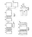
- Figure 1 is a diagrammatic representation of the novel photon detection system;
- Figure 2 is a diagrammatic representation of the imaging photon detector used in the system of Figure 1;
- Figure 3 is a representation of both background noise signals and signals from discrete areas of reaction (whereby the background noise signals may be cancelled, leaving only reaction signals);
- Figure 4 represents a carrier in which multiple antibody labels may be used simultaneously or in which a standard reaction may be compared with other reactions;
- Figure 5 is a diagrammatic representation of how a wavelength interference filter may be used with the carrier of Figure 4 to pass only a particular light wavelength, thereby allowing only photons of a particular wavelength corresponding to a labelled antibody to pass to the imaging detector;
- Figure 6 is a schematic representation of a circuit in a microprocessor for subtracting background noise from the sample signals to obtain an output signal representing substantially only pure photon emission from a reactant sample; and
- Figure 7 is a diagrammatic representation of the use of invisible ultraviolet radiation as a source of external light.
- The apparatus of the present invention, which will be described in further detail below, may be utilised with any number of different assay techniques as stated earlier, but will be described with particular reference to the use of luminescent immunoassays in the detection of antigen-antibody reactions. More particularly, the invention can be employed to detect the characteristic reactions of labelled monoclonal and polyclonal antibodies with antigens found in samples such as urine, faeces, blood, milk and water and the like.
- Polyclonal antibodies are well-known. Monoclonal antibodies may be prepared by the technique first described by Kohler and Milstein, Eur. J. Immunol. 6, 292 (1975). In order to detect the presence of particular antigens, the monoclonal antibodies may be labelled with a multitude of different labels, such as luminescent or fluorescent compounds. Further, the particular labels utilised in the present invention must be capable of emitting light once the antigen-antibody reaction occurs, and thus the reactions are designated as "light-emitting reactions". The present invention will be described in general with reference to a luminescent-labelled monoclonal antibody, although fluorescent labels may also be used as disclosed hereafter. As used herein, the term "reactants" means the combination of (1) a monoclonal antibody labelled with a luminescent or fluorescent compound, and (2) an antigen.
- Luminescence is the emission of light by an atom or molecule as an electron is transferred to the ground state from a higher energy state. In both chemiluminescent and bioluminescent reactions, the free energy of a chemical reaction provides the energy required to produce an intermediate reaction or product in an electronically excited state. Subsequent decay back to the ground state is accompanied by emission of light. Bioluminescence is the name given to a special form of chemiluminescence found in biological systems such as the firefly, in which a catalytic protein or enzyme, such as luciferase, increases the efficiency of the luminescent reaction. When this luciferase enzyme is combined with its substrate, luciferin, in the presence of ATP (adenosine triphosphate), magnesium and oxygen, a flash of light is produced, whose intensity is proportional to the amount of ATP present in the sample. The firefly luciferase/luciferin/ATP system is as follows:

- Assays of the invention can directly determine the number of live organisms in a sample, either because the presence of ATP in a test sample indicated live cells, or because of the presence of immunoglobulins labelled with a luminescence-detectable enzyme (like peroxidase or luciferase) .
- Chemiluminescent substances such as luminol may also be utilised in a horseradish peroxidase-catalysed oxidation, as follows:

- In the present invention, the "light-emitting reactions" generate photons which are coupled to an imaging device such as an imaging photon detector, a charge-coupled device, or a vidicon tube (any of a variety of camera tubes having a photoconductive target). In the preferred embodiment, an imaging photon detector is used.
- In particular, the reactions may be generated by reactants spatially arranged in individual areas on a sample carrier in a single row or column or by a two-dimensional array of reactants spatially arranged, for instance, in rows and columns. For example, a carrier may have an array, such as rows, of 1 mm outside diameter nylon tubes containing the labelled monoclonal antibodies, to which is added the specimen or specimens being tested for the presence of an antigen. The fluids involved are self-contained and of a very small volume. Thus, an advantage of the present invention is that the imaging photon detector can quantify (in 10 seconds or less) light emitted from multiple "light-emitting reactions", in volumes of 3 >1 or less, i.e. much smaller than can be used in known apparatus.
- Another carrier suitable for use with an imaging photon detector is a microtiter plate with multiple samples in rows and columns. A particular plate may contain as many as 96 individual wells. Each well contains different labelled monoclonal antibodies adsorbed on the surface of the plate. A portion of the specimen is added to each well. The presence and quantity of a particular antigen in an individual well is determined by the number of photons generated by the antigen-antibody reaction.
- A third carrier involves the principle of using immobilised antibodies on a plurality of filaments; labelled monoclonal antibodies are immobilised in individual areas on a plurality of filaments. Each filament may bear a different labelled monoclonal antibody capable of emitting light upon the detection of an antigen. Because the reactions on the individual filaments generate light, the imaging photon detection system can quantitatively determine the presence of particular antigens.
- The present invention envisages the use of any number of different types of multiple, chemically- produced, light-emitting reactions which can be imaged by the image photon detector. As the samples emit light, the present invention counts the individual photons impinging upon a light sensitive photocathode of an imaging photon detector.
- Each of the above means for containing a plurality of reactants can be used in the apparatus system described below, in which the container is identified as the specimen carrier means.
- The apparatus system will be described with reference to Figures 1 and 2.
- Fig. 1 is a system for quantitative assay analysis of multiple biochemical images using an imaging photon detector. The system enables the detection of very low concentrations of substances present in fluid samples or specimens which, in the course of their reaction, emit light photons under certain conditions. In particular, the system has demonstrated sensitivity in the order of 10-16 and lower.
- Fig. 1 shows a specimen carrier means 10 which may include a plurality of fluid samples all capable of simultaneously undergoing a reaction. Samples can be spaced in individual areas as a row or column or in a two-dimensional array of rows and columns as shown in Fig. 3 and Fig. 4, for example only. The reactions that produce light generate
photons 12 which are focused by anoptical system 14 to form the image of the light outputs of each of the samples on a photoconductive target forming a portion of an imaging photon detector (IPD) 16. Theimaging photon detector 16 will be disclosed in detail hereinafter but is known in the art; it immediately converts incoming light into quantitative information which can be stored and processed within a memory of any conventional computing means such as amicroprocessor 24. - The
imaging detector 16 of the present invention takes simultaneous readings of discrete sample areas such as the solid dark areas of Fig. 3, rather than averaging the readings of the entire sample area (including the carrier area surrounding the sample). Background noise, represented by the shading lines in Fig. 3, is caused by non-specific binding antigens or antibodies to the solid surface of the carrier, which are not washed away in the preparation of the carrier. Conventional detectors read these signals generated by this undesirable binding and, because these conventional detectors average the signal over the entire sample area, they interpret these undesired false signals as a positive reaction. Background noise effectively decreases the sensitivity of the assay at relatively low levels of concentration, where the positive reaction signal has nearly the same intensity level as the background noise. - The present invention eliminates the background noise problem by simultaneously reading the signal from the background environment and the signal from the concentrated reaction area and comparing the two readings. Because the present imaging immunoassay detection system can read signals from numerous discrete reaction areas at the same instant, a real time measurement of the signals from the discrete areas of reaction in a two-dimensional array can be taken, averaged, and compared with the signal representing the background noise caused by the non-specific binding. The
computer 24 can analyse and display the results by subtracting from the signals representing the discrete areas of reactions the signals representing the background noise, as shown in Fig. 6, thereby leaving the pure reaction signals. - Further, since the present system can simultaneously evaluate a carrier, such as a 96-well microtiter tray, without repositioning the carrier or tray as in systems using sequential detection, resolution errors that occur from imprecise mechanical repositioning of the samples between measurements as required in the prior art are eliminated.
- Since the present imaging immunoassay detection system can look at more than one discrete reaction at a time, contrasting reactions can be analysed relative to one another. By way of illustration, in a two-dimensional array of samples as in a microtiter tray represented in Fig. 4, reactions can be compared side-by-side simultaneously. The amount of photons generated by each reaction can be read and analysed by
computer 24 and the relative extent of reaction compared. In this way, a more accurate comparison can be made between specific samples, thus providing better test results. As an example, a negative reaction may be placed in a discrete area A in Fig. 4, to serve as a control for purposes of comparison with_a positive reaction in a discrete area B. The negative reaction in discrete area A may still generate spurious signals caused by non-specific binding, as pointed out earlier. This background noise level is potentially constant across a given carrier such as a microtiter tray and is useful in setting up a base level of signal generation from which more positive reaction can be compared. - Thus, the present imaging system is capable of rapid quantitative analysis of samples. Because of its unique ability to simultaneously read and analyse numerous samples, the time necessary to produce results is dramatically reduced.
- Furthermore, the sensitivity of the present imaging system allows for very accurate measurements even at very low concentrations of the samples. For instance, an imaging photon detector is capable of measuring individual photons of light. By using amplifiers, the system is able to register very low concentrations of materials and is therefore useful in areas such as diagnosing for the presence of infectious organisms, as well as drug monitoring and disease detection.
- Because of its sensitivity, the imaging system can not only detect minute quantities of a reaction samples, but can also read a very small area of reaction. Thus, the amount of reagent and the area which are needed to conduct the assay are less then before, thereby minimising the cost of reagents and carrier materials.
- The output of the
imaging photon detector 16 online 18 comprises analog signals which represents the x-y spatial correspondence of each detected photon, thus identifying electrically the x-y address of the sample or specimen that produced the light. These analog signals are coupled to an analog-to-digital (A/D)converter 20 which produces digital output signals onlines 22 representing the spatial orientation of the specimen source producing the photon received by theimaging photon detector 16 and thus identifying the particular sample or specimen which produces the photon. Thedigital signals 22 are coupled to amicroprocessor 24 which stores and analyses the image information and can be programmed to display it in any desired format. The reactions continue to generate light throughout any desired predetermined period of time, e.g. as little as 10 seconds or less, and the number of photons produced by each reacting sample is accumulated in the memory ofmicroprocessor 24. Thus,microprocessor 24 produces signals online 26 tovideo display 28 andprinter 30 for visual display and analysis of the light received, and accumulated, fromsamples 10. - A bar chart may be displayed on
video terminal 28 which identifies each of the samples and illustrates the relative amount of light or number of photons being generated by each sample. Such a bar chart could also be produced, for a permanent record, byprinter 30. - Also, a two-dimensional image of the array of samples as they are physically located (i.e. their x-y address) can be produced, the intensity of the light generated by each sample being indicated either in colour or by numerals, thus identifying which sample is generating the greatest amount of light. Obviously, the
microprocessor 24 can perform any operation on the samples as desired to correct and calibrate the image and to compensate for any inherent noise in the system such as by subtracting the background noise, as explained earlier. Noise also may be reduced by cooling theimaging photon detector 16 with acooling unit 15 in any well known manner such as by circulating a cooling liquid or a refrigerant about theimaging photon detector 16. Cooling thedetector 16 reduces the tendency for free electrons to be emitted from elements of thedetector 16, and which assist in generating the background noise. - Fig. 2 is a diagrammatic representation of the construction details of the imaging photon detector used in the preferred embodiment herein and which is known in the art. The detector may be type IPDG1 or type PIDF1 manufactured by Instrument Technology Limited in East Sussex, England. The
imaging photon detector 16 is a two-dimensional imaging sensor capable of detecting extremely weak radiation, e.g. capable of detecting an ATP content in the sample down to as low as 10" moles/sample. As indicated earlier, that image is produced in analog form which is converted through an analog-to-digital converter 20 to a digital form for use by themicroprocessor 24. - Light is composed of individual photons. Each individual photon has an extremely small amount of energy associated therewith. In most common images, the light contains fluxes of millions or billions of photons per square centimeter and per second. Using the
imaging photon detector 16, each incoming photon has a high probability of detection by thephotocathode 32. - The
photoconductive target 32 can thus be thought of as equivalent to a photographic film except that it has a sensitivity of the order of 100 times greater. When a photon strikes the lightsensitive photocathode 32, a photoelectron is released fromphotocathode 32 and is immediately accelerated into a series of microchannel plate intensifiers oramplifiers 34. As a result of the intensification created bymicrochannel plates 34, a gain in the range of 3x10⁶ to 3x10⁷ electrons is emitted from the rear of each microchannel plate for each incident photoelectron and thus corresponds to each initially detected photon. The combination of themicrochannel plates 34 thus enables extremely small amounts of light to be detected. - A
resistive anode encoder 36 located immediately behind themicrochannel plates 34 translates the electron burst into signals which can be processed easily into a two-dimensional x-y address of the detected photon and thus the sample. Thus, the analog readout of theresistive anode 36 online 18 in Fig. 1 is used to present a linear x-y registration of each photoelectron event. The read-out through fourorthogonal electrodes 38 is suitably processed to provide digital representation of the x-y position of the incident photoelectron (and thus the sample) by analog-to-digital converter 20 andmicroprocessor 24, both shown in Fig. 1. Thus, by the use of theimaging photodetector 16, the full image of all of thesamples 10 in two dimensions is created by integrating the image focused onto thephotocathode 32, photo-by-photon. Thus, the present system detects and presents information relating to multiple imaging, presents the information immediately upon the occurrence of the emitted light, detects extremely small amounts of light down to and including a single photon, and quantifies such information for each specific x-y sample or specimen address. - Instead of an imaging photon detector (which is preferred), the system may use a charge-coupled device (CCD) as the
imaging device 16. CCD's are well known in the art. They are used in conjunction with an optical lensing system (such asoptical system 14 in Fig. 1) which focuses light from the object being investigated (sample array 10 in Fig. 1) on to the CCD. Varying amounts of light from individual samples are incident on individual pixels within the CCD and charge the pixels to different levels proportional to the incident light. Thus the optical information or light fromsample array 10 is available in analog form across the pixels ofCCD array 16. The analog information is then shifted out of the CCD and converted to digital form in a well known manner by the analog-to-digital converter 20 and is then coupled to a memory incomputer 24 where the various measurement levels and comparisons can be made by appropriate manipulation of the digital information. See "Imaging", The Optical Industry and System Purchasing Directory, 1983, pp. E-72 to E-74. - As is well known in the prior art, the individual pixels within a CCD array are closely spaced and arranged horizontally in rows and vertically in columns so that a given
CCD imaging device 16 provides a fixed number of pixels of information. For instance, some CCD's have 320 vertical columns of pixels and 512 horizontal rows of pixels. - CCD's have several characteristics which make them advantageous in the present invention as an imaging device. CCD's are small and rugged and nave closely spaced pixels and are therefore useful where, as here, precise measurements are required. They also receive an image by the direct reception of light energy without being scanned, and store the received data until the data are transferred to another storage device. Further, the data received from the CCD can be processed by simple comparison or detection techniques, thereby avoiding complex and major time-consuming sampling techniques ordinarily used to process such data.
- Another imaging device which can be used instead of an imaging photon detector or a CCD is a vidicon tube. The name vidicon is generally applied to any of a variety of tubes having a photoconductive target. The vidicon operates in a well known manner and utilises an electron beam to scan a light-sensitive photoconductive target. A transparent conductive layer applied to the front side of the photoconductor serves as the signal or target electrode. The target electrode is operated at a positive voltage with respect to the back side of the photoconductor which operates at cathode (near zero) voltage. In operation, the scanning beam initially charges the back side of the target electrode to cathode potential. When a light pattern (lignt pnoton) is focused on the photoconductor, its conductivity increases in the illuminated areas and the back side of the target charges to more positive values. The electron beam then reads the signal by depositing electrons on the positively charged areas, thereby providing a capacitively coupled signal at the signal output electrode. See "Imaging Devices", RCA Solid State Devices, 19, pp 3-9.
- Tnus, as used in Fig. 1, a
vidicon 16 receives the photons or light output from the respective reactions throughoptics 14 and produces the analog output online 18 as described earlier. The analog output online 18 is coupled to the analog-to-digital converter 20 from which digital signals are processed in the same manner as for the imaging photon detector. - It is also possible to use multiple antibody labels with the imaging immunoassay detection system of the present invention. Different antibodies are labelled with different indicators and correspond to different discrete areas on the carrier medium. Thus, with regard to Fig. 4, discrete area A may have an antibody labelled with an indicator such as luciferase, discrete area B may nave an antibody labelled with an indicator such as a bacterial reductase, and so forth. Since each indicator generates a different wavelength of lignt, each discrete area for each antibody has its own particular wavelength of light which can be detected by imaging
device 16. As can be seen in Fig. 5, awavelengtn interference filter 40 of the desired characteristics is placed betweensamples 10 andoptics 14 such that only photons of a particular wavelength corresponding to an antibody labelled with a particular indicator pass through to theimaging detector 16. In this manner, the novel imaging immunoassay detection system can be made wavelength selective, thereby permitting greater flexibility and sensitivity. - It will be understood, of course, that if a fluorescing material, such as fluorescein, is used as the label, invisible ultraviolet light or black light will have to be used. Fig. 7 illustrates such apparatus, wherein an
ultraviolet light source 54 is powered by anappropriate power source 56. Ultraviolet light rays 58 impinge on samples incarrier 10 which fluoresce if a reaction takes place. The remainder of the circuit operates as described above in connection with Fig. 1. - As shown in Fig. 6, the signals detected by imaging
device 16, representing background noise and sample signals combined, are stored in amemory 42 ofmicroprocessor 24. The detected signals representing background noise alone are stored in amemory 44 ofmicroprocessor 16. By coupling these two stored signals onlines arithmetic unit 50, and subtracting one from the other an output signal is obtained on aline 52, which represents substantially only pure photon emission from any selected reactant sample. Thus, background noise is substantially eliminated or minimised. - The system of the present invention can be used in conjunction with labelled DNA or RNA probes instead of antibodies as a diagnostic tool. DNA probes or RNA probes are specific sequences of amino-acids that are complementary to particular sequences of a sample piece of DNA or RNA. These probe pieces of DNA or RNA can be labelled with an indicator so as to generate a signal, analogous to an immunoassay, and would be contained in a
carrier 10 such as shown in Fig. 1. In use, the DNA or RNA is first removed from a cell or other structure in a sample containing a DNA or RNA sequence. The DNA or RNA is bound to a surface such as nitrocellulose, and is then denatured so that its complementary strands are separated. The DNA or RNA probe, labelled with an indicator, is then added to the sample and, if the specific complementary sequence of the probe is present in the sample, the sample and probe will combine. The unbound label is washed away and the sample containing bound labelled probe is read in the manner described hereinabove with reference to Fig. 1. - Isotope-labelled assays are also within the scope of the present invention. In such an assay, the indicator component is labelled with an isotope, such as
phosphorus -32 or iodine-125, which emits gamma radiation. In the performance of a radioisotopic assay, the isotope-labelled component, typically an antibody, is bound to the analyte of interest, the unbound label is washed away from the reaction zone, and the zone is read. The reading of the central reaction zone is accomplished in this embodiment by the incorporation of a phosphor screen. Phosphor screens are well known in the art and are used to convert electron energy into radiant energy. These screens are composed of a thin layer of luminescent crystals, phosphors, which emit light when bombarded by electrons. In the present case, the phosphor screen receives gamma radiation from the labelled analyte and, in turn, emits photons which are received by the detection system. Thus, in Fig. 1,carrier 10 would be the phosphor screen which received electrons from any reaction and emits light 12 which is focused byoptics 14 and processed in the manner explained previously. In this manner, gamma particles are converted into detectable photons which are received and processed as described hereinabove. Other types of gamma-to-photon conversion means are also usable and within the scope of the present invention. - As an illustration of the sensitivity of the IPD array detector system, the well established firefly luciferase/luciferin-based assay for ATP provides a useful reference. Thus, using the standard "Lumac" firefly luciferase/luciferin reagents for the bioluminescent ATP assay in the Lumac Biocounter luminometer, the lower limit for the assay (carried out as recommended by the manufacturer) is set by the "background" count of photons (of about 10/second) typically experienced. This sets the lower limit of the determination at about 5x10-15 moles ATP per sample. In contrast, using the IPD system described above, the lower limit of the determination, using similar criteria, is set at about 5x10-17 moles ATP.
- The invention will be further illustrated in conjunction with the following Example, which is set forth for purposes of illustration only and not by way of limitation.
- Monoclonal antibodies are prepared according to the method of Kohler and Milstein noted above. In particular, an antibody to Shigella is prepared by the procedure described in WO-A-86/00035 and labelled with luminescent compounds such as the firefly luciferase/luciferin/ATP system. These luminescent labelled antibodies are then adsorbed onto the surface of a microtiter tray. Additionally, each well of the tray may contain labelled monoclonal antibodies to different antigens, thus allowing diagnosis for the presence of a wide variety of different antigens at the same time. This microtiter tray thus contains a number of known antibodies at known x-y addresses or areas on the tray. The tray is then washed with the specimen containing the unknown antigen(s) and an antigen-antibody reaction occurs. Next, the tray is rinsed and unbound antibodies are removed. Then, the tray is placed in the specimen carrier holder of the imaging photon detecting system described above. The presence and amount of the unknown antigen(s) in the specimen are determined by the photons generated by the characteristic antigen-antibody reactions and their x-y location on the microtiter tray.
Claims (17)
Applications Claiming Priority (8)
| Application Number | Priority Date | Filing Date | Title |
|---|---|---|---|
| GB858505822A GB8505822D0 (en) | 1985-03-06 | 1985-03-06 | Array systems |
| GB8505822 | 1985-03-06 | ||
| GB858506865A GB8506865D0 (en) | 1985-03-16 | 1985-03-16 | Assay techniques |
| GB8506865 | 1985-03-16 | ||
| GB8512041 | 1985-05-13 | ||
| GB858512041A GB8512041D0 (en) | 1985-05-13 | 1985-05-13 | Immunoassay |
| GB858517042A GB8517042D0 (en) | 1985-07-05 | 1985-07-05 | Imaging immunoassay detection system |
| GB8517042 | 1985-07-05 |
Publications (2)
| Publication Number | Publication Date |
|---|---|
| EP0194132A2 true EP0194132A2 (en) | 1986-09-10 |
| EP0194132A3 EP0194132A3 (en) | 1988-08-03 |
Family
ID=27449641
Family Applications (1)
| Application Number | Title | Priority Date | Filing Date |
|---|---|---|---|
| EP86301523A Withdrawn EP0194132A3 (en) | 1985-03-06 | 1986-03-04 | Imaging immunoassay detection system and method |
Country Status (1)
| Country | Link |
|---|---|
| EP (1) | EP0194132A3 (en) |
Cited By (27)
| Publication number | Priority date | Publication date | Assignee | Title |
|---|---|---|---|---|
| WO1988004045A1 (en) * | 1986-11-26 | 1988-06-02 | John Rushbrooke | High sensitivity optical imaging apparatus |
| US4948975A (en) * | 1988-09-08 | 1990-08-14 | The United States Of America As Represented By The Secretary Of The Air Force | Quantitative luminescence imaging system |
| WO1990009576A1 (en) * | 1989-02-08 | 1990-08-23 | Plessey Overseas Limited | A method for detecting optical phase changes during biosensor operation, biosensing apparatus and a biosensor adapted for use in the same |
| WO1991009300A1 (en) * | 1989-12-08 | 1991-06-27 | Image Research Limited | Improvements in and relating to light transfer systems and improved cell investigation techniques arising therefrom |
| WO1992003734A1 (en) * | 1990-08-20 | 1992-03-05 | Alain De Weck | A method for measuring t-lymphocyte responses by chemiluminescent assays |
| WO1994000752A1 (en) * | 1992-06-26 | 1994-01-06 | Siemens Aktiengesellschaft | Image processing arrangement |
| FR2693740A1 (en) * | 1992-07-17 | 1994-01-21 | Univ Joseph Fourier | Chemiluminescent tissue or cell analysis - using peroxidase labelling, with signal detection by photon microscope and camera for high sensitivity |
| AU653283B2 (en) * | 1988-07-07 | 1994-09-22 | City Of Hope | Specimen containing block for use in the preparation of multi-specimen slides for immunohistologic procedures |
| WO1994025855A1 (en) * | 1993-04-23 | 1994-11-10 | Potter Colin G | Method of measuring chemiluminescence of multiple samples on a continuous matrix |
| EP0646784A1 (en) * | 1993-09-07 | 1995-04-05 | Bayer Corporation | Video test strip reader and method for evaluating test strips |
| EP0647858A1 (en) * | 1993-10-11 | 1995-04-12 | Wallac Oy | Method and device for counting scintillation light pulses |
| EP0713089A2 (en) * | 1994-11-15 | 1996-05-22 | Biosensor Laboratories Co., Ltd. | Two-dimensional solid phase assay |
| US5700637A (en) * | 1988-05-03 | 1997-12-23 | Isis Innovation Limited | Apparatus and method for analyzing polynucleotide sequences and method of generating oligonucleotide arrays |
| US5702887A (en) * | 1993-03-19 | 1997-12-30 | Chiron Diagnostics Corporation | Long emission wavelength chemiluminescent compounds and their use in test assays |
| US5834758A (en) * | 1994-09-02 | 1998-11-10 | Affymetrix, Inc. | Method and apparatus for imaging a sample on a device |
| WO1998057151A1 (en) * | 1997-06-13 | 1998-12-17 | Fraunhofer-Gesellschaft zur Förderung der angewandten Forschung e.V. | Device for detecting biochemical or chemical substances by fluorescence excitation and method for its production |
| WO1999004247A1 (en) * | 1997-07-14 | 1999-01-28 | Symyx Technologies | Systems and methods for employing optical probes to characterize material properties |
| US5981956A (en) * | 1996-05-16 | 1999-11-09 | Affymetrix, Inc. | Systems and methods for detection of labeled materials |
| WO1999066313A1 (en) * | 1998-06-18 | 1999-12-23 | Pyrosequencing Ab | Reaction monitoring systems |
| US6054270A (en) * | 1988-05-03 | 2000-04-25 | Oxford Gene Technology Limited | Analying polynucleotide sequences |
| EP1046421A2 (en) * | 1990-12-06 | 2000-10-25 | Affymetrix, Inc. | Methods and reagents for very large scale immobilized polymer synthesis |
| US6249593B1 (en) | 1993-02-26 | 2001-06-19 | Ey Laboratories, Inc. | Optical specimen analysis system and method |
| US6491871B1 (en) * | 1989-06-07 | 2002-12-10 | Affymetrix, Inc. | System for determining receptor-ligand binding affinity |
| WO2009063185A1 (en) * | 2007-11-14 | 2009-05-22 | Surescreen Diagnostics Limited | Test results reading method and apparatus |
| US7625697B2 (en) | 1994-06-17 | 2009-12-01 | The Board Of Trustees Of The Leland Stanford Junior University | Methods for constructing subarrays and subarrays made thereby |
| US7811751B2 (en) | 1988-05-03 | 2010-10-12 | Oxford Gene Technology Limited | Analysing polynucleotide sequences |
| US7888494B2 (en) | 1988-05-03 | 2011-02-15 | Oxford Gene Therapy Limited | Analysing polynucleotide sequences |
Citations (4)
| Publication number | Priority date | Publication date | Assignee | Title |
|---|---|---|---|---|
| EP0025350A2 (en) * | 1979-09-05 | 1981-03-18 | Dynatech Ag | Apparatus for detecting luminescent reactions |
| US4320970A (en) * | 1975-11-24 | 1982-03-23 | Dowben Robert M | Photon counting fluorimeter |
| EP0110610A2 (en) * | 1982-11-20 | 1984-06-13 | The University Of Birmingham | Dispensing device and recording apparatus |
| EP0148736A1 (en) * | 1983-12-19 | 1985-07-17 | Wallac Oy | Method and apparatus for luminescence measurement |
-
1986
- 1986-03-04 EP EP86301523A patent/EP0194132A3/en not_active Withdrawn
Patent Citations (4)
| Publication number | Priority date | Publication date | Assignee | Title |
|---|---|---|---|---|
| US4320970A (en) * | 1975-11-24 | 1982-03-23 | Dowben Robert M | Photon counting fluorimeter |
| EP0025350A2 (en) * | 1979-09-05 | 1981-03-18 | Dynatech Ag | Apparatus for detecting luminescent reactions |
| EP0110610A2 (en) * | 1982-11-20 | 1984-06-13 | The University Of Birmingham | Dispensing device and recording apparatus |
| EP0148736A1 (en) * | 1983-12-19 | 1985-07-17 | Wallac Oy | Method and apparatus for luminescence measurement |
Cited By (38)
| Publication number | Priority date | Publication date | Assignee | Title |
|---|---|---|---|---|
| WO1988004045A1 (en) * | 1986-11-26 | 1988-06-02 | John Rushbrooke | High sensitivity optical imaging apparatus |
| AU592913B2 (en) * | 1986-11-26 | 1990-01-25 | Richard Ansorge | High sensitivity optical imaging apparatus |
| US7888494B2 (en) | 1988-05-03 | 2011-02-15 | Oxford Gene Therapy Limited | Analysing polynucleotide sequences |
| US7811751B2 (en) | 1988-05-03 | 2010-10-12 | Oxford Gene Technology Limited | Analysing polynucleotide sequences |
| US6054270A (en) * | 1988-05-03 | 2000-04-25 | Oxford Gene Technology Limited | Analying polynucleotide sequences |
| US5700637A (en) * | 1988-05-03 | 1997-12-23 | Isis Innovation Limited | Apparatus and method for analyzing polynucleotide sequences and method of generating oligonucleotide arrays |
| AU653283B2 (en) * | 1988-07-07 | 1994-09-22 | City Of Hope | Specimen containing block for use in the preparation of multi-specimen slides for immunohistologic procedures |
| US4948975A (en) * | 1988-09-08 | 1990-08-14 | The United States Of America As Represented By The Secretary Of The Air Force | Quantitative luminescence imaging system |
| WO1990009576A1 (en) * | 1989-02-08 | 1990-08-23 | Plessey Overseas Limited | A method for detecting optical phase changes during biosensor operation, biosensing apparatus and a biosensor adapted for use in the same |
| US6491871B1 (en) * | 1989-06-07 | 2002-12-10 | Affymetrix, Inc. | System for determining receptor-ligand binding affinity |
| AU651801B2 (en) * | 1989-12-08 | 1994-08-04 | Cambridge Imaging Limited | Improvements in and relating to light transfer systems and improved cell investigation techniques arising therefrom |
| WO1991009300A1 (en) * | 1989-12-08 | 1991-06-27 | Image Research Limited | Improvements in and relating to light transfer systems and improved cell investigation techniques arising therefrom |
| WO1992003734A1 (en) * | 1990-08-20 | 1992-03-05 | Alain De Weck | A method for measuring t-lymphocyte responses by chemiluminescent assays |
| EP1046421A2 (en) * | 1990-12-06 | 2000-10-25 | Affymetrix, Inc. | Methods and reagents for very large scale immobilized polymer synthesis |
| EP1046421A3 (en) * | 1990-12-06 | 2001-09-19 | Affymetrix, Inc. | Methods and reagents for very large scale immobilized polymer synthesis |
| WO1994000752A1 (en) * | 1992-06-26 | 1994-01-06 | Siemens Aktiengesellschaft | Image processing arrangement |
| FR2693740A1 (en) * | 1992-07-17 | 1994-01-21 | Univ Joseph Fourier | Chemiluminescent tissue or cell analysis - using peroxidase labelling, with signal detection by photon microscope and camera for high sensitivity |
| US6249593B1 (en) | 1993-02-26 | 2001-06-19 | Ey Laboratories, Inc. | Optical specimen analysis system and method |
| US5702887A (en) * | 1993-03-19 | 1997-12-30 | Chiron Diagnostics Corporation | Long emission wavelength chemiluminescent compounds and their use in test assays |
| US5879894A (en) * | 1993-03-19 | 1999-03-09 | Chiron Diagnostics Corporation | Long emission wavelength chemiluminescent compounds and their use in test assays |
| WO1994025855A1 (en) * | 1993-04-23 | 1994-11-10 | Potter Colin G | Method of measuring chemiluminescence of multiple samples on a continuous matrix |
| EP0646784A1 (en) * | 1993-09-07 | 1995-04-05 | Bayer Corporation | Video test strip reader and method for evaluating test strips |
| EP0647858A1 (en) * | 1993-10-11 | 1995-04-12 | Wallac Oy | Method and device for counting scintillation light pulses |
| US7625697B2 (en) | 1994-06-17 | 2009-12-01 | The Board Of Trustees Of The Leland Stanford Junior University | Methods for constructing subarrays and subarrays made thereby |
| US5834758A (en) * | 1994-09-02 | 1998-11-10 | Affymetrix, Inc. | Method and apparatus for imaging a sample on a device |
| US6252236B1 (en) | 1994-09-02 | 2001-06-26 | Affymetrix Technologies, N.V. | Method and apparatus for imaging a sample on a device |
| US6025601A (en) * | 1994-09-02 | 2000-02-15 | Affymetrix, Inc. | Method and apparatus for imaging a sample on a device |
| EP0713089A3 (en) * | 1994-11-15 | 1997-07-30 | Bio Sensor Kenkyusho Kk | Two-dimensional solid phase assay |
| US5981202A (en) * | 1994-11-15 | 1999-11-09 | Biosensor Laboratories Co., Ltd. | Two-dimensional solid phase assay |
| EP0713089A2 (en) * | 1994-11-15 | 1996-05-22 | Biosensor Laboratories Co., Ltd. | Two-dimensional solid phase assay |
| US6207960B1 (en) | 1996-05-16 | 2001-03-27 | Affymetrix, Inc | System and methods for detection of labeled materials |
| US6597000B2 (en) | 1996-05-16 | 2003-07-22 | Affymetrix, Inc. | Systems and methods for detection of labeled materials |
| US5981956A (en) * | 1996-05-16 | 1999-11-09 | Affymetrix, Inc. | Systems and methods for detection of labeled materials |
| US6534011B1 (en) | 1997-06-13 | 2003-03-18 | Fraunhofer-Gesellschaft Zur Forderung Der Angewandten Forschung E.V. | Device for detecting biochemical or chemical substances by fluorescence excitation |
| WO1998057151A1 (en) * | 1997-06-13 | 1998-12-17 | Fraunhofer-Gesellschaft zur Förderung der angewandten Forschung e.V. | Device for detecting biochemical or chemical substances by fluorescence excitation and method for its production |
| WO1999004247A1 (en) * | 1997-07-14 | 1999-01-28 | Symyx Technologies | Systems and methods for employing optical probes to characterize material properties |
| WO1999066313A1 (en) * | 1998-06-18 | 1999-12-23 | Pyrosequencing Ab | Reaction monitoring systems |
| WO2009063185A1 (en) * | 2007-11-14 | 2009-05-22 | Surescreen Diagnostics Limited | Test results reading method and apparatus |
Also Published As
| Publication number | Publication date |
|---|---|
| EP0194132A3 (en) | 1988-08-03 |
Similar Documents
| Publication | Publication Date | Title |
|---|---|---|
| US5096807A (en) | Imaging immunoassay detection system with background compensation and its use | |
| EP0194132A2 (en) | Imaging immunoassay detection system and method | |
| US4922092A (en) | High sensitivity optical imaging apparatus | |
| CN100465619C (en) | Assay plates, reader systems and methods for luminescence test measurements | |
| US6263095B1 (en) | Imaging method and apparatus | |
| JP3448090B2 (en) | Energy transfer detection method and apparatus | |
| US4626684A (en) | Rapid and automatic fluorescence immunoassay analyzer for multiple micro-samples | |
| JP5551211B2 (en) | Luminescence detection workstation | |
| JP3418402B2 (en) | Improved imaging method and apparatus | |
| US20030157581A1 (en) | Use of an imaging photoelectric flat sensor for evaluating biochips and imaging method therefor | |
| US5945344A (en) | Electrochemiluminescence method | |
| EP0327588B1 (en) | High sensitivity optical imaging apparatus | |
| US7081365B2 (en) | Scintillation proximity test | |
| US7585624B2 (en) | Detection of the energy of photons from biological assays | |
| EP0937238B1 (en) | Method for assay analysis | |
| Berthold et al. | Luminometer design and low light detection | |
| JPS61217745A (en) | Image immunity test detector and method | |
| Jessop | Imaging proximity assays | |
| CN213506966U (en) | Gene chip hybridization result detector based on fluorescence lifetime imaging | |
| EP1331484B1 (en) | Chemiluminescence method for producing biochemical analysis data and apparatus used therefor | |
| JP2024506285A (en) | Sensitive chemiluminescence detection system and method | |
| Hooper | Ultra-sensitive quantitative imaging of luminescent immunoassays and cellular assays using image intensifier and CCD detectors | |
| FI96067C (en) | Method and apparatus for counting scintillation light pulses | |
| AU2004201406B2 (en) | A digital imaging system for assays in well plates, gels and blots | |
| JP2728796B2 (en) | Chemiluminescence measuring method and measuring device |
Legal Events
| Date | Code | Title | Description |
|---|---|---|---|
| PUAI | Public reference made under article 153(3) epc to a published international application that has entered the european phase |
Free format text: ORIGINAL CODE: 0009012 |
|
| AK | Designated contracting states |
Kind code of ref document: A2 Designated state(s): DE GB |
|
| RAP1 | Party data changed (applicant data changed or rights of an application transferred) |
Owner name: MUREX CORPORATION |
|
| PUAL | Search report despatched |
Free format text: ORIGINAL CODE: 0009013 |
|
| AK | Designated contracting states |
Kind code of ref document: A3 Designated state(s): DE GB |
|
| 17P | Request for examination filed |
Effective date: 19890202 |
|
| 17Q | First examination report despatched |
Effective date: 19900516 |
|
| STAA | Information on the status of an ep patent application or granted ep patent |
Free format text: STATUS: THE APPLICATION IS DEEMED TO BE WITHDRAWN |
|
| 18D | Application deemed to be withdrawn |
Effective date: 19900927 |
|
| RIN1 | Information on inventor provided before grant (corrected) |
Inventor name: LEABACK, DAVID HERBERT |