EP0196344A1 - Anti-closure device for flexible containers - Google Patents
Anti-closure device for flexible containers Download PDFInfo
- Publication number
- EP0196344A1 EP0196344A1 EP85103917A EP85103917A EP0196344A1 EP 0196344 A1 EP0196344 A1 EP 0196344A1 EP 85103917 A EP85103917 A EP 85103917A EP 85103917 A EP85103917 A EP 85103917A EP 0196344 A1 EP0196344 A1 EP 0196344A1
- Authority
- EP
- European Patent Office
- Prior art keywords
- bag
- container
- anticlosure
- dispensing
- hygroscopic
- Prior art date
- Legal status (The legal status is an assumption and is not a legal conclusion. Google has not performed a legal analysis and makes no representation as to the accuracy of the status listed.)
- Granted
Links
Images


Classifications
-
- B—PERFORMING OPERATIONS; TRANSPORTING
- B65—CONVEYING; PACKING; STORING; HANDLING THIN OR FILAMENTARY MATERIAL
- B65D—CONTAINERS FOR STORAGE OR TRANSPORT OF ARTICLES OR MATERIALS, e.g. BAGS, BARRELS, BOTTLES, BOXES, CANS, CARTONS, CRATES, DRUMS, JARS, TANKS, HOPPERS, FORWARDING CONTAINERS; ACCESSORIES, CLOSURES, OR FITTINGS THEREFOR; PACKAGING ELEMENTS; PACKAGES
- B65D77/00—Packages formed by enclosing articles or materials in preformed containers, e.g. boxes, cartons, sacks or bags
- B65D77/04—Articles or materials enclosed in two or more containers disposed one within another
- B65D77/06—Liquids or semi-liquids or other materials or articles enclosed in flexible containers disposed within rigid containers
- B65D77/062—Flexible containers disposed within polygonal containers formed by folding a carton blank
- B65D77/065—Spouts, pouring necks or discharging tubes fixed to or integral with the flexible container
- B65D77/067—Spouts, pouring necks or discharging tubes fixed to or integral with the flexible container combined with a valve, a tap or a piercer
-
- B—PERFORMING OPERATIONS; TRANSPORTING
- B65—CONVEYING; PACKING; STORING; HANDLING THIN OR FILAMENTARY MATERIAL
- B65D—CONTAINERS FOR STORAGE OR TRANSPORT OF ARTICLES OR MATERIALS, e.g. BAGS, BARRELS, BOTTLES, BOXES, CANS, CARTONS, CRATES, DRUMS, JARS, TANKS, HOPPERS, FORWARDING CONTAINERS; ACCESSORIES, CLOSURES, OR FITTINGS THEREFOR; PACKAGING ELEMENTS; PACKAGES
- B65D2231/00—Means for facilitating the complete expelling of the contents
- B65D2231/001—Means for facilitating the complete expelling of the contents the container being a bag
- B65D2231/002—Means for facilitating the complete expelling of the contents the container being a bag comprising strips forming channels or liquid passageways
-
- B—PERFORMING OPERATIONS; TRANSPORTING
- B65—CONVEYING; PACKING; STORING; HANDLING THIN OR FILAMENTARY MATERIAL
- B65D—CONTAINERS FOR STORAGE OR TRANSPORT OF ARTICLES OR MATERIALS, e.g. BAGS, BARRELS, BOTTLES, BOXES, CANS, CARTONS, CRATES, DRUMS, JARS, TANKS, HOPPERS, FORWARDING CONTAINERS; ACCESSORIES, CLOSURES, OR FITTINGS THEREFOR; PACKAGING ELEMENTS; PACKAGES
- B65D2231/00—Means for facilitating the complete expelling of the contents
- B65D2231/001—Means for facilitating the complete expelling of the contents the container being a bag
- B65D2231/004—Means for facilitating the complete expelling of the contents the container being a bag comprising rods or tubes provided with radial openings, ribs or the like, e.g. dip-tubes, spiral rods
Definitions
- This invention relates generally to flexible bag containers and in particular to a novel means for preventing accidental sealing of a bag aperture by the opposite surface of the bag.
- Flexible, sealable, laminated plastic container bags are rapidly gaining popularity for packaging of various products that may be deleteriously affected by exposure to the atmosphere or to other contaminating environments.
- Comestibles, and particularly liquids such as wines are often packaged in sealed bags that are housed in rigid boxes for convenient shipping, storing and eventual purchase by the consumer who then pierces the seal and attaches a tap for dispensing of the fluid.
- One important advantage of such a bag-in-box dispensing system is that the bag shrinks in volume as the fluid level is lowered and thus no oxidizing atmsphere is able to reach the contents.
- a four liter capacity flexible bag may entrap a half liter or more of the product in the folds of the collapsing bag; this half liter can only be removed by cutting open the bag.
- dip tube to the fitment or spout that is attached to the aperture.
- the dip tube extends into the flexible bag to prevent the bag from closing on itself, thus providing a path for the entrapped contents to reach the aperture through which they are expelled. It is to be noted that the dip tube is attached to the spout and is not available for the sealed flexible bag without dispensing aperture as discussed above as the first degign.
- the present invention is for a dip tube, or tongue, that is attached during manufacture of the flexible plastic bag to the inner wall and adjacent the position of the dispensing aperture.
- the tongue is attached to the bag inner wall near the point of a bag piercing or dispensing tap.
- the tongue attached to the inner wall is made of laminate of two dissimilar materials, one being hygroscopic, the other non-hygroscopic, so that upon the introduction of moisture into the bag, the dissimilar materials in the tongue will cause the tongue to curl into a tubular pattern.
- This dip tube will further separate the inner walls of the container to prevent their closure and thus permit free flow through the dispensing aperture.
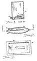
- FIG. 1 is a cross section view illustrating a. typical flexible plastic bag 16 within a ridig box 18 which supports a fitment 20 attached to the dispensing aperture of the bag 16.
- the bag in box container is generally used for the bulk storage and dispensing of a fluid that may be affected by exposure to the atmosphere but the bag 16 may be used for the storage and dispensing of any free-flowing dry material.
- the fitment 20 is used to fill the flexible bag 16 and also to dispense the content therefrom after removal of a seal applied to the fitment 20 after filling.
- the bag 16 When filled, the bag 16 is normally expanded into the entire volume of the rigid box 18 and may contain several gallons of a liquid or dry material. As the contents of the bag 16 is dispensed through an appropriate valve or tap connected to the apertured fitment 20 the bag 16 shrinks without admitting any exterior air that may contaminate the remainder of its contents. However, as the bag collapses its surfaces very often close against the interior surface of the aperture of fitment 20 to seal the remaining fluid in ' che container or captures quantities of the liquid within folds formed in the bag 16 during its collapse, as illustrated in FIG. 1. In such systems, this captured fluid can only be recovered by opening the rigid box 18 and the flexible plastic box 16 therein.
- FIG. 2 is a sectional view illustrating a flexible plastic bag 22-which, during manufacture, is provided with a relatively stiff plastic tongue 24 that is attached to the inner wall of the bag adjacent a bag aperture 26 which will be welded to the box fitment such as the fitment 20 in FIG. 1.
- the flexible bag in FIG. 2 is filled through the aperture 26, sealed and inserted into a rigid box such as the box 18 of FIG. 1.
- the seal is broken and the flexible bag 22 collapses as the fluid is drained therefrom.
- the relatively stiff tongue 24 which extends through at least half of the length of the bag and which is formed with an L-shaped segment 28 adjacent the aperture 26, will both prevent folds from occurring within the bag and prevent the rear surface 30 from closing over the aperture 26. Thus, all fluid will be drained from the bag without the danger of entraping portions in plastic folds or behind a closed aperture.
- FIG. 3 is a sectional view taken along the lines 3-3 of FIG. 2 and illustrates the tongue 24 to be a relatively narrow but long member suitably positioned with respect to the aperture 26 to prevent accidental closure of the bag 22.
- the flexible bag 22 is preferably formed from two sheets of plastic that are welded together around the periphery 32 to form the bag. Prior to the joining of the two sides, the tongue 24 is welded to or otherwise formed on the one bag surface at a position adjacent a filling and dispensing aperture.
- FIG. 4 is a cross sectional illustration of a bag similar to that illustrated in FIG. 2 but without the filling and dispensing aperture.
- Bags such as that illustrated in FIG. 4 are of the type that are opened by a piercing dispenser tap which pierces the surface of the filled and sealed plastic bag to dispense the contents therefrom.
- a small aperture is cut through one surface of the bag, the bag is filled and the aperture is then sealed, usually by heat welding the surface containing the filling aperture against the opposite surface of the bag.
- the bag 4 is provided with an L-shaped tongue 36 the short section of which is attached to one surface of the bag near the point where a piercing dispensing tap would enter the bag. It will be noted from an inspection of FIG. 4 that the elongated tongue 36 will prevent collapse of the bag or sealing of the dispensing tap if the tap pierces either wall of the bag at a point near the attachment of the tongue.
- FIG. 5 is sectional side view of two such interconnected bags 38 and 40 similar to that disclosed in FIG. 2.
- Each bag contains an L-shaped tongue 42 which will prevent the entrapment of portions of the contents of the bag as the bag collapses during the dispensing of the contents.
- the tongue 42 in each of the bags 38, 40 of FIG. 5 may be a semi rigid element as shown and described in connection with FIGs. 2 and 3, or is preferably formed of a laminate of two dissimilar materials as shown in FIGs. 6, 7 and 8.
- FIG. 6 is a plan view illustrating a portion of a laminate of two dissimilar materials and illustrates a plurality of U-shaped cuts 44 which penetrate through both of the layers forming the laminate as will be subsequently explained.
- FIG. 7 is a cross sectional view taken along the line 7-7 of FIG. 6 and illustrates a top laminate 46 of a non-hygroscopic, or low moisture absorption material such as polyethylene attached to and overlying a hygroscopic or high moisture absorption material 48 such as, for example, nylon.
- FIG. 8 is a sectional view of the material of FIG. 7 reacting to the introduction of a moisture to the mateiral and in particularly in the areas of the U-shaped perforations.
- Moisture being absorbed by the hygroscopic layer 48 causes the material in that layer to expand whereas the low moisture absorption material in the layer 46 is unaffected.
- the layers 46 and 48 are laminated together, the portions in the U-shaped sections ' 44 will curl as indicated in FIG. 8. It is true that the entire length of the laminated material will also curl slightly, however the portions entering the material at the U-shaped sections 48 will rapidly curl tc provde a thickened series of individual dip tubes that will further separate the inner surfaces of a flexible plastic bag.
- the dip tube 50 will curl as indicated in the drawing upon a relatively long exposure to moisture within the flexible bag.
- the curl 52 will bend as illustrated upon shorter exposure to moisture and the curl 56 starts to bend as illustrated within a relatively short period after its first exposure to moisture in the flexible bag.
- FIG. 9 illustrates another embodiment of a flat tongue 60 containing a plurality of relatively equally spaced apertures 62 that penetrates both upper layer 64 and bottom layer 66 of the laminated material as best illustrated in the edge view of FIG. 10.
- the bottom layer 66 is preferably formed of a low absorption material whereas the laminated upper layer 64 is a high absorption material.
- the round holes 62 through the laminate do not have the elongated parallel U-shaped cuts 44 of FIG. 6. Therefore, the flat hygroscopic/non hygroscopic laminate of FIGs. 9 and 10 will bend into a tubular configuration when subjected to moisture, as illustrated in FIGs. 11, 12 and 13.
- FIG. 9 illustrates another embodiment of a flat tongue 60 containing a plurality of relatively equally spaced apertures 62 that penetrates both upper layer 64 and bottom layer 66 of the laminated material as best illustrated in the edge view of FIG. 10.
- the bottom layer 66 is preferably formed of a low absorption material whereas the laminated upper layer 64
- FIG. 11 illustrates a tubular shaped dip tube 68 which was formed from the flat laminate 60 to FIG. 9.
- FIG. 12 is a cross sectional view taken along the lines 12-12 of FIG. 11 and illustrates the tube formed by the expansion of the high moisture absorption material 64 laminated to the non-hygroscopic layer 66 which now forms the core of the dip tube.
- FIG. 13 is a perspective view illustrating a dip tube 70 which is identical to the dip tube 68 of FIGs. 11 and 12 but which illustrates the end portion 72 which is heat welded or otherwise connected to the inner surface of a flexible plastic bag such as that illustrated in FIG. 14.
- FIG. 14 is a sectional view of a flexible plastic bag 74 having a filling and dispensing aperture 76.
- the dip tube 70 Attached to the inner surface of the bag 74 and adjacent the edge of the aperture 76 is the dip tube 70 which was a flat planer laminate of two dissimilar materials until moisture within the bag 74 penetrated the aperture through the flat laminate to expand the high absorption layer laminate and thereby form a dip tube 70 for preventing closure of the dispensing-aperture or the entrapment of fluids within the collapsing flexible bag.
Abstract
Description
- This invention relates generally to flexible bag containers and in particular to a novel means for preventing accidental sealing of a bag aperture by the opposite surface of the bag.
- Flexible, sealable, laminated plastic container bags are rapidly gaining popularity for packaging of various products that may be deleteriously affected by exposure to the atmosphere or to other contaminating environments. Comestibles, and particularly liquids such as wines, are often packaged in sealed bags that are housed in rigid boxes for convenient shipping, storing and eventual purchase by the consumer who then pierces the seal and attaches a tap for dispensing of the fluid. One important advantage of such a bag-in-box dispensing system is that the bag shrinks in volume as the fluid level is lowered and thus no oxidizing atmsphere is able to reach the contents.
- One problem encountered with the flexible bag dispensers is that the dispensing aperture in one surface of the bag often becomes covered with the opposite surface, or forms sealed pockets, as the bag shrinks in volume. Thus, for example, a four liter capacity flexible bag may entrap a half liter or more of the product in the folds of the collapsing bag; this half liter can only be removed by cutting open the bag.
- There are two principle designs for flexible laminated plastic bags used in the packaging industry. In one design, the bag is filled through an entrance aperture that is then sealed, usually by heat sealing against the opposite surface of the plastic bag. Thus in this design, there is no dispensing aperture and the contents are eventually dispensed by a piercing tap such as disclosed in U.S. Patent No. 4,322,018 of March 30, 1982. In the second design, the plastic bag is provided with an aperture to which is attached a fitment or spout acceptable to most automatic filling machinery. The bag is thus filled through the aperture which is then sealed until opened by the consumer's dispensing device. Both of the described bag designs are available as a continuous interconnected web of bags for use with the above mentioned automatic filling machinery as described in U.S. Patent 4,386,636 of June 7, 1983.
- To prevent the faces of a flexible bag from sealing off the dispensing aperture and/or for capturing a pocket of the contents, some manufacturers have attached a so- called "dip tube" to the fitment or spout that is attached to the aperture. The dip tube extends into the flexible bag to prevent the bag from closing on itself, thus providing a path for the entrapped contents to reach the aperture through which they are expelled. It is to be noted that the dip tube is attached to the spout and is not available for the sealed flexible bag without dispensing aperture as discussed above as the first degign.
- The present invention is for a dip tube, or tongue, that is attached during manufacture of the flexible plastic bag to the inner wall and adjacent the position of the dispensing aperture. In bags that are fully sealed and without performed dispensing apertures, the tongue is attached to the bag inner wall near the point of a bag piercing or dispensing tap. In the preferred embodiment, the tongue attached to the inner wall is made of laminate of two dissimilar materials, one being hygroscopic, the other non-hygroscopic, so that upon the introduction of moisture into the bag, the dissimilar materials in the tongue will cause the tongue to curl into a tubular pattern. This dip tube will further separate the inner walls of the container to prevent their closure and thus permit free flow through the dispensing aperture.
- In the drawings that illustrate the preferred embodiment of the invention:
- FIG. 1 is a sectional elevation view of a typical prior art plastic bag in a rigid container and illustrates the entrapment of fluid in the folds of a shrinking bag;
- FIG. 2 is a sectional side view of a plastic container bag with an internal tongue attached near the container dispensing aperture;
- FIG. 3 is a sectional view taken along the lines 3 - 3 of FIG. 2;
- FIG. 4 is a sectional view of an internal tongue attached to the inner walls of a sealed, flexible plastic bag without a dispensing aperture;
- FIG. 5 is a sectional view of a section of an interconnected web of bags used with automatic filling machinery and illustrates the attachment of the internal tongues;
- FIG. 6 is a plan view of a laminate of two dissimilar tongues and illustrates U-shaped cuts through the surface;
- FIG. 7 is a sectional view taken along the lines 7 - 7 of FIG. 6;
- FIG. 8 is a sectional view of the tongue of FIG. 7 illustrating typical formation of dip tubes from U-shaped segments in a tongue upon the introduction of moisture;
- FIG. 9 is a plan view illustrating another form of a dissimilar laminate for forming a dip tube;
- FIG. 10 is a sectional side view of the laminate of FIG. 9;
- FIG. 11 illustrates the laminate of FIGs. 9 and 10 formed into a dip tube by the exposure to moisture;
- FIG. 12 is a sectional cross sectional view taken along the lines 12 - 12 of FIG. 11;
- FIG. 13 is a perspective view of the dip tube of FIGs. 11 and 12; and
- FIG. 14 is a perspective sectional view of the dip tube of FIGs. 11 - 13 as a part of a flexible plastic container bag.
- FIG. 1 is a cross section view illustrating a. typical flexible
plastic bag 16 within aridig box 18 which supports afitment 20 attached to the dispensing aperture of thebag 16. The bag in box container is generally used for the bulk storage and dispensing of a fluid that may be affected by exposure to the atmosphere but thebag 16 may be used for the storage and dispensing of any free-flowing dry material. Normally, thefitment 20 is used to fill theflexible bag 16 and also to dispense the content therefrom after removal of a seal applied to thefitment 20 after filling. - When filled, the
bag 16 is normally expanded into the entire volume of therigid box 18 and may contain several gallons of a liquid or dry material. As the contents of thebag 16 is dispensed through an appropriate valve or tap connected to the aperturedfitment 20 thebag 16 shrinks without admitting any exterior air that may contaminate the remainder of its contents. However, as the bag collapses its surfaces very often close against the interior surface of the aperture offitment 20 to seal the remaining fluid in 'che container or captures quantities of the liquid within folds formed in thebag 16 during its collapse, as illustrated in FIG. 1. In such systems, this captured fluid can only be recovered by opening therigid box 18 and the flexibleplastic box 16 therein. - FIG. 2 is a sectional view illustrating a flexible plastic bag 22-which, during manufacture, is provided with a relatively stiff
plastic tongue 24 that is attached to the inner wall of the bag adjacent abag aperture 26 which will be welded to the box fitment such as thefitment 20 in FIG. 1. In use, the flexible bag in FIG. 2 is filled through theaperture 26, sealed and inserted into a rigid box such as thebox 18 of FIG. 1. When the fluid within the bag is eventually dispensed, the seal is broken and theflexible bag 22 collapses as the fluid is drained therefrom. However, the relativelystiff tongue 24 which extends through at least half of the length of the bag and which is formed with an L-shaped segment 28 adjacent theaperture 26, will both prevent folds from occurring within the bag and prevent therear surface 30 from closing over theaperture 26. Thus, all fluid will be drained from the bag without the danger of entraping portions in plastic folds or behind a closed aperture. - FIG. 3 is a sectional view taken along the lines 3-3 of FIG. 2 and illustrates the
tongue 24 to be a relatively narrow but long member suitably positioned with respect to theaperture 26 to prevent accidental closure of thebag 22. It will be noticed from an inspection of FIGURES 2 and 3 that theflexible bag 22 is preferably formed from two sheets of plastic that are welded together around theperiphery 32 to form the bag. Prior to the joining of the two sides, thetongue 24 is welded to or otherwise formed on the one bag surface at a position adjacent a filling and dispensing aperture. - FIG. 4 is a cross sectional illustration of a bag similar to that illustrated in FIG. 2 but without the filling and dispensing aperture. Bags such as that illustrated in FIG. 4 are of the type that are opened by a piercing dispenser tap which pierces the surface of the filled and sealed plastic bag to dispense the contents therefrom. To fill a bag such as that illustrated in FIG. 4, a small aperture is cut through one surface of the bag, the bag is filled and the aperture is then sealed, usually by heat welding the surface containing the filling aperture against the opposite surface of the bag. In FIG. 4, the bag 4 is provided with an L-
shaped tongue 36 the short section of which is attached to one surface of the bag near the point where a piercing dispensing tap would enter the bag. It will be noted from an inspection of FIG. 4 that theelongated tongue 36 will prevent collapse of the bag or sealing of the dispensing tap if the tap pierces either wall of the bag at a point near the attachment of the tongue. - As previously mentioned, flexible plastic bags are used with conventional automatic filling equiment are fed toward the filling station as a web of interconnected bags. FIG. 5 is sectional side view of two such interconnected
bags shaped tongue 42 which will prevent the entrapment of portions of the contents of the bag as the bag collapses during the dispensing of the contents. - The
tongue 42 in each of thebags U-shaped cuts 44 which penetrate through both of the layers forming the laminate as will be subsequently explained. FIG. 7 is a cross sectional view taken along the line 7-7 of FIG. 6 and illustrates atop laminate 46 of a non-hygroscopic, or low moisture absorption material such as polyethylene attached to and overlying a hygroscopic or highmoisture absorption material 48 such as, for example, nylon. - FIG. 8 is a sectional view of the material of FIG. 7 reacting to the introduction of a moisture to the mateiral and in particularly in the areas of the U-shaped perforations. Moisture being absorbed by the
hygroscopic layer 48 causes the material in that layer to expand whereas the low moisture absorption material in thelayer 46 is unaffected. Because thelayers U-shaped sections ' 44 will curl as indicated in FIG. 8. It is true that the entire length of the laminated material will also curl slightly, however the portions entering the material at theU-shaped sections 48 will rapidly curl tc provde a thickened series of individual dip tubes that will further separate the inner surfaces of a flexible plastic bag. In FIG. 8, thedip tube 50 will curl as indicated in the drawing upon a relatively long exposure to moisture within the flexible bag. Thecurl 52 will bend as illustrated upon shorter exposure to moisture and thecurl 56 starts to bend as illustrated within a relatively short period after its first exposure to moisture in the flexible bag. - FIG. 9 illustrates another embodiment of a
flat tongue 60 containing a plurality of relatively equally spacedapertures 62 that penetrates bothupper layer 64 andbottom layer 66 of the laminated material as best illustrated in the edge view of FIG. 10. In the embodiment illustrated, thebottom layer 66 is preferably formed of a low absorption material whereas the laminatedupper layer 64 is a high absorption material. It will be noted that the round holes 62 through the laminate do not have the elongated parallelU-shaped cuts 44 of FIG. 6. Therefore, the flat hygroscopic/non hygroscopic laminate of FIGs. 9 and 10 will bend into a tubular configuration when subjected to moisture, as illustrated in FIGs. 11, 12 and 13. FIG. 11 illustrates a tubular shapeddip tube 68 which was formed from theflat laminate 60 to FIG. 9. FIG. 12 is a cross sectional view taken along the lines 12-12 of FIG. 11 and illustrates the tube formed by the expansion of the highmoisture absorption material 64 laminated to thenon-hygroscopic layer 66 which now forms the core of the dip tube. - FIG. 13 is a perspective view illustrating a
dip tube 70 which is identical to thedip tube 68 of FIGs. 11 and 12 but which illustrates theend portion 72 which is heat welded or otherwise connected to the inner surface of a flexible plastic bag such as that illustrated in FIG. 14. FIG. 14 is a sectional view of a flexibleplastic bag 74 having a filling and dispensingaperture 76. Attached to the inner surface of thebag 74 and adjacent the edge of theaperture 76 is thedip tube 70 which was a flat planer laminate of two dissimilar materials until moisture within thebag 74 penetrated the aperture through the flat laminate to expand the high absorption layer laminate and thereby form adip tube 70 for preventing closure of the dispensing-aperture or the entrapment of fluids within the collapsing flexible bag. - Having thus described our invention what we claim is:
Claims (9)
Priority Applications (2)
| Application Number | Priority Date | Filing Date | Title |
|---|---|---|---|
| DE8585103917T DE3571592D1 (en) | 1985-04-01 | 1985-04-01 | Anti-closure device for flexible containers |
| AT85103917T ATE44704T1 (en) | 1985-04-01 | 1985-04-01 | ANTI-CLOSING DEVICE FOR DEFORMABLE CONTAINERS. |
Applications Claiming Priority (1)
| Application Number | Priority Date | Filing Date | Title |
|---|---|---|---|
| US06/555,045 US4524458A (en) | 1983-11-25 | 1983-11-25 | Moisture responsive stiffening members for flexible containers |
Publications (2)
| Publication Number | Publication Date |
|---|---|
| EP0196344A1 true EP0196344A1 (en) | 1986-10-08 |
| EP0196344B1 EP0196344B1 (en) | 1989-07-19 |
Family
ID=24215757
Family Applications (1)
| Application Number | Title | Priority Date | Filing Date |
|---|---|---|---|
| EP85103917A Expired EP0196344B1 (en) | 1983-11-25 | 1985-04-01 | Anti-closure device for flexible containers |
Country Status (3)
| Country | Link |
|---|---|
| US (1) | US4524458A (en) |
| EP (1) | EP0196344B1 (en) |
| AU (1) | AU576356B2 (en) |
Cited By (6)
| Publication number | Priority date | Publication date | Assignee | Title |
|---|---|---|---|---|
| DE3821919A1 (en) * | 1988-06-29 | 1990-01-04 | Zewathener Gmbh Systemverpacku | Collapsible container for liquids having an integral removal element |
| WO1996026868A2 (en) * | 1995-02-25 | 1996-09-06 | Arlington Packaging Limited | Bag for containing flowable material |
| FR2770834A1 (en) * | 1997-11-13 | 1999-05-14 | Oreal | DEVICE FOR PACKAGING AND DISPENSING A FLUID PRODUCT |
| US9211993B2 (en) | 2011-03-01 | 2015-12-15 | Advanced Technology Materials, Inc. | Nested blow molded liner and overpack and methods of making same |
| US9522773B2 (en) | 2009-07-09 | 2016-12-20 | Entegris, Inc. | Substantially rigid collapsible liner and flexible gusseted or non-gusseted liners and methods of manufacturing the same and methods for limiting choke-off in liners |
| US9637300B2 (en) | 2010-11-23 | 2017-05-02 | Entegris, Inc. | Liner-based dispenser |
Families Citing this family (36)
| Publication number | Priority date | Publication date | Assignee | Title |
|---|---|---|---|---|
| CA1295582C (en) * | 1983-10-17 | 1992-02-11 | Debra Cheryl Boone | Conduit member for collapsible container |
| US5647511A (en) * | 1984-03-29 | 1997-07-15 | Liqui-Box Corporation | Collapsed bag with evacuation channel form unit |
| US4601410A (en) * | 1984-03-29 | 1986-07-22 | Liqui-Box Corporation | Collapsed bag with evacuation channel form unit |
| WO1989003697A1 (en) * | 1987-10-22 | 1989-05-05 | Leonard Barry French | Collapsible solution container |
| US4913316A (en) * | 1988-07-27 | 1990-04-03 | The Coca - Cola Company | Binary syrup system bag and valve |
| USRE33969E (en) * | 1988-07-27 | 1992-06-23 | The Coca-Cola Company | Binary syrup system bag and valve |
| US4893731A (en) * | 1988-12-20 | 1990-01-16 | The Coca-Cola Company | Collapsible bag with evacuation passageway and method for making the same |
| US4967900A (en) * | 1989-09-15 | 1990-11-06 | Dianne Gossett | Garbage disposal system |
| FR2658793B1 (en) * | 1990-02-28 | 1992-06-19 | Oreal | DISPENSING ASSEMBLY OF A PRODUCT IN WHICH THE PRODUCT TO BE DISPENSED IS CONTAINED IN A FLEXIBLE POCKET. |
| US5566851A (en) * | 1990-04-11 | 1996-10-22 | Dai Nippon Insatsu Kabushiki Kaisha | Liquid container and mouth thereof |
| US5178021A (en) * | 1991-02-26 | 1993-01-12 | Bagtech, Inc. | Fluid sample bags with internal spacing element |
| US5147071A (en) * | 1991-04-09 | 1992-09-15 | The Coca-Cola Company | Collapsible bag with evacuation passageway and method for making the same |
| US5860441A (en) * | 1995-11-29 | 1999-01-19 | Convertidora Industries S.A. De C.V. | Self-sealing flexible plastic valve with curled inlet |
| US5915596A (en) * | 1997-09-09 | 1999-06-29 | The Coca-Cola Company | Disposable liquid containing and dispensing package and method for its manufacture |
| US6027438A (en) * | 1998-03-13 | 2000-02-22 | The Coca-Cola Company | Method and apparatus for manufacturing a fluid pouch |
| US6045006A (en) * | 1998-06-02 | 2000-04-04 | The Coca-Cola Company | Disposable liquid containing and dispensing package and an apparatus for its manufacture |
| US6073807A (en) * | 1998-11-18 | 2000-06-13 | Packaging Systems, Inc. | Flexible container with evacuation form insert |
| BR0015575A (en) * | 1999-11-10 | 2003-07-22 | Scholle Corp | Foldable Liquid Dosing Container and Method |
| US7017781B2 (en) * | 2000-04-13 | 2006-03-28 | Dr Pepper/Seven-Up, Inc. | Collapsible container for liquids |
| US6609636B1 (en) * | 2000-05-30 | 2003-08-26 | Packaging Systems Llc | Flexible container for bag-in-box packaging system |
| US6715644B2 (en) | 2001-11-09 | 2004-04-06 | David S. Smith Packaging Limited | Flexible plastic container |
| US20030196411A1 (en) * | 2002-04-19 | 2003-10-23 | Schroeder Alfred A. | Flexible packaging |
| US6968669B2 (en) * | 2002-11-06 | 2005-11-29 | Lancer Partnership Ltd. | Flexible packaging |
| US7972064B2 (en) | 2004-12-22 | 2011-07-05 | Cti Industries Corporation | One way valve and container |
| US20070025648A1 (en) * | 2005-07-27 | 2007-02-01 | Kenneth Micnerski | Collapsible bag for dispensing liquids and method |
| US20070217718A1 (en) * | 2006-03-14 | 2007-09-20 | Kenneth Micnerski | Collapsible bag for dispensing liquids and method |
| EP2117994A1 (en) * | 2007-01-30 | 2009-11-18 | Advanced Technology Materials, Inc. | Prevention of liner choke-off in liner-based pressure dispensation system |
| US8535253B2 (en) * | 2008-09-30 | 2013-09-17 | Covidien Lp | Tubeless compression device |
| US8177734B2 (en) * | 2008-09-30 | 2012-05-15 | Tyco Healthcare Group Lp | Portable controller unit for a compression device |
| US8394043B2 (en) | 2010-02-12 | 2013-03-12 | Covidien Lp | Compression garment assembly |
| US8651327B2 (en) * | 2011-02-09 | 2014-02-18 | Sartorius Stedim North America Inc. | Systems and methods for use in storing biopharmaceutical materials |
| JP5891653B2 (en) * | 2011-08-25 | 2016-03-23 | 凸版印刷株式会社 | Bag in box |
| US9321558B2 (en) * | 2012-09-19 | 2016-04-26 | Perimeter Brand Packaging, Llc | Insert assembly for beverage container |
| EP3019417A4 (en) * | 2013-07-09 | 2017-01-25 | Vortex Innovation Worx (Pty) Ltd | Manifold arrangement |
| US10736816B2 (en) | 2015-01-16 | 2020-08-11 | Sanofi-Aventis Deutschland Gmbh | Container for a liquid medicament |
| US11097297B1 (en) * | 2020-05-25 | 2021-08-24 | Silgan Dispensing Systems Thomaston Corporation | Large tube cover for plunger tube |
Citations (2)
| Publication number | Priority date | Publication date | Assignee | Title |
|---|---|---|---|---|
| US3081911A (en) * | 1960-09-29 | 1963-03-19 | Scholle Container Corp | Drainage fitting for collapsible container |
| US4381846A (en) * | 1980-12-10 | 1983-05-03 | Sani-Fresh International, Inc. | Refill with flexible mesh screen for liquid dispenser |
Family Cites Families (9)
| Publication number | Priority date | Publication date | Assignee | Title |
|---|---|---|---|---|
| US3112047A (en) * | 1960-11-01 | 1963-11-26 | Cherry Burrell Corp | Liquid-tight container |
| US3254828A (en) * | 1963-12-18 | 1966-06-07 | Automated Packaging Corp | Flexible container strips |
| US3366284A (en) * | 1966-04-13 | 1968-01-30 | Gen Foods Corp | Liquid metering dispenser container |
| US3469769A (en) * | 1967-10-09 | 1969-09-30 | Lion Packaging Products Co Inc | Interconnected bags having closure flaps and bottom gussets |
| US3471064A (en) * | 1968-06-07 | 1969-10-07 | Leeds & Micallef | Foam generating and dispensing device |
| US4193518A (en) * | 1977-05-04 | 1980-03-18 | Holmes William A | Portable water carrier and dispenser |
| US4258863A (en) * | 1979-01-08 | 1981-03-31 | Ness Richard A | Flexible dispensing container having internal container wall rupturing means |
| US4375864A (en) * | 1980-07-21 | 1983-03-08 | Scholle Corporation | Container for holding and dispensing fluid |
| US4601410A (en) * | 1984-03-29 | 1986-07-22 | Liqui-Box Corporation | Collapsed bag with evacuation channel form unit |
-
1983
- 1983-11-25 US US06/555,045 patent/US4524458A/en not_active Expired - Fee Related
-
1985
- 1985-04-01 EP EP85103917A patent/EP0196344B1/en not_active Expired
- 1985-04-04 AU AU40875/85A patent/AU576356B2/en not_active Ceased
Patent Citations (2)
| Publication number | Priority date | Publication date | Assignee | Title |
|---|---|---|---|---|
| US3081911A (en) * | 1960-09-29 | 1963-03-19 | Scholle Container Corp | Drainage fitting for collapsible container |
| US4381846A (en) * | 1980-12-10 | 1983-05-03 | Sani-Fresh International, Inc. | Refill with flexible mesh screen for liquid dispenser |
Cited By (9)
| Publication number | Priority date | Publication date | Assignee | Title |
|---|---|---|---|---|
| DE3821919A1 (en) * | 1988-06-29 | 1990-01-04 | Zewathener Gmbh Systemverpacku | Collapsible container for liquids having an integral removal element |
| WO1996026868A2 (en) * | 1995-02-25 | 1996-09-06 | Arlington Packaging Limited | Bag for containing flowable material |
| WO1996026868A3 (en) * | 1995-02-25 | 1996-11-21 | Arlington Packaging Ltd | Bag for containing flowable material |
| FR2770834A1 (en) * | 1997-11-13 | 1999-05-14 | Oreal | DEVICE FOR PACKAGING AND DISPENSING A FLUID PRODUCT |
| EP0916597A1 (en) * | 1997-11-13 | 1999-05-19 | L'oreal | Conditioning and dispensing device for a fluid product |
| US6073804A (en) * | 1997-11-13 | 2000-06-13 | L'oreal | Device for packaging and dispensing a fluid |
| US9522773B2 (en) | 2009-07-09 | 2016-12-20 | Entegris, Inc. | Substantially rigid collapsible liner and flexible gusseted or non-gusseted liners and methods of manufacturing the same and methods for limiting choke-off in liners |
| US9637300B2 (en) | 2010-11-23 | 2017-05-02 | Entegris, Inc. | Liner-based dispenser |
| US9211993B2 (en) | 2011-03-01 | 2015-12-15 | Advanced Technology Materials, Inc. | Nested blow molded liner and overpack and methods of making same |
Also Published As
| Publication number | Publication date |
|---|---|
| AU4087585A (en) | 1986-10-09 |
| EP0196344B1 (en) | 1989-07-19 |
| US4524458A (en) | 1985-06-18 |
| AU576356B2 (en) | 1988-08-25 |
Similar Documents
| Publication | Publication Date | Title |
|---|---|---|
| EP0196344B1 (en) | Anti-closure device for flexible containers | |
| US4452378A (en) | Gussetted bottom pouch | |
| US5378065A (en) | Container | |
| US4998990A (en) | Collapsible bag with evacuation passageway and method for making the same | |
| US6045006A (en) | Disposable liquid containing and dispensing package and an apparatus for its manufacture | |
| US5758473A (en) | Method for manufacturing packages for liquid products, especially liquid foodstuffs and a package obtained through this method | |
| CA1114784A (en) | Container | |
| US4893731A (en) | Collapsible bag with evacuation passageway and method for making the same | |
| US5005734A (en) | Flexible pouch with reinforcement to facillitate pouring | |
| US5749493A (en) | Conduit member for collapsible container | |
| US4557377A (en) | Mixing bag and bag making apparatus | |
| US4798296A (en) | Packing container provided with a reclosable opening arrangement | |
| US3171581A (en) | Dispensing flexible bag | |
| EP0779222B1 (en) | Easily laterally opened type paper container | |
| CA1129831A (en) | Parallelepipedic packing container provided with an opening arrangement | |
| EP0018694B1 (en) | Packing containers with pouring spout | |
| EP0032768B1 (en) | Packing container provided with tear-up opening arrangement | |
| US6481889B2 (en) | Sealed enclosure, method for the manufacture thereof, and method of packaging a beverage in said enclosure | |
| IE812869L (en) | Disposable packets for liquids | |
| US3100587A (en) | Pouring type fluid container | |
| US3164695A (en) | Disposable packages | |
| US3047206A (en) | Closure means | |
| JP3634576B2 (en) | Packaging bag with dispensing function | |
| CA1269644A (en) | Anti-closure device for flexible containers | |
| EP0009273A1 (en) | A packaging container for flowable material |
Legal Events
| Date | Code | Title | Description |
|---|---|---|---|
| PUAI | Public reference made under article 153(3) epc to a published international application that has entered the european phase |
Free format text: ORIGINAL CODE: 0009012 |
|
| AK | Designated contracting states |
Kind code of ref document: A1 Designated state(s): AT BE CH DE FR GB IT LI LU NL SE |
|
| 17P | Request for examination filed |
Effective date: 19870326 |
|
| 17Q | First examination report despatched |
Effective date: 19871230 |
|
| RIN1 | Information on inventor provided before grant (corrected) |
Inventor name: RUTTER, CHRISTOPHER C. Inventor name: PONGRASS, ROBERT G. |
|
| RAP1 | Party data changed (applicant data changed or rights of an application transferred) |
Owner name: RAPAK INCORPORATED |
|
| GRAA | (expected) grant |
Free format text: ORIGINAL CODE: 0009210 |
|
| AK | Designated contracting states |
Kind code of ref document: B1 Designated state(s): AT BE CH DE FR GB IT LI LU NL SE |
|
| REF | Corresponds to: |
Ref document number: 44704 Country of ref document: AT Date of ref document: 19890815 Kind code of ref document: T |
|
| REF | Corresponds to: |
Ref document number: 3571592 Country of ref document: DE Date of ref document: 19890824 |
|
| ITF | It: translation for a ep patent filed |
Owner name: ING.A.GIAMBROCONO & C. S.R.L. |
|
| ET | Fr: translation filed | ||
| PLBE | No opposition filed within time limit |
Free format text: ORIGINAL CODE: 0009261 |
|
| STAA | Information on the status of an ep patent application or granted ep patent |
Free format text: STATUS: NO OPPOSITION FILED WITHIN TIME LIMIT |
|
| 26N | No opposition filed | ||
| PGFP | Annual fee paid to national office [announced via postgrant information from national office to epo] |
Ref country code: AT Payment date: 19910315 Year of fee payment: 7 |
|
| PGFP | Annual fee paid to national office [announced via postgrant information from national office to epo] |
Ref country code: SE Payment date: 19910318 Year of fee payment: 7 |
|
| PGFP | Annual fee paid to national office [announced via postgrant information from national office to epo] |
Ref country code: LU Payment date: 19910319 Year of fee payment: 7 |
|
| PGFP | Annual fee paid to national office [announced via postgrant information from national office to epo] |
Ref country code: FR Payment date: 19910321 Year of fee payment: 7 Ref country code: CH Payment date: 19910321 Year of fee payment: 7 |
|
| PGFP | Annual fee paid to national office [announced via postgrant information from national office to epo] |
Ref country code: DE Payment date: 19910325 Year of fee payment: 7 |
|
| PGFP | Annual fee paid to national office [announced via postgrant information from national office to epo] |
Ref country code: GB Payment date: 19910328 Year of fee payment: 7 |
|
| PGFP | Annual fee paid to national office [announced via postgrant information from national office to epo] |
Ref country code: BE Payment date: 19910408 Year of fee payment: 7 |
|
| ITTA | It: last paid annual fee | ||
| PGFP | Annual fee paid to national office [announced via postgrant information from national office to epo] |
Ref country code: NL Payment date: 19910430 Year of fee payment: 7 |
|
| EPTA | Lu: last paid annual fee | ||
| PG25 | Lapsed in a contracting state [announced via postgrant information from national office to epo] |
Ref country code: LU Free format text: LAPSE BECAUSE OF NON-PAYMENT OF DUE FEES Effective date: 19920401 Ref country code: GB Effective date: 19920401 Ref country code: AT Effective date: 19920401 |
|
| PG25 | Lapsed in a contracting state [announced via postgrant information from national office to epo] |
Ref country code: SE Effective date: 19920402 |
|
| PG25 | Lapsed in a contracting state [announced via postgrant information from national office to epo] |
Ref country code: LI Effective date: 19920430 Ref country code: CH Effective date: 19920430 Ref country code: BE Effective date: 19920430 |
|
| BERE | Be: lapsed |
Owner name: RAPAK INC. Effective date: 19920430 |
|
| PG25 | Lapsed in a contracting state [announced via postgrant information from national office to epo] |
Ref country code: NL Effective date: 19921101 |
|
| GBPC | Gb: european patent ceased through non-payment of renewal fee | ||
| NLV4 | Nl: lapsed or anulled due to non-payment of the annual fee | ||
| PG25 | Lapsed in a contracting state [announced via postgrant information from national office to epo] |
Ref country code: FR Effective date: 19921230 |
|
| REG | Reference to a national code |
Ref country code: CH Ref legal event code: PL |
|
| PG25 | Lapsed in a contracting state [announced via postgrant information from national office to epo] |
Ref country code: DE Effective date: 19930101 |
|
| REG | Reference to a national code |
Ref country code: FR Ref legal event code: ST |
|
| EUG | Se: european patent has lapsed |
Ref document number: 85103917.2 Effective date: 19921108 |