EP0196777B1 - Improvements in or relating to cutting elements for rotary drill bits - Google Patents
Improvements in or relating to cutting elements for rotary drill bits Download PDFInfo
- Publication number
- EP0196777B1 EP0196777B1 EP86301412A EP86301412A EP0196777B1 EP 0196777 B1 EP0196777 B1 EP 0196777B1 EP 86301412 A EP86301412 A EP 86301412A EP 86301412 A EP86301412 A EP 86301412A EP 0196777 B1 EP0196777 B1 EP 0196777B1
- Authority
- EP
- European Patent Office
- Prior art keywords
- nearer
- compact
- polycrystalline diamond
- rear face
- particles
- Prior art date
- Legal status (The legal status is an assumption and is not a legal conclusion. Google has not performed a legal analysis and makes no representation as to the accuracy of the status listed.)
- Expired - Lifetime
Links
- 238000005520 cutting process Methods 0.000 title claims description 41
- 239000010432 diamond Substances 0.000 claims description 99
- 229910003460 diamond Inorganic materials 0.000 claims description 98
- 239000002245 particle Substances 0.000 claims description 69
- 239000000463 material Substances 0.000 claims description 65
- 239000003054 catalyst Substances 0.000 claims description 40
- 239000007769 metal material Substances 0.000 claims description 38
- 239000000654 additive Substances 0.000 claims description 37
- 230000000996 additive effect Effects 0.000 claims description 36
- 230000015572 biosynthetic process Effects 0.000 claims description 29
- 238000005755 formation reaction Methods 0.000 claims description 29
- 238000000034 method Methods 0.000 claims description 24
- XUIMIQQOPSSXEZ-UHFFFAOYSA-N Silicon Chemical compound [Si] XUIMIQQOPSSXEZ-UHFFFAOYSA-N 0.000 claims description 22
- 239000002131 composite material Substances 0.000 claims description 22
- 229910052710 silicon Inorganic materials 0.000 claims description 20
- 239000010703 silicon Substances 0.000 claims description 20
- 239000010941 cobalt Substances 0.000 claims description 18
- 229910017052 cobalt Inorganic materials 0.000 claims description 18
- GUTLYIVDDKVIGB-UHFFFAOYSA-N cobalt atom Chemical compound [Co] GUTLYIVDDKVIGB-UHFFFAOYSA-N 0.000 claims description 18
- 239000007787 solid Substances 0.000 claims description 18
- 229910000676 Si alloy Inorganic materials 0.000 claims description 13
- 238000012856 packing Methods 0.000 claims description 13
- UONOETXJSWQNOL-UHFFFAOYSA-N tungsten carbide Chemical compound [W+]#[C-] UONOETXJSWQNOL-UHFFFAOYSA-N 0.000 claims description 13
- 238000002386 leaching Methods 0.000 claims description 10
- 238000005553 drilling Methods 0.000 claims description 6
- HBMJWWWQQXIZIP-UHFFFAOYSA-N silicon carbide Chemical compound [Si+]#[C-] HBMJWWWQQXIZIP-UHFFFAOYSA-N 0.000 claims description 6
- 229910010271 silicon carbide Inorganic materials 0.000 claims description 6
- 239000000919 ceramic Substances 0.000 claims description 5
- 239000003870 refractory metal Substances 0.000 claims description 5
- RTAQQCXQSZGOHL-UHFFFAOYSA-N Titanium Chemical compound [Ti] RTAQQCXQSZGOHL-UHFFFAOYSA-N 0.000 claims description 4
- 238000001816 cooling Methods 0.000 claims description 4
- 239000010936 titanium Substances 0.000 claims description 4
- 229910052719 titanium Inorganic materials 0.000 claims description 4
- 229910052580 B4C Inorganic materials 0.000 claims description 3
- 229910052582 BN Inorganic materials 0.000 claims description 3
- PZNSFCLAULLKQX-UHFFFAOYSA-N Boron nitride Chemical compound N#B PZNSFCLAULLKQX-UHFFFAOYSA-N 0.000 claims description 3
- NRTOMJZYCJJWKI-UHFFFAOYSA-N Titanium nitride Chemical compound [Ti]#N NRTOMJZYCJJWKI-UHFFFAOYSA-N 0.000 claims description 3
- INAHAJYZKVIDIZ-UHFFFAOYSA-N boron carbide Chemical compound B12B3B4C32B41 INAHAJYZKVIDIZ-UHFFFAOYSA-N 0.000 claims description 3
- 230000007423 decrease Effects 0.000 claims description 3
- 239000012530 fluid Substances 0.000 claims description 3
- NFFIWVVINABMKP-UHFFFAOYSA-N methylidynetantalum Chemical compound [Ta]#C NFFIWVVINABMKP-UHFFFAOYSA-N 0.000 claims description 3
- 229910003468 tantalcarbide Inorganic materials 0.000 claims description 3
- MTPVUVINMAGMJL-UHFFFAOYSA-N trimethyl(1,1,2,2,2-pentafluoroethyl)silane Chemical compound C[Si](C)(C)C(F)(F)C(F)(F)F MTPVUVINMAGMJL-UHFFFAOYSA-N 0.000 claims description 3
- WFKWXMTUELFFGS-UHFFFAOYSA-N tungsten Chemical compound [W] WFKWXMTUELFFGS-UHFFFAOYSA-N 0.000 claims description 3
- 229910052721 tungsten Inorganic materials 0.000 claims description 3
- 239000010937 tungsten Substances 0.000 claims description 3
- 239000000843 powder Substances 0.000 description 7
- 238000004519 manufacturing process Methods 0.000 description 5
- 229910052751 metal Inorganic materials 0.000 description 5
- 239000002184 metal Substances 0.000 description 5
- 239000000543 intermediate Substances 0.000 description 4
- 0 CC(C[C@@](C)(C1)O)C2C1=*(C)C2 Chemical compound CC(C[C@@](C)(C1)O)C2C1=*(C)C2 0.000 description 3
- 238000009826 distribution Methods 0.000 description 3
- 239000011159 matrix material Substances 0.000 description 3
- 239000000203 mixture Substances 0.000 description 3
- 206010037660 Pyrexia Diseases 0.000 description 2
- 230000000694 effects Effects 0.000 description 2
- 238000001953 recrystallisation Methods 0.000 description 2
- 241000545744 Hirudinea Species 0.000 description 1
- 229910045601 alloy Inorganic materials 0.000 description 1
- 239000000956 alloy Substances 0.000 description 1
- 239000011230 binding agent Substances 0.000 description 1
- 239000012876 carrier material Substances 0.000 description 1
- 238000007796 conventional method Methods 0.000 description 1
- 238000005552 hardfacing Methods 0.000 description 1
- -1 however Chemical compound 0.000 description 1
- 230000008595 infiltration Effects 0.000 description 1
- 238000001764 infiltration Methods 0.000 description 1
- 229910001092 metal group alloy Inorganic materials 0.000 description 1
- 239000011148 porous material Substances 0.000 description 1
- 238000004663 powder metallurgy Methods 0.000 description 1
- 239000011435 rock Substances 0.000 description 1
Images


Classifications
-
- E—FIXED CONSTRUCTIONS
- E21—EARTH DRILLING; MINING
- E21B—EARTH DRILLING, e.g. DEEP DRILLING; OBTAINING OIL, GAS, WATER, SOLUBLE OR MELTABLE MATERIALS OR A SLURRY OF MINERALS FROM WELLS
- E21B10/00—Drill bits
- E21B10/46—Drill bits characterised by wear resisting parts, e.g. diamond inserts
- E21B10/56—Button-type inserts
- E21B10/567—Button-type inserts with preformed cutting elements mounted on a distinct support, e.g. polycrystalline inserts
-
- B—PERFORMING OPERATIONS; TRANSPORTING
- B22—CASTING; POWDER METALLURGY
- B22F—WORKING METALLIC POWDER; MANUFACTURE OF ARTICLES FROM METALLIC POWDER; MAKING METALLIC POWDER; APPARATUS OR DEVICES SPECIALLY ADAPTED FOR METALLIC POWDER
- B22F7/00—Manufacture of composite layers, workpieces, or articles, comprising metallic powder, by sintering the powder, with or without compacting wherein at least one part is obtained by sintering or compression
- B22F7/06—Manufacture of composite layers, workpieces, or articles, comprising metallic powder, by sintering the powder, with or without compacting wherein at least one part is obtained by sintering or compression of composite workpieces or articles from parts, e.g. to form tipped tools
-
- B—PERFORMING OPERATIONS; TRANSPORTING
- B32—LAYERED PRODUCTS
- B32B—LAYERED PRODUCTS, i.e. PRODUCTS BUILT-UP OF STRATA OF FLAT OR NON-FLAT, e.g. CELLULAR OR HONEYCOMB, FORM
- B32B18/00—Layered products essentially comprising ceramics, e.g. refractory products
-
- C—CHEMISTRY; METALLURGY
- C04—CEMENTS; CONCRETE; ARTIFICIAL STONE; CERAMICS; REFRACTORIES
- C04B—LIME, MAGNESIA; SLAG; CEMENTS; COMPOSITIONS THEREOF, e.g. MORTARS, CONCRETE OR LIKE BUILDING MATERIALS; ARTIFICIAL STONE; CERAMICS; REFRACTORIES; TREATMENT OF NATURAL STONE
- C04B35/00—Shaped ceramic products characterised by their composition; Ceramics compositions; Processing powders of inorganic compounds preparatory to the manufacturing of ceramic products
- C04B35/515—Shaped ceramic products characterised by their composition; Ceramics compositions; Processing powders of inorganic compounds preparatory to the manufacturing of ceramic products based on non-oxide ceramics
- C04B35/52—Shaped ceramic products characterised by their composition; Ceramics compositions; Processing powders of inorganic compounds preparatory to the manufacturing of ceramic products based on non-oxide ceramics based on carbon, e.g. graphite
- C04B35/528—Shaped ceramic products characterised by their composition; Ceramics compositions; Processing powders of inorganic compounds preparatory to the manufacturing of ceramic products based on non-oxide ceramics based on carbon, e.g. graphite obtained from carbonaceous particles with or without other non-organic components
-
- C—CHEMISTRY; METALLURGY
- C04—CEMENTS; CONCRETE; ARTIFICIAL STONE; CERAMICS; REFRACTORIES
- C04B—LIME, MAGNESIA; SLAG; CEMENTS; COMPOSITIONS THEREOF, e.g. MORTARS, CONCRETE OR LIKE BUILDING MATERIALS; ARTIFICIAL STONE; CERAMICS; REFRACTORIES; TREATMENT OF NATURAL STONE
- C04B35/00—Shaped ceramic products characterised by their composition; Ceramics compositions; Processing powders of inorganic compounds preparatory to the manufacturing of ceramic products
- C04B35/622—Forming processes; Processing powders of inorganic compounds preparatory to the manufacturing of ceramic products
- C04B35/64—Burning or sintering processes
- C04B35/645—Pressure sintering
-
- C—CHEMISTRY; METALLURGY
- C22—METALLURGY; FERROUS OR NON-FERROUS ALLOYS; TREATMENT OF ALLOYS OR NON-FERROUS METALS
- C22C—ALLOYS
- C22C26/00—Alloys containing diamond or cubic or wurtzitic boron nitride, fullerenes or carbon nanotubes
-
- C—CHEMISTRY; METALLURGY
- C04—CEMENTS; CONCRETE; ARTIFICIAL STONE; CERAMICS; REFRACTORIES
- C04B—LIME, MAGNESIA; SLAG; CEMENTS; COMPOSITIONS THEREOF, e.g. MORTARS, CONCRETE OR LIKE BUILDING MATERIALS; ARTIFICIAL STONE; CERAMICS; REFRACTORIES; TREATMENT OF NATURAL STONE
- C04B2235/00—Aspects relating to ceramic starting mixtures or sintered ceramic products
- C04B2235/02—Composition of constituents of the starting material or of secondary phases of the final product
- C04B2235/30—Constituents and secondary phases not being of a fibrous nature
- C04B2235/38—Non-oxide ceramic constituents or additives
- C04B2235/3804—Borides
- C04B2235/3813—Refractory metal borides
-
- C—CHEMISTRY; METALLURGY
- C04—CEMENTS; CONCRETE; ARTIFICIAL STONE; CERAMICS; REFRACTORIES
- C04B—LIME, MAGNESIA; SLAG; CEMENTS; COMPOSITIONS THEREOF, e.g. MORTARS, CONCRETE OR LIKE BUILDING MATERIALS; ARTIFICIAL STONE; CERAMICS; REFRACTORIES; TREATMENT OF NATURAL STONE
- C04B2235/00—Aspects relating to ceramic starting mixtures or sintered ceramic products
- C04B2235/02—Composition of constituents of the starting material or of secondary phases of the final product
- C04B2235/30—Constituents and secondary phases not being of a fibrous nature
- C04B2235/38—Non-oxide ceramic constituents or additives
- C04B2235/3817—Carbides
- C04B2235/3821—Boron carbides
-
- C—CHEMISTRY; METALLURGY
- C04—CEMENTS; CONCRETE; ARTIFICIAL STONE; CERAMICS; REFRACTORIES
- C04B—LIME, MAGNESIA; SLAG; CEMENTS; COMPOSITIONS THEREOF, e.g. MORTARS, CONCRETE OR LIKE BUILDING MATERIALS; ARTIFICIAL STONE; CERAMICS; REFRACTORIES; TREATMENT OF NATURAL STONE
- C04B2235/00—Aspects relating to ceramic starting mixtures or sintered ceramic products
- C04B2235/02—Composition of constituents of the starting material or of secondary phases of the final product
- C04B2235/30—Constituents and secondary phases not being of a fibrous nature
- C04B2235/38—Non-oxide ceramic constituents or additives
- C04B2235/3817—Carbides
- C04B2235/3826—Silicon carbides
-
- C—CHEMISTRY; METALLURGY
- C04—CEMENTS; CONCRETE; ARTIFICIAL STONE; CERAMICS; REFRACTORIES
- C04B—LIME, MAGNESIA; SLAG; CEMENTS; COMPOSITIONS THEREOF, e.g. MORTARS, CONCRETE OR LIKE BUILDING MATERIALS; ARTIFICIAL STONE; CERAMICS; REFRACTORIES; TREATMENT OF NATURAL STONE
- C04B2235/00—Aspects relating to ceramic starting mixtures or sintered ceramic products
- C04B2235/02—Composition of constituents of the starting material or of secondary phases of the final product
- C04B2235/30—Constituents and secondary phases not being of a fibrous nature
- C04B2235/38—Non-oxide ceramic constituents or additives
- C04B2235/3817—Carbides
- C04B2235/3839—Refractory metal carbides
- C04B2235/3843—Titanium carbides
-
- C—CHEMISTRY; METALLURGY
- C04—CEMENTS; CONCRETE; ARTIFICIAL STONE; CERAMICS; REFRACTORIES
- C04B—LIME, MAGNESIA; SLAG; CEMENTS; COMPOSITIONS THEREOF, e.g. MORTARS, CONCRETE OR LIKE BUILDING MATERIALS; ARTIFICIAL STONE; CERAMICS; REFRACTORIES; TREATMENT OF NATURAL STONE
- C04B2235/00—Aspects relating to ceramic starting mixtures or sintered ceramic products
- C04B2235/02—Composition of constituents of the starting material or of secondary phases of the final product
- C04B2235/30—Constituents and secondary phases not being of a fibrous nature
- C04B2235/38—Non-oxide ceramic constituents or additives
- C04B2235/3817—Carbides
- C04B2235/3839—Refractory metal carbides
- C04B2235/3847—Tungsten carbides
-
- C—CHEMISTRY; METALLURGY
- C04—CEMENTS; CONCRETE; ARTIFICIAL STONE; CERAMICS; REFRACTORIES
- C04B—LIME, MAGNESIA; SLAG; CEMENTS; COMPOSITIONS THEREOF, e.g. MORTARS, CONCRETE OR LIKE BUILDING MATERIALS; ARTIFICIAL STONE; CERAMICS; REFRACTORIES; TREATMENT OF NATURAL STONE
- C04B2235/00—Aspects relating to ceramic starting mixtures or sintered ceramic products
- C04B2235/02—Composition of constituents of the starting material or of secondary phases of the final product
- C04B2235/30—Constituents and secondary phases not being of a fibrous nature
- C04B2235/38—Non-oxide ceramic constituents or additives
- C04B2235/3852—Nitrides, e.g. oxynitrides, carbonitrides, oxycarbonitrides, lithium nitride, magnesium nitride
- C04B2235/386—Boron nitrides
-
- C—CHEMISTRY; METALLURGY
- C04—CEMENTS; CONCRETE; ARTIFICIAL STONE; CERAMICS; REFRACTORIES
- C04B—LIME, MAGNESIA; SLAG; CEMENTS; COMPOSITIONS THEREOF, e.g. MORTARS, CONCRETE OR LIKE BUILDING MATERIALS; ARTIFICIAL STONE; CERAMICS; REFRACTORIES; TREATMENT OF NATURAL STONE
- C04B2235/00—Aspects relating to ceramic starting mixtures or sintered ceramic products
- C04B2235/02—Composition of constituents of the starting material or of secondary phases of the final product
- C04B2235/30—Constituents and secondary phases not being of a fibrous nature
- C04B2235/38—Non-oxide ceramic constituents or additives
- C04B2235/3852—Nitrides, e.g. oxynitrides, carbonitrides, oxycarbonitrides, lithium nitride, magnesium nitride
- C04B2235/3886—Refractory metal nitrides, e.g. vanadium nitride, tungsten nitride
-
- C—CHEMISTRY; METALLURGY
- C04—CEMENTS; CONCRETE; ARTIFICIAL STONE; CERAMICS; REFRACTORIES
- C04B—LIME, MAGNESIA; SLAG; CEMENTS; COMPOSITIONS THEREOF, e.g. MORTARS, CONCRETE OR LIKE BUILDING MATERIALS; ARTIFICIAL STONE; CERAMICS; REFRACTORIES; TREATMENT OF NATURAL STONE
- C04B2235/00—Aspects relating to ceramic starting mixtures or sintered ceramic products
- C04B2235/02—Composition of constituents of the starting material or of secondary phases of the final product
- C04B2235/30—Constituents and secondary phases not being of a fibrous nature
- C04B2235/40—Metallic constituents or additives not added as binding phase
- C04B2235/404—Refractory metals
-
- C—CHEMISTRY; METALLURGY
- C04—CEMENTS; CONCRETE; ARTIFICIAL STONE; CERAMICS; REFRACTORIES
- C04B—LIME, MAGNESIA; SLAG; CEMENTS; COMPOSITIONS THEREOF, e.g. MORTARS, CONCRETE OR LIKE BUILDING MATERIALS; ARTIFICIAL STONE; CERAMICS; REFRACTORIES; TREATMENT OF NATURAL STONE
- C04B2235/00—Aspects relating to ceramic starting mixtures or sintered ceramic products
- C04B2235/02—Composition of constituents of the starting material or of secondary phases of the final product
- C04B2235/30—Constituents and secondary phases not being of a fibrous nature
- C04B2235/42—Non metallic elements added as constituents or additives, e.g. sulfur, phosphor, selenium or tellurium
- C04B2235/422—Carbon
- C04B2235/427—Diamond
-
- C—CHEMISTRY; METALLURGY
- C04—CEMENTS; CONCRETE; ARTIFICIAL STONE; CERAMICS; REFRACTORIES
- C04B—LIME, MAGNESIA; SLAG; CEMENTS; COMPOSITIONS THEREOF, e.g. MORTARS, CONCRETE OR LIKE BUILDING MATERIALS; ARTIFICIAL STONE; CERAMICS; REFRACTORIES; TREATMENT OF NATURAL STONE
- C04B2235/00—Aspects relating to ceramic starting mixtures or sintered ceramic products
- C04B2235/02—Composition of constituents of the starting material or of secondary phases of the final product
- C04B2235/30—Constituents and secondary phases not being of a fibrous nature
- C04B2235/42—Non metallic elements added as constituents or additives, e.g. sulfur, phosphor, selenium or tellurium
- C04B2235/428—Silicon
-
- C—CHEMISTRY; METALLURGY
- C04—CEMENTS; CONCRETE; ARTIFICIAL STONE; CERAMICS; REFRACTORIES
- C04B—LIME, MAGNESIA; SLAG; CEMENTS; COMPOSITIONS THEREOF, e.g. MORTARS, CONCRETE OR LIKE BUILDING MATERIALS; ARTIFICIAL STONE; CERAMICS; REFRACTORIES; TREATMENT OF NATURAL STONE
- C04B2235/00—Aspects relating to ceramic starting mixtures or sintered ceramic products
- C04B2235/60—Aspects relating to the preparation, properties or mechanical treatment of green bodies or pre-forms
- C04B2235/616—Liquid infiltration of green bodies or pre-forms
-
- C—CHEMISTRY; METALLURGY
- C04—CEMENTS; CONCRETE; ARTIFICIAL STONE; CERAMICS; REFRACTORIES
- C04B—LIME, MAGNESIA; SLAG; CEMENTS; COMPOSITIONS THEREOF, e.g. MORTARS, CONCRETE OR LIKE BUILDING MATERIALS; ARTIFICIAL STONE; CERAMICS; REFRACTORIES; TREATMENT OF NATURAL STONE
- C04B2235/00—Aspects relating to ceramic starting mixtures or sintered ceramic products
- C04B2235/70—Aspects relating to sintered or melt-casted ceramic products
- C04B2235/74—Physical characteristics
- C04B2235/75—Products with a concentration gradient
-
- C—CHEMISTRY; METALLURGY
- C04—CEMENTS; CONCRETE; ARTIFICIAL STONE; CERAMICS; REFRACTORIES
- C04B—LIME, MAGNESIA; SLAG; CEMENTS; COMPOSITIONS THEREOF, e.g. MORTARS, CONCRETE OR LIKE BUILDING MATERIALS; ARTIFICIAL STONE; CERAMICS; REFRACTORIES; TREATMENT OF NATURAL STONE
- C04B2235/00—Aspects relating to ceramic starting mixtures or sintered ceramic products
- C04B2235/70—Aspects relating to sintered or melt-casted ceramic products
- C04B2235/74—Physical characteristics
- C04B2235/77—Density
- C04B2235/775—Products showing a density-gradient
-
- C—CHEMISTRY; METALLURGY
- C04—CEMENTS; CONCRETE; ARTIFICIAL STONE; CERAMICS; REFRACTORIES
- C04B—LIME, MAGNESIA; SLAG; CEMENTS; COMPOSITIONS THEREOF, e.g. MORTARS, CONCRETE OR LIKE BUILDING MATERIALS; ARTIFICIAL STONE; CERAMICS; REFRACTORIES; TREATMENT OF NATURAL STONE
- C04B2235/00—Aspects relating to ceramic starting mixtures or sintered ceramic products
- C04B2235/70—Aspects relating to sintered or melt-casted ceramic products
- C04B2235/74—Physical characteristics
- C04B2235/78—Grain sizes and shapes, product microstructures, e.g. acicular grains, equiaxed grains, platelet-structures
- C04B2235/786—Micrometer sized grains, i.e. from 1 to 100 micron
-
- C—CHEMISTRY; METALLURGY
- C04—CEMENTS; CONCRETE; ARTIFICIAL STONE; CERAMICS; REFRACTORIES
- C04B—LIME, MAGNESIA; SLAG; CEMENTS; COMPOSITIONS THEREOF, e.g. MORTARS, CONCRETE OR LIKE BUILDING MATERIALS; ARTIFICIAL STONE; CERAMICS; REFRACTORIES; TREATMENT OF NATURAL STONE
- C04B2235/00—Aspects relating to ceramic starting mixtures or sintered ceramic products
- C04B2235/70—Aspects relating to sintered or melt-casted ceramic products
- C04B2235/96—Properties of ceramic products, e.g. mechanical properties such as strength, toughness, wear resistance
- C04B2235/9607—Thermal properties, e.g. thermal expansion coefficient
-
- C—CHEMISTRY; METALLURGY
- C04—CEMENTS; CONCRETE; ARTIFICIAL STONE; CERAMICS; REFRACTORIES
- C04B—LIME, MAGNESIA; SLAG; CEMENTS; COMPOSITIONS THEREOF, e.g. MORTARS, CONCRETE OR LIKE BUILDING MATERIALS; ARTIFICIAL STONE; CERAMICS; REFRACTORIES; TREATMENT OF NATURAL STONE
- C04B2237/00—Aspects relating to ceramic laminates or to joining of ceramic articles with other articles by heating
- C04B2237/30—Composition of layers of ceramic laminates or of ceramic or metallic articles to be joined by heating, e.g. Si substrates
- C04B2237/32—Ceramic
- C04B2237/36—Non-oxidic
- C04B2237/363—Carbon
-
- C—CHEMISTRY; METALLURGY
- C04—CEMENTS; CONCRETE; ARTIFICIAL STONE; CERAMICS; REFRACTORIES
- C04B—LIME, MAGNESIA; SLAG; CEMENTS; COMPOSITIONS THEREOF, e.g. MORTARS, CONCRETE OR LIKE BUILDING MATERIALS; ARTIFICIAL STONE; CERAMICS; REFRACTORIES; TREATMENT OF NATURAL STONE
- C04B2237/00—Aspects relating to ceramic laminates or to joining of ceramic articles with other articles by heating
- C04B2237/50—Processing aspects relating to ceramic laminates or to the joining of ceramic articles with other articles by heating
- C04B2237/58—Forming a gradient in composition or in properties across the laminate or the joined articles
- C04B2237/582—Forming a gradient in composition or in properties across the laminate or the joined articles by joining layers or articles of the same composition but having different additives
-
- C—CHEMISTRY; METALLURGY
- C04—CEMENTS; CONCRETE; ARTIFICIAL STONE; CERAMICS; REFRACTORIES
- C04B—LIME, MAGNESIA; SLAG; CEMENTS; COMPOSITIONS THEREOF, e.g. MORTARS, CONCRETE OR LIKE BUILDING MATERIALS; ARTIFICIAL STONE; CERAMICS; REFRACTORIES; TREATMENT OF NATURAL STONE
- C04B2237/00—Aspects relating to ceramic laminates or to joining of ceramic articles with other articles by heating
- C04B2237/50—Processing aspects relating to ceramic laminates or to the joining of ceramic articles with other articles by heating
- C04B2237/58—Forming a gradient in composition or in properties across the laminate or the joined articles
- C04B2237/588—Forming a gradient in composition or in properties across the laminate or the joined articles by joining layers or articles of the same composition but having different particle or grain sizes
-
- C—CHEMISTRY; METALLURGY
- C22—METALLURGY; FERROUS OR NON-FERROUS ALLOYS; TREATMENT OF ALLOYS OR NON-FERROUS METALS
- C22C—ALLOYS
- C22C26/00—Alloys containing diamond or cubic or wurtzitic boron nitride, fullerenes or carbon nanotubes
- C22C2026/005—Alloys containing diamond or cubic or wurtzitic boron nitride, fullerenes or carbon nanotubes with additional metal compounds being borides
Definitions
- the invention relates to cutting elements for rotary drill bits for use in drilling or coring deep holes in subsurface formations.
- Rotary drill bits of the kind to which the present invention is applicable comprise a bit body having a shank for connection to a drill string and an inner passage for supplying drilling fluid to the face of the bit.
- the bit body carries a plurality of so-called 'preform' cutting elements, Each cutting element may be mounted directly on the bit body or on a carrier, such as a stud or post, which is received in a socket in the bit body.
- a carrier such as a stud or post
- One common form of preform cutting element is a polycrystalline diamond compact comprising a hard facing layer of polycrystalline diamond and a backing layer formed of cemented tungsten carbide. Since the backing layer is of less hard material than the facing layer, the two-layer arrangement of the cutting element provides a degree of self-sharpening since, in use, the less hard backing layer wears away more easily than the harder cutting layer.
- a mass of polycrystalline diamond powder is placed in a press with a body of cemented tungsten carbide which is to form the backing layer of the finished compact.
- a catalyst metal such as cobalt.
- the powder is then subjected to extremely high temperatures and pressures resulting in catalysed re-crystallisation of the diamond particles to yield a compact characterised by diamond-to-diamond bonding in the diamond layer, which diamond layer is bonded to the carbide backing layer.
- Diamond compacts manufactured according to such methods have the disadvantage that they are only thermally stable up to temperatures of the order of 700° to 750°C.
- the bit body is formed by a powder metallurgy process in which tungsten carbide powder is infiltrated with a metal alloy binder in a furnace so as to form a hard matrix.
- the maximum furnace temperature required to form the matrix may be of the order of 1050-1170°C. Since, as mentioned above, conventional two-layer preform cutting elements are not thermally stable at such temperatures, they normally require to be mounted on the bit body after it has been formed, and this may be a time-consuming and costly process.
- thermally stable compact may be produced, for example, by leeching the cobalt out of compacts manufactured using a cobalt catalyst as described above, but without the tungsten carbide backing layer.
- use of other forms of catalyst, such as silicon or silicon carbide, instead of cobalt may result in compacts which are thermally stable at the required temperature.
- Methods of producing such silicon bonded polycrystalline diamond compacts are described in detail, for example, in U.S. Patent Specifications Nos. 4,151,686 and 4,168,957.
- Such thermally stable elements may thus be located within the mould in which the bit body is formed so that they become mounted on the bit body in the furnace during the formation thereof.
- Such thermally stable elements may also have other advantages, for example they may be less costly to manufacture than two-layer cutting elements.
- thermally stable cutting elements have been in the form of blocks of uniform polycrystalline diamond material, and elements have also been made in similar shapes to two-layer cutting elements, e.g. in the form of circular tablets.
- thermally stable cutting elements are uniform throughout their thickness, however, they do not provide the self-sharpening characteristic of two-layer or multi-layer cutting elements, and this may be a disadvantage particularly since the thermally stable elements may require to be thicker than the diamond layer of a two-layer element to provide the necessary mechanical strength.
- a degree of self-sharpening may be provided by bonding a thin thermally stable element, after formation, to a less wear resistant highly rigid support material but hitherto difficulties have been experienced in achieving effective bonding of thermally stable elements.
- the present invention sets out to overcome this problem by providing a thermally stable cutting element which is inherently self-sharpening by providing for the material nearer the rear face of the element to be less wear resistant than the material near the front cutting face of the element.
- the invention includes within its scope a number of alternative methods of achieving this effect.
- the wear resistance of a sintered tungsten carbide product may be controlled by varying the grain size of the tungsten carbide and/or varying the amount of cobalt added to the tungsten carbide powder.
- the larger the tungsten carbide grain size and/or the more cobalt added to the tungsten carbide powder the softer the sintered product.
- U.S. Patent Specification No. 4359335 utilises this concept in a non-thermally-stable rock bit insert, to provide a separately preformed harder wear pad on a softer main body of the insert.
- U.S. Patent Specification No. 4311490 discloses a method of manufacturing a polycrystalline diamond compact where a mass of diamond particles is located in a press in contact with a mass of metal carbide, the diamond particles being arranged in layers of varying coarseness such that the coarsest layer is closest to the carbide mass and the finest layer is disposed farthest away from the carbide mass.
- the object of the invention described in Specification No. 4311490 is merely to reduce the resistance to flow of catalyst metal or catalyst metal and carbide through the interstices in the diamond particles in the diamond layer.
- a method of producing a self-sharpening thermally stable polycrystalline diamond compact comprising placing in a high pressure/high temperature apparatus a mass of polycrystalline diamond particles, said mass having a front face and a rear face, also placing in the apparatus, in contact with the mass of polycrystalline diamond particles, a mass of catalyst metallic material, and subjecting said masses to high pressure and temperature such that the metallic material infiltrates the mass of diamond particles so as to form, on subsequent cooling, a solid composite compact, said polycrystalline diamond compact being rendered thermally stable up to a temperature of about 1100°C by the use of silicon or a silicon alloy as the catalyst metallic material, or by the further step of leaching the catalyst metallic material from the solid composite compact, after formation, characterised in that the polycrystalline diamond particles nearer the rear face of the mass of particles are of larger maximum grain size than the particles nearer the front face thereof, so that the resulting thermally stable composite compact is less wear resistant nearer its rear face and is thereby self-sharpening in use.
- the self-sharpening effect is achieved as a result of the portions of the element nearer the rear face wearing away more easily, in use, than the portions nearer the front cutting face.
- the catalyst metallic material may be cobalt and may be leached from the solid composite compact after formation.
- the mass of polycrystalline diamond particles may comprise at least two contiguous layers of particles, a layer nearer the rear face being of greater maximum grain size than a layer nearer the front face.
- the polycrystalline diamond particles defining the front face of the mass of particles preferably have a maximum grain size less than 10 micrometers, and the particles defining the rear face preferably have a maximum grain size in the range of 75-500 micrometers.
- the packing density of the particles in the mass of polycrystalline particles may vary between said front face and rear face, material nearer the front face being of greater packing density than the material nearer the rear face.
- the invention also provides a method of producing a self-sharpening thermally stable polycrystalline diamond compact comprising placing in a high pressure/high temperature apparatus a mass of polycrystalline diamond particles, said mass having a front face and a rear face, also placing in the apparatus, in contact with the mass of polycrystalline diamond particles, a mass of catalyst metallic material, and subjecting said masses to high pressure and temperature such that the metallic material infiltrates the mass of diamond particles so as to form, on subsequent cooling, a solid composite compact, said polycrystalline diamond compact being rendered thermally stable up to a temperature of about 1100°C by the use of silicon or a silicon alloy as the catalyst metallic material, or by the further step of leaching the catalyst metallic material from the solid composite compact, after formation, characterised in that the mass of polycrystalline diamond particles also includes particles of an additive material selected from a refractory metal or a ceramic, a portion of the mass of particles nearer the rear face thereof including a higher proportion of said particles of additive material than a portion of the mass of particles nearer the front face thereof,
- the catalyst metallic material may be cobalt and may be leached from the solid composite compact after formation.
- the additive material may be tungsten, or may be selected from boron carbide, silicon carbide, tantalum carbide, tungsten carbide, titanium carbide, titanium nitride, boron nitride and titanium boride.
- the mass of polycrystalline diamond particles may comprise at least two contiguous layers of particles, a layer nearer the rear face having a higher proportion of said additive material than a layer nearer the front face.
- a layer nearer the front face includes from 0% to 5% of said additive material, by volume
- the layer nearer the rear face includes from 50% to 70% of said additive material, by volume.
- the invention further provides a self-sharpening thermally stable cutting element for use in a rotary drill bit comprising a polycrystalline diamond compact having a front face and a rear face, said polycrystalline diamond compact being rendered thermally stable up to a temperature of about 1100°C by the use of silicon or a silicon alloy as a catalyst metallic material during formation of the compact, or by leaching of the catalyst metallic material from the solid composite compact, after formation, characterised in that the polycrystalline diamond material nearer the front face of the compact is of smaller maximum grain size than material nearer the rear face so that the cutting element is less wear resistant nearer its rear face and is thereby self-sharpening in use.
- the packing density of the diamond particles in the body of polycrystalline diamond material may vary between said front face and rear face, material nearer the front face being of higher packing density than material nearer the rear face.
- the invention further provides a self-sharpening thermally stable cutting element for use in a rotary drill bit comprising a polycrystalline diamond compact having a front face and a rear face, said polycrystalline diamond compact being rendered thermally stable up to a temperature of about 1100°C by the use of silicon or a silicon alloy as a catalyst metallic material during formation of the compact, or by leaching of the catalyst metallic material from the solid composite compact, after formation, characterised in that the body of polycrystalline diamond material includes an additive material selected from a refractory metal or a ceramic, the proportion of additive material in the polycrystalline diamond varying between said front face and rear face in such manner that material nearer the rear face is less wear resistant than material nearer the front face, so that the cutting element is thereby self-sharpening in use.
- the additive material may be such that its presence decreases wear resistance, material nearer said front face including a lower proportion of said additive material than material nearer said rear face.
- the invention further provides a rotary drill bit for drilling or coring holes in subsurface formations comprising a bit body having a shank for connection to a drill string, an inner passage for supplying drilling fluid to the face of the bit, and a plurality of cutting elements mounted on the bit body, each cutting element comprising a polycrystalline diamond compact having a front face and a rear face, said polycrystalline diamond compact being rendered thermally stable up to a temperature of about 1100°C by the use of silicon or a silicon alloy as a catalyst metallic material during formation of the compact, or by leaching of the catalyst metallic material from the solid composite compact, after formation, characterised in that the polycrystalline diamond material nearer the front face of the compact is of smaller maximum grain size than material nearer the rear face so that the cutting element is less wear resistant nearer its rear face and is thereby self-sharpening in use of the drill bit.
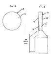
- Figure 1 shows one type of thermally stable polycrystalline diamond compact to which the present invention is applicable.
- the compact 10 is in the form of a cylinder of triangular cross-section, having a front cutting face 11 and a rear face 12.
- Such compacts are manufactured by placing a mass of particulate diamond material in a press in contact with a catalyst metal such as cobalt. The powder is then subject to extremely high temperatures and pressures resulting in catalysed re-crystallisation of the diamond particles to yield a compact characterised by diamond-to-diamond bonding.
- a catalyst metal such as cobalt
- the presence of the cobalt in such a compact would render the compact unstable at temperatures above about 700 to 750°C.
- the cobalt is leeched out after formation of the compact.
- Such compacts were mounted at the surface of a rotary drill bit in similar manner to the conventional methods used for natural diamonds.
- a rotary drill bit incorporating such thermally stable compacts is described and illustrated in Figure 1 of European Patent Specification No. 0,154,936 which is incorporated herein by reference.
- thermally stable compacts have also been manufactured in similar configurations to such non-thermally stable compacts, for example in the form of flat circular discs.
- Such compacts may also be used in a drill bit of generally similar form to that shown in the above-mentioned European Patent Specification No 0,154,936. It will be appreciated, however, that this European Specification illustrates only one example of the many possible variations of the type of bit to which the present invention is applicable.
- thermally stable compacts suffer from the disadvantage that, unlike two-layer and multi-layer compacts of similar shape, they are not self- sharpening
- a carrier of less hard material such as tungsten carbide
- such compacts are to be rendered self-sharpening by varying the composition of the compact itself across its thickness so that it is less wear resistant nearer the rear face than it is near the front cutting face.
- the grain size of the polycrystalline diamond particles used in the formation of the compact is varied across the thickness of the compact.
- the circular disc-like compact 13 has a front cutting face 14 and a rear face 15.
- the grain size of the particles is not greater than 10 micrometers whereas in the layer 17 adjacent the rear face 15 the maximum grain size is greater, for example in the range 75 to 500 micrometers.
- the wear resistance of polycrystalline diamond depends to a great extent on the size of the diamond particles A smaller maximum particle size in a diamond layer will result in greater wear resistance than a larger maximum particle size and thus the wear resistance of the front layer 16 will be greater than the wear resistance of the rear layer 17 with the result that the compact will be self-sharpening.
- the wear resistance may also be varied by varying the grain size distribution or packing density of the diamond particles.
- a mix having an appropriate range of different particle sizes will usually provide a higher packing density than a mix of comparatively uniformly sized particles, since the smaller particles will fill the voids between the larger particles.
- the grain size distribution for the different layers 16 and 17, or intermediate layers may be selected to provide the required variation of wear resistance across the thickness of the cutting element.
- the compact may be otherwise manufactured by the conventional process of subjecting the mass of diamond particles to high temperature and pressure in a press in combination with cobalt, the cobalt subsequently being leeched out to render the compact thermally stable.
- a catalyst metallic material which does not require to be leeched out in order to render the compact thermally stable.
- the metallic material may be silicon.
- the front layer will consist of diamond particles in a silicon carbide matrix derived from the silicon infiltrant. A little residual silicon will also remain.
- the proportion of silicon carbide will also decrease and the proportion of unreacted silicon metal will increase.
- silicon metal has a low thermal expansion coefficient and the presence of silicon is therefore less likely to cause thermal instability than the presence of cobalt. It is for the above reasons that the presence of silicon in the finished compact can be tolerated, since it does not render the compact non-thermally stable.
- Figures 4 and 5 show such an arrangemeent where the front layer 16 of the compact consists of 100% diamond particles whereas the rear layer 17 contains 50%, by volume, of an additive.
- the necessary properties of the additive are that it should be able to withstand the temperature and pressure to which it must be subjected in the press during formation of the compact, it should have a high Young ⁇ s modulus and fairly high strength and a low coefficient of expansion.
- the Young ⁇ s modulus of the material is preferably greater than 250 GPa
- the strength is preferably greater than 200 MPa
- the coefficient of thermal expansion is preferably less than 10 x 10 -6 /°C.
- Suitable additives may be metallic tungsten or other refractory metal or a ceramic such as boron carbide, silicon carbide, tantalum carbide, titanium carbide, titanium nitride, boron nitride or titanium boride.
- the additive is provided in addition to the catalyst metallic material, which material may either be leeched out as described above after formation of the compact, if it is a high coefficient of thermal expansion material such as cobalt, or may remain in the compact if it is a material of lower thermal coefficient of expansion such as silicon.
- the proportions of additive in the compact should be less than where leeching is not required since the presence of the additive may inhibit the leeching process by closing the pores in the material.
- Figures 6 and 7 show an alternative arrangement where the mass of polycrystalline diamond material is in three layers each containing a different amount of additive.
- the compact 18 comprises a front layer 19 adjacent the front cutting face 20 which contains no additive and is 100% diamond, an intermediate layer 21 which contains 40% additive by volume and a rear layer 22 which contains 60% additive by volume.
- Figures 8 and 9 show an alternative arrange ment where the proportions of additive in the diamond material vary substantially continuously across the thickness of the compact from 0% adjacent the front cutting face 24 to approximately 75% adjacent the rear face 25.
- the catalyst metallic material may be silicon or a silicon alloy.
- the alloy may be selected so as to react with the additive.
- the additive may be tungsten carbide and the silicon alloy may comprise 80% silicon and 20% titanium.
- any of the self-sharpening polycrystalline diamond compact cutting elements described above, or otherwise in accordance with the invention may be mounted on any suitable form of drill bit, such as a drill bit of the kind shown in the above-mentioned European Patent Specification No 0,154,936, incorporated herein by reference. Accordingly, the invention includes within its scope a drill bit having such compacts, as well as the compacts themselves.
Description
- The invention relates to cutting elements for rotary drill bits for use in drilling or coring deep holes in subsurface formations.
- Rotary drill bits of the kind to which the present invention is applicable comprise a bit body having a shank for connection to a drill string and an inner passage for supplying drilling fluid to the face of the bit. The bit body carries a plurality of so-called 'preform' cutting elements, Each cutting element may be mounted directly on the bit body or on a carrier, such as a stud or post, which is received in a socket in the bit body. One common form of preform cutting element is a polycrystalline diamond compact comprising a hard facing layer of polycrystalline diamond and a backing layer formed of cemented tungsten carbide. Since the backing layer is of less hard material than the facing layer, the two-layer arrangement of the cutting element provides a degree of self-sharpening since, in use, the less hard backing layer wears away more easily than the harder cutting layer.
- According to one known method of manufacturing such polycrystalline diamond compacts, as described for example in U.S. Patent Specifications Nos, 3,745,623, 3,609,818 and 3,850,591, a mass of polycrystalline diamond powder is placed in a press with a body of cemented tungsten carbide which is to form the backing layer of the finished compact. In contact with the diamond and/or carbide powder is a catalyst metal such as cobalt. The powder is then subjected to extremely high temperatures and pressures resulting in catalysed re-crystallisation of the diamond particles to yield a compact characterised by diamond-to-diamond bonding in the diamond layer, which diamond layer is bonded to the carbide backing layer.
- Diamond compacts manufactured according to such methods, however, have the disadvantage that they are only thermally stable up to temperatures of the order of 700° to 750°C.
- In one commonly used method of making rotary drill bits of the type first mentioned above, the bit body is formed by a powder metallurgy process in which tungsten carbide powder is infiltrated with a metal alloy binder in a furnace so as to form a hard matrix. The maximum furnace temperature required to form the matrix may be of the order of 1050-1170°C. Since, as mentioned above, conventional two-layer preform cutting elements are not thermally stable at such temperatures, they normally require to be mounted on the bit body after it has been formed, and this may be a time-consuming and costly process.
- There are, however, now available polycrystalline diamond compacts which are thermally stable up to the infiltration temperature, typically about 1100°C.
- Such thermally stable compact may be produced, for example, by leeching the cobalt out of compacts manufactured using a cobalt catalyst as described above, but without the tungsten carbide backing layer. Alternatively, use of other forms of catalyst, such as silicon or silicon carbide, instead of cobalt, may result in compacts which are thermally stable at the required temperature. Methods of producing such silicon bonded polycrystalline diamond compacts are described in detail, for example, in U.S. Patent Specifications Nos. 4,151,686 and 4,168,957. Such thermally stable elements may thus be located within the mould in which the bit body is formed so that they become mounted on the bit body in the furnace during the formation thereof. Such thermally stable elements may also have other advantages, for example they may be less costly to manufacture than two-layer cutting elements.
- Normally, thermally stable cutting elements have been in the form of blocks of uniform polycrystalline diamond material, and elements have also been made in similar shapes to two-layer cutting elements, e.g. in the form of circular tablets.
- Since conventional thermally stable cutting elements are uniform throughout their thickness, however, they do not provide the self-sharpening characteristic of two-layer or multi-layer cutting elements, and this may be a disadvantage particularly since the thermally stable elements may require to be thicker than the diamond layer of a two-layer element to provide the necessary mechanical strength. A degree of self-sharpening may be provided by bonding a thin thermally stable element, after formation, to a less wear resistant highly rigid support material but hitherto difficulties have been experienced in achieving effective bonding of thermally stable elements.
- The present invention sets out to overcome this problem by providing a thermally stable cutting element which is inherently self-sharpening by providing for the material nearer the rear face of the element to be less wear resistant than the material near the front cutting face of the element. The invention includes within its scope a number of alternative methods of achieving this effect.
- As disclosed in U.S. Patent Specification No. 4359335, the wear resistance of a sintered tungsten carbide product, for use in a drill bit, may be controlled by varying the grain size of the tungsten carbide and/or varying the amount of cobalt added to the tungsten carbide powder. Thus, the larger the tungsten carbide grain size and/or the more cobalt added to the tungsten carbide powder, the softer the sintered product. U.S. Patent Specification No. 4359335 utilises this concept in a non-thermally-stable rock bit insert, to provide a separately preformed harder wear pad on a softer main body of the insert.
- U.S. Patent Specification No. 4311490 discloses a method of manufacturing a polycrystalline diamond compact where a mass of diamond particles is located in a press in contact with a mass of metal carbide, the diamond particles being arranged in layers of varying coarseness such that the coarsest layer is closest to the carbide mass and the finest layer is disposed farthest away from the carbide mass. However, the object of the invention described in Specification No. 4311490 is merely to reduce the resistance to flow of catalyst metal or catalyst metal and carbide through the interstices in the diamond particles in the diamond layer.
- According to the invention there is provided a method of producing a self-sharpening thermally stable polycrystalline diamond compact comprising placing in a high pressure/high temperature apparatus a mass of polycrystalline diamond particles, said mass having a front face and a rear face, also placing in the apparatus, in contact with the mass of polycrystalline diamond particles, a mass of catalyst metallic material, and subjecting said masses to high pressure and temperature such that the metallic material infiltrates the mass of diamond particles so as to form, on subsequent cooling, a solid composite compact, said polycrystalline diamond compact being rendered thermally stable up to a temperature of about 1100°C by the use of silicon or a silicon alloy as the catalyst metallic material, or by the further step of leaching the catalyst metallic material from the solid composite compact, after formation, characterised in that the polycrystalline diamond particles nearer the rear face of the mass of particles are of larger maximum grain size than the particles nearer the front face thereof, so that the resulting thermally stable composite compact is less wear resistant nearer its rear face and is thereby self-sharpening in use.
- The self-sharpening effect is achieved as a result of the portions of the element nearer the rear face wearing away more easily, in use, than the portions nearer the front cutting face.
- The catalyst metallic material may be cobalt and may be leached from the solid composite compact after formation.
- The mass of polycrystalline diamond particles may comprise at least two contiguous layers of particles, a layer nearer the rear face being of greater maximum grain size than a layer nearer the front face. The polycrystalline diamond particles defining the front face of the mass of particles preferably have a maximum grain size less than 10 micrometers, and the particles defining the rear face preferably have a maximum grain size in the range of 75-500 micrometers.
- The packing density of the particles in the mass of polycrystalline particles may vary between said front face and rear face, material nearer the front face being of greater packing density than the material nearer the rear face.
- The invention also provides a method of producing a self-sharpening thermally stable polycrystalline diamond compact comprising placing in a high pressure/high temperature apparatus a mass of polycrystalline diamond particles, said mass having a front face and a rear face, also placing in the apparatus, in contact with the mass of polycrystalline diamond particles, a mass of catalyst metallic material, and subjecting said masses to high pressure and temperature such that the metallic material infiltrates the mass of diamond particles so as to form, on subsequent cooling, a solid composite compact, said polycrystalline diamond compact being rendered thermally stable up to a temperature of about 1100°C by the use of silicon or a silicon alloy as the catalyst metallic material, or by the further step of leaching the catalyst metallic material from the solid composite compact, after formation, characterised in that the mass of polycrystalline diamond particles also includes particles of an additive material selected from a refractory metal or a ceramic, a portion of the mass of particles nearer the rear face thereof including a higher proportion of said particles of additive material than a portion of the mass of particles nearer the front face thereof, so that the resulting thermally stable composite compact is less wear resistant nearer its rear face and is thereby self-sharpening in use.
- As in the previously described methods, the catalyst metallic material may be cobalt and may be leached from the solid composite compact after formation.
- The additive material may be tungsten, or may be selected from boron carbide, silicon carbide, tantalum carbide, tungsten carbide, titanium carbide, titanium nitride, boron nitride and titanium boride.
- The mass of polycrystalline diamond particles may comprise at least two contiguous layers of particles, a layer nearer the rear face having a higher proportion of said additive material than a layer nearer the front face. Preferably said layer nearer the front face includes from 0% to 5% of said additive material, by volume, and the layer nearer the rear face includes from 50% to 70% of said additive material, by volume.
- The invention further provides a self-sharpening thermally stable cutting element for use in a rotary drill bit comprising a polycrystalline diamond compact having a front face and a rear face, said polycrystalline diamond compact being rendered thermally stable up to a temperature of about 1100°C by the use of silicon or a silicon alloy as a catalyst metallic material during formation of the compact, or by leaching of the catalyst metallic material from the solid composite compact, after formation, characterised in that the polycrystalline diamond material nearer the front face of the compact is of smaller maximum grain size than material nearer the rear face so that the cutting element is less wear resistant nearer its rear face and is thereby self-sharpening in use.
- The packing density of the diamond particles in the body of polycrystalline diamond material may vary between said front face and rear face, material nearer the front face being of higher packing density than material nearer the rear face.
- The invention further provides a self-sharpening thermally stable cutting element for use in a rotary drill bit comprising a polycrystalline diamond compact having a front face and a rear face, said polycrystalline diamond compact being rendered thermally stable up to a temperature of about 1100°C by the use of silicon or a silicon alloy as a catalyst metallic material during formation of the compact, or by leaching of the catalyst metallic material from the solid composite compact, after formation, characterised in that the body of polycrystalline diamond material includes an additive material selected from a refractory metal or a ceramic, the proportion of additive material in the polycrystalline diamond varying between said front face and rear face in such manner that material nearer the rear face is less wear resistant than material nearer the front face, so that the cutting element is thereby self-sharpening in use.
- The additive material may be such that its presence decreases wear resistance, material nearer said front face including a lower proportion of said additive material than material nearer said rear face.
- The invention further provides a rotary drill bit for drilling or coring holes in subsurface formations comprising a bit body having a shank for connection to a drill string, an inner passage for supplying drilling fluid to the face of the bit, and a plurality of cutting elements mounted on the bit body, each cutting element comprising a polycrystalline diamond compact having a front face and a rear face, said polycrystalline diamond compact being rendered thermally stable up to a temperature of about 1100°C by the use of silicon or a silicon alloy as a catalyst metallic material during formation of the compact, or by leaching of the catalyst metallic material from the solid composite compact, after formation, characterised in that the polycrystalline diamond material nearer the front face of the compact is of smaller maximum grain size than material nearer the rear face so that the cutting element is less wear resistant nearer its rear face and is thereby self-sharpening in use of the drill bit.
- The following is a more detailed description of embodiments of the invention, reference being made to the accompanying drawings in which:
- Figure 1 is a diagrammatic perspective view of one form of thermally stable polycrystalline diamond compact.
- Figure 2 is a front view of an alternative form of compact.
- Figure 3 is a side view of the compact shown in Figure 2, combined with a graph showing the grain size distribution throughout the thickness of the compact, and
- Figures 4 and 5, Figures 6 and 7 and Figures 8 and 9 are similar views to Figures 2 and 3 respectively showing the proportions of additive in other polycrystalline diamond compacts according to the invention.
- Figure 1 shows one type of thermally stable polycrystalline diamond compact to which the present invention is applicable. In this case the compact 10 is in the form of a cylinder of triangular cross-section, having a front cutting face 11 and a rear face 12.
- Normally such compacts are manufactured by placing a mass of particulate diamond material in a press in contact with a catalyst metal such as cobalt. The powder is then subject to extremely high temperatures and pressures resulting in catalysed re-crystallisation of the diamond particles to yield a compact characterised by diamond-to-diamond bonding. However, the presence of the cobalt in such a compact would render the compact unstable at temperatures above about 700 to 750°C. In order to render the compact thermally stable at higher temperatures, therefore, the cobalt is leeched out after formation of the compact. Such compacts were mounted at the surface of a rotary drill bit in similar manner to the conventional methods used for natural diamonds. A rotary drill bit incorporating such thermally stable compacts is described and illustrated in Figure 1 of European Patent Specification No. 0,154,936 which is incorporated herein by reference.
- In an endeavour to obtain some of the advantages provided by the shapes of two layer, non- thermally stable polycrystalline diamond compacts, thermally stable compacts have also been manufactured in similar configurations to such non-thermally stable compacts, for example in the form of flat circular discs. Such compacts may also be used in a drill bit of generally similar form to that shown in the above-mentioned European Patent Specification No 0,154,936. It will be appreciated, however, that this European Specification illustrates only one example of the many possible variations of the type of bit to which the present invention is applicable.
- Known forms of thermally stable compacts suffer from the disadvantage that, unlike two-layer and multi-layer compacts of similar shape, they are not self- sharpening In order to provide a degree of self- sharpening in case of thin compacts of the kind shown for example in Figures 2 and 3, attempts have been made to mount such compacts on a carrier of less hard material, such as tungsten carbide, so that the lower wear resistance of the carrier material, behind the front cutting face provided by the compact itself, would give a degree of self-sharpening. However, difficulties have been encountered in mounting such thermally stable compacts on a carrier.
- According to the present invention, such compacts are to be rendered self-sharpening by varying the composition of the compact itself across its thickness so that it is less wear resistant nearer the rear face than it is near the front cutting face.
- According to one method of achieving this result, the grain size of the polycrystalline diamond particles used in the formation of the compact is varied across the thickness of the compact. For example, referring to Figures 2 and 3, the circular disc-like compact 13 has a
front cutting face 14 and arear face 15. In afront layer 16 of the compact the grain size of the particles is not greater than 10 micrometers whereas in thelayer 17 adjacent therear face 15 the maximum grain size is greater, for example in therange 75 to 500 micrometers. - The wear resistance of polycrystalline diamond depends to a great extent on the size of the diamond particles A smaller maximum particle size in a diamond layer will result in greater wear resistance than a larger maximum particle size and thus the wear resistance of the
front layer 16 will be greater than the wear resistance of therear layer 17 with the result that the compact will be self-sharpening. - Instead of only the two
layers - In addition to, or instead of, varying the wear resistance by varying the grain size, the wear resistance may also be varied by varying the grain size distribution or packing density of the diamond particles. Thus, a mix having an appropriate range of different particle sizes will usually provide a higher packing density than a mix of comparatively uniformly sized particles, since the smaller particles will fill the voids between the larger particles. Accordingly the grain size distribution for the
different layers - In such arrangements where the varying wear resistance is provided by varying the grain size and/or packing density of the diamond particles, the compact may be otherwise manufactured by the conventional process of subjecting the mass of diamond particles to high temperature and pressure in a press in combination with cobalt, the cobalt subsequently being leeched out to render the compact thermally stable. Alternatively, however, there may be used a catalyst metallic material which does not require to be leeched out in order to render the compact thermally stable. For example the metallic material may be silicon. In this case, in the
layer 16 adjacent the front cutting face, where the packing density of the diamond particles is greatest, the front layer will consist of diamond particles in a silicon carbide matrix derived from the silicon infiltrant. A little residual silicon will also remain. In the more rearward layer or layers, where the packing density of the diamond particles is less, the proportion of silicon carbide will also decrease and the proportion of unreacted silicon metal will increase. Unlike cobalt, however, silicon metal has a low thermal expansion coefficient and the presence of silicon is therefore less likely to cause thermal instability than the presence of cobalt. It is for the above reasons that the presence of silicon in the finished compact can be tolerated, since it does not render the compact non-thermally stable. - As previously mentioned, in an alternative method of varying the wear resistance of the finished diamond compact, this is achieved by including with the diamond material in the press an additive which alters the wear resistance, the proportion of additive varying across the thickness of the compact.
- Figures 4 and 5 show such an arrangemeent where the
front layer 16 of the compact consists of 100% diamond particles whereas therear layer 17 contains 50%, by volume, of an additive. The necessary properties of the additive are that it should be able to withstand the temperature and pressure to which it must be subjected in the press during formation of the compact, it should have a high Youngʹs modulus and fairly high strength and a low coefficient of expansion. For example, the Youngʹs modulus of the material is preferably greater than 250 GPa, the strength is preferably greater than 200 MPa, and the coefficient of thermal expansion is preferably less than 10 x 10-6/°C. - Suitable additives may be metallic tungsten or other refractory metal or a ceramic such as boron carbide, silicon carbide, tantalum carbide, titanium carbide, titanium nitride, boron nitride or titanium boride.
- In the manufacture of the polycrystalline diamond compact, the additive is provided in addition to the catalyst metallic material, which material may either be leeched out as described above after formation of the compact, if it is a high coefficient of thermal expansion material such as cobalt, or may remain in the compact if it is a material of lower thermal coefficient of expansion such as silicon.
- Generally speaking, if it is necessary to leech the catalyst material from the finished compact, the proportions of additive in the compact should be less than where leeching is not required since the presence of the additive may inhibit the leeching process by closing the pores in the material.
- Figures 6 and 7 show an alternative arrangement where the mass of polycrystalline diamond material is in three layers each containing a different amount of additive. Thus, the compact 18 comprises a
front layer 19 adjacent the front cutting face 20 which contains no additive and is 100% diamond, anintermediate layer 21 which contains 40% additive by volume and arear layer 22 which contains 60% additive by volume. - Figures 8 and 9 show an alternative arrange ment where the proportions of additive in the diamond material vary substantially continuously across the thickness of the compact from 0% adjacent the front cutting face 24 to approximately 75% adjacent the
rear face 25. - As mentioned above, the catalyst metallic material may be silicon or a silicon alloy. In the case of a silicon alloy the alloy may be selected so as to react with the additive.
- For example, the additive may be tungsten carbide and the silicon alloy may comprise 80% silicon and 20% titanium.
- Any of the self-sharpening polycrystalline diamond compact cutting elements described above, or otherwise in accordance with the invention, may be mounted on any suitable form of drill bit, such as a drill bit of the kind shown in the above-mentioned European Patent Specification No 0,154,936, incorporated herein by reference. Accordingly, the invention includes within its scope a drill bit having such compacts, as well as the compacts themselves.
Claims (17)
Applications Claiming Priority (2)
| Application Number | Priority Date | Filing Date | Title |
|---|---|---|---|
| GB858505352A GB8505352D0 (en) | 1985-03-01 | 1985-03-01 | Cutting elements |
| GB8505352 | 1985-03-01 |
Publications (2)
| Publication Number | Publication Date |
|---|---|
| EP0196777A1 EP0196777A1 (en) | 1986-10-08 |
| EP0196777B1 true EP0196777B1 (en) | 1991-03-06 |
Family
ID=10575298
Family Applications (1)
| Application Number | Title | Priority Date | Filing Date |
|---|---|---|---|
| EP86301412A Expired - Lifetime EP0196777B1 (en) | 1985-03-01 | 1986-02-27 | Improvements in or relating to cutting elements for rotary drill bits |
Country Status (7)
| Country | Link |
|---|---|
| EP (1) | EP0196777B1 (en) |
| JP (1) | JPS61270496A (en) |
| CA (1) | CA1258849A (en) |
| DE (1) | DE3677805D1 (en) |
| GB (1) | GB8505352D0 (en) |
| IE (1) | IE57436B1 (en) |
| ZA (1) | ZA861407B (en) |
Cited By (22)
| Publication number | Priority date | Publication date | Assignee | Title |
|---|---|---|---|---|
| US7647993B2 (en) | 2004-05-06 | 2010-01-19 | Smith International, Inc. | Thermally stable diamond bonded materials and compacts |
| US7681669B2 (en) | 2005-01-17 | 2010-03-23 | Us Synthetic Corporation | Polycrystalline diamond insert, drill bit including same, and method of operation |
| US7726421B2 (en) | 2005-10-12 | 2010-06-01 | Smith International, Inc. | Diamond-bonded bodies and compacts with improved thermal stability and mechanical strength |
| US7757791B2 (en) | 2005-01-25 | 2010-07-20 | Smith International, Inc. | Cutting elements formed from ultra hard materials having an enhanced construction |
| US7980334B2 (en) | 2007-10-04 | 2011-07-19 | Smith International, Inc. | Diamond-bonded constructions with improved thermal and mechanical properties |
| US8057562B2 (en) | 2006-02-09 | 2011-11-15 | Smith International, Inc. | Thermally stable ultra-hard polycrystalline materials and compacts |
| US8083012B2 (en) | 2008-10-03 | 2011-12-27 | Smith International, Inc. | Diamond bonded construction with thermally stable region |
| US8309050B2 (en) | 2005-05-26 | 2012-11-13 | Smith International, Inc. | Polycrystalline diamond materials having improved abrasion resistance, thermal stability and impact resistance |
| US8377157B1 (en) | 2009-04-06 | 2013-02-19 | Us Synthetic Corporation | Superabrasive articles and methods for removing interstitial materials from superabrasive materials |
| CN103015903A (en) * | 2012-12-03 | 2013-04-03 | 中国地质大学(武汉) | Fabrication method for hot pressing diamond bit with added aluminium oxide hollow balls |
| US8499861B2 (en) | 2007-09-18 | 2013-08-06 | Smith International, Inc. | Ultra-hard composite constructions comprising high-density diamond surface |
| US8590130B2 (en) | 2009-05-06 | 2013-11-26 | Smith International, Inc. | Cutting elements with re-processed thermally stable polycrystalline diamond cutting layers, bits incorporating the same, and methods of making the same |
| US8771389B2 (en) | 2009-05-06 | 2014-07-08 | Smith International, Inc. | Methods of making and attaching TSP material for forming cutting elements, cutting elements having such TSP material and bits incorporating such cutting elements |
| US8783389B2 (en) | 2009-06-18 | 2014-07-22 | Smith International, Inc. | Polycrystalline diamond cutting elements with engineered porosity and method for manufacturing such cutting elements |
| US8881851B2 (en) | 2003-12-05 | 2014-11-11 | Smith International, Inc. | Thermally-stable polycrystalline diamond materials and compacts |
| US8936659B2 (en) | 2010-04-14 | 2015-01-20 | Baker Hughes Incorporated | Methods of forming diamond particles having organic compounds attached thereto and compositions thereof |
| US8951317B1 (en) | 2009-04-27 | 2015-02-10 | Us Synthetic Corporation | Superabrasive elements including ceramic coatings and methods of leaching catalysts from superabrasive elements |
| US9140072B2 (en) | 2013-02-28 | 2015-09-22 | Baker Hughes Incorporated | Cutting elements including non-planar interfaces, earth-boring tools including such cutting elements, and methods of forming cutting elements |
| US9144886B1 (en) | 2011-08-15 | 2015-09-29 | Us Synthetic Corporation | Protective leaching cups, leaching trays, and methods for processing superabrasive elements using protective leaching cups and leaching trays |
| US9352447B2 (en) | 2009-09-08 | 2016-05-31 | Us Synthetic Corporation | Superabrasive elements and methods for processing and manufacturing the same using protective layers |
| US9550276B1 (en) | 2013-06-18 | 2017-01-24 | Us Synthetic Corporation | Leaching assemblies, systems, and methods for processing superabrasive elements |
| US10900291B2 (en) | 2017-09-18 | 2021-01-26 | Us Synthetic Corporation | Polycrystalline diamond elements and systems and methods for fabricating the same |
Families Citing this family (24)
| Publication number | Priority date | Publication date | Assignee | Title |
|---|---|---|---|---|
| EP0219959B1 (en) * | 1985-10-18 | 1992-04-29 | Smith International, Inc. | Rock bit with wear resistant inserts |
| WO1999012866A1 (en) | 1997-09-05 | 1999-03-18 | Frenton Limited | Method of manufacturing a diamond-silicon carbide-silicon composite and a composite produced by this method |
| US6709747B1 (en) * | 1998-09-28 | 2004-03-23 | Skeleton Technologies Ag | Method of manufacturing a diamond composite and a composite produced by same |
| US8016054B2 (en) | 2003-05-27 | 2011-09-13 | Brett Lancaster | Polycrystalline diamond abrasive elements |
| US7575805B2 (en) * | 2003-12-11 | 2009-08-18 | Roy Derrick Achilles | Polycrystalline diamond abrasive elements |
| US7497280B2 (en) * | 2005-01-27 | 2009-03-03 | Baker Hughes Incorporated | Abrasive-impregnated cutting structure having anisotropic wear resistance and drag bit including same |
| US7694757B2 (en) * | 2005-02-23 | 2010-04-13 | Smith International, Inc. | Thermally stable polycrystalline diamond materials, cutting elements incorporating the same and bits incorporating such cutting elements |
| US9097074B2 (en) | 2006-09-21 | 2015-08-04 | Smith International, Inc. | Polycrystalline diamond composites |
| US8028771B2 (en) | 2007-02-06 | 2011-10-04 | Smith International, Inc. | Polycrystalline diamond constructions having improved thermal stability |
| US7942219B2 (en) | 2007-03-21 | 2011-05-17 | Smith International, Inc. | Polycrystalline diamond constructions having improved thermal stability |
| US8627904B2 (en) | 2007-10-04 | 2014-01-14 | Smith International, Inc. | Thermally stable polycrystalline diamond material with gradient structure |
| US9297211B2 (en) | 2007-12-17 | 2016-03-29 | Smith International, Inc. | Polycrystalline diamond construction with controlled gradient metal content |
| US8365846B2 (en) * | 2009-03-27 | 2013-02-05 | Varel International, Ind., L.P. | Polycrystalline diamond cutter with high thermal conductivity |
| US8505654B2 (en) | 2009-10-09 | 2013-08-13 | Element Six Limited | Polycrystalline diamond |
| WO2011084645A1 (en) * | 2009-12-16 | 2011-07-14 | Smith International, Inc. | Thermally stable diamond bonded materials and compacts |
| RU2559183C2 (en) | 2010-04-28 | 2015-08-10 | Бейкер Хьюз Инкорпорейтед | Polycrystalline diamond elements, cutting tools and drilling tools including such elements as well as production of such elements and drills |
| US8978734B2 (en) | 2010-05-20 | 2015-03-17 | Baker Hughes Incorporated | Methods of forming at least a portion of earth-boring tools, and articles formed by such methods |
| US9789587B1 (en) | 2013-12-16 | 2017-10-17 | Us Synthetic Corporation | Leaching assemblies, systems, and methods for processing superabrasive elements |
| US10807913B1 (en) | 2014-02-11 | 2020-10-20 | Us Synthetic Corporation | Leached superabrasive elements and leaching systems methods and assemblies for processing superabrasive elements |
| US9908215B1 (en) | 2014-08-12 | 2018-03-06 | Us Synthetic Corporation | Systems, methods and assemblies for processing superabrasive materials |
| US11766761B1 (en) | 2014-10-10 | 2023-09-26 | Us Synthetic Corporation | Group II metal salts in electrolytic leaching of superabrasive materials |
| US10011000B1 (en) | 2014-10-10 | 2018-07-03 | Us Synthetic Corporation | Leached superabrasive elements and systems, methods and assemblies for processing superabrasive materials |
| US10723626B1 (en) | 2015-05-31 | 2020-07-28 | Us Synthetic Corporation | Leached superabrasive elements and systems, methods and assemblies for processing superabrasive materials |
| EP3341342B1 (en) * | 2015-08-26 | 2020-11-11 | Sandvik Intellectual Property AB | Diamond composites by lithography-based manufacturing |
Family Cites Families (5)
| Publication number | Priority date | Publication date | Assignee | Title |
|---|---|---|---|---|
| US3745623A (en) * | 1971-12-27 | 1973-07-17 | Gen Electric | Diamond tools for machining |
| US4151686A (en) * | 1978-01-09 | 1979-05-01 | General Electric Company | Silicon carbide and silicon bonded polycrystalline diamond body and method of making it |
| US4288248A (en) * | 1978-03-28 | 1981-09-08 | General Electric Company | Temperature resistant abrasive compact and method for making same |
| US4359335A (en) * | 1980-06-05 | 1982-11-16 | Smith International, Inc. | Method of fabrication of rock bit inserts of tungsten carbide (WC) and cobalt (Co) with cutting surface wear pad of relative hardness and body portion of relative toughness sintered as an integral composite |
| US4311490A (en) * | 1980-12-22 | 1982-01-19 | General Electric Company | Diamond and cubic boron nitride abrasive compacts using size selective abrasive particle layers |
-
1985
- 1985-03-01 GB GB858505352A patent/GB8505352D0/en active Pending
-
1986
- 1986-02-25 ZA ZA861407A patent/ZA861407B/en unknown
- 1986-02-27 EP EP86301412A patent/EP0196777B1/en not_active Expired - Lifetime
- 1986-02-27 DE DE8686301412T patent/DE3677805D1/en not_active Expired - Lifetime
- 1986-02-28 IE IE545/86A patent/IE57436B1/en not_active IP Right Cessation
- 1986-02-28 JP JP61043888A patent/JPS61270496A/en active Pending
- 1986-03-03 CA CA000503083A patent/CA1258849A/en not_active Expired
Cited By (28)
| Publication number | Priority date | Publication date | Assignee | Title |
|---|---|---|---|---|
| US8881851B2 (en) | 2003-12-05 | 2014-11-11 | Smith International, Inc. | Thermally-stable polycrystalline diamond materials and compacts |
| US8852304B2 (en) | 2004-05-06 | 2014-10-07 | Smith International, Inc. | Thermally stable diamond bonded materials and compacts |
| US7647993B2 (en) | 2004-05-06 | 2010-01-19 | Smith International, Inc. | Thermally stable diamond bonded materials and compacts |
| US7681669B2 (en) | 2005-01-17 | 2010-03-23 | Us Synthetic Corporation | Polycrystalline diamond insert, drill bit including same, and method of operation |
| US7874383B1 (en) | 2005-01-17 | 2011-01-25 | Us Synthetic Corporation | Polycrystalline diamond insert, drill bit including same, and method of operation |
| US7757791B2 (en) | 2005-01-25 | 2010-07-20 | Smith International, Inc. | Cutting elements formed from ultra hard materials having an enhanced construction |
| US8309050B2 (en) | 2005-05-26 | 2012-11-13 | Smith International, Inc. | Polycrystalline diamond materials having improved abrasion resistance, thermal stability and impact resistance |
| US8932376B2 (en) | 2005-10-12 | 2015-01-13 | Smith International, Inc. | Diamond-bonded bodies and compacts with improved thermal stability and mechanical strength |
| US7726421B2 (en) | 2005-10-12 | 2010-06-01 | Smith International, Inc. | Diamond-bonded bodies and compacts with improved thermal stability and mechanical strength |
| US8057562B2 (en) | 2006-02-09 | 2011-11-15 | Smith International, Inc. | Thermally stable ultra-hard polycrystalline materials and compacts |
| US8499861B2 (en) | 2007-09-18 | 2013-08-06 | Smith International, Inc. | Ultra-hard composite constructions comprising high-density diamond surface |
| US7980334B2 (en) | 2007-10-04 | 2011-07-19 | Smith International, Inc. | Diamond-bonded constructions with improved thermal and mechanical properties |
| US8365844B2 (en) | 2008-10-03 | 2013-02-05 | Smith International, Inc. | Diamond bonded construction with thermally stable region |
| US8083012B2 (en) | 2008-10-03 | 2011-12-27 | Smith International, Inc. | Diamond bonded construction with thermally stable region |
| US8741005B1 (en) | 2009-04-06 | 2014-06-03 | Us Synthetic Corporation | Superabrasive articles and methods for removing interstitial materials from superabrasive materials |
| US8377157B1 (en) | 2009-04-06 | 2013-02-19 | Us Synthetic Corporation | Superabrasive articles and methods for removing interstitial materials from superabrasive materials |
| US8951317B1 (en) | 2009-04-27 | 2015-02-10 | Us Synthetic Corporation | Superabrasive elements including ceramic coatings and methods of leaching catalysts from superabrasive elements |
| US8590130B2 (en) | 2009-05-06 | 2013-11-26 | Smith International, Inc. | Cutting elements with re-processed thermally stable polycrystalline diamond cutting layers, bits incorporating the same, and methods of making the same |
| US8771389B2 (en) | 2009-05-06 | 2014-07-08 | Smith International, Inc. | Methods of making and attaching TSP material for forming cutting elements, cutting elements having such TSP material and bits incorporating such cutting elements |
| US8783389B2 (en) | 2009-06-18 | 2014-07-22 | Smith International, Inc. | Polycrystalline diamond cutting elements with engineered porosity and method for manufacturing such cutting elements |
| US9352447B2 (en) | 2009-09-08 | 2016-05-31 | Us Synthetic Corporation | Superabrasive elements and methods for processing and manufacturing the same using protective layers |
| US8936659B2 (en) | 2010-04-14 | 2015-01-20 | Baker Hughes Incorporated | Methods of forming diamond particles having organic compounds attached thereto and compositions thereof |
| US9144886B1 (en) | 2011-08-15 | 2015-09-29 | Us Synthetic Corporation | Protective leaching cups, leaching trays, and methods for processing superabrasive elements using protective leaching cups and leaching trays |
| CN103015903A (en) * | 2012-12-03 | 2013-04-03 | 中国地质大学(武汉) | Fabrication method for hot pressing diamond bit with added aluminium oxide hollow balls |
| US9140072B2 (en) | 2013-02-28 | 2015-09-22 | Baker Hughes Incorporated | Cutting elements including non-planar interfaces, earth-boring tools including such cutting elements, and methods of forming cutting elements |
| US9550276B1 (en) | 2013-06-18 | 2017-01-24 | Us Synthetic Corporation | Leaching assemblies, systems, and methods for processing superabrasive elements |
| US10900291B2 (en) | 2017-09-18 | 2021-01-26 | Us Synthetic Corporation | Polycrystalline diamond elements and systems and methods for fabricating the same |
| US11946320B2 (en) | 2017-09-18 | 2024-04-02 | Us Synthetic Corporation | Polycrystalline diamond elements and systems and methods for fabricating the same |
Also Published As
| Publication number | Publication date |
|---|---|
| JPS61270496A (en) | 1986-11-29 |
| GB8505352D0 (en) | 1985-04-03 |
| DE3677805D1 (en) | 1991-04-11 |
| IE57436B1 (en) | 1992-09-09 |
| EP0196777A1 (en) | 1986-10-08 |
| IE860545L (en) | 1986-09-01 |
| ZA861407B (en) | 1986-10-29 |
| CA1258849A (en) | 1989-08-29 |
Similar Documents
| Publication | Publication Date | Title |
|---|---|---|
| EP0196777B1 (en) | Improvements in or relating to cutting elements for rotary drill bits | |
| EP0157278B1 (en) | Multi-component cutting element using polycrystalline diamond disks | |
| US7234550B2 (en) | Bits and cutting structures | |
| EP1081119B1 (en) | Cutting elements and methods of manufacture thereof | |
| US8372334B2 (en) | Method of making diamond-bonded constructions with improved thermal and mechanical properties | |
| US6170583B1 (en) | Inserts and compacts having coated or encrusted cubic boron nitride particles | |
| US6725953B2 (en) | Drill bit having diamond impregnated inserts primary cutting structure | |
| US5199832A (en) | Multi-component cutting element using polycrystalline diamond disks | |
| EP0643792B1 (en) | Rolling cone bit with wear resistant insert | |
| EP0411831B1 (en) | Cutting element for rotary drill bit with multilayer cutting surface | |
| US4780274A (en) | Manufacture of rotary drill bits | |
| US5355750A (en) | Rolling cone bit with improved wear resistant inserts | |
| US4804049A (en) | Rotary drill bits | |
| GB2447776A (en) | Polycrystalline diamond bodies with a catalyst free region | |
| US20050230150A1 (en) | Coated diamonds for use in impregnated diamond bits | |
| GB2479273A (en) | Diamond body and a method for its manufacture | |
| GB2488713A (en) | Polycrystalline diamond construction with controlled gradient metal content | |
| EP0156264B1 (en) | Multi-component cutting element using triangular, rectangular and higher order polyhedral-shaped polycrystalline diamond disks | |
| CA2584928C (en) | Drill bit having diamond impregnated inserts primary cutting structure | |
| GB2404406A (en) | Novel bits and cutting structures | |
| CN109906303A (en) | Rock cutting tool and method for mine and oil drilling |
Legal Events
| Date | Code | Title | Description |
|---|---|---|---|
| PUAI | Public reference made under article 153(3) epc to a published international application that has entered the european phase |
Free format text: ORIGINAL CODE: 0009012 |
|
| AK | Designated contracting states |
Kind code of ref document: A1 Designated state(s): BE CH DE FR GB LI NL SE |
|
| 17P | Request for examination filed |
Effective date: 19870224 |
|
| 17Q | First examination report despatched |
Effective date: 19880518 |
|
| RAP1 | Party data changed (applicant data changed or rights of an application transferred) |
Owner name: REED TOOL COMPANY LIMITED |
|
| GRAA | (expected) grant |
Free format text: ORIGINAL CODE: 0009210 |
|
| AK | Designated contracting states |
Kind code of ref document: B1 Designated state(s): BE CH DE FR GB LI NL SE |
|
| PG25 | Lapsed in a contracting state [announced via postgrant information from national office to epo] |
Ref country code: SE Effective date: 19910306 Ref country code: LI Effective date: 19910306 Ref country code: CH Effective date: 19910306 |
|
| REF | Corresponds to: |
Ref document number: 3677805 Country of ref document: DE Date of ref document: 19910411 |
|
| ET | Fr: translation filed | ||
| REG | Reference to a national code |
Ref country code: CH Ref legal event code: PL |
|
| PLBE | No opposition filed within time limit |
Free format text: ORIGINAL CODE: 0009261 |
|
| STAA | Information on the status of an ep patent application or granted ep patent |
Free format text: STATUS: NO OPPOSITION FILED WITHIN TIME LIMIT |
|
| 26N | No opposition filed | ||
| PGFP | Annual fee paid to national office [announced via postgrant information from national office to epo] |
Ref country code: FR Payment date: 19930209 Year of fee payment: 8 |
|
| PGFP | Annual fee paid to national office [announced via postgrant information from national office to epo] |
Ref country code: GB Payment date: 19930217 Year of fee payment: 8 |
|
| PGFP | Annual fee paid to national office [announced via postgrant information from national office to epo] |
Ref country code: NL Payment date: 19930228 Year of fee payment: 8 |
|
| PGFP | Annual fee paid to national office [announced via postgrant information from national office to epo] |
Ref country code: DE Payment date: 19930308 Year of fee payment: 8 |
|
| PGFP | Annual fee paid to national office [announced via postgrant information from national office to epo] |
Ref country code: BE Payment date: 19930330 Year of fee payment: 8 |
|
| PG25 | Lapsed in a contracting state [announced via postgrant information from national office to epo] |
Ref country code: GB Effective date: 19940227 |
|
| PG25 | Lapsed in a contracting state [announced via postgrant information from national office to epo] |
Ref country code: BE Effective date: 19940228 |
|
| BERE | Be: lapsed |
Owner name: REED TOOL CY LTD Effective date: 19940228 |
|
| PG25 | Lapsed in a contracting state [announced via postgrant information from national office to epo] |
Ref country code: NL Effective date: 19940901 |
|
| NLV4 | Nl: lapsed or anulled due to non-payment of the annual fee | ||
| GBPC | Gb: european patent ceased through non-payment of renewal fee |
Effective date: 19940227 |
|
| PG25 | Lapsed in a contracting state [announced via postgrant information from national office to epo] |
Ref country code: FR Effective date: 19941031 |
|
| PG25 | Lapsed in a contracting state [announced via postgrant information from national office to epo] |
Ref country code: DE Effective date: 19941101 |
|
| REG | Reference to a national code |
Ref country code: FR Ref legal event code: ST |