EP0197555B1 - Steam generator - Google Patents
Steam generator Download PDFInfo
- Publication number
- EP0197555B1 EP0197555B1 EP86104859A EP86104859A EP0197555B1 EP 0197555 B1 EP0197555 B1 EP 0197555B1 EP 86104859 A EP86104859 A EP 86104859A EP 86104859 A EP86104859 A EP 86104859A EP 0197555 B1 EP0197555 B1 EP 0197555B1
- Authority
- EP
- European Patent Office
- Prior art keywords
- reaction chamber
- steam generator
- generator according
- outlet
- chamber
- Prior art date
- Legal status (The legal status is an assumption and is not a legal conclusion. Google has not performed a legal analysis and makes no representation as to the accuracy of the status listed.)
- Expired - Lifetime
Links
- 238000006243 chemical reaction Methods 0.000 claims description 67
- XLYOFNOQVPJJNP-UHFFFAOYSA-N water Substances O XLYOFNOQVPJJNP-UHFFFAOYSA-N 0.000 claims description 51
- 238000002347 injection Methods 0.000 claims description 27
- 239000007924 injection Substances 0.000 claims description 27
- 239000000203 mixture Substances 0.000 claims description 18
- 238000001816 cooling Methods 0.000 claims description 11
- 239000007789 gas Substances 0.000 claims description 10
- 239000001301 oxygen Substances 0.000 claims description 5
- 229910052760 oxygen Inorganic materials 0.000 claims description 5
- 239000011148 porous material Substances 0.000 claims description 4
- 239000002184 metal Substances 0.000 claims description 3
- UFHFLCQGNIYNRP-UHFFFAOYSA-N Hydrogen Chemical compound [H][H] UFHFLCQGNIYNRP-UHFFFAOYSA-N 0.000 claims description 2
- QVGXLLKOCUKJST-UHFFFAOYSA-N atomic oxygen Chemical compound [O] QVGXLLKOCUKJST-UHFFFAOYSA-N 0.000 claims description 2
- 239000001257 hydrogen Substances 0.000 claims description 2
- 229910052739 hydrogen Inorganic materials 0.000 claims description 2
- 230000008016 vaporization Effects 0.000 claims 8
- 238000009834 vaporization Methods 0.000 claims 8
- 239000007788 liquid Substances 0.000 description 10
- 238000001704 evaporation Methods 0.000 description 8
- 230000008020 evaporation Effects 0.000 description 8
- 238000002485 combustion reaction Methods 0.000 description 4
- 239000000498 cooling water Substances 0.000 description 3
- 239000002737 fuel gas Substances 0.000 description 3
- 238000000265 homogenisation Methods 0.000 description 3
- 230000001954 sterilising effect Effects 0.000 description 3
- 238000011144 upstream manufacturing Methods 0.000 description 3
- 238000009835 boiling Methods 0.000 description 2
- 230000006835 compression Effects 0.000 description 2
- 238000007906 compression Methods 0.000 description 2
- 238000010438 heat treatment Methods 0.000 description 2
- 238000000034 method Methods 0.000 description 2
- 238000001208 nuclear magnetic resonance pulse sequence Methods 0.000 description 2
- 238000004806 packaging method and process Methods 0.000 description 2
- 239000002245 particle Substances 0.000 description 2
- 239000000243 solution Substances 0.000 description 2
- 230000002269 spontaneous effect Effects 0.000 description 2
- 230000015572 biosynthetic process Effects 0.000 description 1
- 239000007795 chemical reaction product Substances 0.000 description 1
- 230000000694 effects Effects 0.000 description 1
- 239000003546 flue gas Substances 0.000 description 1
- 239000002803 fossil fuel Substances 0.000 description 1
- 239000000446 fuel Substances 0.000 description 1
- 238000013021 overheating Methods 0.000 description 1
- 239000000376 reactant Substances 0.000 description 1
- 238000004659 sterilization and disinfection Methods 0.000 description 1
Images


Classifications
-
- F—MECHANICAL ENGINEERING; LIGHTING; HEATING; WEAPONS; BLASTING
- F22—STEAM GENERATION
- F22B—METHODS OF STEAM GENERATION; STEAM BOILERS
- F22B1/00—Methods of steam generation characterised by form of heating method
- F22B1/003—Methods of steam generation characterised by form of heating method using combustion of hydrogen with oxygen
-
- F—MECHANICAL ENGINEERING; LIGHTING; HEATING; WEAPONS; BLASTING
- F22—STEAM GENERATION
- F22B—METHODS OF STEAM GENERATION; STEAM BOILERS
- F22B3/00—Other methods of steam generation; Steam boilers not provided for in other groups of this subclass
- F22B3/04—Other methods of steam generation; Steam boilers not provided for in other groups of this subclass by drop in pressure of high-pressure hot water within pressure- reducing chambers, e.g. in accumulators
Definitions
- the invention relates to a steam generator with the features specified in the preamble of claim 1.
- a steam generator is also known, in which the water supplied is fed in practically under the same pressure that prevails in the reaction space (DE-A-2 426 872).
- the cooling water is heated and evaporated in an outer shell surrounding the annular space and flows as pure water vapor through an inner shell directly adjacent to the annular space to the injection openings. Effective cooling of the annular space cannot be achieved, since only vaporous water flows directly adjacent to the annular space.
- the steam generator described is a large device with which steam at very high temperatures is generated at high pressure. It is only suitable for this purpose, but cannot be used for steam generators of small dimensions, for example for steam generators in the order of 15 cm in length and for low pressures in the order of 2 to 15 bar. In addition, the vaporous flow around the reaction chamber does not offer any adequate cooling for the walls of the reaction space.
- the object of the invention is, on the one hand, to obtain the shortest possible design of an evaporator and, on the other hand, to ensure that a steam generator is created which generates the purest possible water vapor, the water vapor containing neither unburned reactants nor liquid water particles should be.
- the evaporator chamber comprises an inner annular space which is directly connected to the reaction chamber and an outer annular space which is connected downstream thereof and is also arranged coaxially to the reaction chamber and that the flow restriction is arranged between the two annular spaces.
- This different flow rate promotes the evaporation process of the water droplets, so that this throttling in the area of the injection openings and a subsequent throttling also promote the homogenization of the steam.
- the constriction also acts as a throttle, so that the relaxation that occurs when flowing through the throttle, which can lead, for example, to a halving of the water vapor pressure, results in spontaneous evaporation of particles that are still liquid.
- cooling channels surround the reaction chamber in a helical shape, which results in a particularly long heating time for the cooling water in the wall of the reaction chamber.
- injection openings are directed in the reaction chamber counter to the direction of flow of the reaction gases.
- the injection openings are part of a swirl nozzle, into which the cooling channels open so eccentrically that the steam-water mixture is set in rotation before being injected into the reaction chamber.
- the injection openings and at least partly the cooling channels are formed by the pores of a porous injection body surrounding the reaction chamber, for example by a sintered metal tube.
- the evaporator chamber can be connected to a steam consumer via an outlet with a reduced flow cross section.
- the cross section can be designed in such a way that the pressure of the emerging steam is adapted to the respective requirements.
- the steam generator described can be used particularly advantageously for generating water vapor pulses, such as those used for sterilizing the contents of cans. It can do this be seen that the evaporator room can be connected to a steam consumer via an intermittently closable outlet, for example a sterilizing station in a canned packaging system.
- the outlet is closed by means of a spring-loaded outlet valve which, when a certain pressure of the water vapor in the evaporator chamber is exceeded, can be moved into the open position against the action of a spring.
- the outlet is provided by means of an outlet valve which can be actuated by an actuator and that a pressure sensor is arranged in the evaporator chamber which, when a certain pressure in the evaporator chamber is exceeded, supplies a control which leads to the opening of the outlet valve.
- the outlet valve can then either remain open for a certain period of time, or it is provided that the valve is closed again via the control when the pressure in the evaporator chamber falls below a certain value.
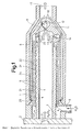
- the steam generator shown in FIG. 1 comprises a cylindrical, elongated reaction chamber 1 with a closed end wall 2, which has a central inlet opening 3. This is connected to an injection and ignition element, not shown in the drawing, which produces an ignitable hydrogen-oxygen mixture and introduces it into the reaction chamber 1.
- This ignitable gas mixture is ignited in the ignition device, not shown in the drawing, so that it reacts inside the reaction chamber 1 with the formation of superheated steam.
- the reaction product is pure water vapor.
- axially parallel channels 5 with a small cross section run which are connected to an annular space 7, which is arranged at the upstream end of the reaction chamber 1 and has a water inlet 6.
- These water channels can be discrete channels distributed over the circumference, the channels can also be formed by an annular gap surrounding the reaction chamber, in which case the inner wall and the outer wall. the reaction chamber are connected to one another via the webs not shown in the drawing.
- the channels 5 surround the inner wall of the reaction chamber 1 helically.
- the outer wall of the reaction chamber can carry a thread, over which a sleeve 21 is slid, which lies tightly against the individual threads and thereby forms a helical channel.
- the channels 5 open at the downstream end of the reaction chamber into a further annular space 8, from which emerges a channel 9 which runs obliquely to the longitudinal axis of the reaction chamber and which enters a swirl nozzle 10 in the closed end wall 11 of the reaction chamber 1.
- the swirl nozzle is concentric with the reaction chamber 1 arranged and has a rotationally symmetrical cavity 12 into which the channel 9 enters eccentrically such that medium flowing into the cavity is set in rotation about the longitudinal axis of the swirl nozzle.
- the cavity 12 is connected via a centrally arranged injection opening to the interior of the reaction chamber 1, so that the water emerging from the cavity 12 against the gas flow direction in the reaction chamber is injected into the reaction chamber in the form of a rotationally symmetrical veil 14, whereby the injected water applies to the inner wall of the reaction chamber and additionally cools it.
- the reaction chamber 1 is surrounded by an annular space 22 which extends over its entire length and is arranged coaxially to the reaction chamber 1. It is connected via radial channels 23 to the downstream end of the reaction chamber 1 which is closed by the end wall 11.
- the annular space 22 is in turn surrounded by another annular space 24, which is also arranged coaxially with the reaction chamber 1.
- another annular space 24 is also arranged coaxially with the reaction chamber 1.
- the inner annular space 22 and the outer annular space 24 are connected to one another via throttle channels 25, which have a flow cross-section that is small compared to the annular spaces.
- the outer annular space 24 tapers in the region of the conical end wall 11 also conical and opens into the outlet 17 to which a suitable consumer can be connected.
- the inner annulus and the outer annulus form an evaporator chamber, which is thus coaxially placed around the reaction chamber 1 in two shells, so that a very small overall length of the steam generator is possible. Nevertheless, complete and uniform evaporation of the liquid water and homogenization of the steam can take place in the two annular spaces acting as the evaporator chamber, the throttle channels 25 contributing to this homogenization in the manner already described above by generating different flow velocities. Because of the increased pressure compared to the evaporator chamber, the water conducted in the channels 5 can generally also assume a temperature which is above that of the steam to be generated. In this exemplary embodiment, heat is therefore additionally transferred from the superheated water of the channels 5 via the sleeve 21 to the water-steam mixture flowing in the annular space 22, and thus the evaporation of the remaining water content is promoted.
- an inflammable, preferably stoichiometric, gas mixture of hydrogen and oxygen is burned to water vapor in the reaction chamber.
- Water passed through the channels 5 cools the wall of the reaction chamber and heats up strongly in the process.
- the throughput of the cooling water and the pressure in the supply channels leading to the injection openings are chosen so that at least some of the water supplied remains in the liquid state, but the heat input from the reaction chamber means that so much energy is supplied to the water that it is at the relaxation in the area of the injection nozzles spontaneously changes to the vapor state without the need for further energy supply from the hot fuel gases.
- a two-phase mixture is thus obtained in the vicinity of the injection openings, which spontaneously changes to the vapor state when it emerges into the reaction chamber.
- the two-phase mixture is injected countercurrently into the hot reaction gases in the reaction chamber, the throttling in the area of the injection openings and the subsequent expansion in the reaction chamber causing large speed differences between water and liquid water emerging in vapor form from the injection openings. These flow differences promote the evaporation of the liquid water. This effect is also promoted by the hot reaction gases and countercurrent injection.
- the mixture of liquid and gaseous water vapor then passes into the evaporator chamber formed from the two annular spaces, the speed of this two-phase mixture increasing again due to the narrow cross section. Due to the expansion in the evaporator chamber, large speed differences and spontaneous evaporation of the remaining liquid fraction occur again. In this way, the water is completely evaporated up to the outlet of the evaporator chamber, so that homogeneous water vapor can enter the subsequent consumer.
- This water vapor usually flows critically through the outlet 17 designed as a throttle cross section.
- the temperature of the escaping steam can also be only slightly above the boiling temperature; this temperature can be lower than the temperature of the two-phase mixture injected from the swirl nozzle into the reaction chamber.
- the steam generator described can have very small structural dimensions and is also particularly suitable for the instantaneous provision of hot steam of selectable state on or above the boiling line in a low power range, for example with a power of 1 to 500 kW thermally. With this steam generator, continuous as well as intermittent operation is possible with constant condition but also with changeable steam condition and variable output.
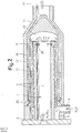
- FIG. 2 The exemplary embodiment in FIG. 2 is largely the same as that in FIG. 1, and corresponding parts therefore have the same reference numerals.
- This embodiment differs from that of FIG. 1 only in that the annular space 8 connects radially inwardly directed injection openings 26 to the interior of the reaction chamber 1, while the swirl nozzle arranged in the end wall 11 is missing.
- the water from the channels 5 is thus radially injected into the reaction chamber at the downstream end thereof.
- the inner wall 32 of the reaction chamber 1 is constructed from a porous sintered metal tube, so that the channels 5 open directly into the reaction chamber via the pores of this porous inner wall, that is to say the pores act as injection openings for that in the channels 5 heated water.
- An outlet occurs essentially in the part located downstream, in which the water is partially converted into vapor form by increasing the temperature. Due to the emerging steam-water mixture, a cooling film is formed in the reaction chamber along the wall due to the flow velocity, which protects this wall against excessive heating, absorbs heat and completely evaporates.
- the evaporator chamber connects downstream to the reaction chamber.
- the solution according to the invention provides that, in accordance with the exemplary embodiments in FIGS. 1 and 2, the reaction chamber is surrounded by coaxial evaporator chambers.
- the outlet 17 is closed by a spring-loaded poppet valve 40, which under the action of a compression spring 41 is pressed against an outwardly widening valve seat 42.
- the outlet 17 is closed by the poppet valve 40.
- the poppet valve 40 can be lifted against the action of the compression spring 41 from the valve seat 42, so that water vapor can pass from the outlet 17 past the poppet valve 40 to laterally arranged outlet openings 43 which lead to a consumer, for example the sterilization system of a canned packaging system.
- the outlet 17 is likewise closed by means of a poppet valve 40, but does not close the outlet in a spring-loaded manner, but rather can be moved between the closed position and the open position by means of an actuating device.
- the actuating device can be, for example, a magnetic coil 44, which is reversed by a controller 45 between the open position and the closed position.
- a pressure sensor 46 which is connected to the controller 45 via a control line 47, is arranged in the area of the outlet 17 arranged upstream of the valve.
- the controller 45 sends a valve-opening signal to the solenoid 44, which then either keeps the valve open for a certain period of time or closes the valve when the pressure detected by the pressure sensor 46 is below a certain threshold has fallen.
- steam pulses can be generated intermittently, the pulse sequence and pulse length of which can be controlled by the steam generation rate, which in turn depends on the supply of the hydrogen-oxygen-fuel mixture and the quantity of the injected water.
Description
Die Erfindung betrifft einen Dampferzeuger mit den im Oberbegriff des Patentanspruches 1 angegebenen Merkmalen.The invention relates to a steam generator with the features specified in the preamble of
Aus der GB-A-469 738 ist ein Dampferzeuger bekannt, bei dem Wasser unter Druck in den Verbrennungsraum eingespritzt wird.From GB-A-469 738 a steam generator is known in which water is injected under pressure into the combustion chamber.
Es ist auch ein Dampferzeuger bekannt, bei dem das zugeführte Wasser praktisch unter demselben Druck zugeführt wird, der im Reaktionsraum herrscht (DE-A-2 426 872). Dabei wird das Kühlwasser in einer äußeren, den Ringraum umgebenden Schale erwärmt und verdampft und strömt als reiner Wasserdampf durch eine innere, unmittelbar an den Ringraum angrenzende Schale zu den Einspritzöffnungen. Eine effektive Kühlung des Ringraums läßt sich dabei nicht erreichen, da unmittelbar angrenzend an den Ringraum dieser nur von dampfförmigem Wasser umströmt wird. Um eine Überhitzung der Brennkammerwand zu vermeiden, wird daher bei diesem bekannten Dampferzeuger vorgeschlagen, mehrere Brennkammern abwechselnd in Betrieb zu nehmen. Dies ist eine aufwendige Lösung, außerdem können die Brennkammern dabei nicht im Gleichgewicht betrieben werden.A steam generator is also known, in which the water supplied is fed in practically under the same pressure that prevails in the reaction space (DE-A-2 426 872). The cooling water is heated and evaporated in an outer shell surrounding the annular space and flows as pure water vapor through an inner shell directly adjacent to the annular space to the injection openings. Effective cooling of the annular space cannot be achieved, since only vaporous water flows directly adjacent to the annular space. In order to avoid overheating of the combustion chamber wall, it is therefore proposed in this known steam generator to start up several combustion chambers alternately. This is a complex solution, and the combustion chambers cannot be operated in equilibrium.
Der beschriebene Dampferzeuger ist ein Großgerät, mit dem unter sehr hohen Temperaturen stehender Dampf mit hohem Druck erzeugt wird. Er ist nur für diesen Einsatzzweck geeignet, kann jedoch nicht für Dampferzeuger kleiner Abmessungen verwendet werden, beispielsweise für Dampferzeuger in der Größenordnung einer Länge von 15 cm und für geringe Drücke in der Größenordnung von 2 bis 15 Bar. Außerdem bietet die dampfförmige Umströmung des Reaktionsraumes keine ausreichende Kühlung für die Wände des Reaktionsraumes.The steam generator described is a large device with which steam at very high temperatures is generated at high pressure. It is only suitable for this purpose, but cannot be used for steam generators of small dimensions, for example for steam generators in the order of 15 cm in length and for low pressures in the order of 2 to 15 bar. In addition, the vaporous flow around the reaction chamber does not offer any adequate cooling for the walls of the reaction space.
Ausgehend von diesem bekannten Dampferzeuger liegt der Erfindung die Aufgabe zugrunde, einerseits eine möglichst kurze Bauform eines Verdampfers zu erhalten und andererseits dafür zu sorgen, daß ein Dampferzeuger geschaffen wird, der möglichst reinen Wasserdampf erzeugt, wobei in dem Wasserdampf weder unverbrannte Reaktionspartner noch flüssige Wasserteilchen enthalten sein sollen.Proceeding from this known steam generator, the object of the invention is, on the one hand, to obtain the shortest possible design of an evaporator and, on the other hand, to ensure that a steam generator is created which generates the purest possible water vapor, the water vapor containing neither unburned reactants nor liquid water particles should be.
Diese Aufgabe wird bei einem Dampferzeuger der eingangs beschriebenen Art erfindungsgemäß dadurch gelöst, daß die Verdampferkammer einen unmittelbar mit der Reaktionskammer verbundenen inneren Ringraum und einen dazu nachgeschalteten, ebenfalls koaxial zur Reaktionskammer angeordneten, äußeren Ringraum umfaßt und daß zwischen den beiden Ringräumen die Strömungsverengung angeordnet ist. Durch diese Maßnahme wird einerseits eine effektive Kühlung der Reaktorwand aufgrund des flüssigen Wassers erreicht, andererseits führt die Strömungsverengung zwischen den beiden Ringräumen zu einer Erhöhung der Strömungsgeschwindigkeit des Wasser-Dampf-Gemisches. Eine solche Erhöhung der Strömungsgeschwindigkeit, die im übrigen bereits im Bereich der Einspritzöffnungen selbst stattfindet, führt zu einer erhöhten Relativgeschwindigkeit zwischen Wasserdampf einerseits und den flüssigen Wassertröpfchen andererseits. Diese unterschiedliche Strömungsgeschwindigkeit fördert den Verdampfungsvorgang der Wassertröpfchen, so daß durch diese Drosselung im Bereich der Einspritzöffnungen und durch eine anschließende Drosselung ebenfalls die Homogenisierung des Dampfes gefördert wird. Die Verengung wirkt außerdem als Drossel, so daß durch die beim Durchströmen der Drossel auftretende Entspannung, die beispielsweise zu einer Halbierung des Wasserdampfdruckes führen kann, eine spontane Verdampfung etwa noch flüssig vorliegender Parttikel erfolgt.This object is achieved according to the invention in a steam generator of the type described in the introduction in that the evaporator chamber comprises an inner annular space which is directly connected to the reaction chamber and an outer annular space which is connected downstream thereof and is also arranged coaxially to the reaction chamber and that the flow restriction is arranged between the two annular spaces. This measure on the one hand achieves effective cooling of the reactor wall due to the liquid water, and on the other hand the flow restriction between the two annular spaces leads to an increase in the flow rate of the water-steam mixture. Such an increase in the flow rate, which otherwise already takes place in the area of the injection openings themselves, leads to an increased relative speed between water vapor on the one hand and the liquid water droplets on the other. This different flow rate promotes the evaporation process of the water droplets, so that this throttling in the area of the injection openings and a subsequent throttling also promote the homogenization of the steam. The constriction also acts as a throttle, so that the relaxation that occurs when flowing through the throttle, which can lead, for example, to a halving of the water vapor pressure, results in spontaneous evaporation of particles that are still liquid.
Bei Brennern für fossile Brennstoffe, bei denen in die heissen Brenngase Wasser zum Zwecke der Verdampfung eingespritzt wird, ist es zwar bereits bekannt, den Einspritzraum zu verengen und daran eine sich erweiternde Kammer anzuschließen (FR-A-662 772), jedoch ist diese bekannte Vorrichtung nicht mit einem Wasserstoff-Sauerstoffbrenner vergleichbar, bei dem als Brenngas ebenfalls Wasserdampf entsteht. Bei der bekannten Vorrichtung, die beispielsweise mit Gas oder Öl geheizt wird, entstehen vielmehr Mischungen von Wasserdampf mit den Rauchgasen. Darüber hinaus erfolgt die Verdampfung bei der bekannten Vorrichtung in einem sich verengenden Reaktionsraum und nicht in der sich daran anschließenden vergrößerten Kammer.In the case of burners for fossil fuels, in which water is injected into the hot fuel gases for the purpose of evaporation, it is already known to narrow the injection space and to connect an expanding chamber to it (FR-A-662 772), but this is known Device not comparable to a hydrogen-oxygen burner, in which water vapor is also generated as fuel gas. In the known device, which is heated with gas or oil, for example, mixtures of water vapor with the flue gases are created. In addition, the evaporation takes place in the known device in a narrowing reaction chamber and not in the adjoining enlarged chamber.
Günstig ist es, wenn die Kühlkanäle die Reaktionskammer wendelförmig umgeben, dadurch ergibt sich eine besonders lange Erwärmzeit für das Kühlwasser in der Wand der Reaktionskammer.It is expedient if the cooling channels surround the reaction chamber in a helical shape, which results in a particularly long heating time for the cooling water in the wall of the reaction chamber.
Günstig ist es weiterhin, wenn die Einspritzöffnungen entgegen der Strömungsrichtung der Reaktionsgase in der Reaktionskammer gerichtet sind.It is also expedient if the injection openings are directed in the reaction chamber counter to the direction of flow of the reaction gases.
Bei einem bevorzugten Ausführungsbeispiel ist vorgesehen, daß die Einspritzöffnungen Teil einer Dralldüse sind, in die die Kühlkanäle so exzentrisch einmünden, daß das Dampf-Wasser-Gemisch vor dem Einspritzen in die Reaktionskammer in Rotation versetzt wird.In a preferred embodiment it is provided that the injection openings are part of a swirl nozzle, into which the cooling channels open so eccentrically that the steam-water mixture is set in rotation before being injected into the reaction chamber.
Bei einem abgewandelten Ausführungsbeispiel kann vorgesehen sein, daß die Einspritzöffnungen und zumindest zum Teil die Kühlkanäle durch die Poren eines porösen die Reaktionskammer umgebenden Einspritzkörpers gebildet werden, beispielsweise durch ein Sintermetallrohr.In a modified exemplary embodiment it can be provided that the injection openings and at least partly the cooling channels are formed by the pores of a porous injection body surrounding the reaction chamber, for example by a sintered metal tube.
In allen Fällen ist es vorteilhaft, wenn der Verdampferraum über einen Auslaß mit verringertem Strömungsquerschnitt an einen Dampfverbraucher anschließbar ist. Der Querschnitt kann dabei in der Form ausgebildet sein, daß der Druck des austretenden Dampfes den jeweiligen Erfordernissen angepaßt ist.In all cases it is advantageous if the evaporator chamber can be connected to a steam consumer via an outlet with a reduced flow cross section. The cross section can be designed in such a way that the pressure of the emerging steam is adapted to the respective requirements.
Der beschriebene Dampferzeuger kann besonders vorteilhaft zur Erzeugung von Wasserdampfimpulsen verwendet werden, wie sie beispielsweise bei der Sterilisation des inhalts von Konservendosen verwendet werden. Es kann dazu vorgesehen sein, daß der Verdampferraum über einen intermittierend verschließbaren Auslaß an einen Dampfverbraucher anschließbar ist, beispielsweise eine Sterilisierstation in einer Konservenverpackungsanlage.The steam generator described can be used particularly advantageously for generating water vapor pulses, such as those used for sterilizing the contents of cans. It can do this be seen that the evaporator room can be connected to a steam consumer via an intermittently closable outlet, for example a sterilizing station in a canned packaging system.
Dabei ist es vorteilhaft, wenn der Auslaß mittels eines federbelasteten Auslaßventils verschlossen ist, das bei Überschreiten eines bestimmten Drukkes des Wasserdampfes in dem Verdampferraum entgegen der Wirkung einer Feder in die Offenstellung verschiebbar ist. Allein durch die Steuerung der Wasserstoff-Sauerstoff-Zufuhr einerseits und der Menge der Wassereinspritzung andererseits läßt sich die erzeugte Wasserdampfmenge steuern, und dadurch wird die Impulsfolge des federbelasteten Auslaßventils gesteuert, da sich bei verstärkter Wasserdampferzeugung der zur Öffnung des federbelasteten Auslaßventils notwendige Druck schneller aufbaut.It is advantageous if the outlet is closed by means of a spring-loaded outlet valve which, when a certain pressure of the water vapor in the evaporator chamber is exceeded, can be moved into the open position against the action of a spring. Simply by controlling the hydrogen-oxygen supply on the one hand and the amount of water injection on the other hand, the amount of water vapor generated can be controlled, and thereby the pulse sequence of the spring-loaded exhaust valve is controlled, since the pressure required to open the spring-loaded exhaust valve builds up faster with increased steam generation.
Bei einer abgewandelten Ausführungsform ist vorgesehen, daß der Auslaß mittels eines mit einem Stellantrieb betätigbaren Auslaßventil versehen ist und daß im Verdampferraum ein Drucksensor angeordnet ist, der beim Überschreiten eines bestimmten Druckes in dem Verdampferraum einer Steuerung ein Signal zuführt, welches zur Öffnung des Auslaßventils führt. Das Auslaßventil kann entweder dann für einen bestimmten Zeitraum geöffnet bleiben, oder es wird vorgesehen, daß beim Unterschreiten eines bestimmten Druckwertes im Verdampferraum das Ventil über die Steuerung wieder geschlossen wird.In a modified embodiment it is provided that the outlet is provided by means of an outlet valve which can be actuated by an actuator and that a pressure sensor is arranged in the evaporator chamber which, when a certain pressure in the evaporator chamber is exceeded, supplies a control which leads to the opening of the outlet valve. The outlet valve can then either remain open for a certain period of time, or it is provided that the valve is closed again via the control when the pressure in the evaporator chamber falls below a certain value.
Die nachfolgende Beschreibung der Erfindung dient im Zusammenhang mit der Zeichnung der näheren Erläuterung. Es zeigen:
Figur 1 eine schematische Längsschnittansicht eines ersten Ausführungsbeispieles eines Dampferzeugers mit einer die Reaktionskammer in Form von Ringräumen konzentrisch umgebenden Verdampferkammer und einer Dralldüsengegeneinspritzung für das zugesetzte Wasser;Figur 2 eine Ansichtähnlich Figur 1 eines abgewandelten Ausführungsbeispiels eines Dampferzeugers mit radialer Einspritzung des Wassers in die Reaktionskammer;- Figur 3 eine schematische Längsschnittansicht eines Beispiels eines Dampferzeugers mit einer porösen Reaktionskammerinnenwand;
Figur 4 eine Längsschnittansicht des Auslaßbereichs eines Dampferzeugers mit einem federbelasteten Auslaßventil undFigur 5 eine Ansichtähnlich Figur 4 eines magnetbetätigten Auslaßventils mit Drucksensorsteuerung.
- Figure 1 is a schematic longitudinal sectional view of a first embodiment of a steam generator with an evaporator chamber concentrically surrounding the reaction chamber in the form of annular spaces and a swirl nozzle counter-injection for the added water;
- Figure 2 is a view similar to Figure 1 of a modified embodiment of a steam generator with radial injection of the water into the reaction chamber;
- FIG. 3 shows a schematic longitudinal sectional view of an example of a steam generator with a porous reaction chamber inner wall;
- Figure 4 is a longitudinal sectional view of the outlet area of a steam generator with a spring-loaded outlet valve and
- Figure 5 is a view similar to Figure 4 of a solenoid operated exhaust valve with pressure sensor control.
Der in Figur 1 dargestellte Dampferzeuger umfaßt eine zylindrische, langgestreckte Reaktionskammer 1 mit einer abgeschlossenen Stirnwand 2, die eine zentrale Einlaßöffnung 3 aufweist. Diese steht mit einem in der Zeichnung nicht dargestellten Einblas- und Zündelement in Verbindung, welches ein zündfähiges Wasserstoff-Sauerstoff-Gemisch herstellt und in die Reaktionskammer 1 einleitet. Dieses zündfähige Gasgemisch wird in der in der Zeichnung nicht dargestellten Zündeinrichtung gezündet, so daß es im Inneren der Reaktionskammer 1 unter Bildung von hocherhitztem Wasserdampf reagiert. Das Reaktionsprodukt ist bei Verwendung einer stöchiometrischen Gasgmischung reiner Wasser- dampf.The steam generator shown in FIG. 1 comprises a cylindrical,
In der Wand 4 der Reaktionskammer 1 verlaufen achsparallele Kanäle 5 mit geringem Querschnitt, die mit einem am stromaufwärtigen Ende der Reaktionskammer 1 angeordneten, mit einem Wassereinlaß 6 versehenen Ringraum 7 in Verbindung stehen. Diese Wasserkanäle können über den Umfang verteilte, diskrete Kanäle sein, die Kanäle können auch durch einen die Reaktionskammer umgebenden Ringspalt gebildet sein, wobei dann die Innenwand und die Außenwand. der Reaktionskammer über die in der Zeichnungnicht dargestellten Stege miteinander verbunden sind. Speziell in dem in Figur 1 dargestellten Ausführungsbeispiel umgeben die Kanäle 5 die Innenwand der Reaktionskammer 1 wendelförmig. Zu diesem Zweck kann die Außenwand der Reaktionskammer ein Gewinde tragen, über welches eine Hülse 21 geschoben ist, die dicht an den einzelnen Gewindegängen anliegt und dadurch einen wendelförmigen Kanal ausbildet.In the
Die Kanäle 5 münden am stromabwärts gelegenen Ende der Reaktionskammer in einen weiteren Ringraum 8, aus dem ein schräg zur Reaktionskammerlängsachse verlaufender Kanal 9 austritt, der in eine Dralldüse 10 in der verschlossenen Stirnwand 11 der Reaktionskammer 1 eintritt.-Die Dralldüse ist dabei konzentrisch zur Reaktionskammer 1 angeordnet und weist einen rotationssymmetrischen Hohlraum 12 auf, in den der Kanal 9 derart exzentrisch eintritt, daß durch ihn in den Hohlraum strömendes Medium um die Längsachse der Dralldüse in Drehung versetzt wird. Auf dieser Längsachse ist der Hohlraum 12 über eine zentral angeordnete Einspritz öffnung mit dem Inneren der Reaktionskammer 1 verbunden, so daß das aus dem Hohlraum 12 austretende Wasser entgegen der Gasströmungsrichtung in der Reaktionskammer in Form eines rotationssymmetrischen Schleiers 14 in die Reaktionskammer eingespritzt wird, wobei sich das eingespritzte Wasser an die Innenwand der Reaktionskammer anlegt und diese zusätzlich kühlt.The
Die Reaktionskammer 1 wird von einem sich über deren gesamte Länge erstreckenden Ringraum 22 umfangen, der koaxial zur Reaktionskammer 1 angeordnet ist. Er steht über Radialkanäle 23 mit dem stromabwärts gelegenen, von der Stirnwand 11 verschlossenen Ende der Reaktionskammer 1 in Verbindung.The
Der Ringraum 22 ist seinerseits von einem weiteren Ringraum 24 umgeben, der ebenfalls koaxial zur Reaktionskammer 1 angeordnet ist. Am stromaufwärts gelegenen Ende des Dampferzeugers sind der innere Ringraum 22 und der äußere Ringraum 24 über Drosselkanäle 25 miteinander verbunden, die einen gegenüber den Ringräumen kleinen Strömungsquerschnitt aufweisen.The
Der äußere Ringraum 24 verjüngt sich im Bereich der konisch ausgebildeten Stirnwand 11 ebenfalls konisch und mündet in den Auslaß 17 ein, an den ein geeigneter Verbraucher angeschlossen werden kann.The outer
Der innere Ringraum und der äußere Ringraum bilden dabei eine Verdampferkammer, diese ist also in zwei Schalen koaxial um die Reaktionskammer 1 herumgelegt, so daß insgesamt eine sehr geringe Baulänge des Dampferzeugers möglich wird. Trotzdem kann in den beiden als Verdampferkammer wirkenden Ringräumen eine vollständige und gleichmäßige Verdampfung des flüssigen Wassers und eine Homogenisierung des Dampfes erfolgen, wobei die Drosselikanäle 25 in der oben bereits beschriebenen Weise durch Erzeugung unterschiedlicher Strömungsgeschwindigkeiten zu dieser Homogenisierung beitragen. Das in den Kanälen 5 geführte Wasser kann wegen des gegenüber dem Verdampferraum erhöhten Druckes in der Regel auch eine Temperatur annehmen, die über der des zu erzeugenden Dampfes liegt. In diesem Ausführungsbeispiel wird deshalb vom überhitzten Waser der Kanäle 5 über die Hülse 21 zusätzlich Wärme an das im Ringraum 22 strömende Wasser-DampfGemisch übertragen und somit die Verdampfung des verbliebenen Wasseranteils gefördert.The inner annulus and the outer annulus form an evaporator chamber, which is thus coaxially placed around the
Im Betrieb des Dampferzeugers wird ein entzündbares, vorzugsweise stöchiometrisches Gasgemisch aus Wasserstoff und Sauerstoff in der Reaktionskammer zu Wasserdampf verbrannt. Durch die Kanäle 5 geleitetes Wasser kühlt dabei die Wand der Reaktionskammer ab und heizt sich selbst dabei stark auf. Der Durchsatz des Kühlwassers und der Druck in den zu den Einspritzöffnungen führenden Zuleitungskanälen werden so gewählt, daß zumindest ein Teil des zugeführten Wassers im flüssigen Zustand verbleibt, wobei jedoch durch die Wärmezufuhr aus der Reaktionskammer so viel Energie in das Wasser zugeführt ist, daß es bei der Entspannung im Bereich der Einspritzdüsen spontan in den Dampfzustand übergeht, ohne daß dazu weitere Energiezufuhr aus den heißen Brenngasen notwendig wäre. Vorzugsweise erhält man also in der Nähe der Einspritzöffnungen ein Zweiphasengemisch, welches beim Austritt in die Reaktionskammer spontan in den Dampfzustand übergeht.When the steam generator is in operation, an inflammable, preferably stoichiometric, gas mixture of hydrogen and oxygen is burned to water vapor in the reaction chamber. Water passed through the
Das Zweiphasengemisch wird im Gegenstrom in die heißen Reaktionsgase in der Reaktionskammer eingespritzt, wobei durch die Drosselung im Bereich der Einspritzöffnungen und die anschließende Entspannung in der Reaktionskammer große Geschwindigkeitsdifferenzen zwischen dampfförmig aus den Einspritzöffnungen austretendem Wasser und flüssigem Wasser auftreten. Diese Strömungsdifferenzen fördern die Verdampfung des flüssigen Wassers. Dieser Effekt wird auch durch die heißen Reaktionsgase und die Gegenstromeinspritzung zusätzlich gefördert.The two-phase mixture is injected countercurrently into the hot reaction gases in the reaction chamber, the throttling in the area of the injection openings and the subsequent expansion in the reaction chamber causing large speed differences between water and liquid water emerging in vapor form from the injection openings. These flow differences promote the evaporation of the liquid water. This effect is also promoted by the hot reaction gases and countercurrent injection.
Anschließend gelangt die Mischung aus flüssigem und gasförmigem Wasserdampf in den aus den beiden Ringräumen gebildeten Verdampferraum, wobei durch den engen Querschnitt erneut eine Vergrößerung der Geschwindigkeit dieses Zweiphasengemisches eintritt. Durch die Entspannung im Verdampferraum treten wieder große Geschwindigkeitsdifferenzen sowie eine spontane Verdampfung des flüssigen Restanteils auf. Auf diese Weise wird das Wasser bis zum Auslaß des Verdampferraumes vollständig verdampft, so daß homogener Wasserdampf in den anschließenden Verbraucher eintreten kann. Dieser Wasserdamp durchströmt den als Drosselquerschnitt ausgebildeten Auslaß 17 üblicherweise kritisch. Die Temperatur des ausströmenden Dampfes kann je nach Anwendungszweck auch nur geringfügig über der Siedetemperatur liegen, diese Temperatur kann niedriger sein als die Temperatur des aus der Dralldüse in die Reaktionskammer eingespritzten Zweiphasengemisches.The mixture of liquid and gaseous water vapor then passes into the evaporator chamber formed from the two annular spaces, the speed of this two-phase mixture increasing again due to the narrow cross section. Due to the expansion in the evaporator chamber, large speed differences and spontaneous evaporation of the remaining liquid fraction occur again. In this way, the water is completely evaporated up to the outlet of the evaporator chamber, so that homogeneous water vapor can enter the subsequent consumer. This water vapor usually flows critically through the
Der beschriebene Dampferzeuger kann sehr geringe bauliche Abmessungen haben und ist insbesondere auch für die verzögerungsfreie Bereitstellung von Heißdampf wählbaren Zustands auf oder oberhalb der Siedelinie in einem niedrigen Leistungsbereich geeignet, beispielsweise bei einer Leistung von 1 bis 500 kW thermisch. Mit diesem Dampferzeuger ist sowohl ein kontinuierlicher als auch ein intermittierender Betrieb bei konstantem Zustand aber auch bei veränderbarem Dampfzustand und variabler Leistung möglich.The steam generator described can have very small structural dimensions and is also particularly suitable for the instantaneous provision of hot steam of selectable state on or above the boiling line in a low power range, for example with a power of 1 to 500 kW thermally. With this steam generator, continuous as well as intermittent operation is possible with constant condition but also with changeable steam condition and variable output.
Das Ausführungsbeispiel der Figur 2 gleicht dem der Figur 1 weitgehend, einander entsprechende Teile tragen daher dieselben Bezugszeichen. Diese Ausführungsform unterscheidet sich von der der Figur 1 lediglich dadurch, daß den Ringraum 8 radial nach innen gerichtete Einspritzöffnungen 26 mit dem Innenraum der Reaktionskammer 1 verbinden, während die in der Stirnwand 11 angeordnete Dralldüse fehlt. Bei diesem Ausführungsbeispiel wird das Wasser aus den Kanälen 5 somit am stromabwärtigen Ende der Reaktionskammer radial in diese eingespritzt.The exemplary embodiment in FIG. 2 is largely the same as that in FIG. 1, and corresponding parts therefore have the same reference numerals. This embodiment differs from that of FIG. 1 only in that the
Bei dem in Figur 3 dargestellten Beispiel ist die Innenwand 32 der Reaktionskammer 1 aus einem porösen Sintermetallrohr aufgebaut, so daß die Kanäle 5 über die Poren dieser porösen Innenwand unmittelbar in die Reaktionskammer münden, das heißt die Poren wirken als Einspritzöffnungen für das in den Kanälen 5 erhitzte Wasser. Dabei erfolgt ein Austritt im wesentlichen in dem stomabwärts gelegenen Teil, in dem das Wasser durch Temperaturerhöhung teilweise in Dampfform umgewandelt ist. Durch das austretende Dampf-Wasser-Gemisch wird infolge der Strömungsgeschwindigkeit im Reaktionsraum entlang dessen Wand ein Kühlfilm gebildet, der diese Wand vor zu hoher Erwärmung schützt, hierbei Wärme aufnimmt und vollständig verdampft.In the example shown in FIG. 3, the
Bei diesem Beispiel schließt sich der Verdampferraum stromabwärts an die Reaktionskammer an. Die erfindungsgemäß Lösung sieht dagegen vor, daß, entsprechend den Ausführungsbeispielen der Figuren 1 und 2, die Reaktionskammervon koaxialen Verdampferkammern umgeben wird.In this example, the evaporator chamber connects downstream to the reaction chamber. In contrast, the solution according to the invention provides that, in accordance with the exemplary embodiments in FIGS. 1 and 2, the reaction chamber is surrounded by coaxial evaporator chambers.
Bei dem in Figur 4 dargestellten Ausführungsbeispiel ist der Auslaß 17 durch ein federbelastetes Tellerventil 40 verschlossen, welches unter der Wirkung einer Druckfeder 41 gegen einen sich nach außen hinerweiternden Ventilsitz 42 gedrückt wird. In der Darstellung der Figur 4 ist der Auslaß 17 durch das Tellerventil 40 verschlossen. Das Tellerventil 40 kann gegen die Wirkung der Druckfeder 41 vom Ventilsitz 42 abgehoben werden, so daß Wasserdampf aus dem Auslaß 17 am Tellerventil 40 vorbei zu seitlich angeordneten Auslaßöffnungen 43 gelangen kann, die zu einem Verbraucher führen, beispielsweise der Sterilisationsanlage einer Konservenverpackanlage.In the embodiment shown in Figure 4, the
Bei dem Ausführungsbeispiel der Figur 5 ist der Auslaß 17 ebenfalls mittels eines Tellerventils 40 verschlossen, daß jedoch nicht federbelastet den Auslaß verschließt, sondern mittels einer Betätigungsvorrichtung zwischen der Schließstellung und der Offenstellung verschoben werden kann. Die Betätigungsvorrichtung kann beispielsweise eine Magnetspule 44 sein, die von einer Steuerung 45 zwischen der Offenstellung und der Schließstellung umgesteuert wird. In dem stromaufwärts des Ventils angeordneten 8ereich des Auslasses 17 ist ein Drucksensor 46 angeordnet, der über eine Steuerleitung 47 mit der Steuerung 45 in Verbindung steht. Überschreitet der vom Drucksensor 46 festgestellte Druck einen bestimmten Wert, gibt die Steuerung 45 ein das Ventil öffnendes Signal an die Magnetspule 44, die dann entweder für einen bestimmten Zeitraum das Ventil offen hält oder das Ventil dann schließt, wenn der vom Drucksensor 46 festgestellte Druck unter einen bestimmten Schwellwert gefallen ist.In the exemplary embodiment in FIG. 5, the
Sowohl mit der Ausführung der Figur 4 als auch mit der Ausführung der Figur 6 können intermittierend Dampfimpulse erzeugt werden, deren Impulsfolge und Impulslänge durch die Wasserdampferzeugungsrate gesteuert werden können, die ihrerseits wieder abhängt von der Zufuhr des Wasserstoff-Sauerstoff-Brennstoff-Gemisches und der Menge des eingespritzten Wassers.Both with the embodiment of FIG. 4 and with the embodiment of FIG. 6, steam pulses can be generated intermittently, the pulse sequence and pulse length of which can be controlled by the steam generation rate, which in turn depends on the supply of the hydrogen-oxygen-fuel mixture and the quantity of the injected water.
Claims (9)
Applications Claiming Priority (2)
| Application Number | Priority Date | Filing Date | Title |
|---|---|---|---|
| DE3512947 | 1985-04-11 | ||
| DE19853512947 DE3512947A1 (en) | 1985-04-11 | 1985-04-11 | METHOD FOR PRODUCING WATER VAPOR AND STEAM GENERATOR FOR CARRYING OUT THIS METHOD |
Publications (3)
| Publication Number | Publication Date |
|---|---|
| EP0197555A2 EP0197555A2 (en) | 1986-10-15 |
| EP0197555A3 EP0197555A3 (en) | 1987-09-30 |
| EP0197555B1 true EP0197555B1 (en) | 1990-08-01 |
Family
ID=6267705
Family Applications (1)
| Application Number | Title | Priority Date | Filing Date |
|---|---|---|---|
| EP86104859A Expired - Lifetime EP0197555B1 (en) | 1985-04-11 | 1986-04-09 | Steam generator |
Country Status (2)
| Country | Link |
|---|---|
| EP (1) | EP0197555B1 (en) |
| DE (2) | DE3512947A1 (en) |
Cited By (3)
| Publication number | Priority date | Publication date | Assignee | Title |
|---|---|---|---|---|
| US6389814B2 (en) | 1995-06-07 | 2002-05-21 | Clean Energy Systems, Inc. | Hydrocarbon combustion power generation system with CO2 sequestration |
| US6910335B2 (en) | 2000-05-12 | 2005-06-28 | Clean Energy Systems, Inc. | Semi-closed Brayton cycle gas turbine power systems |
| US7882692B2 (en) | 2004-04-16 | 2011-02-08 | Clean Energy Systems, Inc. | Zero emissions closed rankine cycle power system |
Families Citing this family (6)
| Publication number | Priority date | Publication date | Assignee | Title |
|---|---|---|---|---|
| DE4012431C1 (en) * | 1990-04-19 | 1991-08-01 | Balcke-Duerr Ag, 4030 Ratingen, De | |
| US6247316B1 (en) | 2000-03-22 | 2001-06-19 | Clean Energy Systems, Inc. | Clean air engines for transportation and other power applications |
| DE20221983U1 (en) | 2002-09-17 | 2010-03-04 | Alstom Technology Ltd. | Steam generator for generating water vapor, in particular ultrapure water vapor |
| DE102008015915A1 (en) | 2008-03-27 | 2009-10-15 | Giese, Michael, Dr.-Ing. | engine |
| DE202008018190U1 (en) | 2008-03-27 | 2011-12-15 | Michael Giese | engine |
| DE102012219755A1 (en) * | 2012-10-29 | 2014-04-30 | Thyssenkrupp Marine Systems Gmbh | Method for generating water vapor |
Family Cites Families (10)
| Publication number | Priority date | Publication date | Assignee | Title |
|---|---|---|---|---|
| BE397331A (en) * | ||||
| FR613951A (en) * | 1925-08-10 | 1926-12-03 | Improvement in rapid vaporization boilers | |
| FR662772A (en) * | 1928-10-22 | 1929-08-12 | Steam generator | |
| GB333922A (en) * | 1929-04-23 | 1930-08-25 | George Rolfe Stow | Improvements in or relating to steam power plants |
| GB463738A (en) * | 1935-10-22 | 1937-04-06 | Rudolf Arnold Erren | Improvements relating to direct contact steam generators |
| SE7407063L (en) * | 1973-06-04 | 1974-12-05 | Gcoe Corp | |
| US4211071A (en) * | 1978-05-19 | 1980-07-08 | Vapor Energy, Inc. | Vapor generators |
| DE2933932C2 (en) * | 1979-08-22 | 1982-12-09 | Deutsche Forschungs- und Versuchsanstalt für Luft- und Raumfahrt e.V., 5300 Bonn | Steam generator |
| US4390062A (en) * | 1981-01-07 | 1983-06-28 | The United States Of America As Represented By The United States Department Of Energy | Downhole steam generator using low pressure fuel and air supply |
| US4475883A (en) * | 1982-03-04 | 1984-10-09 | Phillips Petroleum Company | Pressure control for steam generator |
-
1985
- 1985-04-11 DE DE19853512947 patent/DE3512947A1/en not_active Withdrawn
-
1986
- 1986-04-09 EP EP86104859A patent/EP0197555B1/en not_active Expired - Lifetime
- 1986-04-09 DE DE8686104859T patent/DE3673046D1/en not_active Expired - Fee Related
Cited By (3)
| Publication number | Priority date | Publication date | Assignee | Title |
|---|---|---|---|---|
| US6389814B2 (en) | 1995-06-07 | 2002-05-21 | Clean Energy Systems, Inc. | Hydrocarbon combustion power generation system with CO2 sequestration |
| US6910335B2 (en) | 2000-05-12 | 2005-06-28 | Clean Energy Systems, Inc. | Semi-closed Brayton cycle gas turbine power systems |
| US7882692B2 (en) | 2004-04-16 | 2011-02-08 | Clean Energy Systems, Inc. | Zero emissions closed rankine cycle power system |
Also Published As
| Publication number | Publication date |
|---|---|
| DE3512947A1 (en) | 1986-10-16 |
| EP0197555A2 (en) | 1986-10-15 |
| EP0197555A3 (en) | 1987-09-30 |
| DE3673046D1 (en) | 1990-09-06 |
Similar Documents
| Publication | Publication Date | Title |
|---|---|---|
| EP0685683B1 (en) | Industrial burner with low NOx emissions and method of operating the same | |
| EP1995515B1 (en) | Supported FLOX operation and burner therefor | |
| DE2530653A1 (en) | METHOD AND DEVICE FOR GENERATING HYDROGEN-RICH GAS | |
| DE3036841C2 (en) | Evaporation burners for liquid fuel, in particular kerosene | |
| WO1981001186A1 (en) | Method and device for obtaining microdrops | |
| DE2439872A1 (en) | METHOD AND DEVICE FOR GENERATING HYDROGEN-RICH GAS | |
| EP0197555B1 (en) | Steam generator | |
| WO1998021523A2 (en) | Method and device for the combustion of liquid fuel | |
| WO1986003556A1 (en) | Process and arrangement for burning a liquid or gaseous fuel in a combustion chamber of an internal combustion engine | |
| WO2006024410A1 (en) | Method and device for vaporizing liquid fuels | |
| DE3906854C1 (en) | Burner tube for a blue-burning oil burner | |
| DE2555757C2 (en) | ||
| DE2808874A1 (en) | METHOD AND DEVICE FOR GENERATING A HOT GAS FLOW | |
| DE2210773A1 (en) | Process for burning sulfur and apparatus for carrying out the process | |
| DE2439873A1 (en) | METHOD AND DEVICE FOR GENERATING HYDROGEN-RICH GAS | |
| EP0256451B1 (en) | Process and device for the production of an inflammable gaseous mixture of liquid fuel, water vapour and combustion air | |
| EP0789188A2 (en) | Catalytic burner | |
| EP3460207B1 (en) | Steam generator unit with power to heat function | |
| WO1999060306A1 (en) | Premix burner for liquid fuels | |
| DE10003275A1 (en) | Process for evaporating and / or overheating a fuel | |
| EP0034786B1 (en) | Method of operating a boiler unit and device suited therefor | |
| CH569925A5 (en) | Fuel oil preheater for ensuring complete combustion - has oil tube filled with steel wool connected to burner | |
| DE2821160C2 (en) | ||
| DE1931647A1 (en) | Afterburning exhaust gas from varnish dry - ing cabinets | |
| DE2239317C3 (en) | Liquid fuel incinerator |
Legal Events
| Date | Code | Title | Description |
|---|---|---|---|
| PUAI | Public reference made under article 153(3) epc to a published international application that has entered the european phase |
Free format text: ORIGINAL CODE: 0009012 |
|
| AK | Designated contracting states |
Kind code of ref document: A2 Designated state(s): BE CH DE FR GB IT LI LU NL SE |
|
| PUAL | Search report despatched |
Free format text: ORIGINAL CODE: 0009013 |
|
| AK | Designated contracting states |
Kind code of ref document: A3 Designated state(s): BE CH DE FR GB IT LI LU NL SE |
|
| 17P | Request for examination filed |
Effective date: 19870926 |
|
| 17Q | First examination report despatched |
Effective date: 19880421 |
|
| RAP1 | Party data changed (applicant data changed or rights of an application transferred) |
Owner name: DEUTSCHE FORSCHUNGSANSTALT FUER LUFT- UND RAUMFAHR |
|
| GRAA | (expected) grant |
Free format text: ORIGINAL CODE: 0009210 |
|
| ITF | It: translation for a ep patent filed |
Owner name: BARZANO' E ZANARDO MILANO S.P.A. |
|
| AK | Designated contracting states |
Kind code of ref document: B1 Designated state(s): BE CH DE FR GB IT LI LU NL SE |
|
| REF | Corresponds to: |
Ref document number: 3673046 Country of ref document: DE Date of ref document: 19900906 |
|
| GBT | Gb: translation of ep patent filed (gb section 77(6)(a)/1977) | ||
| ET | Fr: translation filed | ||
| ITTA | It: last paid annual fee | ||
| PLBE | No opposition filed within time limit |
Free format text: ORIGINAL CODE: 0009261 |
|
| STAA | Information on the status of an ep patent application or granted ep patent |
Free format text: STATUS: NO OPPOSITION FILED WITHIN TIME LIMIT |
|
| 26N | No opposition filed | ||
| EPTA | Lu: last paid annual fee | ||
| EAL | Se: european patent in force in sweden |
Ref document number: 86104859.3 |
|
| PGFP | Annual fee paid to national office [announced via postgrant information from national office to epo] |
Ref country code: DE Payment date: 20000325 Year of fee payment: 15 |
|
| PGFP | Annual fee paid to national office [announced via postgrant information from national office to epo] |
Ref country code: GB Payment date: 20000403 Year of fee payment: 15 |
|
| PGFP | Annual fee paid to national office [announced via postgrant information from national office to epo] |
Ref country code: FR Payment date: 20000417 Year of fee payment: 15 |
|
| PGFP | Annual fee paid to national office [announced via postgrant information from national office to epo] |
Ref country code: LU Payment date: 20000421 Year of fee payment: 15 |
|
| PGFP | Annual fee paid to national office [announced via postgrant information from national office to epo] |
Ref country code: SE Payment date: 20000425 Year of fee payment: 15 Ref country code: CH Payment date: 20000425 Year of fee payment: 15 Ref country code: BE Payment date: 20000425 Year of fee payment: 15 |
|
| PGFP | Annual fee paid to national office [announced via postgrant information from national office to epo] |
Ref country code: NL Payment date: 20000427 Year of fee payment: 15 |
|
| PG25 | Lapsed in a contracting state [announced via postgrant information from national office to epo] |
Ref country code: LU Free format text: LAPSE BECAUSE OF NON-PAYMENT OF DUE FEES Effective date: 20010409 Ref country code: GB Free format text: LAPSE BECAUSE OF NON-PAYMENT OF DUE FEES Effective date: 20010409 |
|
| PG25 | Lapsed in a contracting state [announced via postgrant information from national office to epo] |
Ref country code: SE Free format text: LAPSE BECAUSE OF NON-PAYMENT OF DUE FEES Effective date: 20010410 |
|
| PG25 | Lapsed in a contracting state [announced via postgrant information from national office to epo] |
Ref country code: FR Free format text: THE PATENT HAS BEEN ANNULLED BY A DECISION OF A NATIONAL AUTHORITY Effective date: 20010430 Ref country code: BE Free format text: LAPSE BECAUSE OF NON-PAYMENT OF DUE FEES Effective date: 20010430 |
|
| PG25 | Lapsed in a contracting state [announced via postgrant information from national office to epo] |
Ref country code: LI Free format text: LAPSE BECAUSE OF NON-PAYMENT OF DUE FEES Effective date: 20010508 Ref country code: CH Free format text: LAPSE BECAUSE OF NON-PAYMENT OF DUE FEES Effective date: 20010508 |
|
| BERE | Be: lapsed |
Owner name: DEUTSCHE FORSCHUNGSANSTALT FUR LUFT- UND RAUMFAHR Effective date: 20010430 |
|
| PG25 | Lapsed in a contracting state [announced via postgrant information from national office to epo] |
Ref country code: NL Free format text: LAPSE BECAUSE OF NON-PAYMENT OF DUE FEES Effective date: 20011101 |
|
| GBPC | Gb: european patent ceased through non-payment of renewal fee |
Effective date: 20010409 |
|
| EUG | Se: european patent has lapsed |
Ref document number: 86104859.3 |
|
| REG | Reference to a national code |
Ref country code: CH Ref legal event code: PL |
|
| NLV4 | Nl: lapsed or anulled due to non-payment of the annual fee |
Effective date: 20011101 |
|
| PG25 | Lapsed in a contracting state [announced via postgrant information from national office to epo] |
Ref country code: DE Free format text: LAPSE BECAUSE OF NON-PAYMENT OF DUE FEES Effective date: 20020201 |
|
| REG | Reference to a national code |
Ref country code: FR Ref legal event code: ST |
|
| PG25 | Lapsed in a contracting state [announced via postgrant information from national office to epo] |
Ref country code: IT Free format text: LAPSE BECAUSE OF NON-PAYMENT OF DUE FEES;WARNING: LAPSES OF ITALIAN PATENTS WITH EFFECTIVE DATE BEFORE 2007 MAY HAVE OCCURRED AT ANY TIME BEFORE 2007. THE CORRECT EFFECTIVE DATE MAY BE DIFFERENT FROM THE ONE RECORDED. Effective date: 20050409 |