EP0198283A2 - Broad band camouflage screen having a frequency dependent radar attenuation - Google Patents
Broad band camouflage screen having a frequency dependent radar attenuation Download PDFInfo
- Publication number
- EP0198283A2 EP0198283A2 EP86104103A EP86104103A EP0198283A2 EP 0198283 A2 EP0198283 A2 EP 0198283A2 EP 86104103 A EP86104103 A EP 86104103A EP 86104103 A EP86104103 A EP 86104103A EP 0198283 A2 EP0198283 A2 EP 0198283A2
- Authority
- EP
- European Patent Office
- Prior art keywords
- camouflage
- squares
- radar
- material according
- camouflage material
- Prior art date
- Legal status (The legal status is an assumption and is not a legal conclusion. Google has not performed a legal analysis and makes no representation as to the accuracy of the status listed.)
- Withdrawn
Links
Images


Classifications
-
- B—PERFORMING OPERATIONS; TRANSPORTING
- B32—LAYERED PRODUCTS
- B32B—LAYERED PRODUCTS, i.e. PRODUCTS BUILT-UP OF STRATA OF FLAT OR NON-FLAT, e.g. CELLULAR OR HONEYCOMB, FORM
- B32B15/00—Layered products comprising a layer of metal
- B32B15/04—Layered products comprising a layer of metal comprising metal as the main or only constituent of a layer, which is next to another layer of the same or of a different material
- B32B15/08—Layered products comprising a layer of metal comprising metal as the main or only constituent of a layer, which is next to another layer of the same or of a different material of synthetic resin
- B32B15/085—Layered products comprising a layer of metal comprising metal as the main or only constituent of a layer, which is next to another layer of the same or of a different material of synthetic resin comprising polyolefins
-
- B—PERFORMING OPERATIONS; TRANSPORTING
- B32—LAYERED PRODUCTS
- B32B—LAYERED PRODUCTS, i.e. PRODUCTS BUILT-UP OF STRATA OF FLAT OR NON-FLAT, e.g. CELLULAR OR HONEYCOMB, FORM
- B32B27/00—Layered products comprising a layer of synthetic resin
- B32B27/32—Layered products comprising a layer of synthetic resin comprising polyolefins
-
- B—PERFORMING OPERATIONS; TRANSPORTING
- B32—LAYERED PRODUCTS
- B32B—LAYERED PRODUCTS, i.e. PRODUCTS BUILT-UP OF STRATA OF FLAT OR NON-FLAT, e.g. CELLULAR OR HONEYCOMB, FORM
- B32B7/00—Layered products characterised by the relation between layers; Layered products characterised by the relative orientation of features between layers, or by the relative values of a measurable parameter between layers, i.e. products comprising layers having different physical, chemical or physicochemical properties; Layered products characterised by the interconnection of layers
- B32B7/04—Interconnection of layers
- B32B7/12—Interconnection of layers using interposed adhesives or interposed materials with bonding properties
-
- F—MECHANICAL ENGINEERING; LIGHTING; HEATING; WEAPONS; BLASTING
- F41—WEAPONS
- F41H—ARMOUR; ARMOURED TURRETS; ARMOURED OR ARMED VEHICLES; MEANS OF ATTACK OR DEFENCE, e.g. CAMOUFLAGE, IN GENERAL
- F41H3/00—Camouflage, i.e. means or methods for concealment or disguise
-
- B—PERFORMING OPERATIONS; TRANSPORTING
- B32—LAYERED PRODUCTS
- B32B—LAYERED PRODUCTS, i.e. PRODUCTS BUILT-UP OF STRATA OF FLAT OR NON-FLAT, e.g. CELLULAR OR HONEYCOMB, FORM
- B32B2307/00—Properties of the layers or laminate
- B32B2307/40—Properties of the layers or laminate having particular optical properties
- B32B2307/402—Coloured
-
- B—PERFORMING OPERATIONS; TRANSPORTING
- B32—LAYERED PRODUCTS
- B32B—LAYERED PRODUCTS, i.e. PRODUCTS BUILT-UP OF STRATA OF FLAT OR NON-FLAT, e.g. CELLULAR OR HONEYCOMB, FORM
- B32B2307/00—Properties of the layers or laminate
- B32B2307/40—Properties of the layers or laminate having particular optical properties
- B32B2307/412—Transparent
-
- B—PERFORMING OPERATIONS; TRANSPORTING
- B32—LAYERED PRODUCTS
- B32B—LAYERED PRODUCTS, i.e. PRODUCTS BUILT-UP OF STRATA OF FLAT OR NON-FLAT, e.g. CELLULAR OR HONEYCOMB, FORM
- B32B2307/00—Properties of the layers or laminate
- B32B2307/50—Properties of the layers or laminate having particular mechanical properties
- B32B2307/56—Damping, energy absorption
-
- B—PERFORMING OPERATIONS; TRANSPORTING
- B32—LAYERED PRODUCTS
- B32B—LAYERED PRODUCTS, i.e. PRODUCTS BUILT-UP OF STRATA OF FLAT OR NON-FLAT, e.g. CELLULAR OR HONEYCOMB, FORM
- B32B2323/00—Polyalkenes
- B32B2323/04—Polyethylene
-
- B—PERFORMING OPERATIONS; TRANSPORTING
- B32—LAYERED PRODUCTS
- B32B—LAYERED PRODUCTS, i.e. PRODUCTS BUILT-UP OF STRATA OF FLAT OR NON-FLAT, e.g. CELLULAR OR HONEYCOMB, FORM
- B32B2459/00—Nets, e.g. camouflage nets
-
- Y—GENERAL TAGGING OF NEW TECHNOLOGICAL DEVELOPMENTS; GENERAL TAGGING OF CROSS-SECTIONAL TECHNOLOGIES SPANNING OVER SEVERAL SECTIONS OF THE IPC; TECHNICAL SUBJECTS COVERED BY FORMER USPC CROSS-REFERENCE ART COLLECTIONS [XRACs] AND DIGESTS
- Y10—TECHNICAL SUBJECTS COVERED BY FORMER USPC
- Y10S—TECHNICAL SUBJECTS COVERED BY FORMER USPC CROSS-REFERENCE ART COLLECTIONS [XRACs] AND DIGESTS
- Y10S428/00—Stock material or miscellaneous articles
- Y10S428/919—Camouflaged article
-
- Y—GENERAL TAGGING OF NEW TECHNOLOGICAL DEVELOPMENTS; GENERAL TAGGING OF CROSS-SECTIONAL TECHNOLOGIES SPANNING OVER SEVERAL SECTIONS OF THE IPC; TECHNICAL SUBJECTS COVERED BY FORMER USPC CROSS-REFERENCE ART COLLECTIONS [XRACs] AND DIGESTS
- Y10—TECHNICAL SUBJECTS COVERED BY FORMER USPC
- Y10T—TECHNICAL SUBJECTS COVERED BY FORMER US CLASSIFICATION
- Y10T428/00—Stock material or miscellaneous articles
- Y10T428/24—Structurally defined web or sheet [e.g., overall dimension, etc.]
- Y10T428/24273—Structurally defined web or sheet [e.g., overall dimension, etc.] including aperture
- Y10T428/24281—Struck out portion type
-
- Y—GENERAL TAGGING OF NEW TECHNOLOGICAL DEVELOPMENTS; GENERAL TAGGING OF CROSS-SECTIONAL TECHNOLOGIES SPANNING OVER SEVERAL SECTIONS OF THE IPC; TECHNICAL SUBJECTS COVERED BY FORMER USPC CROSS-REFERENCE ART COLLECTIONS [XRACs] AND DIGESTS
- Y10—TECHNICAL SUBJECTS COVERED BY FORMER USPC
- Y10T—TECHNICAL SUBJECTS COVERED BY FORMER US CLASSIFICATION
- Y10T428/00—Stock material or miscellaneous articles
- Y10T428/24—Structurally defined web or sheet [e.g., overall dimension, etc.]
- Y10T428/24273—Structurally defined web or sheet [e.g., overall dimension, etc.] including aperture
- Y10T428/24298—Noncircular aperture [e.g., slit, diamond, rectangular, etc.]
- Y10T428/24314—Slit or elongated
-
- Y—GENERAL TAGGING OF NEW TECHNOLOGICAL DEVELOPMENTS; GENERAL TAGGING OF CROSS-SECTIONAL TECHNOLOGIES SPANNING OVER SEVERAL SECTIONS OF THE IPC; TECHNICAL SUBJECTS COVERED BY FORMER USPC CROSS-REFERENCE ART COLLECTIONS [XRACs] AND DIGESTS
- Y10—TECHNICAL SUBJECTS COVERED BY FORMER USPC
- Y10T—TECHNICAL SUBJECTS COVERED BY FORMER US CLASSIFICATION
- Y10T428/00—Stock material or miscellaneous articles
- Y10T428/24—Structurally defined web or sheet [e.g., overall dimension, etc.]
- Y10T428/24942—Structurally defined web or sheet [e.g., overall dimension, etc.] including components having same physical characteristic in differing degree
- Y10T428/2495—Thickness [relative or absolute]
- Y10T428/24967—Absolute thicknesses specified
- Y10T428/24975—No layer or component greater than 5 mils thick
-
- Y—GENERAL TAGGING OF NEW TECHNOLOGICAL DEVELOPMENTS; GENERAL TAGGING OF CROSS-SECTIONAL TECHNOLOGIES SPANNING OVER SEVERAL SECTIONS OF THE IPC; TECHNICAL SUBJECTS COVERED BY FORMER USPC CROSS-REFERENCE ART COLLECTIONS [XRACs] AND DIGESTS
- Y10—TECHNICAL SUBJECTS COVERED BY FORMER USPC
- Y10T—TECHNICAL SUBJECTS COVERED BY FORMER US CLASSIFICATION
- Y10T428/00—Stock material or miscellaneous articles
- Y10T428/26—Web or sheet containing structurally defined element or component, the element or component having a specified physical dimension
- Y10T428/261—In terms of molecular thickness or light wave length
Definitions
- the invention relates to camouflage materials, particularly a camouflage screen for military targets, effective in the spectral range from visible light to radar waves.
- the present invention is an improvement in the type of camouflage material described in our US-A-4,495,239 and US-A- 4,423,104 which are incorporated herein by reference.
- US-A- 4,495,239 relates to a camouflage material having a broad-band effect in the visible portion of the spectrum, the IR region of the spectrum from 1 to 20 micrometers and the radar region from 3 GHz to 3,000 GHz.
- It comprises a base layer on which is applied a vapor deposited metallic reflecting layer having a surface resistivity of 0.1 to 10 ohms per square and followed by a paint layer containing pigments which have a reflectivity similar, in the visible and near infrared portions of the spectrum, to that of the natural hack- ground, e.g., chlorophyll.
- the paint layer contains a binder which has good transparency in the atmospheric windows II (3-5 ⁇ m) and III (8-14 ⁇ m) of the far infrared portion of the spectrum.
- the basic camouflage material as above described may be further modified as set forth in our US-A- 4,423,104.
- the camouflage material consists of a net to which is attached a garnishing material comprising two or more layers of tne wide-band camouflage material affixed in patches so as to provide spaces therebetween in each layer but arranged so that there is a partial overlap of the patches in one layer on those in another layer thus preventing radiation from penetrating the net. This better imitates the gaps occurring in natural growth, for instance between individual branches.
- the present invention has as its object to provide a camouflage screen which will be effective in the spectral range from visible light to radar waves, and which will have a frequency dependent radar attenuation.
- the camouflage screen garnishing material is characterized, according to the invention, by having the thermal reflecting metallic layer in the form of small squares (or rectangles), so that a radar frequency dependence results as a function of the size of these squares.
- the squares should have a length and/or width which is in the magnitude of the shortest wavelength to be reflected, i.e. they should not be longer and/or larger than approximately 1 cm for a net permeable to 3 cm wavelengths.
- Suitable textile materials which can serve as a base material for the garnishing camouflage material of the present invention include polyvinyl, polyamide, polyetnylene, polypropylene or polyester fibers.
- the prelered fibers are of polyamide coated with plasticized PVC consisting of a blend of 1 part poly(methacrylate and 2 parts of a copolymer consisting of 86% vinyl chloride, 13% vinyl acetate and 17% maleic acid.
- Thermally transparent binders for the camouflage paint layer include cyclic rubber, butyl rubber, polyethylene, polye- thylene ⁇ vinyl acetate copolymers and chlorinated polypropylene.
- Suitable colorants and pigments for the paint layer include chromium oxide green, 4-chloro-2-nitranilide yellow, azine black toner, toludine red toner, titanium dioxide, iron oxide and ultramarine blue
- the reflective metallic layer which is deposited as squares, rectangles or circular disks, preferably squares, (Fig. 1), may be formed from aluninum, copper or zinc, p re- ferably aluminum.
- the radar reflection is 7 dB at 10 GHz (3 cm), 20 dB at 30 GHz and greater than 40 dB at 100 GHz.
- the radar reflection is 3 dB at 1C GHz and 15 dB at 30 GHz and greater than 3C dB at 100 GHz.
- a similar frequency dependence of the radar reflection was measured in nature.
- a support net 21 has trim patches 24 mounted on opposite sides of the support net 21 in two planes 25 and 26.
- the radar screens are formed in a similar manner as shown, in Fig. 3, the long radar waves cnn partially penetrate, the brillance of tile screens decreases and it is not possible to detect them by far reaching radar units with, artificial antennas.
- the detection possibility of the screens by means of radar waves, as used in modern electronic reconnaissance aircrafts, is considerably reduced. (The retro-reflection is considerably smaller.)
- the method of metallizing the whole surface of the garnishing material means that the holes caused by the necessary incisement act as reflective slot antennas and increase the retro-reflection considerably.
- the formation of the small squares interrupts the circulation by the slot antennas and thus reduces the reflection to a tolerable extent.
- the incised contour of the garnishing material grouped similar to the way shown in Fig. 3 provides reflection to all sides at short radar wavelengths, as is shown in nature by bushes, foliage, trees.
- the result is a radar frequency dependent reflection of the camouflaging screens, which corresponds largely to the reflection of the natural background, when the metallic reflective layer of the garnishing material is properly formed into rectangular and square elements.
- These elements can also have other geometric configurations, such as small circular disks. However, the squares show the most satisfactory results.
- the minimum wavelength can be varied by choosing the width (a) of the squares in order to allow 'the transmittance of the radar waves.
- width (a) the only result is that shorter wavelengths cannot be transmitted.
- the transit attenuation of the low-pass filter which is formed by the squares is dependent to a great extent on width (b) or the spaces, which can be varied from 0.5 to approximately 2 mm.
- a thermally transparent color can then be applied on the outside of this film laminate, a measure which provides broad band camouflaging from the visible light to the radar range of the spectrum.
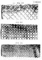
- Fig. 4 shows three different patterns obtained by evaporation of aluminum through different textile lattices onto a textile or non-woven fabric base or a stretched polyethylene film.
- Figs. 5 A-B show the process for manufacturing a laminated, stretched polyethylene film with evaporated patches of aluminum in-between the films.
- a woven nylon textile material of about 60 g/m 2 was coated with about 15 g/m 2 of a plasticized polyvinyl chloride by spraying with a 20% solution in methyl ethyl ketone. After being allowed to dry, the coated textile material was coated on both sides with 20 nanometers of pure aluminum by vapor deposition under vacuum in a pattern as in Fig. 4A by depositing - through a mesh of polyester textile material to provide spaces of 2 mm between 8 mm squares of deposited aluminum- The metallized coating was treated with a 30% solution of chlorinated polypropylene to provide a primer coating of 0.5 g/m 2 . After the primer coating was dried, a camouflage paint was applied.
- the paint contained chromium oxide green as a pigment in a polyethylene-vinyl acetate copolymer binder.
- the pigment and binder had previously been ground together until the average particle size of the pigment was about 1 to 3 microns. Such fine grinding obtains good reflectivity in the visible and near-infrared, with good transparency, thus low absorption/ emissivity in the far infrared.
- a final protective coating of polyolefin resin was applied by spraying from a 20% solution in methyl ethyl ketone. Patches of this material were glued to both sides of a support net made of polyester fibers so that overlapping of the covered areas occurs to prevent direct transmission of reconnaissance radiation through the camouflage material.
- a non-woven polyethylene fabric of about 45 g/m 2 was coated with a polyurethane adhesive and a stretched polyethylene film, previously coated with 30 nanometers of aluminum by vapor deposition in a pattern of squares similar to Fig.4B was applied by rolling. Then the metallized film surface was coated with 1 g/m 2 of a primer consisting of cyclic rubber from a 15% toluene solution. After drying, a camouflage paint was applied in random thickness.
- the paint contained a mixture of chromium oxide green and 4-chloro-2-nitranilide yellow; azine black toner and toludine red toner; and ultramarine 2 toner with a particle size of about 1 to 3 microns applied in a conventional camouflage pattern of olive drab, black and blue areas.
- the binder was a copolymer of polyethylene and vinyl acetate which had been previously ground with the pigment.
- the final protective coating was the same as in Example 1. The material was crimped to form a corrugated surface and applied in patches onto both sides of a nylon support net.
- a textile fabric of woven polyester fibers about 0.5 mm in diameter was coated with a 50 ⁇ m thick layer of polyethylene containing 10% by volume of hair-like filaments of stainless steel having a length of 1.5 to 3 mm which function as a semiconductor.
- a 50 mm thick film of aluminum was vapor deposited in a pattern similar to Fig. 4C under vacuum.
- the aluminum layer was then coated with a 10 / um layer of chlorinated polypropylene containing an optically camouflaging pattern of chromium oxide green, iron oxide and titanium dioxide. Patches of this material were slit to form crescent-shaped slits and attached by gluing to both sides of a nylon support net.
- extruder 1 extrudes a polyethylene film 2. This film is stretched in an angle of 45 degrees to the longitudinal axis to form a stretched polyethylene film 3. Aluminum patches are deposited thereon by evaporation under vacuum to form an aluminum coated stretched polyethylene film 4.
- Fig. 5B shows that a second stretched PE-film 5, which has a stretched direction perpendicular to that of film 4 is laminated with film 4 by the laminator 6,7 so that the aluminum patches are in the middle of the two films and therefore have a very good protection against corrosion and abrasion.
- the thermal transmission of the PE-films is very good so that the thermal reflection of the metallized patches is effective to both sides.
- the upper and lower sides of this laminate are then coated with the well-known thermally translucent paints.
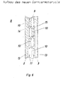
- the base layer is a tissue 8, e. g. synthetic material. It consists of a first sort of small ribbons 9 which are vertically running and a second sort of small ribbons 10 which are crossing respectively two neighbouring small ribbons from the first sort alternatively above and below.
- the two sorts of ribbons are equal in their material and their dimensions and differ only from the direction of their course.
- a thin metal layer 11, e. g. of 10 run, is evaporated on each side of tne visible squares of the tissue and each outside of metal layers is coated by the polyethylene film 2, 3 of about 20 um thickness and containing the outer coloring matter 13.
- the fluid polyethylene adhesive 14 of about 10 g/m 2 that is coating the polyethylene film 2, 3 soakes into the spaces between the small ribbons. Therefore the single squares are definably isolated from each other.
Abstract
Description
- The invention relates to camouflage materials, particularly a camouflage screen for military targets, effective in the spectral range from visible light to radar waves.
- In general, the present invention is an improvement in the type of camouflage material described in our US-A-4,495,239 and US-A- 4,423,104 which are incorporated herein by reference. US-A- 4,495,239 relates to a camouflage material having a broad-band effect in the visible portion of the spectrum, the IR region of the spectrum from 1 to 20 micrometers and the radar region from 3 GHz to 3,000 GHz. It comprises a base layer on which is applied a vapor deposited metallic reflecting layer having a surface resistivity of 0.1 to 10 ohms per square and followed by a paint layer containing pigments which have a reflectivity similar, in the visible and near infrared portions of the spectrum, to that of the natural hack- ground, e.g., chlorophyll. The paint layer contains a binder which has good transparency in the atmospheric windows II (3-5 µm) and III (8-14 µm) of the far infrared portion of the spectrum.
- The basic camouflage material as above described may be further modified as set forth in our US-A- 4,423,104. In this patent the camouflage material consists of a net to which is attached a garnishing material comprising two or more layers of tne wide-band camouflage material affixed in patches so as to provide spaces therebetween in each layer but arranged so that there is a partial overlap of the patches in one layer on those in another layer thus preventing radiation from penetrating the net. This better imitates the gaps occurring in natural growth, for instance between individual branches.
- The present invention has as its object to provide a camouflage screen which will be effective in the spectral range from visible light to radar waves, and which will have a frequency dependent radar attenuation. Accordingly, the camouflage screen garnishing material is characterized, according to the invention, by having the thermal reflecting metallic layer in the form of small squares (or rectangles), so that a radar frequency dependence results as a function of the size of these squares. The squares should have a length and/or width which is in the magnitude of the shortest wavelength to be reflected, i.e. they should not be longer and/or larger than approximately 1 cm for a net permeable to 3 cm wavelengths. In other words, they should be smaller than 1/2 lambda of the longest radar wavelength used for reconnaissance systems and larger than 1/2 lambda of the radar wavelength used for homing missiles and bullets. Wavelengths of 1 cm and less will be reflected by these patterns. Since the squares are very large compared to the IR wavelength, they reflect the IR waves from 4-5.5 µm or 8 to 14 µm very well. This special formation imitates nature in that the long radar waves (3 cm) are not as strongly reflected as the 1 cm or 3 mm radar waves. Millimeter waves are increasingly applied in the military field (e.g. for homing heads, missiles and larger bullets).
-
- Fig. 1 illustrates a pattern of metallic squares in which the length of the squares is approximately 8 mm and the distance between the squares is 1-2 mm.
- Fig. 2 is a graph showing the frequency dependence measured of the attenuation of a plastic foil coated with metallic squares of approximately 8 mm widths and 2 mm spaces.
- Fig. 3 illustrates a net having two layers of partially overlapping patches of camouflage material in wavy or corrugated form.
- Figs.4A-C illustrate three different patterns of metallic squares.
- Figs. 5 A-B illustrate the manufacturing- of a camouflage material made of 2 laminated stretched polyethylene films.
- Fig. 6 illustrates a tiissue-cross-sectional consisting of two sorts of small ribbons Which are interwoven with each other.
- Suitable textile materials which can serve as a base material for the garnishing camouflage material of the present invention include polyvinyl, polyamide, polyetnylene, polypropylene or polyester fibers. The prelered fibers are of polyamide coated with plasticized PVC consisting of a blend of 1 part poly(methacrylate and 2 parts of a copolymer consisting of 86% vinyl chloride, 13% vinyl acetate and 17% maleic acid.
- Thermally transparent binders for the camouflage paint layer include cyclic rubber, butyl rubber, polyethylene, polye- thylene―vinyl acetate copolymers and chlorinated polypropylene. Suitable colorants and pigments for the paint layer include chromium oxide green, 4-chloro-2-nitranilide yellow, azine black toner, toludine red toner, titanium dioxide, iron oxide and ultramarine blue
- The reflective metallic layer which is deposited as squares, rectangles or circular disks, preferably squares, (Fig. 1), may be formed from aluninum, copper or zinc, pre- ferably aluminum. For metallic squares having a width (a) of 8 mm and a spacing (b) of 2 mm, the radar reflection is 7 dB at 10 GHz (3 cm), 20 dB at 30 GHz and greater than 40 dB at 100 GHz. If the squares have a width (a) of 6 mm and the
space js 1 mm, the radar reflection is 3 dB at 1C GHz and 15 dB at 30 GHz and greater than 3C dB at 100 GHz. A similar frequency dependence of the radar reflection was measured in nature. - In Fig. 3, a
support net 21 hastrim patches 24 mounted on opposite sides of thesupport net 21 in twoplanes - If the radar screens are formed in a similar manner as shown, in Fig. 3, the long radar waves cnn partially penetrate, the brillance of tile screens decreases and it is not possible to detect them by far reaching radar units with, artificial antennas. Thus, the detection possibility of the screens by means of radar waves, as used in modern electronic reconnaissance aircrafts, is considerably reduced. (The retro-reflection is considerably smaller.)
- It is common practice to provide crescent-shaped cuts or slits in the garnishing material to adapt the temperature of the camouflage net to that of the environment due to the natural convection of air and wind.
- The method of metallizing the whole surface of the garnishing material means that the holes caused by the necessary incisement act as reflective slot antennas and increase the retro-reflection considerably. The formation of the small squares interrupts the circulation by the slot antennas and thus reduces the reflection to a tolerable extent.
- The incised contour of the garnishing material grouped similar to the way shown in Fig. 3 provides reflection to all sides at short radar wavelengths, as is shown in nature by bushes, foliage, trees. The result is a radar frequency dependent reflection of the camouflaging screens, which corresponds largely to the reflection of the natural background, when the metallic reflective layer of the garnishing material is properly formed into rectangular and square elements. These elements can also have other geometric configurations, such as small circular disks. However, the squares show the most satisfactory results.
- When applying another layer behind the thermal reflecting coating, which is partially transparent to longer radar waves (3cm), another coating containing dipoles is able to absorb these radar waves (it is advantageous to put these dipoles behind the spaces between the squares). The attenuation for longer radar waves will increase, whereas the brilliance of the screen diminishes. Camouflage materials containing randomly distributed dipole materials having semiconductive properties to absorb radar waves are disclosed in Serial No. 671,562 filed November 15, 1984 in the name of Gunter Pusch, and incorporated herein by reference.
- Another advantage of the present inventioh is that the minimum wavelength can be varied by choosing the width (a) of the squares in order to allow 'the transmittance of the radar waves. When increasing the width (a), the only result is that shorter wavelengths cannot be transmitted. The transit attenuation of the low-pass filter which is formed by the squares is dependent to a great extent on width (b) or the spaces, which can be varied from 0.5 to approximately 2 mm.
- The military goals according to which a smaller transit attenuation for the centimeter radar waves and a higher transit attenuation for the millimeter radar waves is required, can be largely met.
- When evaporating a configuration of squares of aluminum on a thermally transparent film (polyethylene) and coating an unevaporated, thermally transparent film on the aluminum evaporated layer, the radar reflection is not affected and the thermal reflection is only slightly affected. The evaporated aluminum layer, which consists of small squares, is thus in-between two films and therefore largely protected against destruction (Example 4).
- A thermally transparent color can then be applied on the outside of this film laminate, a measure which provides broad band camouflaging from the visible light to the radar range of the spectrum.
- Fig. 4 shows three different patterns obtained by evaporation of aluminum through different textile lattices onto a textile or non-woven fabric base or a stretched polyethylene film.
- Figs. 5 A-B show the process for manufacturing a laminated, stretched polyethylene film with evaporated patches of aluminum in-between the films. Example 1
- A woven nylon textile material of about 60 g/m2 was coated with about 15 g/m2 of a plasticized polyvinyl chloride by spraying with a 20% solution in methyl ethyl ketone. After being allowed to dry, the coated textile material was coated on both sides with 20 nanometers of pure aluminum by vapor deposition under vacuum in a pattern as in Fig. 4A by depositing - through a mesh of polyester textile material to provide spaces of 2 mm between 8 mm squares of deposited aluminum- The metallized coating was treated with a 30% solution of chlorinated polypropylene to provide a primer coating of 0.5 g/m2. After the primer coating was dried, a camouflage paint was applied. The paint contained chromium oxide green as a pigment in a polyethylene-vinyl acetate copolymer binder. The pigment and binder had previously been ground together until the average particle size of the pigment was about 1 to 3 microns. Such fine grinding obtains good reflectivity in the visible and near-infrared, with good transparency, thus low absorption/ emissivity in the far infrared. After the paint was dry, a final protective coating of polyolefin resin was applied by spraying from a 20% solution in methyl ethyl ketone. Patches of this material were glued to both sides of a support net made of polyester fibers so that overlapping of the covered areas occurs to prevent direct transmission of reconnaissance radiation through the camouflage material.
- A non-woven polyethylene fabric of about 45 g/m2 was coated with a polyurethane adhesive and a stretched polyethylene film, previously coated with 30 nanometers of aluminum by vapor deposition in a pattern of squares similar to Fig.4B was applied by rolling. Then the metallized film surface was coated with 1 g/m2 of a primer consisting of cyclic rubber from a 15% toluene solution. After drying, a camouflage paint was applied in random thickness. The paint contained a mixture of chromium oxide green and 4-chloro-2-nitranilide yellow; azine black toner and toludine red toner; and
ultramarine 2 toner with a particle size of about 1 to 3 microns applied in a conventional camouflage pattern of olive drab, black and blue areas. The binder was a copolymer of polyethylene and vinyl acetate which had been previously ground with the pigment. The final protective coating was the same as in Example 1. The material was crimped to form a corrugated surface and applied in patches onto both sides of a nylon support net. - A textile fabric of woven polyester fibers about 0.5 mm in diameter was coated with a 50 µm thick layer of polyethylene containing 10% by volume of hair-like filaments of stainless steel having a length of 1.5 to 3 mm which function as a semiconductor. A 50 mm thick film of aluminum was vapor deposited in a pattern similar to Fig. 4C under vacuum. The aluminum layer was then coated with a 10/um layer of chlorinated polypropylene containing an optically camouflaging pattern of chromium oxide green, iron oxide and titanium dioxide. Patches of this material were slit to form crescent-shaped slits and attached by gluing to both sides of a nylon support net.
- In Fig. 5A,
extruder 1 extrudes apolyethylene film 2. This film is stretched in an angle of 45 degrees to the longitudinal axis to form a stretchedpolyethylene film 3. Aluminum patches are deposited thereon by evaporation under vacuum to form an aluminum coated stretched polyethylene film 4. Fig. 5B shows that a second stretched PE-film 5, which has a stretched direction perpendicular to that of film 4 is laminated with film 4 by thelaminator - Although the invention has been described with respect to specific embodiments, it is understood that various modifications may be made without departing from the scope of the invention as defined in the following claims.
- In this case the base layer is a
tissue 8, e. g. synthetic material. It consists of a first sort ofsmall ribbons 9 which are vertically running and a second sort ofsmall ribbons 10 which are crossing respectively two neighbouring small ribbons from the first sort alternatively above and below. The two sorts of ribbons are equal in their material and their dimensions and differ only from the direction of their course. Athin metal layer 11, e. g. of 10 run, is evaporated on each side of tne visible squares of the tissue and each outside of metal layers is coated by thepolyethylene film outer coloring matter 13. Thefluid polyethylene adhesive 14 of about 10 g/m2 that is coating thepolyethylene film
Claims (10)
Applications Claiming Priority (2)
| Application Number | Priority Date | Filing Date | Title |
|---|---|---|---|
| US06/718,080 US4640851A (en) | 1985-04-01 | 1985-04-01 | Broad band camouflage screen having a frequency dependent radar attenuation |
| US718080 | 1985-04-01 |
Publications (2)
| Publication Number | Publication Date |
|---|---|
| EP0198283A2 true EP0198283A2 (en) | 1986-10-22 |
| EP0198283A3 EP0198283A3 (en) | 1988-09-14 |
Family
ID=24884750
Family Applications (1)
| Application Number | Title | Priority Date | Filing Date |
|---|---|---|---|
| EP86104103A Withdrawn EP0198283A3 (en) | 1985-04-01 | 1986-03-25 | Broad band camouflage screen having a frequency dependent radar attenuation |
Country Status (2)
| Country | Link |
|---|---|
| US (1) | US4640851A (en) |
| EP (1) | EP0198283A3 (en) |
Cited By (7)
| Publication number | Priority date | Publication date | Assignee | Title |
|---|---|---|---|---|
| WO1989003971A1 (en) * | 1987-10-28 | 1989-05-05 | Diab-Barracuda Ab | A camouflage covering |
| EP0329320A2 (en) * | 1988-02-19 | 1989-08-23 | J & D WILKIE LIMITED | Thermal camouflage fabric |
| GB2237862A (en) * | 1989-10-30 | 1991-05-15 | Colebrand Ltd | Radiation absorbers |
| FR2681423A1 (en) * | 1991-09-16 | 1993-03-19 | Lnt Malifa Sa | Method of manufacturing a screen, particularly for rapid camouflage, and screen thus obtained |
| GB2274154A (en) * | 1989-12-04 | 1994-07-13 | Marconi Gec Ltd | Modifying the infra-red appearance of a body |
| EP0737840A2 (en) * | 1995-04-07 | 1996-10-16 | Daimler-Benz Aerospace Aktiengesellschaft | Method and device for camouflage |
| WO1998036234A1 (en) * | 1997-02-12 | 1998-08-20 | Schweizerische Eidgenossenschaft, Eidgenössisches Militärdepartement, Gruppe Rüstung | Camouflage structure |
Families Citing this family (11)
| Publication number | Priority date | Publication date | Assignee | Title |
|---|---|---|---|---|
| US4743478A (en) * | 1985-04-01 | 1988-05-10 | Klaus-Werner Pusch | Broad band camouflage screen having a frequency dependent radar attenuation |
| SE8603522D0 (en) * | 1986-08-21 | 1986-08-21 | Hb Radicool Research & Dev | CURRENT MATERIAL FOR CAMOFLOW AGAINST ELECTROMAGNETIC RADIATION |
| US5607995A (en) * | 1993-03-25 | 1997-03-04 | State Of Israel- Ministry Of Defence | Low gloss compositions for high reflectance films in the infra red range |
| US6127022A (en) * | 1996-06-20 | 2000-10-03 | Finstruct (Proprietary) Limited | Deception method and product |
| DE10361921B4 (en) * | 2003-12-23 | 2007-09-27 | Ulf Deisenroth | Changeable camouflage surface |
| DE102004025647B4 (en) * | 2004-05-26 | 2008-03-27 | Eads Deutschland Gmbh | Device for disguising specular reflecting surfaces |
| US8017217B1 (en) * | 2008-05-09 | 2011-09-13 | Hrl Laboratories, Llc | Variable emissivity material |
| US8410461B2 (en) * | 2010-04-22 | 2013-04-02 | Michael D. Slinkard | Methods and apparel for attenuating electromagnetic fields emanating from a person in a human adversarial situation |
| US10615885B2 (en) * | 2016-11-28 | 2020-04-07 | Johns Manville | Self-adhesive membrane for mitigating passive intermodulation |
| CN111319330A (en) * | 2020-03-05 | 2020-06-23 | 四川智溢实业有限公司 | Composite polyester film for preparing multi-spectrum bionic grass and preparation method thereof |
| CN112622391B (en) * | 2020-11-02 | 2023-01-17 | 中国人民解放军空军工程大学 | Optical transparent ultra-wideband radar and infrared double-stealth structure |
Citations (6)
| Publication number | Priority date | Publication date | Assignee | Title |
|---|---|---|---|---|
| GB537254A (en) * | 1939-08-15 | 1941-06-16 | Percy Leonard Stafford Mathews | Improvements in or relating to camouflage screens |
| US3349397A (en) * | 1966-02-03 | 1967-10-24 | North American Aviation Inc | Flexible radiation attenuator |
| FR2442422A1 (en) * | 1978-11-23 | 1980-06-20 | Coureur Raymond | ABSORBING AND / OR REFLECTING ELECTROMAGNETIC RADIATION SCREEN |
| GB1605187A (en) * | 1977-11-15 | 1983-03-02 | Pusch G | Camouflage materials |
| FR2543286A1 (en) * | 1983-03-25 | 1984-09-28 | Diab Barracuda Ab | MEANS FOR THERMAL AND OPTICAL CAMOUFLAGE |
| US4479994A (en) * | 1983-05-18 | 1984-10-30 | The United States Of America As Represented By The Secretary Of The Army | Wide band energy absorbing camouflage blanket |
Family Cites Families (4)
| Publication number | Priority date | Publication date | Assignee | Title |
|---|---|---|---|---|
| DE2943430C2 (en) * | 1979-10-26 | 1986-12-18 | Pusch, Günter, Dr.-Ing., 6903 Neckargemünd | Camouflage net |
| DE3135271A1 (en) * | 1981-09-05 | 1983-03-24 | Günter Dr.-Ing. 6903 Neckargemünd Pusch | IR REFLECTIVE, FLEXIBLE MATERIAL RAIL |
| SE434996B (en) * | 1983-01-14 | 1984-08-27 | Diab Barracuda Ab | HALAT CAMO FLAG MATERIAL |
| US4529633A (en) * | 1983-01-14 | 1985-07-16 | Diab-Barracuda Ab | Thermal camouflage |
-
1985
- 1985-04-01 US US06/718,080 patent/US4640851A/en not_active Expired - Fee Related
-
1986
- 1986-03-25 EP EP86104103A patent/EP0198283A3/en not_active Withdrawn
Patent Citations (6)
| Publication number | Priority date | Publication date | Assignee | Title |
|---|---|---|---|---|
| GB537254A (en) * | 1939-08-15 | 1941-06-16 | Percy Leonard Stafford Mathews | Improvements in or relating to camouflage screens |
| US3349397A (en) * | 1966-02-03 | 1967-10-24 | North American Aviation Inc | Flexible radiation attenuator |
| GB1605187A (en) * | 1977-11-15 | 1983-03-02 | Pusch G | Camouflage materials |
| FR2442422A1 (en) * | 1978-11-23 | 1980-06-20 | Coureur Raymond | ABSORBING AND / OR REFLECTING ELECTROMAGNETIC RADIATION SCREEN |
| FR2543286A1 (en) * | 1983-03-25 | 1984-09-28 | Diab Barracuda Ab | MEANS FOR THERMAL AND OPTICAL CAMOUFLAGE |
| US4479994A (en) * | 1983-05-18 | 1984-10-30 | The United States Of America As Represented By The Secretary Of The Army | Wide band energy absorbing camouflage blanket |
Cited By (15)
| Publication number | Priority date | Publication date | Assignee | Title |
|---|---|---|---|---|
| US5153045A (en) * | 1987-10-28 | 1992-10-06 | Diab-Barracuda Ab | Camouflage covering |
| WO1989003971A1 (en) * | 1987-10-28 | 1989-05-05 | Diab-Barracuda Ab | A camouflage covering |
| EP0329320A2 (en) * | 1988-02-19 | 1989-08-23 | J & D WILKIE LIMITED | Thermal camouflage fabric |
| EP0329320A3 (en) * | 1988-02-19 | 1990-11-14 | J & D Wilkie Limited | Thermal camouflage fabric |
| GB2237862B (en) * | 1989-10-30 | 1994-07-06 | Colebrand Ltd | Absorbers |
| GB2237862A (en) * | 1989-10-30 | 1991-05-15 | Colebrand Ltd | Radiation absorbers |
| GB2274154B (en) * | 1989-12-04 | 1995-01-04 | Marconi Gec Ltd | Modifying the infra-red appearance of a body |
| GB2274154A (en) * | 1989-12-04 | 1994-07-13 | Marconi Gec Ltd | Modifying the infra-red appearance of a body |
| EP0538079A1 (en) * | 1991-09-16 | 1993-04-21 | Lnt - Malifa, S.A. | Method for manufacturing a cover sheet material e.g. for quick camouflage purposes |
| FR2681423A1 (en) * | 1991-09-16 | 1993-03-19 | Lnt Malifa Sa | Method of manufacturing a screen, particularly for rapid camouflage, and screen thus obtained |
| EP0737840A2 (en) * | 1995-04-07 | 1996-10-16 | Daimler-Benz Aerospace Aktiengesellschaft | Method and device for camouflage |
| EP0737840A3 (en) * | 1995-04-07 | 1996-11-13 | Daimler-Benz Aerospace Aktiengesellschaft | Method and device for camouflage |
| WO1998036234A1 (en) * | 1997-02-12 | 1998-08-20 | Schweizerische Eidgenossenschaft, Eidgenössisches Militärdepartement, Gruppe Rüstung | Camouflage structure |
| AU729442B2 (en) * | 1997-02-12 | 2001-02-01 | Schweizerische Eidgenossenschaft, Eidgenossisches Militardepartement, Gruppe Rustung | Camouflage structure |
| US6605340B1 (en) | 1997-02-12 | 2003-08-12 | Schweizerische Eidgenossenschaft | Camouflage structure |
Also Published As
| Publication number | Publication date |
|---|---|
| EP0198283A3 (en) | 1988-09-14 |
| US4640851A (en) | 1987-02-03 |
Similar Documents
| Publication | Publication Date | Title |
|---|---|---|
| US4640851A (en) | Broad band camouflage screen having a frequency dependent radar attenuation | |
| US4743478A (en) | Broad band camouflage screen having a frequency dependent radar attenuation | |
| CA1235008A (en) | Thermal and optical camouflage | |
| US4495239A (en) | Camouflage materials having a wide-band effect and system incorporating same | |
| US4659602A (en) | Broad spectrum camouflage mat | |
| US4560608A (en) | Winter camouflage material | |
| US4529633A (en) | Thermal camouflage | |
| CA2043755C (en) | Camouflage net | |
| US4034375A (en) | Laminated camouflage material | |
| US4465731A (en) | Universal camouflage for military objects | |
| EP0816793B1 (en) | Personal protection liner for infantry | |
| GB2026660A (en) | Mat for multispectral camouflage of objects and permanent construction | |
| US20060222827A1 (en) | Camouflage covering | |
| US4606966A (en) | Camouflage controlling reflection of both long and short radar waves | |
| EP0245478A1 (en) | Broad spectrum camouflage mat and screen | |
| US5077556A (en) | Canopy for screening objects | |
| JPH0328697A (en) | Camouflage material | |
| CA1214245A (en) | Thermal camouflage | |
| EP1389727A2 (en) | Thermal camouflage plane | |
| US4359737A (en) | Artificial trees for absorbing and scattering radiation | |
| AU729442B2 (en) | Camouflage structure | |
| KR102269755B1 (en) | multi-spectral camouflage structure for mobile vehicle | |
| DE19710692C2 (en) | Multispectral camouflage element | |
| JPH06323789A (en) | Infrared ray radiation restraining body | |
| US4423104A (en) | Wide-band camouflage netting |
Legal Events
| Date | Code | Title | Description |
|---|---|---|---|
| PUAI | Public reference made under article 153(3) epc to a published international application that has entered the european phase |
Free format text: ORIGINAL CODE: 0009012 |
|
| AK | Designated contracting states |
Kind code of ref document: A2 Designated state(s): AT BE CH DE FR GB IT LI NL SE |
|
| 19U | Interruption of proceedings before grant |
Effective date: 19870921 |
|
| 19W | Proceedings resumed before grant after interruption of proceedings |
Effective date: 19880530 |
|
| DIN1 | Information on inventor provided before grant (deleted) | ||
| RAP1 | Party data changed (applicant data changed or rights of an application transferred) |
Owner name: PUSCH, KLAUS-WERNER |
|
| RIN1 | Information on inventor provided before grant (corrected) |
Inventor name: PUSCH, GUENTER, DR.-ING. |
|
| PUAL | Search report despatched |
Free format text: ORIGINAL CODE: 0009013 |
|
| AK | Designated contracting states |
Kind code of ref document: A3 Designated state(s): AT BE CH DE FR GB IT LI NL SE |
|
| 17P | Request for examination filed |
Effective date: 19881201 |
|
| 17Q | First examination report despatched |
Effective date: 19890823 |
|
| STAA | Information on the status of an ep patent application or granted ep patent |
Free format text: STATUS: THE APPLICATION IS DEEMED TO BE WITHDRAWN |
|
| 18D | Application deemed to be withdrawn |
Effective date: 19900103 |