EP0199573A2 - Electronic mosaic imaging process - Google Patents
Electronic mosaic imaging process Download PDFInfo
- Publication number
- EP0199573A2 EP0199573A2 EP86302979A EP86302979A EP0199573A2 EP 0199573 A2 EP0199573 A2 EP 0199573A2 EP 86302979 A EP86302979 A EP 86302979A EP 86302979 A EP86302979 A EP 86302979A EP 0199573 A2 EP0199573 A2 EP 0199573A2
- Authority
- EP
- European Patent Office
- Prior art keywords
- image
- field
- image sensor
- mosaic
- view
- Prior art date
- Legal status (The legal status is an assumption and is not a legal conclusion. Google has not performed a legal analysis and makes no representation as to the accuracy of the status listed.)
- Withdrawn
Links
Images


Classifications
-
- G—PHYSICS
- G02—OPTICS
- G02B—OPTICAL ELEMENTS, SYSTEMS OR APPARATUS
- G02B21/00—Microscopes
- G02B21/36—Microscopes arranged for photographic purposes or projection purposes or digital imaging or video purposes including associated control and data processing arrangements
- G02B21/365—Control or image processing arrangements for digital or video microscopes
- G02B21/367—Control or image processing arrangements for digital or video microscopes providing an output produced by processing a plurality of individual source images, e.g. image tiling, montage, composite images, depth sectioning, image comparison
-
- G—PHYSICS
- G06—COMPUTING; CALCULATING OR COUNTING
- G06T—IMAGE DATA PROCESSING OR GENERATION, IN GENERAL
- G06T11/00—2D [Two Dimensional] image generation
- G06T11/60—Editing figures and text; Combining figures or text
-
- G—PHYSICS
- G06—COMPUTING; CALCULATING OR COUNTING
- G06T—IMAGE DATA PROCESSING OR GENERATION, IN GENERAL
- G06T3/00—Geometric image transformation in the plane of the image
- G06T3/40—Scaling the whole image or part thereof
- G06T3/4038—Scaling the whole image or part thereof for image mosaicing, i.e. plane images composed of plane sub-images
-
- H—ELECTRICITY
- H04—ELECTRIC COMMUNICATION TECHNIQUE
- H04N—PICTORIAL COMMUNICATION, e.g. TELEVISION
- H04N1/00—Scanning, transmission or reproduction of documents or the like, e.g. facsimile transmission; Details thereof
- H04N1/04—Scanning arrangements, i.e. arrangements for the displacement of active reading or reproducing elements relative to the original or reproducing medium, or vice versa
- H04N1/19—Scanning arrangements, i.e. arrangements for the displacement of active reading or reproducing elements relative to the original or reproducing medium, or vice versa using multi-element arrays
- H04N1/195—Scanning arrangements, i.e. arrangements for the displacement of active reading or reproducing elements relative to the original or reproducing medium, or vice versa using multi-element arrays the array comprising a two-dimensional array or a combination of two-dimensional arrays
- H04N1/19594—Scanning arrangements, i.e. arrangements for the displacement of active reading or reproducing elements relative to the original or reproducing medium, or vice versa using multi-element arrays the array comprising a two-dimensional array or a combination of two-dimensional arrays using a television camera or a still video camera
-
- H—ELECTRICITY
- H04—ELECTRIC COMMUNICATION TECHNIQUE
- H04N—PICTORIAL COMMUNICATION, e.g. TELEVISION
- H04N5/00—Details of television systems
- H04N5/222—Studio circuitry; Studio devices; Studio equipment
- H04N5/262—Studio circuits, e.g. for mixing, switching-over, change of character of image, other special effects ; Cameras specially adapted for the electronic generation of special effects
- H04N5/2624—Studio circuits, e.g. for mixing, switching-over, change of character of image, other special effects ; Cameras specially adapted for the electronic generation of special effects for obtaining an image which is composed of whole input images, e.g. splitscreen
-
- H—ELECTRICITY
- H04—ELECTRIC COMMUNICATION TECHNIQUE
- H04N—PICTORIAL COMMUNICATION, e.g. TELEVISION
- H04N2201/00—Indexing scheme relating to scanning, transmission or reproduction of documents or the like, and to details thereof
- H04N2201/04—Scanning arrangements
- H04N2201/0402—Arrangements not specific to a particular one of the scanning methods covered by groups H04N1/04 - H04N1/207
- H04N2201/0426—Scanning an image in a series of contiguous zones
Definitions
- This invention relates to an imaging system with computer-controlled, multiple electronic image acquisition and assembly means for producing a high resolution, large-field electronic mosaic image from a series of smaller field image segments.
- a microscopist In the field of microscopy, a microscopist must select an objective lens that affords sufficient spatial resolution and photometric sensitivity to analyze a specimen. Having selected an objective, in many cases, the resulting microscopic field of view covers only a small region of the specimen. Consequently, in order to examine the entire specimen, it is necessary to move the microscope stage in a plurality of steps. A single view of the entire specimen, however, is necessary both for contextual appreciation and for communicating the results of the analysis.
- the classical solution to this problem has been to prepare photomicrographs of the fields of view containing the specimen and to assemble a montage or mosaic of the photomicrographs to present a view of the whole specimen. This procedure suffers from several disadvantages: it is both tedious and time-consuming and results in a final product that is either too large or has insufficient magnification.
- Microscope video systems by appropriate interfacing with computer-based hardware and software, permit the video image to be digitized and stored. Further operations, such as image processing and analysis, can then be performed on the digitized image.
- the present art is unable to process more than a single digitized microscope field of view at a time, which creates difficulties in analysis and display of the complete specimen.
- the microscopic specimen is only briefly visible, as in the case where rapidly-fading fluorescent tags are used, rapid, multiple-field acquisition is a necessity. Solutions to these problems have not previously been available.
- the present invention provides a means for the sequential capture and storage in a very large image memory of multiple digitized and frame-averaged small field image segments from adjacent fields of view.
- the invention provides means for matching the edges of the adjacent segments into a continuous field.
- Means are also provided for storage of the electronic mosaic image, and for real-time manipulation of the entire mosaic by the operator.
- the resulting composite digitized mosaic image simultaneously offers high resolution, high photometric sensitivity, and a wide field of view, while providing the advantages of electronic digital processing and analysis.
- the concept of the invention herein described comprehends a computer-controlled, image processor system which automatically digitizes a sequence of magnified individual image segments from an object and composes the image segments into a single high-resolution wide-field-of-view mosaic image for recall and viewing on a CRT monitor. More specifically, the invention herein resides in a method for producing a high-resolution large-field-of-view electronic mosaic image of an object within an object plane by computer-controlled, multiple electronic image acquisition and assembly means, which method comprises in sequence:
- the invention also resides in a method of producing a graphical map from a stored wide-field-of-view high-resolution electronic image, the method comprising the steps:
- the operator first selects parameters which will govern acquisition of the mosaic image, including the x,y coordinates of, for example, the lower-left corner of the mosaic image, correspondingly, the x,y coordinates of the upper right corner of the image, and the objective magnification.
- the basic pixel size in x and y are then automatically computed, as well as the number of mosaic image pixels in x and y and the number of image segments in x and y.
- the computer-driven microscope stage is then automatically advanced to the coordinates corresponding to the lower left corner of the mosaic image.
- a video image of this field of view is then digitized, and a previously defined central portion (called a "vignette”) is transferred to contiguous addresses within a large image memory which correspond to the lower left region of the image.
- the stage is then advanced by a distance which exactly equals the spatial extent of one vignette image, and the process is repeated in a predetermined path in x and y until the entire mosaic image has been acquired.
- the operator is able to interactively manipulate the mosaic image in various ways, including zooming and roaming, much as he would do with the live image on the microscope by changing objectives and manipulating the stage.
- the invention permits viewing the high-resolution mosaic image on a standard-resolution monitor by means of pixel sampling. For example, a 4096 x 4096 pixel mosaic image can be displayed on a 512 x 512 pixel display monitor using a sampling ratio of 1:8. Thus, zoom up to a one-to-one sampling ratio is achieved without the loss in resolution that would accompany pixel replication methods.
- a benefit of the method is that of preserving the high-resolution image of a specimen obtained from high numerical aperture (N.A.) optics over the wide field of view image normally seen through low power, low N.A. objectives.
- Another benefit of using high N.A. objectives is their improved light collection efficiency.
- ⁇ ' the invention minimizes the time that the specimen needs to be exposed to illumination. This combination is particularly applicable to those cases where the microscopic specimen is so light-sensitive that prolonged viewing of the live image through microscope occulars would have an adverse effect on the specimen, for example, in the case where rapidly-fading fluorescent tags are used.
- a further benefit results from the fact that because the mosaic image is displayed on a video monitor by pixel sampling, the contribution of the camera's point spread function to overall image blur is significantly reduced and the displayed image appears much more crisply resolved.
- the embodiment of Figure 1 includes a microscope 10, typically a Nikon Fluophot, with an ultrawide Optiphot head 12 that is modified for mounting two standard format video cameras 14 and 16 with the oculars.
- Video camera 14 is a DAGE/MTI Model 68 silicon diode array vidicon
- video camera 16 is a DAGE/MTI Corporation Model 66 with a silicon intensified target (SIT) tube for low light level sensing.
- the outputs of cameras 14 and 16 are connected to the analog-to-digital (A/D) input terminals of image processor 18, typically an Imaging Technology, Inc.
- IP-512 system that includes three FB-512 boards, two AP-512 boards and an arithmetic logic unit (ALU) board, which communicates with the other components of the imaging system over the 22-bit Digital Equipment Co. (DEC) Q-bus 20.
- Image processor 18 functions to synchronize the input and output flow of digital image data, to digitize the analog camera output information, and to convert the processed digital data into analog form for viewing on display monitors 24 and 24A. Both displays are high-resolution color monitors (Mitsubishi Electronics of America, Inc. Model No. 3919).
- the microscope stage assembly 30 comprises a Nikon Diaphot stage on which are mounted two Burleigh Instruments Inc. IW-502 inchworm x,y micropositioners and EN-372 optical encoders 34 and 36.
- Stage controller 38 comprises an Intel Corporation Model No. 8085 microprocessor for providing closed-loop control for both sets of positioners and encoders with I/O codes on an STD bus.
- the microprocessor is also programmed to communicate with a host computer system 40 over Q-bus 20.
- the inchworm micropositioners enable the operator to rapidly and smoothly move the stage across its full range of travel. Typical performance yields 1.0 micrometer absolute accuracy on 2 axes bidirectionally over a range of 50 mm on each axis.
- Both axes' positions are under simultaneous closed loop control, with position feedback derived from 1 micrometer linear optical encoders. Consequently, the stage can be moved and returned to its initial position with 1 micrometer accuracy and with no backlash.
- the communications interface with the host processor is able to support at least 150 coordinate pair updates per second.
- Computer system 40 comprises: a DEC LSI 11/23 computer which includes Q-bus 20; a 256 Kbyte main memory; a DLV-11J quad serial data interface; a Data Systems Design, Inc. Model No. DSD 880 30 Mbyte Winchester disk drive with a 1/2 Mbyte floppy disk; a Cipher Data Products Inc. M891, 9-track 3200 bpi cache streamer magnetic tape drive; a Microline hard copy printer manufactured by Okidata Corporation; a Hewlett Packard 7475A six pen plotter; and a DEC Model No. DRV 11 parallel interface to the stage controller 38.
- Communicating with computer 40 is a DEC Model No. VT100 Terminal 42.
- Image memory 50 and direct memory access (DMA) data-mover controller 52 are hardwired circuits that communicate directly with the I/O section of the host computer on Q-bus 20 to speed up the delivery of image size and stage position coordinate data, with the result that the display of the respective vignettes on the monitor 24 is rapidly achieved.
- DMA direct memory access
- the image memory 50 comprises a stack of four addressable memory boards, each with a 4 Mbyte (8 bits per byte) capacity, to provide storage for a 16 Mbyte, 4096 x 4096 pixel image with full eight bits/pixel resolution.
- Datamover controller 52 is a direct memory access (DMA) device capable of transferring data at high speed from a source address to a destination address on 0-bus 20. It is also responsible for selecting, as directed, an N x N pixel segment from image memory 50 for full display on the monitor 24.
- DMA direct memory access
- the operator places a specimen on the microscope stage assembly 30, selects a 1X objective lens, and selects either the normal 14 or low-light-level video camera 16. Live video from the camera is displayed on monitor 24, and the operator uses this low-magnification low-resolution live video image to focus and frame the desired section of the specimen.
- the stage is then fixed, the image on the monitor 24 is digitized, transferred to a static frame buffer, and displayed as a low-magnification static image on monitor 24A.
- the operator selects an objective lens with suitable resolution to acquire each image segment.
- the calibrated image pixel size DX and DY for this objective are obtained from a look-up table, and the maximum mosaic image size is computed and displayed as a rectangular mosaic image marker (MIM) that is drawn superimposed on the static low-magnification low-resolution image on monitor 24A.
- MIM rectangular mosaic image marker
- the operator manipulates, in this case, the lower-left and upper-right corners of the MIM independently to frame the area of interest.
- the stage coordinates of the lower left starting position are computed, as well as the number and positions of full and partial vignettes required to fill the MIM, as schematized in Figure 2.
- the operator then may choose to eliminate partial vignettes at the right and top edges in order to significantly reduce the time required to capture the mosaic image.
- VT100 terminal 42 the operator activates the mosaic imaging sequence via the VT100 terminal 42.
- computer 40 advances the stage assembly 30 to a starting position and then steps it through a sequence of positions via stage controller 38.
- Each programmed position is precisely located in the center of its respective vignette.
- Image processor 18 then digitizes, frame-averages, and temporarily stores the 512 x 512 pixel video image for viewing on monitor 24A.
- a rectangular central portion of this video image, called a vignette, is transferred to image memory 50, as directed by the image DMA controller 52.
- the mosaic imaging sequence is complete when the assigned portion of the full 4096 x 4096 pixel image memory has been filled by the sequence of vignettes that have been acquired and stored in their respective image memory locations.
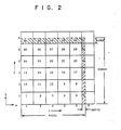
- Figure 2 is a representation of a mosaic image which has been resolved in into an exemplary sequence of thirty-six image segments for digitization and storage in image memory 50. Note that the sequence depicted starts with the first image segment at the lower left corner of the mosaic and after following a serpentine path, ends in the upper left corner. This particular image segment sequence appears to be one of several efficient ways to proceed in that it minimizes stage motion.
- i, j column and row indexes are conventional right-hand coordinate system first quadrant descriptors and refer to a corresponding indexed image segment location in the mosaic.
- Fortran 77 syntax has been used to express the equations to facilitate their comprehension.
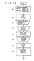
- FIGS 3A through 3D detail the preliminary steps and Figures 3E through 3H describe the automatic sequencing steps of the method that can be implemented in the system of Figure 1.
- Steps 111 and 112 of Figure 3A initialize the system and specify mosaic and vignette dimensions (pixels) preparatory to capturing a mosaic image.
- Specification of vignette dimensions in Step 111 eliminates portions of the video camera raster that suffer from excessive geometrical distortion.
- Choice of the vignette dimensions in pixels dictates the dimensions in pixels of the image segments.
- Steps 113 through 118 allow the operator to capture a low-magnification low resolution image using a 1X objective, and to display the digitized image on monitor 24A. This static low-magnification image will be used to allow the operator to interactively specify the location and extent of the mosaic image.
- Figure 3B shows steps 211 through 221 that enable the operator to: (1) select an appropriate microscope objective (step 212) and scale pixel size accordingly (step 213) using a look-up table set of values obtained by prior calibration; (2) compute the maximum size of the resulting mosaic image that can be stored in image memory (step 214) given the pixel NICOL, NIROW parameters (previous step 111) and the selected pixel size (step 213); (3) display the computed mosaic (x, y) limits with a mosaic image marker (MIM) on the low-magnification low-resolution static image (step 215); and (4) compute remainder pixels (NXPIX, NYPIX) (step 220) and establish the number of vignettes in x and y'directions (NX, NY) needed to produce the complete mosaic (step 221).
- MIM mosaic image marker
- the mosaic image marker displays the boundary outlining the mosaic on the static low-magnification low-resolution image on monitor 24A and is positionable on the screen using keyboard commands from terminal 42.
- the operator designates the lower left (step 216) and upper right (step 217) limits of the mosaic for establishing values of the starting coordinates (IXBEG, IYBEG) and the coordinates of succeeding vignettes and for determining the total number of'pfxels in the x and y directions needed to cover the extent of the mosaic image (NICOL, NIROW).
- Entry points 211a, 215a and 217a of Figure 3B are available to the operator to make changes to the objective lens selection, and to the starting and ending points on the mosaic, from choices detailed in Figure 3D.
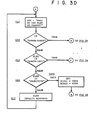
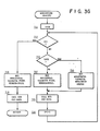
- the steps in the flow diagram of Figure 3C are provided to enable the operator to make the decision whether the NXPIX and NYPIX remainder pixels need to be included in the mosaic. If these pixels are not needed (steps 312 through 315), vignette processing time is considerably shortened. For example, with reference to Figure 2, should SNAP be elected (i.e., discard the remainder pixels) then the vignette sequence from the 36 possibles in this example would run 1, 2, 3, 4, 5, 8, 9, 10, 11, 12, 13, 14, 15, 16, 17, 20, 21, 22, 23, 24, 25, 26, 27, 28 and 29 (a savings of about 1/3 the processing time).
- Steps 316 through 321 the full sequence of 36 vignettes are recorded, with unfilled pixel bits appearing black in the digitized image displayed on monitor 24.
- Step 322 provides an opportunity for the operator to change the input parameters should he see that the display of the MIM (step 315) on monitor 24A does not cover the region required. Recall that the MIM characterizes the size of the mosaic image relative to the low-magnification low-resolution image of the specimen.
- Figure 3E shows a set of steps, including the use of two subroutines, that provide for the sequential stepping of the microscope stage 30 on a serpentine path through the object plane of microscope 10 and digitizing for storage in image memory 50, a corresponding vignette at each step.
- next line is sequenced from right to left with subroutine "GO LEFT" as soon as the (j) loop counter is incremented at the conclusion of digitizing the last vignette on the line.
- the process terminates.
- Steps 612 through 615 comprise a simple loop to acquire the horizontal sequence of vignettes.
- Step 612 tests for the final vignette on the row. If the current one is the final one, then steps 616 and 617 account for the possibility that the last vignette is a partial one.
- the GO LEFT sequence in Figure 3G is similar, with the exception that the possible partial vignette is the first one encountered in this case, rather than the last.
- Step 811 uses the (i, j) indices passed from the calling routine to compute the stage coordinates for the current vignette, while step 812 drives the stage to the computed coordinates.
- Step 813 computes the corresponding image memory x and y addresses.
- Step 814 allows the operator to focus the live video image on viewing monitor 24.
- step 815 the image is digitized and in step 816 the vignette is transferred to the image memory with coordinates that were computed in step 813.
- the mosaic image may be recalled for viewing and manipulation using a variety of techniques, including roam and zoom, contrast enhancement, false coloring and spatial filtering, or even automatic feature detection and analysis.
- the large high-resolution mosaic image can be stored on disk, requiring a storage capacity of up to 16 Mbytes per image.
- An alternative for archival storage is a high performance 9-track tape drive system.
- mapping In addition to providing means for automatic digital analysis of wide-field high-resolution images, the present invention also comprehends manually driven scene analysis, herein referred to as mapping. This method relies on the ability of the system to electronically superimpose graphical marks over the electronically captured image.
- mapping marks may be continously generated from the cursor coordinates, analogous to ink flowing from a pen.
- the marks are displayed by replacing the image pixel value in image memory by a new value which is displayed as a high contrast color.
- Alternative means for storage of the marks is possible, for example, storage in the image memory bits unoccupied by image data or in a graphics overlay plane.
- the coordinates of the marks are also stored numerically as a vector list for further processing and analysis.
- mapping in the context of a high-resolution wide-field-of-view electronic mosaic image, it will also be appreciated that high-resolution wide-field images sensed and stored by any means whatsoever (for example, laser scanner, remote sensor, scanning electron microscope, or line scan camera) lend themselves to this method of electronic mapping.
- any means whatsoever for example, laser scanner, remote sensor, scanning electron microscope, or line scan camera
- the video camera Since electronic mosaic imaging requires that the edges of adjacent vignettes be precisely matched, the video camera must be one that produces a raster that is accurately aligned with the translation axes and generates a pixel size that is accurately known. A shading correction may be needed to eliminate the edge effects between adjacent image segments, particularly if quantitative photometric density measurements are to be made directly from the image.
- microscope embodiment described here; i comprises a positionable stage with fixed micrc.;cope optics
- the method described herein has already been found useful for imaging a field of fluorescently labeled cells in which the labeled cells could be accurately discerned only by using high-magnification, high N.A. objectives, while the object field of interest containing such cells extended over multiple, high-magnification microscope fields-of-view across the section.
Abstract
Description
- This invention relates to an imaging system with computer-controlled, multiple electronic image acquisition and assembly means for producing a high resolution, large-field electronic mosaic image from a series of smaller field image segments.
- In the field of microscopy, a microscopist must select an objective lens that affords sufficient spatial resolution and photometric sensitivity to analyze a specimen. Having selected an objective, in many cases, the resulting microscopic field of view covers only a small region of the specimen. Consequently, in order to examine the entire specimen, it is necessary to move the microscope stage in a plurality of steps. A single view of the entire specimen, however, is necessary both for contextual appreciation and for communicating the results of the analysis. The classical solution to this problem has been to prepare photomicrographs of the fields of view containing the specimen and to assemble a montage or mosaic of the photomicrographs to present a view of the whole specimen. This procedure suffers from several disadvantages: it is both tedious and time-consuming and results in a final product that is either too large or has insufficient magnification.
- In current practice one often needs to acquire a video image of a microscopically-viewed specimen.
- Microscope video systems, by appropriate interfacing with computer-based hardware and software, permit the video image to be digitized and stored. Further operations, such as image processing and analysis, can then be performed on the digitized image. The present art, however, is unable to process more than a single digitized microscope field of view at a time, which creates difficulties in analysis and display of the complete specimen. In addition, in cases where the microscopic specimen is only briefly visible, as in the case where rapidly-fading fluorescent tags are used, rapid, multiple-field acquisition is a necessity. Solutions to these problems have not previously been available.
- The present invention provides a means for the sequential capture and storage in a very large image memory of multiple digitized and frame-averaged small field image segments from adjacent fields of view. In addition, the invention provides means for matching the edges of the adjacent segments into a continuous field. Means are also provided for storage of the electronic mosaic image, and for real-time manipulation of the entire mosaic by the operator. The resulting composite digitized mosaic image simultaneously offers high resolution, high photometric sensitivity, and a wide field of view, while providing the advantages of electronic digital processing and analysis.
-
- FIG. 1 is a block diagram of one embodiment of the system of this invention.
- FIG. 2 is a graph of a typical image segment sequencing plan used to form a mosaic image.
- FIGS. 3A-3H are flow diagrams detailing the method of the invention.
- The concept of the invention herein described comprehends a computer-controlled, image processor system which automatically digitizes a sequence of magnified individual image segments from an object and composes the image segments into a single high-resolution wide-field-of-view mosaic image for recall and viewing on a CRT monitor. More specifically, the invention herein resides in a method for producing a high-resolution large-field-of-view electronic mosaic image of an object within an object plane by computer-controlled, multiple electronic image acquisition and assembly means, which method comprises in sequence:
- a) selecting a field of interest within the object plane;
- b) defining the pixel size in the object plane;
- c) computing the number of image pixels in the x and y directions required to cover the field of interest in the object plane;
- d) determining the number of pixels in the x and y directions of each image segment;
- e) computing image segment size in the object plane;
- f) determining the position of each image segment in the object plane and the sequence in which the image segments will be acquired;
- g) positioning the object with respect to an image sensor so that the initial image segment position in the sequence lies on the image sensor optical axis;
- h) digitizing the field of view of the image sensor;
- i) transferring the digitized field of view to a contiguous set of x,y locations in a mosaic image storage means corresponding to the image segment position in the object plane;
- j) positioning the object with respect to the image sensor so that the next image segment position in the sequence lies on the image sensor optical axis;
- k) digitizing the field of view of the image sensor;
- 1) transferring the digitized field of view to a contiguous set of x,y locations in the mosaic image storage means corresponding to the image segment position in the object plane, said correspondence being chosen such that the boundaries of adjacent image segments in the mosaic image storage means are in substantial abutment and alignment;
- m3 repeating steps (j), (k), and (1) until all image segments in the sequence have been digitized and stored in the mosaic image storage means; and
- n) recalling the mosaic image from the mosaic image storage means.
- The invention also resides in a method of producing a graphical map from a stored wide-field-of-view high-resolution electronic image, the method comprising the steps:
- a) displaying a contiguous small portion of the stored wide-field-of-view high-resolution electronic image on a display monitor, said portion at any instant in time being within a display window;
- b) displaying an electronic visible cursor, superimposed on the displayed image, at a fixed location within the display window;
- c) roaming the display window within the stored wide-field-of-view high-resolution electronic image under operator control;
- d) generating mapping marks under operator control from the fixed cursor position within the display window, said marks being stored in juxtaposition with the image, made visible on the display, and roamed in coincidence with the image portion visible in the display window such that accurate juxtaposition of the marks with the image is maintained; and
- e) storing the x,y coordinates of the marks in a separate memory.
- The operator first selects parameters which will govern acquisition of the mosaic image, including the x,y coordinates of, for example, the lower-left corner of the mosaic image, correspondingly, the x,y coordinates of the upper right corner of the image, and the objective magnification. The basic pixel size in x and y are then automatically computed, as well as the number of mosaic image pixels in x and y and the number of image segments in x and y. The computer-driven microscope stage is then automatically advanced to the coordinates corresponding to the lower left corner of the mosaic image. A video image of this field of view is then digitized, and a previously defined central portion (called a "vignette") is transferred to contiguous addresses within a large image memory which correspond to the lower left region of the image. The stage is then advanced by a distance which exactly equals the spatial extent of one vignette image, and the process is repeated in a predetermined path in x and y until the entire mosaic image has been acquired.
- Once assembled, the operator is able to interactively manipulate the mosaic image in various ways, including zooming and roaming, much as he would do with the live image on the microscope by changing objectives and manipulating the stage. The invention permits viewing the high-resolution mosaic image on a standard-resolution monitor by means of pixel sampling. For example, a 4096 x 4096 pixel mosaic image can be displayed on a 512 x 512 pixel display monitor using a sampling ratio of 1:8. Thus, zoom up to a one-to-one sampling ratio is achieved without the loss in resolution that would accompany pixel replication methods.
- A benefit of the method is that of preserving the high-resolution image of a specimen obtained from high numerical aperture (N.A.) optics over the wide field of view image normally seen through low power, low N.A. objectives. Another benefit of using high N.A. objectives is their improved light collection efficiency. Further, ―' the invention minimizes the time that the specimen needs to be exposed to illumination. This combination is particularly applicable to those cases where the microscopic specimen is so light-sensitive that prolonged viewing of the live image through microscope occulars would have an adverse effect on the specimen, for example, in the case where rapidly-fading fluorescent tags are used. A further benefit results from the fact that because the mosaic image is displayed on a video monitor by pixel sampling, the contribution of the camera's point spread function to overall image blur is significantly reduced and the displayed image appears much more crisply resolved.
- For purposes of illustration, the embodiment of Figure 1 includes a
microscope 10, typically a Nikon Fluophot, with anultrawide Optiphot head 12 that is modified for mounting two standardformat video cameras Video camera 14 is a DAGE/MTI Model 68 silicon diode array vidicon, andvideo camera 16 is a DAGE/MTI Corporation Model 66 with a silicon intensified target (SIT) tube for low light level sensing. The outputs ofcameras image processor 18, typically an Imaging Technology, Inc. IP-512 system that includes three FB-512 boards, two AP-512 boards and an arithmetic logic unit (ALU) board, which communicates with the other components of the imaging system over the 22-bit Digital Equipment Co. (DEC) Q-bus 20.Image processor 18 functions to synchronize the input and output flow of digital image data, to digitize the analog camera output information, and to convert the processed digital data into analog form for viewing on display monitors 24 and 24A. Both displays are high-resolution color monitors (Mitsubishi Electronics of America, Inc. Model No. 3919). - The microscope stage assembly 30 comprises a Nikon Diaphot stage on which are mounted two Burleigh Instruments Inc. IW-502 inchworm x,y micropositioners and EN-372
optical encoders Stage controller 38 comprises an Intel Corporation Model No. 8085 microprocessor for providing closed-loop control for both sets of positioners and encoders with I/O codes on an STD bus. The microprocessor is also programmed to communicate with ahost computer system 40 over Q-bus 20. The inchworm micropositioners enable the operator to rapidly and smoothly move the stage across its full range of travel. Typical performance yields 1.0 micrometer absolute accuracy on 2 axes bidirectionally over a range of 50 mm on each axis. Both axes' positions are under simultaneous closed loop control, with position feedback derived from 1 micrometer linear optical encoders. Consequently, the stage can be moved and returned to its initial position with 1 micrometer accuracy and with no backlash. The communications interface with the host processor is able to support at least 150 coordinate pair updates per second. -
Computer system 40 comprises: aDEC LSI 11/23 computer which includes Q-bus 20; a 256 Kbyte main memory; a DLV-11J quad serial data interface; a Data Systems Design, Inc. Model No. DSD 880 30 Mbyte Winchester disk drive with a 1/2 Mbyte floppy disk; a Cipher Data Products Inc. M891, 9-track 3200 bpi cache streamer magnetic tape drive; a Microline hard copy printer manufactured by Okidata Corporation; a Hewlett Packard 7475A six pen plotter; and a DEC Model No.DRV 11 parallel interface to thestage controller 38. Communicating withcomputer 40 is a DEC Model No.VT100 Terminal 42. -
Image memory 50 and direct memory access (DMA) data-mover controller 52 (Image Analytics Corporation Model QD512) are hardwired circuits that communicate directly with the I/O section of the host computer on Q-bus 20 to speed up the delivery of image size and stage position coordinate data, with the result that the display of the respective vignettes on themonitor 24 is rapidly achieved. - The
image memory 50 comprises a stack of four addressable memory boards, each with a 4 Mbyte (8 bits per byte) capacity, to provide storage for a 16 Mbyte, 4096 x 4096 pixel image with full eight bits/pixel resolution. -
Datamover controller 52 is a direct memory access (DMA) device capable of transferring data at high speed from a source address to a destination address on 0-bus 20. It is also responsible for selecting, as directed, an N x N pixel segment fromimage memory 50 for full display on themonitor 24. - In the operation of the system, the operator places a specimen on the microscope stage assembly 30, selects a 1X objective lens, and selects either the normal 14 or low-light-
level video camera 16. Live video from the camera is displayed onmonitor 24, and the operator uses this low-magnification low-resolution live video image to focus and frame the desired section of the specimen. The stage is then fixed, the image on themonitor 24 is digitized, transferred to a static frame buffer, and displayed as a low-magnification static image onmonitor 24A. The operator then selects an objective lens with suitable resolution to acquire each image segment. The calibrated image pixel size DX and DY for this objective are obtained from a look-up table, and the maximum mosaic image size is computed and displayed as a rectangular mosaic image marker (MIM) that is drawn superimposed on the static low-magnification low-resolution image onmonitor 24A. The operator manipulates, in this case, the lower-left and upper-right corners of the MIM independently to frame the area of interest. Once the MIM is set, the stage coordinates of the lower left starting position are computed, as well as the number and positions of full and partial vignettes required to fill the MIM, as schematized in Figure 2. At this point, the operator then may choose to eliminate partial vignettes at the right and top edges in order to significantly reduce the time required to capture the mosaic image. - Finally, the operator activates the mosaic imaging sequence via the
VT100 terminal 42. Automatically,computer 40 advances the stage assembly 30 to a starting position and then steps it through a sequence of positions viastage controller 38. Each programmed position is precisely located in the center of its respective vignette. At each position, the acquired image segment from eithervideo cameras image processor 18 to monitor 24, which the operator observes while critically focussing the stage.Image processor 18 then digitizes, frame-averages, and temporarily stores the 512 x 512 pixel video image for viewing onmonitor 24A. A rectangular central portion of this video image, called a vignette, is transferred to imagememory 50, as directed by theimage DMA controller 52. - The mosaic imaging sequence is complete when the assigned portion of the full 4096 x 4096 pixel image memory has been filled by the sequence of vignettes that have been acquired and stored in their respective image memory locations.
- To one skilled in the art, the following flow charts and description are sufficient to develop software needed to operate the microscope system disclosed herein.
- Figure 2 is a representation of a mosaic image which has been resolved in into an exemplary sequence of thirty-six image segments for digitization and storage in
image memory 50. Note that the sequence depicted starts with the first image segment at the lower left corner of the mosaic and after following a serpentine path, ends in the upper left corner. This particular image segment sequence appears to be one of several efficient ways to proceed in that it minimizes stage motion. - In the definitions following, the i, j column and row indexes are conventional right-hand coordinate system first quadrant descriptors and refer to a corresponding indexed image segment location in the mosaic. Fortran 77 syntax has been used to express the equations to facilitate their comprehension.


- Figures 3A through 3D detail the preliminary steps and Figures 3E through 3H describe the automatic sequencing steps of the method that can be implemented in the system of Figure 1.
-
Steps Step 111 eliminates portions of the video camera raster that suffer from excessive geometrical distortion. Choice of the vignette dimensions in pixels dictates the dimensions in pixels of the image segments.Steps 113 through 118 allow the operator to capture a low-magnification low resolution image using a 1X objective, and to display the digitized image onmonitor 24A. This static low-magnification image will be used to allow the operator to interactively specify the location and extent of the mosaic image. - Figure 3B shows
steps 211 through 221 that enable the operator to: (1) select an appropriate microscope objective (step 212) and scale pixel size accordingly (step 213) using a look-up table set of values obtained by prior calibration; (2) compute the maximum size of the resulting mosaic image that can be stored in image memory (step 214) given the pixel NICOL, NIROW parameters (previous step 111) and the selected pixel size (step 213); (3) display the computed mosaic (x, y) limits with a mosaic image marker (MIM) on the low-magnification low-resolution static image (step 215); and (4) compute remainder pixels (NXPIX, NYPIX) (step 220) and establish the number of vignettes in x and y'directions (NX, NY) needed to produce the complete mosaic (step 221). - The mosaic image marker (MIM) displays the boundary outlining the mosaic on the static low-magnification low-resolution image on
monitor 24A and is positionable on the screen using keyboard commands fromterminal 42. By positioning the MIM, the operator designates the lower left (step 216) and upper right (step 217) limits of the mosaic for establishing values of the starting coordinates (IXBEG, IYBEG) and the coordinates of succeeding vignettes and for determining the total number of'pfxels in the x and y directions needed to cover the extent of the mosaic image (NICOL, NIROW). -
Entry points - The steps in the flow diagram of Figure 3C are provided to enable the operator to make the decision whether the NXPIX and NYPIX remainder pixels need to be included in the mosaic. If these pixels are not needed (
steps 312 through 315), vignette processing time is considerably shortened. For example, with reference to Figure 2, should SNAP be elected (i.e., discard the remainder pixels) then the vignette sequence from the 36 possibles in this example would run 1, 2, 3, 4, 5, 8, 9, 10, 11, 12, 13, 14, 15, 16, 17, 20, 21, 22, 23, 24, 25, 26, 27, 28 and 29 (a savings of about 1/3 the processing time). On the other hand, should SNAP not be selected (steps 316 through 321), then the full sequence of 36 vignettes are recorded, with unfilled pixel bits appearing black in the digitized image displayed onmonitor 24. Step 322 provides an opportunity for the operator to change the input parameters should he see that the display of the MIM (step 315) onmonitor 24A does not cover the region required. Recall that the MIM characterizes the size of the mosaic image relative to the low-magnification low-resolution image of the specimen. - Figure 3E shows a set of steps, including the use of two subroutines, that provide for the sequential stepping of the microscope stage 30 on a serpentine path through the object plane of
microscope 10 and digitizing for storage inimage memory 50, a corresponding vignette at each step. After j=l initialization of a loop counter instep 512, step 515 tests to determine whether the vignette recording sequence moves from left to right with subroutine "GO RIGHT",step 517, or from right to left with subroutine "GO LEFT",step 516. Since j=l is odd the former subroutine "GO RIGHT" is selected. Similarly, the next line is sequenced from right to left with subroutine "GO LEFT" as soon as the (j) loop counter is incremented at the conclusion of digitizing the last vignette on the line. When the last row is encountered instep 518, the process terminates. - Subroutines GO RIGHT and GO LEFT are detailed in Figures 3F and 3G, respectively. In Figure 3F, the vignette column counter is initialized in
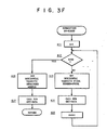
step 611.Steps 612 through 615 comprise a simple loop to acquire the horizontal sequence of vignettes. Step 612 tests for the final vignette on the row. If the current one is the final one, then steps 616 and 617 account for the possibility that the last vignette is a partial one. The GO LEFT sequence in Figure 3G is similar, with the exception that the possible partial vignette is the first one encountered in this case, rather than the last. - Both directional sequences use subroutine GET_DATA, Figure 3H, to carry out stage motion, image digitization, and data transfer to image memory. Step 811 uses the (i, j) indices passed from the calling routine to compute the stage coordinates for the current vignette, while
step 812 drives the stage to the computed coordinates. Step 813 computes the corresponding image memory x and y addresses. Step 814 allows the operator to focus the live video image on viewingmonitor 24. Instep 815 the image is digitized and instep 816 the vignette is transferred to the image memory with coordinates that were computed instep 813. - Once the mosaic image has been composed in
image memory 50, it may be recalled for viewing and manipulation using a variety of techniques, including roam and zoom, contrast enhancement, false coloring and spatial filtering, or even automatic feature detection and analysis. The large high-resolution mosaic image can be stored on disk, requiring a storage capacity of up to 16 Mbytes per image. An alternative for archival storage is a high performance 9-track tape drive system. - In addition to providing means for automatic digital analysis of wide-field high-resolution images, the present invention also comprehends manually driven scene analysis, herein referred to as mapping. This method relies on the ability of the system to electronically superimpose graphical marks over the electronically captured image.
- Note that if a given display pixel corresponds with exactly one stored mosaic image pixel, in general, a very small spatial extent of the mosaic image appears on the display monitor. This portion is referred to herein as the "display window"; as noted earlier, it is possible to roam the window throughout the stored mosaic image. The operator proceeds to create a map by "flying" the display window within the context of the mosaic image. Displayed on the monitor will be a fixed video cursor superimposed on the image, indicating the current addressed cartesian coordinates in the stored image. When the operator so indicates, mapping marks may be continously generated from the cursor coordinates, analogous to ink flowing from a pen. The marks are displayed by replacing the image pixel value in image memory by a new value which is displayed as a high contrast color. Alternative means for storage of the marks is possible, for example, storage in the image memory bits unoccupied by image data or in a graphics overlay plane. The coordinates of the marks are also stored numerically as a vector list for further processing and analysis. Optionally, it is possible for the operator to indicate discrete objects by discrete rather than continuous generation of mapping marks.
- In addition to allowing mapping in the context of a high-resolution wide-field-of-view electronic mosaic image, it will also be appreciated that high-resolution wide-field images sensed and stored by any means whatsoever (for example, laser scanner, remote sensor, scanning electron microscope, or line scan camera) lend themselves to this method of electronic mapping.
- There are two sources of geometrical distortion in an individual digitized image. They are distortion in the camera raster and in microscope optics. Each of them must be made small for accurate matching at the vignette boundaries. Solid state video cameras offer low geometrical distortion, although many other devices for image scanning can be readily applied, such as, e.g., line scan cameras, laser scanners, and flying spot scanners. Plan-apochromatic objectives appear to be adequate to minimize distortion. In cases where high photometric sensitivity is required, a high-sensitivity vidicon-based camera (such as a silicon intensified target (SIT) camera) is appropriate.
- Since electronic mosaic imaging requires that the edges of adjacent vignettes be precisely matched, the video camera must be one that produces a raster that is accurately aligned with the translation axes and generates a pixel size that is accurately known. A shading correction may be needed to eliminate the edge effects between adjacent image segments, particularly if quantitative photometric density measurements are to be made directly from the image.
- Although the microscope embodiment described here; i comprises a positionable stage with fixed micrc.;cope optics, it may be beneficial under some circumstances to fix the specimen stage and obtain vignette positioning by translati g the microscope optics themselves. It will be understoo; that this method is within the spirit of the invention.
- Although the principle of this invention has bee1 described in the context of a monochromatic optical microscopical imaging system, further applications of electronic mosaic imaging are envisioned, including other forms of microscopy, such as electron, X-ray, infrared, and acoustical imaging schemes, as well as assemblage from a non-microscopic two-dimensional image source such as, for example, a photographic image or series of images, thermographic images, or printed circuit boards.
- The method described herein has already been found useful for imaging a field of fluorescently labeled cells in which the labeled cells could be accurately discerned only by using high-magnification, high N.A. objectives, while the object field of interest containing such cells extended over multiple, high-magnification microscope fields-of-view across the section.
- Another example in which the technique has been found useful is the imaging of receptor autoradiographic material in which the radioactive label covers essentially the entire tissue section, yet the grains in the photographic emulsion forming the analytical signal can only be resolved at relatively high magnification. Accurate distinction between the autoradiographic analytical signal and light absorption in the underlying tissue section requires this level of magnification. Thus, accuracy in the quantitation of receptor autoradiograms is improved by the method of the present invention in comparison with methods relying on a single low-magnification field-of-view.
Claims (19)
Applications Claiming Priority (2)
| Application Number | Priority Date | Filing Date | Title |
|---|---|---|---|
| US06/725,636 US4673988A (en) | 1985-04-22 | 1985-04-22 | Electronic mosaic imaging process |
| US725636 | 1985-04-22 |
Publications (2)
| Publication Number | Publication Date |
|---|---|
| EP0199573A2 true EP0199573A2 (en) | 1986-10-29 |
| EP0199573A3 EP0199573A3 (en) | 1989-05-31 |
Family
ID=24915369
Family Applications (1)
| Application Number | Title | Priority Date | Filing Date |
|---|---|---|---|
| EP86302979A Withdrawn EP0199573A3 (en) | 1985-04-22 | 1986-04-21 | Electronic mosaic imaging process |
Country Status (7)
| Country | Link |
|---|---|
| US (1) | US4673988A (en) |
| EP (1) | EP0199573A3 (en) |
| JP (1) | JPS61248168A (en) |
| AU (2) | AU568242B2 (en) |
| CA (1) | CA1284375C (en) |
| DK (1) | DK181986A (en) |
| GR (1) | GR861042B (en) |
Cited By (7)
| Publication number | Priority date | Publication date | Assignee | Title |
|---|---|---|---|---|
| GB2197154A (en) * | 1986-11-04 | 1988-05-11 | Harry Scala | Graphic animation stand |
| EP0270319A2 (en) * | 1986-12-03 | 1988-06-08 | Logistics Data Systems, Inc. | Video C.A.D. system |
| GB2239762A (en) * | 1989-10-11 | 1991-07-10 | Messerschmitt Boelkow Blohm | Panoramic imaging system |
| EP0852363A2 (en) * | 1997-01-02 | 1998-07-08 | Runaway Technology, Inc. | Digital composition of a mosaic image |
| EP1008956A1 (en) * | 1998-12-08 | 2000-06-14 | Synoptics Limited | Automatic image montage system |
| WO2008012059A3 (en) * | 2006-07-28 | 2009-03-05 | Zeiss Carl Microimaging Gmbh | Microscope image processing method, computer, computer program and data storage medium |
| EP1235424A3 (en) * | 2001-02-24 | 2009-09-02 | Carl Zeiss | Method for recording and displaying fluorescence images with high resolution |
Families Citing this family (108)
| Publication number | Priority date | Publication date | Assignee | Title |
|---|---|---|---|---|
| GB8511624D0 (en) * | 1985-05-08 | 1985-06-12 | E P R Bureau Ltd | Scanning system |
| US4777525A (en) * | 1985-12-23 | 1988-10-11 | Preston Jr Kendall | Apparatus and method for a multi-resolution electro-optical imaging, display and storage/retrieval system |
| AU580923B2 (en) * | 1986-02-14 | 1989-02-02 | Sharp Kabushiki Kaisha | Image reader |
| EP0272886A3 (en) * | 1986-12-19 | 1990-12-19 | Pfu Limited | Image information processing system |
| US4801809A (en) * | 1987-07-13 | 1989-01-31 | Process Automation Business, Inc. | Sheet inspection apparatus and methods providing simultaneous resolution of measurement zones and wavelength bands |
| US5131080A (en) * | 1987-08-18 | 1992-07-14 | Hewlett-Packard Company | Graphics frame buffer with RGB pixel cache |
| US5994698A (en) * | 1987-09-24 | 1999-11-30 | Canon Kabushiki Kaisha | Microprobe, preparation thereof and electronic device by use of said microprobe |
| US4958241A (en) * | 1988-06-16 | 1990-09-18 | Kabushiki Kaisha Topcon | Image input apparatus |
| JPH0279172A (en) * | 1988-09-16 | 1990-03-19 | Fuji Photo Film Co Ltd | Picture inputting method |
| FR2644263B1 (en) * | 1989-03-13 | 1991-06-14 | Matra Sep Imagerie Inf | METHOD AND DEVICE FOR THE ACQUISITION AND DIGITAL STORAGE OF COLORED GEOGRAPHIC MAPS AND FOR RETURNING THESE MAPS |
| US5191429A (en) | 1990-09-28 | 1993-03-02 | Xerox Corporation | Electronic printing system for printing multiple images with determination of the maximum number of reduced size images to be optimally printed on a sheet of detected size without interference |
| US5212383A (en) * | 1991-07-29 | 1993-05-18 | David Scharf | Color synthesizing scanning electron microscope |
| US5321798A (en) * | 1991-10-28 | 1994-06-14 | Hughes Aircraft Company | Apparatus for providing a composite digital representation of a scene within a field-of-regard |
| JP3206060B2 (en) * | 1991-12-26 | 2001-09-04 | ミノルタ株式会社 | Image editing device |
| US5912699A (en) * | 1992-02-18 | 1999-06-15 | Neopath, Inc. | Method and apparatus for rapid capture of focused microscopic images |
| US5699442A (en) * | 1992-04-10 | 1997-12-16 | Andrew Welch | System for detecting the location of a reflective object within a video field |
| US5517235A (en) * | 1993-11-03 | 1996-05-14 | Control Automation, Inc. | Method and apparatus for inspecting printed circuit boards at different magnifications |
| DE69738996D1 (en) * | 1996-05-30 | 2008-10-30 | Cellomics Inc | MINIATURIZED CELL ARRANGEMENT AND METHOD AND DEVICE FOR SCREENING BY CELLS |
| US6103479A (en) * | 1996-05-30 | 2000-08-15 | Cellomics, Inc. | Miniaturized cell array methods and apparatus for cell-based screening |
| US5989835A (en) * | 1997-02-27 | 1999-11-23 | Cellomics, Inc. | System for cell-based screening |
| US20060141539A1 (en) * | 1996-05-30 | 2006-06-29 | Taylor D L | Miniaturized cell array methods and apparatus for cell-based screening |
| US6404906B2 (en) * | 1997-03-03 | 2002-06-11 | Bacus Research Laboratories,Inc. | Method and apparatus for acquiring and reconstructing magnified specimen images from a computer-controlled microscope |
| US6272235B1 (en) * | 1997-03-03 | 2001-08-07 | Bacus Research Laboratories, Inc. | Method and apparatus for creating a virtual microscope slide |
| US6396941B1 (en) * | 1996-08-23 | 2002-05-28 | Bacus Research Laboratories, Inc. | Method and apparatus for internet, intranet, and local viewing of virtual microscope slides |
| US6008010A (en) * | 1996-11-01 | 1999-12-28 | University Of Pittsburgh | Method and apparatus for holding cells |
| JPH10172490A (en) * | 1996-12-10 | 1998-06-26 | Hitachi Ltd | Scan electron microscope |
| US7117098B1 (en) | 1997-02-27 | 2006-10-03 | Cellomics, Inc. | Machine-readable storage medium for analyzing distribution of macromolecules between the cell membrane and the cell cytoplasm |
| CA2282658C (en) | 1997-02-27 | 2003-02-25 | Cellomics, Inc. | A system for cell-based screening |
| US6727071B1 (en) | 1997-02-27 | 2004-04-27 | Cellomics, Inc. | System for cell-based screening |
| US6249616B1 (en) | 1997-05-30 | 2001-06-19 | Enroute, Inc | Combining digital images based on three-dimensional relationships between source image data sets |
| US6370487B1 (en) | 1998-04-23 | 2002-04-09 | Micron Technology, Inc. | Remote semiconductor microscopy |
| US6313452B1 (en) * | 1998-06-10 | 2001-11-06 | Sarnoff Corporation | Microscopy system utilizing a plurality of images for enhanced image processing capabilities |
| US6847729B1 (en) | 1999-04-21 | 2005-01-25 | Fairfield Imaging Limited | Microscopy |
| AUPQ027799A0 (en) | 1999-05-10 | 1999-06-03 | Canon Information Systems Research Australia Pty Ltd | Altering the shape of an artwork |
| US6995794B2 (en) * | 1999-06-30 | 2006-02-07 | Logitech Europe S.A. | Video camera with major functions implemented in host software |
| AU1182401A (en) * | 1999-10-15 | 2001-04-23 | Cellavision Ab | Microscope and method for manufacturing a composite image with a high resolution |
| US20060073509A1 (en) * | 1999-11-18 | 2006-04-06 | Michael Kilpatrick | Method for detecting and quantitating multiple subcellular components |
| WO2001042786A2 (en) | 1999-12-09 | 2001-06-14 | Cellomics, Inc. | System for cell based screening : cell spreading |
| US6711283B1 (en) * | 2000-05-03 | 2004-03-23 | Aperio Technologies, Inc. | Fully automatic rapid microscope slide scanner |
| US7518652B2 (en) * | 2000-05-03 | 2009-04-14 | Aperio Technologies, Inc. | Method and apparatus for pre-focus in a linear array based slide scanner |
| US7738688B2 (en) | 2000-05-03 | 2010-06-15 | Aperio Technologies, Inc. | System and method for viewing virtual slides |
| US7668362B2 (en) | 2000-05-03 | 2010-02-23 | Aperio Technologies, Inc. | System and method for assessing virtual slide image quality |
| DE10026392A1 (en) * | 2000-05-27 | 2001-11-29 | Leica Microsystems | Method and arrangement for coding live images in microscopy |
| US20020084981A1 (en) * | 2000-11-14 | 2002-07-04 | Flack James F. | Cursor navigation system and method for a display |
| AUPR788101A0 (en) * | 2001-09-24 | 2001-10-18 | Canon Information Systems Research Australia Pty Ltd | Scanning and detecting a number of images |
| US20030210262A1 (en) * | 2002-05-10 | 2003-11-13 | Tripath Imaging, Inc. | Video microscopy system and multi-view virtual slide viewer capable of simultaneously acquiring and displaying various digital views of an area of interest located on a microscopic slide |
| ES2222853T1 (en) * | 2002-07-15 | 2005-02-16 | Baylor College Of Medicine | EVALUATION AND IMAGE SYSTEM THAT IDENTIFIES CHARACTERISTICS OF BIOLOGICAL SPECIMENS. |
| WO2004025331A2 (en) * | 2002-09-16 | 2004-03-25 | Rensselaer Polytechnic Institute | Microscope with extended field of vision |
| US7424133B2 (en) * | 2002-11-08 | 2008-09-09 | Pictometry International Corporation | Method and apparatus for capturing, geolocating and measuring oblique images |
| GB2398196B (en) | 2003-02-05 | 2005-06-01 | Fairfield Imaging Ltd | Microscope system and method |
| US7257268B2 (en) | 2003-02-28 | 2007-08-14 | Aperio Technologies, Inc. | Systems and methods for image pattern recognition |
| US7116440B2 (en) | 2003-02-28 | 2006-10-03 | Aperio Technologies, Inc. | Image processing and analysis framework |
| DE102004024810A1 (en) * | 2004-05-17 | 2005-12-08 | Soft Imaging System Gmbh | Method and apparatus for optically scanning a sample |
| JP5134365B2 (en) * | 2004-05-27 | 2013-01-30 | アペリオ・テクノロジーズ・インコーポレイテッド | System and method for generating and visualizing a three-dimensional virtual slide |
| DE102004056698B3 (en) * | 2004-11-24 | 2006-08-17 | Stratus Vision Gmbh | Inspection device for a substrate having at least one printed layer |
| JP5336088B2 (en) | 2005-01-27 | 2013-11-06 | アペリオ・テクノロジーズ・インコーポレイテッド | System and method for visualizing a three-dimensional virtual slide |
| US9789608B2 (en) | 2006-06-29 | 2017-10-17 | Intuitive Surgical Operations, Inc. | Synthetic representation of a surgical robot |
| DE102005024066A1 (en) | 2005-05-25 | 2006-12-07 | Soft Imaging System Gmbh | Method and apparatus for optically scanning a sample |
| US8164622B2 (en) * | 2005-07-01 | 2012-04-24 | Aperio Technologies, Inc. | System and method for single optical axis multi-detector microscope slide scanner |
| DE102005047261A1 (en) * | 2005-10-01 | 2007-04-05 | Carl Zeiss Jena Gmbh | Display image production method, involves producing display image of display image sequence from subsequence of two recorded exposure images of exposure image sequence, where number of display images is less than number of exposure images |
| US7930065B2 (en) | 2005-12-30 | 2011-04-19 | Intuitive Surgical Operations, Inc. | Robotic surgery system including position sensors using fiber bragg gratings |
| US9962066B2 (en) | 2005-12-30 | 2018-05-08 | Intuitive Surgical Operations, Inc. | Methods and apparatus to shape flexible entry guides for minimally invasive surgery |
| KR101477121B1 (en) | 2006-06-13 | 2014-12-29 | 인튜어티브 서지컬 인코포레이티드 | Minimally invasive surgical system |
| US10258425B2 (en) | 2008-06-27 | 2019-04-16 | Intuitive Surgical Operations, Inc. | Medical robotic system providing an auxiliary view of articulatable instruments extending out of a distal end of an entry guide |
| US9718190B2 (en) | 2006-06-29 | 2017-08-01 | Intuitive Surgical Operations, Inc. | Tool position and identification indicator displayed in a boundary area of a computer display screen |
| US10008017B2 (en) | 2006-06-29 | 2018-06-26 | Intuitive Surgical Operations, Inc. | Rendering tool information as graphic overlays on displayed images of tools |
| EP2036003B1 (en) | 2006-06-30 | 2017-05-03 | Leica Biosystems Imaging, Inc. | Method for storing and retrieving large images via dicom |
| US8010555B2 (en) | 2006-06-30 | 2011-08-30 | Aperio Technologies, Inc. | System and method for managing images over a network |
| US7873238B2 (en) | 2006-08-30 | 2011-01-18 | Pictometry International Corporation | Mosaic oblique images and methods of making and using same |
| US8593518B2 (en) * | 2007-02-01 | 2013-11-26 | Pictometry International Corp. | Computer system for continuous oblique panning |
| US8520079B2 (en) * | 2007-02-15 | 2013-08-27 | Pictometry International Corp. | Event multiplexer for managing the capture of images |
| US9262818B2 (en) | 2007-05-01 | 2016-02-16 | Pictometry International Corp. | System for detecting image abnormalities |
| US8385672B2 (en) * | 2007-05-01 | 2013-02-26 | Pictometry International Corp. | System for detecting image abnormalities |
| EP2153401B1 (en) | 2007-05-04 | 2016-12-28 | Leica Biosystems Imaging, Inc. | System and method for quality assurance in pathology |
| US8620473B2 (en) | 2007-06-13 | 2013-12-31 | Intuitive Surgical Operations, Inc. | Medical robotic system with coupled control modes |
| US9469034B2 (en) | 2007-06-13 | 2016-10-18 | Intuitive Surgical Operations, Inc. | Method and system for switching modes of a robotic system |
| US9096033B2 (en) | 2007-06-13 | 2015-08-04 | Intuitive Surgical Operations, Inc. | Surgical system instrument sterile adapter |
| US7991226B2 (en) | 2007-10-12 | 2011-08-02 | Pictometry International Corporation | System and process for color-balancing a series of oblique images |
| US8531472B2 (en) | 2007-12-03 | 2013-09-10 | Pictometry International Corp. | Systems and methods for rapid three-dimensional modeling with real façade texture |
| US8588547B2 (en) | 2008-08-05 | 2013-11-19 | Pictometry International Corp. | Cut-line steering methods for forming a mosaic image of a geographical area |
| EP3764085A3 (en) | 2008-10-24 | 2021-03-24 | Leica Biosystems Imaging Inc. | Whole slide fluorescence scanner |
| CA2755164C (en) | 2009-03-11 | 2014-02-25 | Sensovation Ag | Autofocus method and autofocus device |
| US8401222B2 (en) * | 2009-05-22 | 2013-03-19 | Pictometry International Corp. | System and process for roof measurement using aerial imagery |
| US9492927B2 (en) | 2009-08-15 | 2016-11-15 | Intuitive Surgical Operations, Inc. | Application of force feedback on an input device to urge its operator to command an articulated instrument to a preferred pose |
| US9330494B2 (en) | 2009-10-26 | 2016-05-03 | Pictometry International Corp. | Method for the automatic material classification and texture simulation for 3D models |
| JP5786110B2 (en) | 2009-12-11 | 2015-09-30 | ライカ バイオシステムズ イメージング インコーポレイテッドAperio Technologies, Inc. | Improvement of signal-to-noise ratio in digital pathological image analysis |
| US8477190B2 (en) | 2010-07-07 | 2013-07-02 | Pictometry International Corp. | Real-time moving platform management system |
| US10139613B2 (en) | 2010-08-20 | 2018-11-27 | Sakura Finetek U.S.A., Inc. | Digital microscope and method of sensing an image of a tissue sample |
| US8823732B2 (en) | 2010-12-17 | 2014-09-02 | Pictometry International Corp. | Systems and methods for processing images with edge detection and snap-to feature |
| MX339356B (en) | 2011-06-10 | 2016-05-17 | Pictometry Int Corp | System and method for forming a video stream containing gis data in real-time. |
| US9147116B2 (en) * | 2011-10-05 | 2015-09-29 | L-3 Communications Mobilevision, Inc. | Multiple resolution camera system for automated license plate recognition and event recording |
| US9183538B2 (en) | 2012-03-19 | 2015-11-10 | Pictometry International Corp. | Method and system for quick square roof reporting |
| US10507066B2 (en) | 2013-02-15 | 2019-12-17 | Intuitive Surgical Operations, Inc. | Providing information of tools by filtering image areas adjacent to or on displayed images of the tools |
| US9244272B2 (en) | 2013-03-12 | 2016-01-26 | Pictometry International Corp. | Lidar system producing multiple scan paths and method of making and using same |
| US9881163B2 (en) | 2013-03-12 | 2018-01-30 | Pictometry International Corp. | System and method for performing sensitive geo-spatial processing in non-sensitive operator environments |
| US9275080B2 (en) | 2013-03-15 | 2016-03-01 | Pictometry International Corp. | System and method for early access to captured images |
| US9753950B2 (en) | 2013-03-15 | 2017-09-05 | Pictometry International Corp. | Virtual property reporting for automatic structure detection |
| DE102013103971A1 (en) | 2013-04-19 | 2014-11-06 | Sensovation Ag | Method for generating an overall picture of an object composed of several partial images |
| DE102013214318A1 (en) | 2013-07-22 | 2015-01-22 | Olympus Soft Imaging Solutions Gmbh | Method for creating a microscope image |
| US20150045619A1 (en) * | 2013-08-09 | 2015-02-12 | Chang Bing Show Chwan Memorial Hospital | System and method for mosaicing endoscope images using wide angle view endoscope |
| US10007102B2 (en) | 2013-12-23 | 2018-06-26 | Sakura Finetek U.S.A., Inc. | Microscope with slide clamping assembly |
| EP3092625B1 (en) | 2014-01-10 | 2018-06-27 | Pictometry International Corp. | Unmanned aircraft structure evaluation system and method |
| US9292913B2 (en) | 2014-01-31 | 2016-03-22 | Pictometry International Corp. | Augmented three dimensional point collection of vertical structures |
| CA2938973A1 (en) | 2014-02-08 | 2015-08-13 | Pictometry International Corp. | Method and system for displaying room interiors on a floor plan |
| CA3014353A1 (en) | 2016-02-15 | 2017-08-24 | Pictometry International Corp. | Automated system and methodology for feature extraction |
| US10671648B2 (en) | 2016-02-22 | 2020-06-02 | Eagle View Technologies, Inc. | Integrated centralized property database systems and methods |
| US11280803B2 (en) | 2016-11-22 | 2022-03-22 | Sakura Finetek U.S.A., Inc. | Slide management system |
| HU231109B1 (en) * | 2017-06-23 | 2020-10-28 | 3Dhistech Kft. | Objective table mover for microscopes |
Citations (6)
| Publication number | Priority date | Publication date | Assignee | Title |
|---|---|---|---|---|
| US4202037A (en) * | 1977-04-22 | 1980-05-06 | Der Loos Hendrik Van | Computer microscope apparatus and method for superimposing an electronically-produced image from the computer memory upon the image in the microscope's field of view |
| EP0034506A2 (en) * | 1980-02-23 | 1981-08-26 | Fanuc Ltd. | Image display system |
| WO1983003516A1 (en) * | 1982-03-29 | 1983-10-13 | Measuronics Corp | Data acquisition system for large format video display |
| JPS58207137A (en) * | 1982-05-27 | 1983-12-02 | Mitsubishi Electric Corp | Cursor position controller |
| FR2551903A1 (en) * | 1983-09-13 | 1985-03-15 | Dainippon Screen Mfg | ELECTRO-OPTICAL SCANNING DEVICE FOR POSITIONING IMAGES ON PHOTOSENSITIVE MEDIA, AND METHOD FOR CORRECTING IMAGES REPRODUCED ON SUCH MEDIA |
| EP0186490A2 (en) * | 1984-12-26 | 1986-07-02 | E.I. Du Pont De Nemours And Company | Method for operating a microscopical mapping system |
Family Cites Families (7)
| Publication number | Priority date | Publication date | Assignee | Title |
|---|---|---|---|---|
| AU504010B2 (en) * | 1977-02-03 | 1979-09-27 | Barry-Heimiller Company | Image analysis of transparent containers |
| DE2720944A1 (en) * | 1977-05-10 | 1978-11-16 | Hell Rudolf Dr Ing Gmbh | METHOD AND EQUIPMENT FOR PRODUCING IMAGE COMBINATIONS |
| US4184206A (en) * | 1978-03-07 | 1980-01-15 | Hughes Aircraft Company | Subpixel X-Y coordinate encoding |
| US4242707A (en) * | 1978-08-23 | 1980-12-30 | Chyron Corporation | Digital scene storage |
| US4318134A (en) * | 1979-02-02 | 1982-03-02 | Alden Research Foundation | Recording graphic data of different transmission rates |
| DE3138816A1 (en) * | 1981-09-30 | 1983-04-14 | Philips Patentverwaltung Gmbh, 2000 Hamburg | ARRANGEMENT FOR STORING OR TRANSMITTING AND RECOVERY OF IMAGE SIGNALS |
| US4393410A (en) * | 1981-11-13 | 1983-07-12 | Wespac | Multiple camera automatic digitizer and method |
-
1985
- 1985-04-22 US US06/725,636 patent/US4673988A/en not_active Expired - Fee Related
-
1986
- 1986-04-21 EP EP86302979A patent/EP0199573A3/en not_active Withdrawn
- 1986-04-21 GR GR861042A patent/GR861042B/en unknown
- 1986-04-21 AU AU56435/86A patent/AU568242B2/en not_active Ceased
- 1986-04-21 JP JP61090191A patent/JPS61248168A/en active Pending
- 1986-04-21 DK DK181986A patent/DK181986A/en not_active Application Discontinuation
- 1986-04-22 CA CA000507228A patent/CA1284375C/en not_active Expired - Lifetime
-
1987
- 1987-10-26 AU AU80152/87A patent/AU581575B2/en not_active Ceased
Patent Citations (6)
| Publication number | Priority date | Publication date | Assignee | Title |
|---|---|---|---|---|
| US4202037A (en) * | 1977-04-22 | 1980-05-06 | Der Loos Hendrik Van | Computer microscope apparatus and method for superimposing an electronically-produced image from the computer memory upon the image in the microscope's field of view |
| EP0034506A2 (en) * | 1980-02-23 | 1981-08-26 | Fanuc Ltd. | Image display system |
| WO1983003516A1 (en) * | 1982-03-29 | 1983-10-13 | Measuronics Corp | Data acquisition system for large format video display |
| JPS58207137A (en) * | 1982-05-27 | 1983-12-02 | Mitsubishi Electric Corp | Cursor position controller |
| FR2551903A1 (en) * | 1983-09-13 | 1985-03-15 | Dainippon Screen Mfg | ELECTRO-OPTICAL SCANNING DEVICE FOR POSITIONING IMAGES ON PHOTOSENSITIVE MEDIA, AND METHOD FOR CORRECTING IMAGES REPRODUCED ON SUCH MEDIA |
| EP0186490A2 (en) * | 1984-12-26 | 1986-07-02 | E.I. Du Pont De Nemours And Company | Method for operating a microscopical mapping system |
Non-Patent Citations (1)
| Title |
|---|
| PATENT ABSTRACTS OF JAPAN, Vol. 8, No. 58 (P-261)(1495), March 16, 1984; & JP-A-58 207 137 (MITSUBISHI DENKI K.K.) 02-12-1983 * |
Cited By (12)
| Publication number | Priority date | Publication date | Assignee | Title |
|---|---|---|---|---|
| GB2197154A (en) * | 1986-11-04 | 1988-05-11 | Harry Scala | Graphic animation stand |
| EP0270319A2 (en) * | 1986-12-03 | 1988-06-08 | Logistics Data Systems, Inc. | Video C.A.D. system |
| EP0270319A3 (en) * | 1986-12-03 | 1990-03-28 | Logistics Data Systems, Inc. | Video c.a.d. system |
| GB2239762A (en) * | 1989-10-11 | 1991-07-10 | Messerschmitt Boelkow Blohm | Panoramic imaging system |
| GB2239762B (en) * | 1989-10-11 | 1994-03-09 | Messerschmitt Boelkow Blohm | Imaging system |
| EP0852363A2 (en) * | 1997-01-02 | 1998-07-08 | Runaway Technology, Inc. | Digital composition of a mosaic image |
| EP0852363A3 (en) * | 1997-01-02 | 1998-11-25 | Runaway Technology, Inc. | Digital composition of a mosaic image |
| US6137498A (en) * | 1997-01-02 | 2000-10-24 | Runaway Technology, Inc. | Digital composition of a mosaic image |
| EP1008956A1 (en) * | 1998-12-08 | 2000-06-14 | Synoptics Limited | Automatic image montage system |
| US6687419B1 (en) | 1998-12-08 | 2004-02-03 | Synoptics Limited | Automatic image montage system |
| EP1235424A3 (en) * | 2001-02-24 | 2009-09-02 | Carl Zeiss | Method for recording and displaying fluorescence images with high resolution |
| WO2008012059A3 (en) * | 2006-07-28 | 2009-03-05 | Zeiss Carl Microimaging Gmbh | Microscope image processing method, computer, computer program and data storage medium |
Also Published As
| Publication number | Publication date |
|---|---|
| EP0199573A3 (en) | 1989-05-31 |
| AU568242B2 (en) | 1987-12-17 |
| AU8015287A (en) | 1988-02-18 |
| US4673988A (en) | 1987-06-16 |
| CA1284375C (en) | 1991-05-21 |
| DK181986A (en) | 1986-10-23 |
| AU5643586A (en) | 1986-10-30 |
| GR861042B (en) | 1986-08-12 |
| JPS61248168A (en) | 1986-11-05 |
| AU581575B2 (en) | 1989-02-23 |
| DK181986D0 (en) | 1986-04-21 |
Similar Documents
| Publication | Publication Date | Title |
|---|---|---|
| US4673988A (en) | Electronic mosaic imaging process | |
| US4760385A (en) | Electronic mosaic imaging process | |
| US9851550B2 (en) | Fully automatic rapid microscope slide scanner | |
| US7050087B2 (en) | Data acquisition and display system and method | |
| US4672559A (en) | Method for operating a microscopical mapping system | |
| US4777525A (en) | Apparatus and method for a multi-resolution electro-optical imaging, display and storage/retrieval system | |
| US6201574B1 (en) | Motionless camera orientation system distortion correcting sensing element | |
| US20040047033A1 (en) | Microscopic image capture apparatus and microscopic image capturing method | |
| EP0539565A4 (en) | Omniview motionless camera orientation system | |
| EP0687401A1 (en) | Imaging apparatus and method for determining range from focus and focus information | |
| US6259473B1 (en) | Section image obtaining apparatus and method of obtaining section image | |
| EP0605402B1 (en) | Color separation scanning of an input picture and fitting a picture into a layout page | |
| JP2005164707A (en) | Cell measurement support system and cell observation apparatus | |
| US6944326B1 (en) | Video microscopy method | |
| JP3152747B2 (en) | Microscope system with macroscopic image function | |
| EP1394739A1 (en) | Mosaicing from microscopic images of a specimen | |
| JP2020088507A (en) | Image processing device and image processing method | |
| CN114071021B (en) | Processing method, device and system for improving resolution of image formed by camera | |
| Wetzel et al. | Design of a high-speed slide imaging system for pathology | |
| CN113933984A (en) | Method and microscope for generating an image composed of a plurality of microscope subimages | |
| Balch | Techniques for capturing over 10,000 images/second with intensified imagers | |
| KREKULE et al. | Computerized Systems for Semi-Automatic Stereological Analysis | |
| US20060192077A1 (en) | Apparatus and method for a multi-resolution electro-optical imaging, display and storage/retrieval system | |
| Vyssogorets et al. | Peculiarities of frame memory design for slow-scan readout system for scientific application | |
| WO1996000954A1 (en) | Comparison system |
Legal Events
| Date | Code | Title | Description |
|---|---|---|---|
| PUAI | Public reference made under article 153(3) epc to a published international application that has entered the european phase |
Free format text: ORIGINAL CODE: 0009012 |
|
| AK | Designated contracting states |
Kind code of ref document: A2 Designated state(s): AT BE CH DE FR GB IT LI LU NL SE |
|
| PUAL | Search report despatched |
Free format text: ORIGINAL CODE: 0009013 |
|
| RHK1 | Main classification (correction) |
Ipc: G06F 3/023 |
|
| AK | Designated contracting states |
Kind code of ref document: A3 Designated state(s): AT BE CH DE FR GB IT LI LU NL SE |
|
| 17P | Request for examination filed |
Effective date: 19891113 |
|
| 17Q | First examination report despatched |
Effective date: 19911114 |
|
| STAA | Information on the status of an ep patent application or granted ep patent |
Free format text: STATUS: THE APPLICATION IS DEEMED TO BE WITHDRAWN |
|
| 18D | Application deemed to be withdrawn |
Effective date: 19920325 |
|
| RIN1 | Information on inventor provided before grant (corrected) |
Inventor name: JANSSON, PETER ALLAN Inventor name: SCHWABER, JAMES STEPHEN Inventor name: ROGERS, WADE THOMAS |