EP0199694A2 - Holder for medical use fixed by vacuum - Google Patents
Holder for medical use fixed by vacuum Download PDFInfo
- Publication number
- EP0199694A2 EP0199694A2 EP86850130A EP86850130A EP0199694A2 EP 0199694 A2 EP0199694 A2 EP 0199694A2 EP 86850130 A EP86850130 A EP 86850130A EP 86850130 A EP86850130 A EP 86850130A EP 0199694 A2 EP0199694 A2 EP 0199694A2
- Authority
- EP
- European Patent Office
- Prior art keywords
- arrangement
- backpiece
- sealing
- holder according
- vacuum
- Prior art date
- Legal status (The legal status is an assumption and is not a legal conclusion. Google has not performed a legal analysis and makes no representation as to the accuracy of the status listed.)
- Withdrawn
Links
Images
Classifications
-
- A—HUMAN NECESSITIES
- A61—MEDICAL OR VETERINARY SCIENCE; HYGIENE
- A61B—DIAGNOSIS; SURGERY; IDENTIFICATION
- A61B5/00—Measuring for diagnostic purposes; Identification of persons
- A61B5/145—Measuring characteristics of blood in vivo, e.g. gas concentration, pH value; Measuring characteristics of body fluids or tissues, e.g. interstitial fluid, cerebral tissue
-
- A—HUMAN NECESSITIES
- A61—MEDICAL OR VETERINARY SCIENCE; HYGIENE
- A61B—DIAGNOSIS; SURGERY; IDENTIFICATION
- A61B5/00—Measuring for diagnostic purposes; Identification of persons
- A61B5/24—Detecting, measuring or recording bioelectric or biomagnetic signals of the body or parts thereof
- A61B5/25—Bioelectric electrodes therefor
- A61B5/251—Means for maintaining electrode contact with the body
- A61B5/252—Means for maintaining electrode contact with the body by suction
-
- A—HUMAN NECESSITIES
- A61—MEDICAL OR VETERINARY SCIENCE; HYGIENE
- A61B—DIAGNOSIS; SURGERY; IDENTIFICATION
- A61B5/00—Measuring for diagnostic purposes; Identification of persons
- A61B5/24—Detecting, measuring or recording bioelectric or biomagnetic signals of the body or parts thereof
- A61B5/25—Bioelectric electrodes therefor
- A61B5/279—Bioelectric electrodes therefor specially adapted for particular uses
- A61B5/28—Bioelectric electrodes therefor specially adapted for particular uses for electrocardiography [ECG]
- A61B5/282—Holders for multiple electrodes
-
- A—HUMAN NECESSITIES
- A61—MEDICAL OR VETERINARY SCIENCE; HYGIENE
- A61B—DIAGNOSIS; SURGERY; IDENTIFICATION
- A61B7/00—Instruments for auscultation
- A61B7/02—Stethoscopes
- A61B7/04—Electric stethoscopes
Definitions
- the invention relates to a holder of the kind defined in the preamble of claim 1 for the attachment of diagnostic and therapeutic devices to the skin at a certain predetermined site of the human body.
- Diagnostic and therapeutic devices intended to be attached to the human body for a longer period than a few seconds are normally kept in place by adhesive tape, by fixation with rubber bands or in a similar way.
- fixation arrangements of an essentially different kinG have been described where fixation is achieved with the aid of vacuum.
- the present invention relates to a holder for use for all types of diagnostic and therapeutic devices to be temporarily fixed on the skin, except for ECG-electrodes.
- fixation display various drawbacks.
- the method of attachment by adhesive tape is simple but does not provide for the easy displacement of the device to another site of the skin, in case it had not been put in the right place from the beginning.
- adhesive tape may cause inconvenience when removed from areas with hair growth, may fall off through the effect of transpiration, or may, in the case of un- cautious handling during application, fasten in places not considered for application.
- fixation arrangements it is moreover not easy to bring into skin contact diagnostic and therapeutic devices in a way that guarantees a constant force over time to be exerted by the device onto the skin. Keeping the force of attachment constant is important in, e.g., receiving electrical or acoustic signals through the skin.
- An ECG-electrode integrated arrangement for attachment displaying the characteristics of the preamble of claim 1, which is thus considered to be fastened by vacuum provided through a tube, and which has a valve in closed position when the electrode is not being attached opening automatically when it is applied, and closing automatically when the electrode falls off, is known by the Austrian patent specification No. 248608.
- a spring-biassed electrode plate with the aid of an elastic diaphragm is coupled to a surrounding sealing ring.
- a valve opens and vacuum is applied to a cavity extending around the electrode, delimited by the sealing ring.
- a holder integrated with an ECG-electrode. which is held in position by means of vacuum and which has a surrounding sealing ring which is relatively rigidly connected to a centrally located electrode plate, is known from the US Patent Specification No. 4 248 243.
- suction cannot be applied through a tube from a central vacuum source, since it lacks the self- closing valve of the Austrian patent, which valve cannot be combined with the rigid design.
- the arrangement described in the US patent specification is highly disturbing since it emits a whizzing noise arising in the ejector suction element.
- a holder, fixed by vacuum, for diagnostic and therapeutic devices which displays an essentially rigid connection between the portion of the diagnostic or therapeutic device attached to the skin and a surrounding sealing ring provided with a sealing lip.
- the sealing lip is somewhat but not much resiliently arranged so that sealing is obtained against a moderately curved surface.
- the diagnostic or therapeutic device forms an integrated part of the holder attached by vacuum, and is thereby fulfilling a mechanical function as a distance-determining element (dolly element) when contact with the skin has been obtained.
- Diagnostic devices intended to be attached to the skin by means of the present vacuum-fixed holder are, for example, electrodes for electroen- caphalography (ECG), electrodes for electromyog- raphy (EMG), sensors for skin temperature, humidity, and pH, biosensors and other sensors for indirect or direct measurement of blood gases, intramuscular sensor probes for, e.g., measurement of local peripheral circulation by laser-Doppler techniques, microphones for the registration of heart sounds, etc.
- ECG electroen- caphalography
- EMG electromyog- raphy
- sensors for skin temperature, humidity, and pH biosensors and other sensors for indirect or direct measurement of blood gases
- intramuscular sensor probes for, e.g., measurement of local peripheral circulation by laser-Doppler techniques, microphones for the registration of heart sounds, etc.
- Therapeutic devices intended to be attached to the skin by means of the present vacuum-fixed holder are, e.g., electrodes for electrical stimulation of muscles, defibrillators, injectors for intramuscular administration of pharmaceuticals, electrodes for hyperthermal treatment, devices for percutaneous administration of pharmaceuticals, etc.
- the invention may be realized in embodiments of partially disposible sort or with easily exchangable parts which are sterilizable.
- the diagnostic or therapeutic arrangement may be rigidly or removably connected to the vacuum-fixed holder. If removably connected, the connection may advantageously be made according to the press-stud connection principle.
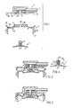
- Fig. 1 shows an exploded view of a holder consisting of three components.
- Fig. 2 shows a sectional view of a holder in idle position and
- Fig. 3 shows a sectional view of a holder in active position that is, with the holder attached to the skin.
- the various parts of the embodiment are best seen from Fig. 1.
- the diagnostic or therapeutic arrangement has a preferentially flat surface or a surface which is slightly concave with respect to the skin. Its outer form is determined by the cooperation with the other components of the holder described here.
- the diagnostically or therapeutically operative part 30 of the arrangement 1 is preferentially arranged at or near surface 4.
- the operative part 30 is connected to a recorder or to an electrical power source not shown in Figs 1-3.
- Arrangement 1 on the side opposite to surface 4 is provided with a stem 5, forming the male part of a press-stud connector that can be fastened in the female part 6 of the connector in a backpiece 3, which female part thereby penetrates a hole 18 in an intermediate element 2, which, i.a., comprises sealing ring 9.
- the male and female parts of the press-stud connector comprise a number of isolated electrical and other contacts necessary for the transmission of signals or power.
- the backpiece 3 may be advantageously made of non-conducting plastics, eventually provided with some sort of electrical shielding not shown here.
- a vacuum hose or tube communicating with a vacuum pump or a reservoir, in which the shielded electrical conductors are drawn to the female part 6.
- the diagnostic or therapeutic arrangement 1 is thus rigidly connected to the backpiece and, via the lead or bundle of conductors 7, communicates with measuring equipment or a power source of known type.
- the vacuum tube 8 is connected to a cavity in backpiece 3 and, circumferentially to the press-stud connector part 6, there are provided a number of holes 20.
- Fig. 1 When the three parts in Fig. 1 are assembled, the configuration shown in Fig. 2 is obtained.
- Fig. 1 has been provided with reference numbers, but a comparison is easy to make anyway.
- parts 1 and 2 are rotationally symmetric which simplifies manufacture but is not absolutely necessary.
- Part 2 which is made from silicone rubber or a similar material, has a relatively rigid ring portion 9 with a circumferential sealing lip 13, which in use is sealing against the skin. To start with, the function in an idle state will be described.
- a break force applied via hose 8 will cause the skin to accompany the movement until deformation is too great and the lip 13 is no longer able to provide a seal, whereupon the electrode will fall off, and the resilient flange returns to the position shown in Fig. 2, with the valve seal once again in effect.
- the surface 4 of arrangement 1 in the position shown in Fig. 3 must be inwardly drawn relative to the lip 13 on the ring 9. With a diameter of 30mm for the lip, the surface is suitably inwardly drawn to a depth of 3-4 mm.
- arrangement 1 comprising a micro electret microphone has made possible the objective recording of heart sounds. Recording of heart sounds with simultaneous recording of ECG provides valuable information in various types of heart defects.
- the position of the microphone may be easily changed until the optimal position for the registration of the respective heart sound has been found.
- a microphone amplifier can be integrated in arrangement 1 in order to further improve signal quality.
- FIG. 4 An arrangement of known type as such for the registration of acoustic signals is shown in Fig. 4.
- the sound is transferred from the skin to the diaphragm 21 and, from there, to the microphone 22.
- Conductors 23 and 24 connect the microphone with contacts 25 and 26 at the male part of the press-stud connector.
- the female connector part not shown here has been arranged to fit contacts 25 and 26 and has two conductors isolated from each other, which together constitute conductor bundle 7 in the vacuum tube to the recording instrument not shown here.
- Arrangement 1 can be easily adapted to comprise other diagnostic and therapeutic arrangements mentioned before.
- the good fixation of the holder provides for the recording of heart sounds, temperature, measurement of blood gases, etc., even in the case of physical activity, for example in examinations under physical exercise.
- the presence of dense body hair does not prevent the holder from remaining firmly seated. Because of the negative pressure being small, the holder may remain attached for a long period of time without suction marks appearing on the skin, except for a slight red ring where lip 13 abuts the skin.
- the press-stud connection between the diagnostic or therapeutic element 1 and the backpiece 3 makes the former easily exchangeable. This makes possible that new or sterilized used parts can be rapidly placed on the holder, which may be used for the next patient.
- the elastomer element 2 can be made of sterilizable material and be used repeatedly. The invention thereby is exceptionally practical and hygienic. When it is used under conditions with increased transpiration, it may be appropriate to mount in the holder some moisture- absorbing material, e.g. a disk of fibrous material, which can be inserted between the elastomer element and the backpiece, and which may be discarded after use.
Abstract
Description
- The invention relates to a holder of the kind defined in the preamble of
claim 1 for the attachment of diagnostic and therapeutic devices to the skin at a certain predetermined site of the human body. - Diagnostic and therapeutic devices intended to be attached to the human body for a longer period than a few seconds are normally kept in place by adhesive tape, by fixation with rubber bands or in a similar way. For ECG-electrodes, fixation arrangements of an essentially different kinG have been described where fixation is achieved with the aid of vacuum. The present invention relates to a holder for use for all types of diagnostic and therapeutic devices to be temporarily fixed on the skin, except for ECG-electrodes.
- Said known arrangements for fixation display various drawbacks. The method of attachment by adhesive tape is simple but does not provide for the easy displacement of the device to another site of the skin, in case it had not been put in the right place from the beginning. Moreover, adhesive tape may cause inconvenience when removed from areas with hair growth, may fall off through the effect of transpiration, or may, in the case of un- cautious handling during application, fasten in places not considered for application. With said fixation arrangements, it is moreover not easy to bring into skin contact diagnostic and therapeutic devices in a way that guarantees a constant force over time to be exerted by the device onto the skin. Keeping the force of attachment constant is important in, e.g., receiving electrical or acoustic signals through the skin.
- An ECG-electrode integrated arrangement for attachment displaying the characteristics of the preamble of
claim 1, which is thus considered to be fastened by vacuum provided through a tube, and which has a valve in closed position when the electrode is not being attached opening automatically when it is applied, and closing automatically when the electrode falls off, is known by the Austrian patent specification No. 248608. - According to en embodiment described there, a spring-biassed electrode plate with the aid of an elastic diaphragm is coupled to a surrounding sealing ring. When the electrode plate is pressed against the skin of a patient, a valve opens and vacuum is applied to a cavity extending around the electrode, delimited by the sealing ring.
- Unfortunately, it has been found that the electrode plate abuting against the skin becomes swiveling and axially movable in relation to the sealing ring, resulting in inferior skin attachment and in a varying contact between the skin and the electrode when there is movement.
- A holder integrated with an ECG-electrode. which is held in position by means of vacuum and which has a surrounding sealing ring which is relatively rigidly connected to a centrally located electrode plate, is known from the US Patent Specification No. 4 248 243. With this electrode, however, suction cannot be applied through a tube from a central vacuum source, since it lacks the self- closing valve of the Austrian patent, which valve cannot be combined with the rigid design. In addition to that, the arrangement described in the US patent specification is highly disturbing since it emits a whizzing noise arising in the ejector suction element.
- It is one aim with the present invention to provide an arrangement for holding in place, which is superior in fulfilling its purpose in that it is easier to attach, remains firmly seated, is easily transferred from one site on the skin to another, and is easily removable. These aims and advantages have been achieved according to the invention by what is stated in the characterizing part of
claim 1. Advantageous embodiments are specified in the dependent claims. - By the invention, a holder, fixed by vacuum, for diagnostic and therapeutic devices is obtained, which displays an essentially rigid connection between the portion of the diagnostic or therapeutic device attached to the skin and a surrounding sealing ring provided with a sealing lip. Suitably, the sealing lip is somewhat but not much resiliently arranged so that sealing is obtained against a moderately curved surface. The diagnostic or therapeutic device forms an integrated part of the holder attached by vacuum, and is thereby fulfilling a mechanical function as a distance-determining element (dolly element) when contact with the skin has been obtained.
- Diagnostic devices intended to be attached to the skin by means of the present vacuum-fixed holder are, for example, electrodes for electroen- caphalography (ECG), electrodes for electromyog- raphy (EMG), sensors for skin temperature, humidity, and pH, biosensors and other sensors for indirect or direct measurement of blood gases, intramuscular sensor probes for, e.g., measurement of local peripheral circulation by laser-Doppler techniques, microphones for the registration of heart sounds, etc.
- Therapeutic devices intended to be attached to the skin by means of the present vacuum-fixed holder are, e.g., electrodes for electrical stimulation of muscles, defibrillators, injectors for intramuscular administration of pharmaceuticals, electrodes for hyperthermal treatment, devices for percutaneous administration of pharmaceuticals, etc.
- In accordance with an advantageous aspect, the invention may be realized in embodiments of partially disposible sort or with easily exchangable parts which are sterilizable.
- The diagnostic or therapeutic arrangement may be rigidly or removably connected to the vacuum-fixed holder. If removably connected, the connection may advantageously be made according to the press-stud connection principle.
- The invention will now be described with reference to an exemplifying but not limiting embodiment thereof. In this context, Fig. 1 shows an exploded view of a holder consisting of three components. Fig. 2 shows a sectional view of a holder in idle position and Fig. 3 shows a sectional view of a holder in active position that is, with the holder attached to the skin.
- The various parts of the embodiment are best seen from Fig. 1. The diagnostic or therapeutic arrangement has a preferentially flat surface or a surface which is slightly concave with respect to the skin. Its outer form is determined by the cooperation with the other components of the holder described here. The diagnostically or therapeutically
operative part 30 of thearrangement 1 is preferentially arranged at or near surface 4. Theoperative part 30 is connected to a recorder or to an electrical power source not shown in Figs 1-3.Arrangement 1 on the side opposite to surface 4 is provided with astem 5, forming the male part of a press-stud connector that can be fastened in thefemale part 6 of the connector in abackpiece 3, which female part thereby penetrates ahole 18 in an intermediate element 2, which, i.a., comprises sealing ring 9. It is a resilient press-stud connector of a type in common use. Although not shown in Figs. 1-3, the male and female parts of the press-stud connector comprise a number of isolated electrical and other contacts necessary for the transmission of signals or power. Thebackpiece 3 may be advantageously made of non-conducting plastics, eventually provided with some sort of electrical shielding not shown here. Tobackpiece 3, there is connected a vacuum hose or tube communicating with a vacuum pump or a reservoir, in which the shielded electrical conductors are drawn to thefemale part 6. When the press-stud connection is made via 5,6, the diagnostic ortherapeutic arrangement 1 is thus rigidly connected to the backpiece and, via the lead or bundle ofconductors 7, communicates with measuring equipment or a power source of known type. The vacuum tube 8 is connected to a cavity inbackpiece 3 and, circumferentially to the press-stud connector part 6, there are provided a number ofholes 20. - When the three parts in Fig. 1 are assembled, the configuration shown in Fig. 2 is obtained. For the sake of clarity, only Fig. 1 has been provided with reference numbers, but a comparison is easy to make anyway. In the example shown,
parts 1 and 2 are rotationally symmetric which simplifies manufacture but is not absolutely necessary. - Part 2, which is made from silicone rubber or a similar material, has a relatively rigid ring portion 9 with a
circumferential sealing lip 13, which in use is sealing against the skin. To start with, the function in an idle state will be described. - It is obvious that the relatively flat central portion of intermediate element 2 provided with
hole 18 will abut against the sealinglip 15 inbackpiece 3. The front side of the central portion via circumferentially arrangedholes 11 communicates with the rear side of intermediate element 2, on which there is arranged another sealinglip 14. This lip will abut against the rear side of the diagnostic ortherapeutic arrangement 1, and bothlip 14 andlip 15 will seal off a volume around the central portion ofpart 1 being put under vacuum, whereby a certain bending of the central portion of intermediate element 2 occurs to which also contributes thatflange 17 on the intermediate part 2 is elastically abuting againstlip 16 onbackpiece 3. With the configuration in Fig. 2, notwithstanding unsignificant leakage, only said volume around the central part ofarrangement 1 will be put under vacuum. - When the electrode, being in a configuration according to Fig. 2, is attached to a skin surface, the following will occur. When the circumferential lip is pressed against the skin, the force will affect
flange 17 via the relatively rigid ring 9, which is resiliently deformed, whereby the central part of intermediate element 2 is more excessively deformed andlip 14 eases away from the rear side ofarrangement 1. The space between the skin and the intermediate element 2 is placed in communication with the vacuum source, and since the intermediate element 2 is provided withholes 12 in its peripheral part, all spaces will be placed under vacuum, thesealing lips backpiece 3 and the skin. The configuration illustrated in Fig. 3 is thereby obtained. - It will be clear from Fig. 3 that the
backpiece 3 and the ring 9 now function as an interlocking composite assembly. Although the ring 9 is urged outwardly, away from thebackpiece 3 by an elastic deformation force acting through theflange 17, this force is quite insignificant in comparison with the pneumatic forces. The vacuum used need not reach more than 0.1 kg/cm2. The air pressure then exerts against the skin a force which corresponds substantially to the force exerted by the surface embraced bylip 13. This force is counter-acted by the resistance normally offered by the skin, the greater part of which resistance is exerted on the under-surface 4 ofarrangement 1, thereby to achieve particularly good contact. Due to the deformation of the skin, there is also obtained a certain shape-conforming effect which prevents slipping. A break force applied via hose 8 will cause the skin to accompany the movement until deformation is too great and thelip 13 is no longer able to provide a seal, whereupon the electrode will fall off, and the resilient flange returns to the position shown in Fig. 2, with the valve seal once again in effect. - Thus, in order to obtain good functioning, the surface 4 of
arrangement 1 in the position shown in Fig. 3 must be inwardly drawn relative to thelip 13 on the ring 9. With a diameter of 30mm for the lip, the surface is suitably inwardly drawn to a depth of 3-4 mm. - The described embodiment has been shown to function extremely well. For example,
arrangement 1 comprising a micro electret microphone has made possible the objective recording of heart sounds. Recording of heart sounds with simultaneous recording of ECG provides valuable information in various types of heart defects. The position of the microphone may be easily changed until the optimal position for the registration of the respective heart sound has been found. A microphone amplifier can be integrated inarrangement 1 in order to further improve signal quality. - An arrangement of known type as such for the registration of acoustic signals is shown in Fig. 4. The sound is transferred from the skin to the
diaphragm 21 and, from there, to themicrophone 22.Conductors contacts contacts conductor bundle 7 in the vacuum tube to the recording instrument not shown here. -
Arrangement 1 can be easily adapted to comprise other diagnostic and therapeutic arrangements mentioned before. - The good fixation of the holder provides for the recording of heart sounds, temperature, measurement of blood gases, etc., even in the case of physical activity, for example in examinations under physical exercise. The presence of dense body hair does not prevent the holder from remaining firmly seated. Because of the negative pressure being small, the holder may remain attached for a long period of time without suction marks appearing on the skin, except for a slight red ring where
lip 13 abuts the skin. - The press-stud connection between the diagnostic or
therapeutic element 1 and thebackpiece 3 makes the former easily exchangeable. This makes possible that new or sterilized used parts can be rapidly placed on the holder, which may be used for the next patient. The elastomer element 2 can be made of sterilizable material and be used repeatedly. The invention thereby is exceptionally practical and hygienic. When it is used under conditions with increased transpiration, it may be appropriate to mount in the holder some moisture- absorbing material, e.g. a disk of fibrous material, which can be inserted between the elastomer element and the backpiece, and which may be discarded after use.
Claims (16)
Applications Claiming Priority (2)
| Application Number | Priority Date | Filing Date | Title |
|---|---|---|---|
| SE8502048 | 1985-04-26 | ||
| SE8502048A SE8502048D0 (en) | 1985-04-26 | 1985-04-26 | VACUUM FIXED HALLS FOR MEDICAL USE |
Publications (2)
| Publication Number | Publication Date |
|---|---|
| EP0199694A2 true EP0199694A2 (en) | 1986-10-29 |
| EP0199694A3 EP0199694A3 (en) | 1988-09-14 |
Family
ID=20359991
Family Applications (1)
| Application Number | Title | Priority Date | Filing Date |
|---|---|---|---|
| EP86850130A Withdrawn EP0199694A3 (en) | 1985-04-26 | 1986-04-15 | Holder for medical use fixed by vacuum |
Country Status (7)
| Country | Link |
|---|---|
| US (1) | US4736749A (en) |
| EP (1) | EP0199694A3 (en) |
| JP (1) | JPS61249439A (en) |
| AU (1) | AU582429B2 (en) |
| DK (1) | DK158586A (en) |
| FI (1) | FI861399A (en) |
| SE (1) | SE8502048D0 (en) |
Cited By (4)
| Publication number | Priority date | Publication date | Assignee | Title |
|---|---|---|---|---|
| EP0289905A1 (en) * | 1987-05-08 | 1988-11-09 | Siemens Aktiengesellschaft | Suction electrode |
| EP0352596A1 (en) * | 1988-07-29 | 1990-01-31 | Siemens Aktiengesellschaft | Suction electrodes for electro-medical apparatus |
| US8852181B2 (en) | 2003-03-27 | 2014-10-07 | Terumo Kabushiki Kaisha | Energy based devices and methods for treatment of anatomic tissue defects |
| US9468437B2 (en) | 1996-08-22 | 2016-10-18 | The Trustees Of Columbia University In The City Of New York | Endovascular flexible stapling device |
Families Citing this family (162)
| Publication number | Priority date | Publication date | Assignee | Title |
|---|---|---|---|---|
| JPS646960U (en) * | 1987-06-30 | 1989-01-17 | ||
| JPS6431754U (en) * | 1987-08-17 | 1989-02-27 | ||
| JPH0614758Y2 (en) * | 1988-04-02 | 1994-04-20 | 株式会社アドバンス | Biomedical electrode |
| US5089015A (en) * | 1989-11-28 | 1992-02-18 | Promedica International | Method for implanting unstented xenografts and allografts |
| GB9008764D0 (en) * | 1990-04-19 | 1990-06-13 | Egnell Ameda Ltd | A resilient suction cup |
| SE500187C2 (en) * | 1991-06-07 | 1994-05-02 | Humanteknik Ab | Method for transporting liquid and pumping device for carrying out the process |
| DK0626820T3 (en) * | 1992-02-20 | 2000-04-25 | Quickels Systems Ab | Device for attaching an object to a surface by vacuum |
| US6161543A (en) | 1993-02-22 | 2000-12-19 | Epicor, Inc. | Methods of epicardial ablation for creating a lesion around the pulmonary veins |
| US6494211B1 (en) | 1993-02-22 | 2002-12-17 | Hearport, Inc. | Device and methods for port-access multivessel coronary artery bypass surgery |
| SE503420C2 (en) * | 1993-11-16 | 1996-06-10 | Humanteknik Ab | Absorbent unit for use in a biomedical electrode |
| US5833622A (en) * | 1994-04-04 | 1998-11-10 | Graphic Controls Corporation | Non-invasive fetal probe having improved mechanical and electrical properties |
| US5807243A (en) | 1994-08-31 | 1998-09-15 | Heartport, Inc. | Method for isolating a surgical site |
| US6409722B1 (en) * | 1998-07-07 | 2002-06-25 | Medtronic, Inc. | Apparatus and method for creating, maintaining, and controlling a virtual electrode used for the ablation of tissue |
| US5897553A (en) | 1995-11-02 | 1999-04-27 | Medtronic, Inc. | Ball point fluid-assisted electrocautery device |
| US5904697A (en) | 1995-02-24 | 1999-05-18 | Heartport, Inc. | Devices and methods for performing a vascular anastomosis |
| US5888247A (en) * | 1995-04-10 | 1999-03-30 | Cardiothoracic Systems, Inc | Method for coronary artery bypass |
| US7445594B1 (en) | 1995-09-20 | 2008-11-04 | Medtronic, Inc. | Method and apparatus for temporarily immobilizing a local area of tissue |
| US5836311A (en) | 1995-09-20 | 1998-11-17 | Medtronic, Inc. | Method and apparatus for temporarily immobilizing a local area of tissue |
| US5913876A (en) | 1996-02-20 | 1999-06-22 | Cardiothoracic Systems, Inc. | Method and apparatus for using vagus nerve stimulation in surgery |
| CA2197614C (en) * | 1996-02-20 | 2002-07-02 | Charles S. Taylor | Surgical instruments and procedures for stabilizing the beating heart during coronary artery bypass graft surgery |
| US5894843A (en) | 1996-02-20 | 1999-04-20 | Cardiothoracic Systems, Inc. | Surgical method for stabilizing the beating heart during coronary artery bypass graft surgery |
| US6852075B1 (en) | 1996-02-20 | 2005-02-08 | Cardiothoracic Systems, Inc. | Surgical devices for imposing a negative pressure to stabilize cardiac tissue during surgery |
| US6290644B1 (en) | 1996-02-20 | 2001-09-18 | Cardiothoracic Systems, Inc. | Surgical instruments and procedures for stabilizing a localized portion of a beating heart |
| NL1003024C2 (en) * | 1996-05-03 | 1997-11-06 | Tjong Hauw Sie | Stimulus conduction blocking instrument. |
| US7052493B2 (en) | 1996-10-22 | 2006-05-30 | Epicor Medical, Inc. | Methods and devices for ablation |
| US6805128B1 (en) | 1996-10-22 | 2004-10-19 | Epicor Medical, Inc. | Apparatus and method for ablating tissue |
| US6719755B2 (en) * | 1996-10-22 | 2004-04-13 | Epicor Medical, Inc. | Methods and devices for ablation |
| US6237605B1 (en) | 1996-10-22 | 2001-05-29 | Epicor, Inc. | Methods of epicardial ablation |
| US6840936B2 (en) | 1996-10-22 | 2005-01-11 | Epicor Medical, Inc. | Methods and devices for ablation |
| US6311692B1 (en) | 1996-10-22 | 2001-11-06 | Epicor, Inc. | Apparatus and method for diagnosis and therapy of electrophysiological disease |
| JP3036686B2 (en) * | 1997-02-27 | 2000-04-24 | 政夫 高橋 | Hemostatic holding device for vascular anastomosis used for coronary artery bypass surgery |
| US6096037A (en) | 1997-07-29 | 2000-08-01 | Medtronic, Inc. | Tissue sealing electrosurgery device and methods of sealing tissue |
| US5924985A (en) * | 1997-07-29 | 1999-07-20 | Ohmeda Inc. | Patient probe disconnect alarm |
| US6390976B1 (en) * | 1997-09-17 | 2002-05-21 | Origin Medsystems, Inc. | System to permit offpump beating heart coronary bypass surgery |
| US6338712B2 (en) | 1997-09-17 | 2002-01-15 | Origin Medsystems, Inc. | Device to permit offpump beating heart coronary bypass surgery |
| US6969349B1 (en) * | 1997-09-17 | 2005-11-29 | Origin Medsystem, Inc. | Device to permit offpump beating heart coronary bypass surgery |
| US8709007B2 (en) | 1997-10-15 | 2014-04-29 | St. Jude Medical, Atrial Fibrillation Division, Inc. | Devices and methods for ablating cardiac tissue |
| US6231585B1 (en) | 1997-11-20 | 2001-05-15 | Medivas, Llc | Device for stabilizing a treatment site and method of use |
| US6706039B2 (en) * | 1998-07-07 | 2004-03-16 | Medtronic, Inc. | Method and apparatus for creating a bi-polar virtual electrode used for the ablation of tissue |
| US6537248B2 (en) * | 1998-07-07 | 2003-03-25 | Medtronic, Inc. | Helical needle apparatus for creating a virtual electrode used for the ablation of tissue |
| US6345192B1 (en) * | 1998-09-08 | 2002-02-05 | Venturi Medical Systems, Llc | Electrode structure for electric contactor |
| BR9913759A (en) * | 1998-09-15 | 2001-06-12 | Medtronic Inc | System to temporarily immobilize an area of tissue, and system to stabilize tissue |
| US8308719B2 (en) * | 1998-09-21 | 2012-11-13 | St. Jude Medical, Atrial Fibrillation Division, Inc. | Apparatus and method for ablating tissue |
| US6245062B1 (en) * | 1998-10-23 | 2001-06-12 | Afx, Inc. | Directional reflector shield assembly for a microwave ablation instrument |
| US6231506B1 (en) | 1999-05-04 | 2001-05-15 | Cardiothoracic Systems, Inc. | Method and apparatus for creating a working opening through an incision |
| US6283912B1 (en) | 1999-05-04 | 2001-09-04 | Cardiothoracic Systems, Inc. | Surgical retractor platform blade apparatus |
| US6626830B1 (en) * | 1999-05-04 | 2003-09-30 | Cardiothoracic Systems, Inc. | Methods and devices for improved tissue stabilization |
| AU4701800A (en) * | 1999-05-04 | 2000-11-17 | Cardiothoracic Systems, Inc. | Surgical instruments for accessing and stabilizing a localized portion of a beating heart |
| US20070282324A1 (en) * | 1999-07-19 | 2007-12-06 | Matthias Vaska | Apparatus and method for diagnosis and therapy of electrophysiological disease |
| EP1207788A4 (en) * | 1999-07-19 | 2009-12-09 | St Jude Medical Atrial Fibrill | Apparatus and method for ablating tissue |
| US6511416B1 (en) | 1999-08-03 | 2003-01-28 | Cardiothoracic Systems, Inc. | Tissue stabilizer and methods of use |
| US6773418B1 (en) | 1999-08-18 | 2004-08-10 | Iotek, Inc. | Device and method for delivery of agents to the female reproductive tract |
| US6406424B1 (en) * | 1999-09-16 | 2002-06-18 | Williamson, Iv Warren P. | Tissue stabilizer having an articulating lift element |
| US8241274B2 (en) | 2000-01-19 | 2012-08-14 | Medtronic, Inc. | Method for guiding a medical device |
| US8221402B2 (en) * | 2000-01-19 | 2012-07-17 | Medtronic, Inc. | Method for guiding a medical device |
| US7706882B2 (en) * | 2000-01-19 | 2010-04-27 | Medtronic, Inc. | Methods of using high intensity focused ultrasound to form an ablated tissue area |
| US7338434B1 (en) | 2002-08-21 | 2008-03-04 | Medtronic, Inc. | Method and system for organ positioning and stabilization |
| US6692450B1 (en) | 2000-01-19 | 2004-02-17 | Medtronic Xomed, Inc. | Focused ultrasound ablation devices having selectively actuatable ultrasound emitting elements and methods of using the same |
| US6447443B1 (en) | 2001-01-13 | 2002-09-10 | Medtronic, Inc. | Method for organ positioning and stabilization |
| US6595934B1 (en) * | 2000-01-19 | 2003-07-22 | Medtronic Xomed, Inc. | Methods of skin rejuvenation using high intensity focused ultrasound to form an ablated tissue area containing a plurality of lesions |
| US6663622B1 (en) * | 2000-02-11 | 2003-12-16 | Iotek, Inc. | Surgical devices and methods for use in tissue ablation procedures |
| US6728565B2 (en) * | 2000-02-25 | 2004-04-27 | Scimed Life Systems, Inc. | Diagnostic catheter using a vacuum for tissue positioning |
| US8048070B2 (en) | 2000-03-06 | 2011-11-01 | Salient Surgical Technologies, Inc. | Fluid-assisted medical devices, systems and methods |
| WO2001082812A1 (en) | 2000-04-27 | 2001-11-08 | Medtronic, Inc. | Vibration sensitive ablation apparatus and method |
| US6488680B1 (en) | 2000-04-27 | 2002-12-03 | Medtronic, Inc. | Variable length electrodes for delivery of irrigated ablation |
| AU2001249874A1 (en) * | 2000-04-27 | 2001-11-12 | Medtronic, Inc. | System and method for assessing transmurality of ablation lesions |
| US6514250B1 (en) | 2000-04-27 | 2003-02-04 | Medtronic, Inc. | Suction stabilized epicardial ablation devices |
| US6926669B1 (en) | 2000-10-10 | 2005-08-09 | Medtronic, Inc. | Heart wall ablation/mapping catheter and method |
| FR2815407B1 (en) * | 2000-10-13 | 2003-01-24 | Seb Sa | NON-INVASIVE ELECTRONIC THERMOMETER |
| US20040138621A1 (en) * | 2003-01-14 | 2004-07-15 | Jahns Scott E. | Devices and methods for interstitial injection of biologic agents into tissue |
| US6676597B2 (en) | 2001-01-13 | 2004-01-13 | Medtronic, Inc. | Method and device for organ positioning |
| US7628780B2 (en) | 2001-01-13 | 2009-12-08 | Medtronic, Inc. | Devices and methods for interstitial injection of biologic agents into tissue |
| US7740623B2 (en) | 2001-01-13 | 2010-06-22 | Medtronic, Inc. | Devices and methods for interstitial injection of biologic agents into tissue |
| US6758808B2 (en) | 2001-01-24 | 2004-07-06 | Cardiothoracic System, Inc. | Surgical instruments for stabilizing a localized portion of a beating heart |
| US7250048B2 (en) | 2001-04-26 | 2007-07-31 | Medtronic, Inc. | Ablation system and method of use |
| US6663627B2 (en) | 2001-04-26 | 2003-12-16 | Medtronic, Inc. | Ablation system and method of use |
| US7959626B2 (en) * | 2001-04-26 | 2011-06-14 | Medtronic, Inc. | Transmural ablation systems and methods |
| US6807968B2 (en) | 2001-04-26 | 2004-10-26 | Medtronic, Inc. | Method and system for treatment of atrial tachyarrhythmias |
| US6648883B2 (en) * | 2001-04-26 | 2003-11-18 | Medtronic, Inc. | Ablation system and method of use |
| US6699240B2 (en) * | 2001-04-26 | 2004-03-02 | Medtronic, Inc. | Method and apparatus for tissue ablation |
| EP1435867B1 (en) | 2001-09-05 | 2010-11-17 | Salient Surgical Technologies, Inc. | Fluid-assisted medical devices and systems |
| US6656175B2 (en) * | 2001-12-11 | 2003-12-02 | Medtronic, Inc. | Method and system for treatment of atrial tachyarrhythmias |
| US20030139645A1 (en) * | 2002-01-23 | 2003-07-24 | Adelman Thomas G. | Rotational freedom for a body organ |
| EP1467658A1 (en) * | 2002-01-23 | 2004-10-20 | Iotek, Inc. | Devices for holding a body organ |
| US7967816B2 (en) | 2002-01-25 | 2011-06-28 | Medtronic, Inc. | Fluid-assisted electrosurgical instrument with shapeable electrode |
| US6827715B2 (en) * | 2002-01-25 | 2004-12-07 | Medtronic, Inc. | System and method of performing an electrosurgical procedure |
| US20080275439A1 (en) * | 2002-01-25 | 2008-11-06 | David Francischelli | Cardiac ablation and electrical interface system and instrument |
| US7054677B2 (en) * | 2002-04-16 | 2006-05-30 | Venturi Medical Systems | Venturi ECG electrode system |
| US7294143B2 (en) * | 2002-05-16 | 2007-11-13 | Medtronic, Inc. | Device and method for ablation of cardiac tissue |
| US7118566B2 (en) * | 2002-05-16 | 2006-10-10 | Medtronic, Inc. | Device and method for needle-less interstitial injection of fluid for ablation of cardiac tissue |
| US7494460B2 (en) | 2002-08-21 | 2009-02-24 | Medtronic, Inc. | Methods and apparatus providing suction-assisted tissue engagement through a minimally invasive incision |
| US7931590B2 (en) | 2002-10-29 | 2011-04-26 | Maquet Cardiovascular Llc | Tissue stabilizer and methods of using the same |
| US7083620B2 (en) * | 2002-10-30 | 2006-08-01 | Medtronic, Inc. | Electrosurgical hemostat |
| TW200505626A (en) * | 2003-01-29 | 2005-02-16 | Mitsuboshi Diamond Ind Co Ltd | Vacuum suction head |
| US20040186467A1 (en) * | 2003-03-21 | 2004-09-23 | Swanson David K. | Apparatus for maintaining contact between diagnostic and therapeutic elements and tissue and systems including the same |
| US7497857B2 (en) * | 2003-04-29 | 2009-03-03 | Medtronic, Inc. | Endocardial dispersive electrode for use with a monopolar RF ablation pen |
| US7479104B2 (en) | 2003-07-08 | 2009-01-20 | Maquet Cardiovascular, Llc | Organ manipulator apparatus |
| US20050107831A1 (en) * | 2003-11-18 | 2005-05-19 | Encore Medical Asset Corporation | System for therapeutic application of energy |
| US7608072B2 (en) | 2003-12-02 | 2009-10-27 | Boston Scientific Scimed, Inc. | Surgical methods and apparatus for maintaining contact between tissue and electrophysiology elements and confirming whether a therapeutic lesion has been formed |
| US8055357B2 (en) * | 2003-12-02 | 2011-11-08 | Boston Scientific Scimed, Inc. | Self-anchoring surgical methods and apparatus for stimulating tissue |
| US8052676B2 (en) * | 2003-12-02 | 2011-11-08 | Boston Scientific Scimed, Inc. | Surgical methods and apparatus for stimulating tissue |
| US20050148824A1 (en) * | 2003-12-30 | 2005-07-07 | Morejohn Dwight P. | Transabdominal surgery system |
| US7179224B2 (en) * | 2003-12-30 | 2007-02-20 | Cardiothoracic Systems, Inc. | Organ manipulator and positioner and methods of using the same |
| US7371233B2 (en) * | 2004-02-19 | 2008-05-13 | Boston Scientific Scimed, Inc. | Cooled probes and apparatus for maintaining contact between cooled probes and tissue |
| US7399272B2 (en) | 2004-03-24 | 2008-07-15 | Medtronic, Inc. | Methods and apparatus providing suction-assisted tissue engagement |
| US8333764B2 (en) * | 2004-05-12 | 2012-12-18 | Medtronic, Inc. | Device and method for determining tissue thickness and creating cardiac ablation lesions |
| ES2308505T3 (en) | 2004-05-14 | 2008-12-01 | Medtronic, Inc. | ULTRASONIC ENERGY USE SYSTEM FOCUSED ON HIGH INTENS IDAD TO FORM A CUTTED FABRIC AREA. |
| DE602005021096D1 (en) * | 2004-06-02 | 2010-06-17 | Medtronic Inc | COMPOUND BIPOLAR ABLATION DEVICE |
| WO2005120377A1 (en) * | 2004-06-02 | 2005-12-22 | Medtronic, Inc. | Clamping ablation tool |
| EP1750608B1 (en) * | 2004-06-02 | 2012-10-03 | Medtronic, Inc. | Ablation device with jaws |
| EP1750607A2 (en) * | 2004-06-02 | 2007-02-14 | Medtronic, Inc. | Loop ablation apparatus and method |
| US8409219B2 (en) * | 2004-06-18 | 2013-04-02 | Medtronic, Inc. | Method and system for placement of electrical lead inside heart |
| EP1768575B1 (en) * | 2004-06-18 | 2019-01-16 | Medtronic, Inc. | Devices for occlusion of an atrial appendage |
| US8926635B2 (en) * | 2004-06-18 | 2015-01-06 | Medtronic, Inc. | Methods and devices for occlusion of an atrial appendage |
| US8663245B2 (en) | 2004-06-18 | 2014-03-04 | Medtronic, Inc. | Device for occlusion of a left atrial appendage |
| US7593777B2 (en) * | 2004-10-26 | 2009-09-22 | Medtronic, Inc. | Fixation of a medical implant to the exterior of a body organ |
| US20060095079A1 (en) * | 2004-10-29 | 2006-05-04 | Gerber Martin T | Sub-mucosal medical device implantation |
| JP4491340B2 (en) * | 2004-12-28 | 2010-06-30 | 株式会社コガネイ | Transport device |
| US7455669B2 (en) * | 2005-03-08 | 2008-11-25 | Boston Scientific Scimed, Inc. | Finger mountable lesion formation devices and methods |
| US8083664B2 (en) | 2005-05-25 | 2011-12-27 | Maquet Cardiovascular Llc | Surgical stabilizers and methods for use in reduced-access surgical sites |
| US8932208B2 (en) | 2005-05-26 | 2015-01-13 | Maquet Cardiovascular Llc | Apparatus and methods for performing minimally-invasive surgical procedures |
| US8016822B2 (en) * | 2005-05-28 | 2011-09-13 | Boston Scientific Scimed, Inc. | Fluid injecting devices and methods and apparatus for maintaining contact between fluid injecting devices and tissue |
| US20070142738A1 (en) * | 2005-12-16 | 2007-06-21 | Chin-Yeh Hung | Dynamic heart rate monitor |
| US7794387B2 (en) | 2006-04-26 | 2010-09-14 | Medtronic, Inc. | Methods and devices for stabilizing tissue |
| US20080039746A1 (en) * | 2006-05-25 | 2008-02-14 | Medtronic, Inc. | Methods of using high intensity focused ultrasound to form an ablated tissue area containing a plurality of lesions |
| CN101528136A (en) | 2006-08-07 | 2009-09-09 | 迪普布雷兹有限公司 | Microphone matrix for recording body sounds |
| US20080200777A1 (en) * | 2006-10-31 | 2008-08-21 | Nathalie Issachar | Acoustic systems and methods for evaluating skin texture |
| US8301265B2 (en) | 2007-09-10 | 2012-10-30 | Medtronic, Inc. | Selective depth electrode deployment for electrical stimulation |
| WO2009045265A1 (en) | 2007-10-05 | 2009-04-09 | Maquet Cardiovascular, Llc | Devices and methods for minimally-invasive surgical procedures |
| US8353907B2 (en) * | 2007-12-21 | 2013-01-15 | Atricure, Inc. | Ablation device with internally cooled electrodes |
| US8998892B2 (en) | 2007-12-21 | 2015-04-07 | Atricure, Inc. | Ablation device with cooled electrodes and methods of use |
| WO2009086448A1 (en) | 2007-12-28 | 2009-07-09 | Salient Surgical Technologies, Inc. | Fluid-assisted electrosurgical devices, methods and systems |
| JP5307124B2 (en) * | 2008-04-10 | 2013-10-02 | 正樹 西岡 | Negative skin pressure maintaining device |
| WO2009140359A2 (en) * | 2008-05-13 | 2009-11-19 | Medtronic, Inc. | Tissue lesion evaluation |
| US9254168B2 (en) | 2009-02-02 | 2016-02-09 | Medtronic Advanced Energy Llc | Electro-thermotherapy of tissue using penetrating microelectrode array |
| JP5592409B2 (en) | 2009-02-23 | 2014-09-17 | サリエント・サージカル・テクノロジーズ・インコーポレーテッド | Fluid-assisted electrosurgical device and method of use thereof |
| JP2013503723A (en) | 2009-09-08 | 2013-02-04 | サリエント・サージカル・テクノロジーズ・インコーポレーテッド | Cartridge assembly for electrosurgical devices, electrosurgical units, and methods of use thereof |
| US9022998B2 (en) | 2010-02-26 | 2015-05-05 | Maquet Cardiovascular Llc | Blower instrument, apparatus and methods of using |
| WO2011107309A1 (en) * | 2010-03-05 | 2011-09-09 | Siemens Aktiengesellschaft | A sensor device and a method for using the sensor device |
| WO2011112991A1 (en) | 2010-03-11 | 2011-09-15 | Salient Surgical Technologies, Inc. | Bipolar electrosurgical cutter with position insensitive return electrode contact |
| US20110295249A1 (en) * | 2010-05-28 | 2011-12-01 | Salient Surgical Technologies, Inc. | Fluid-Assisted Electrosurgical Devices, and Methods of Manufacture Thereof |
| WO2011159733A1 (en) | 2010-06-14 | 2011-12-22 | Maquet Cardiovascular Llc | Surgical instruments, systems and methods of use |
| US9138289B2 (en) | 2010-06-28 | 2015-09-22 | Medtronic Advanced Energy Llc | Electrode sheath for electrosurgical device |
| US8906012B2 (en) | 2010-06-30 | 2014-12-09 | Medtronic Advanced Energy Llc | Electrosurgical devices with wire electrode |
| US8920417B2 (en) | 2010-06-30 | 2014-12-30 | Medtronic Advanced Energy Llc | Electrosurgical devices and methods of use thereof |
| US9023040B2 (en) | 2010-10-26 | 2015-05-05 | Medtronic Advanced Energy Llc | Electrosurgical cutting devices |
| US9427281B2 (en) | 2011-03-11 | 2016-08-30 | Medtronic Advanced Energy Llc | Bronchoscope-compatible catheter provided with electrosurgical device |
| US9750565B2 (en) | 2011-09-30 | 2017-09-05 | Medtronic Advanced Energy Llc | Electrosurgical balloons |
| US8870864B2 (en) | 2011-10-28 | 2014-10-28 | Medtronic Advanced Energy Llc | Single instrument electrosurgery apparatus and its method of use |
| TWI542456B (en) * | 2012-09-20 | 2016-07-21 | 鴻海精密工業股份有限公司 | Suction device for sucking element |
| US10631914B2 (en) | 2013-09-30 | 2020-04-28 | Covidien Lp | Bipolar electrosurgical instrument with movable electrode and related systems and methods |
| US9974599B2 (en) | 2014-08-15 | 2018-05-22 | Medtronic Ps Medical, Inc. | Multipurpose electrosurgical device |
| US9956029B2 (en) | 2014-10-31 | 2018-05-01 | Medtronic Advanced Energy Llc | Telescoping device with saline irrigation line |
| DE102015109442A1 (en) * | 2015-06-12 | 2016-12-15 | Peter Dörner | Human or veterinary diagnostic structure-borne sound pickup |
| US11389227B2 (en) | 2015-08-20 | 2022-07-19 | Medtronic Advanced Energy Llc | Electrosurgical device with multivariate control |
| US11051875B2 (en) | 2015-08-24 | 2021-07-06 | Medtronic Advanced Energy Llc | Multipurpose electrosurgical device |
| US10716612B2 (en) | 2015-12-18 | 2020-07-21 | Medtronic Advanced Energy Llc | Electrosurgical device with multiple monopolar electrode assembly |
| US20170209097A1 (en) * | 2016-01-21 | 2017-07-27 | King's Metal Fiber Technologies Co., Ltd. | Suction-attachment structure |
| KR102627434B1 (en) * | 2016-08-08 | 2024-01-18 | 주식회사 엘지생활건강 | Suction microneedle |
| WO2018089789A1 (en) | 2016-11-10 | 2018-05-17 | The Research Foundation For The State University Of New York | System, method and biomarkers for airway obstruction |
| CN107088065B (en) * | 2017-05-03 | 2021-01-29 | 京东方科技集团股份有限公司 | Brain electricity electrode |
| US10194975B1 (en) | 2017-07-11 | 2019-02-05 | Medtronic Advanced Energy, Llc | Illuminated and isolated electrosurgical apparatus |
Citations (8)
| Publication number | Priority date | Publication date | Assignee | Title |
|---|---|---|---|---|
| SU171966A1 (en) * | А. М. Рыбаков | ELECTRIC SCREEN | ||
| FR1139191A (en) * | 1955-01-17 | 1957-06-26 | Ateliers Mecaniques De Pont Su | Electrode device for massage and electrotherapy |
| FR1535432A (en) * | 1964-04-16 | 1968-08-09 | examination or biological treatment electrodes | |
| FR2178223A1 (en) * | 1972-03-27 | 1973-11-09 | Rose Ewald | |
| US3918434A (en) * | 1972-11-15 | 1975-11-11 | Eschweiler & Co | Method and apparatus for determining the perfusion efficiency factor of animal tissue |
| DE2548805A1 (en) * | 1975-10-31 | 1977-05-05 | Bosch Gmbh Robert | Suction electrode cup for medical use - has electrode mounted to move between rest and active position within cup for ECG or similar skin application purpose |
| US4380240A (en) * | 1977-06-28 | 1983-04-19 | Duke University, Inc. | Apparatus for monitoring metabolism in body organs |
| EP0143761A1 (en) * | 1983-10-28 | 1985-06-05 | Astra-Tech Aktiebolag | Electrode, fixed and stabilised by vacuum |
Family Cites Families (11)
| Publication number | Priority date | Publication date | Assignee | Title |
|---|---|---|---|---|
| US2660175A (en) * | 1951-08-10 | 1953-11-24 | Clyde E Thrasher | Electrocardiograph electrode |
| DE1108820B (en) * | 1959-10-16 | 1961-06-15 | Muenchener Elektro Physikalisc | Vacuum adhesive electrode for electromedical purposes |
| GB1128329A (en) * | 1964-12-23 | 1968-09-25 | Nat Res Dev | Electrodes for making electrical contact to the living body of a mammal |
| US3490442A (en) * | 1966-02-09 | 1970-01-20 | Hellige & Co Gmbh F | Electrode with contact-forming suction cup means |
| DE1939523B1 (en) * | 1969-08-02 | 1971-02-04 | Niess Ingeborg Elektromedizin | Suction electrode device for electrical medical devices |
| SU639524A1 (en) * | 1975-06-23 | 1978-12-30 | Рижский Ордена Трудового Красного Знамени Политехнический Институт | Suction electrode for surface removal of bioelectric potential |
| US4082086A (en) * | 1976-12-13 | 1978-04-04 | M I Systems, Inc. | Ecg monitoring pad |
| ZA803166B (en) * | 1979-06-15 | 1981-05-27 | Ndm Corp | Capacitively coupled indifferent electrode |
| US4369793A (en) * | 1980-08-18 | 1983-01-25 | Staver Peter J | Medical instrumentation electrode apparatus |
| US4490003A (en) * | 1982-01-11 | 1984-12-25 | C. R. Bard, Inc. | Electrical connector |
| DE3300765C1 (en) * | 1983-01-12 | 1983-10-20 | Ingeborg Nieß Elektromedizinische Apparate, 7906 Blaustein | Electrode device for the reduction of electro-physiological voltages |
-
1985
- 1985-04-26 SE SE8502048A patent/SE8502048D0/en unknown
-
1986
- 1986-04-01 FI FI861399A patent/FI861399A/en not_active Application Discontinuation
- 1986-04-04 US US06/849,482 patent/US4736749A/en not_active Expired - Fee Related
- 1986-04-08 DK DK158586A patent/DK158586A/en not_active IP Right Cessation
- 1986-04-09 AU AU55773/86A patent/AU582429B2/en not_active Ceased
- 1986-04-15 EP EP86850130A patent/EP0199694A3/en not_active Withdrawn
- 1986-04-25 JP JP61094975A patent/JPS61249439A/en active Pending
Patent Citations (8)
| Publication number | Priority date | Publication date | Assignee | Title |
|---|---|---|---|---|
| SU171966A1 (en) * | А. М. Рыбаков | ELECTRIC SCREEN | ||
| FR1139191A (en) * | 1955-01-17 | 1957-06-26 | Ateliers Mecaniques De Pont Su | Electrode device for massage and electrotherapy |
| FR1535432A (en) * | 1964-04-16 | 1968-08-09 | examination or biological treatment electrodes | |
| FR2178223A1 (en) * | 1972-03-27 | 1973-11-09 | Rose Ewald | |
| US3918434A (en) * | 1972-11-15 | 1975-11-11 | Eschweiler & Co | Method and apparatus for determining the perfusion efficiency factor of animal tissue |
| DE2548805A1 (en) * | 1975-10-31 | 1977-05-05 | Bosch Gmbh Robert | Suction electrode cup for medical use - has electrode mounted to move between rest and active position within cup for ECG or similar skin application purpose |
| US4380240A (en) * | 1977-06-28 | 1983-04-19 | Duke University, Inc. | Apparatus for monitoring metabolism in body organs |
| EP0143761A1 (en) * | 1983-10-28 | 1985-06-05 | Astra-Tech Aktiebolag | Electrode, fixed and stabilised by vacuum |
Non-Patent Citations (1)
| Title |
|---|
| SOVIET INVENTIONS ILLUSTRATED, Section Mechanical and General, February 1966, Derwent Publications Ltd, London, GB; & SU-A-171 966 (A.M.RYBAKOV) 22-07-1965 * |
Cited By (4)
| Publication number | Priority date | Publication date | Assignee | Title |
|---|---|---|---|---|
| EP0289905A1 (en) * | 1987-05-08 | 1988-11-09 | Siemens Aktiengesellschaft | Suction electrode |
| EP0352596A1 (en) * | 1988-07-29 | 1990-01-31 | Siemens Aktiengesellschaft | Suction electrodes for electro-medical apparatus |
| US9468437B2 (en) | 1996-08-22 | 2016-10-18 | The Trustees Of Columbia University In The City Of New York | Endovascular flexible stapling device |
| US8852181B2 (en) | 2003-03-27 | 2014-10-07 | Terumo Kabushiki Kaisha | Energy based devices and methods for treatment of anatomic tissue defects |
Also Published As
| Publication number | Publication date |
|---|---|
| AU5577386A (en) | 1986-10-30 |
| FI861399A (en) | 1986-10-27 |
| FI861399A0 (en) | 1986-04-01 |
| US4736749A (en) | 1988-04-12 |
| AU582429B2 (en) | 1989-03-23 |
| SE8502048D0 (en) | 1985-04-26 |
| EP0199694A3 (en) | 1988-09-14 |
| DK158586A (en) | 1986-10-27 |
| JPS61249439A (en) | 1986-11-06 |
| DK158586D0 (en) | 1986-04-08 |
Similar Documents
| Publication | Publication Date | Title |
|---|---|---|
| EP0199694A2 (en) | Holder for medical use fixed by vacuum | |
| EP0143761B1 (en) | Electrode, fixed and stabilised by vacuum | |
| US4476872A (en) | Esophageal probe with disposable cover | |
| US4834110A (en) | Suction clamped treatment cup saliva sampler | |
| US6626841B1 (en) | Carrier for mounting transesophageal recording, monitoring or stimulation devices to an esophageal stethoscope | |
| US7806226B2 (en) | Stethoscope with frictional noise reduction | |
| Neuman | Biopotential amplifiers | |
| US4777961A (en) | High sensitivity stethoscopic system and method | |
| US6757392B1 (en) | Electronic stethoscope | |
| US6640122B2 (en) | EEG electrode and EEG electrode locator assembly | |
| US5123413A (en) | Electric therapeutic apparatus | |
| US5833622A (en) | Non-invasive fetal probe having improved mechanical and electrical properties | |
| US20100185115A1 (en) | Apparatus for evoking and recording bio-potentials | |
| US8363876B2 (en) | Audiometric devices | |
| JPH05506590A (en) | Atraumatic medical probe with suction cup | |
| US4469105A (en) | Medical electrode apparatus and kit of components therefor | |
| US5117978A (en) | Sheath for monopolar needle | |
| US4622975A (en) | Ear canal electrode | |
| CN114007507A (en) | Assisted Electrocardiogram (ECG) assembly and clinical data acquisition system including the same | |
| US4940023A (en) | High resolution stethoscopic apparatus | |
| US5042482A (en) | Disposable monopolar needle assembly | |
| CN111481229B (en) | Bone conduction stethoscope | |
| JPH0311009Y2 (en) | ||
| SE9202621L (en) | DEVICE FOR MEDICAL TREATMENT OF BODY PARTS | |
| JPS58127638A (en) | Electrode for auditory miatus |
Legal Events
| Date | Code | Title | Description |
|---|---|---|---|
| PUAI | Public reference made under article 153(3) epc to a published international application that has entered the european phase |
Free format text: ORIGINAL CODE: 0009012 |
|
| AK | Designated contracting states |
Kind code of ref document: A2 Designated state(s): AT BE CH DE FR GB IT LI LU NL SE |
|
| PUAL | Search report despatched |
Free format text: ORIGINAL CODE: 0009013 |
|
| AK | Designated contracting states |
Kind code of ref document: A3 Designated state(s): AT BE CH DE FR GB IT LI LU NL SE |
|
| 17P | Request for examination filed |
Effective date: 19890208 |
|
| RAP1 | Party data changed (applicant data changed or rights of an application transferred) |
Owner name: HUMANTEKNIK AB |
|
| 17Q | First examination report despatched |
Effective date: 19910806 |
|
| STAA | Information on the status of an ep patent application or granted ep patent |
Free format text: STATUS: THE APPLICATION IS DEEMED TO BE WITHDRAWN |
|
| 18D | Application deemed to be withdrawn |
Effective date: 19920218 |
|
| RIN1 | Information on inventor provided before grant (corrected) |
Inventor name: LUNDBAECK, STIG |