EP0200174B1 - Device for automatic rinsing of private parts after defecation and/or urination of physically disabled persons - Google Patents
Device for automatic rinsing of private parts after defecation and/or urination of physically disabled persons Download PDFInfo
- Publication number
- EP0200174B1 EP0200174B1 EP86105748A EP86105748A EP0200174B1 EP 0200174 B1 EP0200174 B1 EP 0200174B1 EP 86105748 A EP86105748 A EP 86105748A EP 86105748 A EP86105748 A EP 86105748A EP 0200174 B1 EP0200174 B1 EP 0200174B1
- Authority
- EP
- European Patent Office
- Prior art keywords
- urination
- defecation
- timer
- rinsing liquid
- nozzle
- Prior art date
- Legal status (The legal status is an assumption and is not a legal conclusion. Google has not performed a legal analysis and makes no representation as to the accuracy of the status listed.)
- Expired
Links
Images


Classifications
-
- A—HUMAN NECESSITIES
- A61—MEDICAL OR VETERINARY SCIENCE; HYGIENE
- A61F—FILTERS IMPLANTABLE INTO BLOOD VESSELS; PROSTHESES; DEVICES PROVIDING PATENCY TO, OR PREVENTING COLLAPSING OF, TUBULAR STRUCTURES OF THE BODY, e.g. STENTS; ORTHOPAEDIC, NURSING OR CONTRACEPTIVE DEVICES; FOMENTATION; TREATMENT OR PROTECTION OF EYES OR EARS; BANDAGES, DRESSINGS OR ABSORBENT PADS; FIRST-AID KITS
- A61F5/00—Orthopaedic methods or devices for non-surgical treatment of bones or joints; Nursing devices; Anti-rape devices
- A61F5/44—Devices worn by the patient for reception of urine, faeces, catamenial or other discharge; Portable urination aids; Colostomy devices
-
- A—HUMAN NECESSITIES
- A61—MEDICAL OR VETERINARY SCIENCE; HYGIENE
- A61G—TRANSPORT, PERSONAL CONVEYANCES, OR ACCOMMODATION SPECIALLY ADAPTED FOR PATIENTS OR DISABLED PERSONS; OPERATING TABLES OR CHAIRS; CHAIRS FOR DENTISTRY; FUNERAL DEVICES
- A61G9/00—Bed-pans, urinals or other sanitary devices for bed-ridden persons; Cleaning devices therefor, e.g. combined with toilet-urinals
-
- A—HUMAN NECESSITIES
- A61—MEDICAL OR VETERINARY SCIENCE; HYGIENE
- A61G—TRANSPORT, PERSONAL CONVEYANCES, OR ACCOMMODATION SPECIALLY ADAPTED FOR PATIENTS OR DISABLED PERSONS; OPERATING TABLES OR CHAIRS; CHAIRS FOR DENTISTRY; FUNERAL DEVICES
- A61G7/00—Beds specially adapted for nursing; Devices for lifting patients or disabled persons
- A61G7/02—Beds specially adapted for nursing; Devices for lifting patients or disabled persons with toilet conveniences, or specially adapted for use with toilets
-
- A—HUMAN NECESSITIES
- A61—MEDICAL OR VETERINARY SCIENCE; HYGIENE
- A61G—TRANSPORT, PERSONAL CONVEYANCES, OR ACCOMMODATION SPECIALLY ADAPTED FOR PATIENTS OR DISABLED PERSONS; OPERATING TABLES OR CHAIRS; CHAIRS FOR DENTISTRY; FUNERAL DEVICES
- A61G2203/00—General characteristics of devices
- A61G2203/30—General characteristics of devices characterised by sensor means
- A61G2203/46—General characteristics of devices characterised by sensor means for temperature
Definitions
- This invention relates to a device for automatic rinsing of private parts after defecation and/or urination. More particularly, it relates to a device for rinsing of private parts at the time of defecation and/or urination of physically disabled persons, including the aged and patients.
- sensors are provided to the toilet bowl for sensing the defecation and/or urination and the rinsing liquid is discharged for a predetermined time with the aid of a timer for rinsing the private parts of the user such as anus.
- these known devices are adapted for healthy persons who can sit on the toilet during rinsing. These devices are not effective with physically disabled persons whose bodily movements are not at their will since they cannot get their private parts rinsed sufficiently. If they should try to wash their private parts at any rate, the rinsing liquid such as warm water will be scattered occasionally without being used effectively for rinsing.
- US-A-3,626,941 discloses a device for collecting urine and faeces excreted from a user's body and for rinsing the private parts of said user's body after urination and defecation, said device, in its main part, including means for temporarily securing the user's body to the device while covering private parts, means for collecting urine and faeces excreted from the user's body, inlet ports for introducing and drainage ports for discharging a rinsing liquid and means for releasing the rinsing liquid for a predetermined time towards the private parts of the user's body.
- this device has to be started by a manually activated timer to provide cleansing and drying of the private parts.
- an automatic urine collecting system which includes an automatic rinsing system for the corresponding parts of the user's body, said system including means for sensing urination to thereby release the rinsing liquid automatically.
- discharge means for faeces are not provided by the system disclosed in said document.
- the present invention provides device for collecting urine and faeces excreted from a user's body and for automatically rinsing private parts of said user's body after the urination and/or defecation comprising a main body including means for temporarily securing the user's body to the device while covering private parts such as anus and urethra, an inlet port for introducing a rinsing liquid for rinsing the private parts, a drainage port for discharging the used rinsing liquid with discharge materials out of the main body; and means for releasing the rinsing liquid for a predetermined time towards the private parts such as anus and urethra, said device being characterized by said main body including means for sensing urination and defecation, means being provided for discriminating defecation and urination from each other on the basis of the output signals from said sensor means, and by said release of the rinsing liquids being carried out on the basis of
- the main body 1 of the rinsing device has an upper opening water-tightly contacting with private parts including a defecation opening (anus) and a urination opening (urethra) of the user's body. It has four upper attachment members 11 for engagement with four belts 3 acting as means for temporarily attaching the device to the user's body.
- a safety cover 6 for inhibiting water leakage is mounted integrally to the main body 1 at a juncture 12 along with a lower base 7 and a spring 8 in such a manner that the upper opening of the main body 1 will overlie not only the anus which is the opening for defecation but also the urethra which is the opening for urination of the female user.
- the cover 6 is comprised of a base joint section 5 and an elongated trough 6 extending from the joint section.
- the spring 8 is adapted to press the water leakage safety cover 6 into intimate fitting with the private portions of the user's body.
- a shock-absorbing bellows-like member 10 is provided at the upper portion of the cover 6 which is the portion to contact with the user's body, in such a manner that the bellows-like member 10 is contiguous to a water-proofing member 9 provided on an upper frame 13 at the upper opening of the main body 1.
- the bellows-like member 10 is used as a packing to water-tightly seal the contacting portion with the user's body to prevent the rinsing liquid from leaking to outside of the rinsing device in cooperation with the water-proofing cushioning member 9.
- a reflux member or deflector 15 adapted to guide the rinsing liquid from the rinse liquid nozzle towards the urethral opening for rinsing the private portion including the urethral opening to then return the used rinsing liquid towards the toilet bowl.
- a temperature and/or humidity sensor 16 to sense the urination.
- the output signals from the sensor are coupled to a defecation/urination discriminating unit which will be described.
- a guide piping 14 is adapted to guide the rinsing water from the nozzle towards the urethral opening and secured to the reflux member 15 by welding or with an adhesive.
- the rinsing water may be supplied from the water main directly, the water supplied from the main may be stored in a water tank 20 and then supplied to a water heater 21 where it is heated to a suitable temperature and transmitted as rinsing warm water through a piping 22.
- a nozzle 24 is disposed in a water inlet port 23 and provided at predetermined distances with a plurality of iron segments 25-1, 25-2 and 25-3 operatively associated with timer-electro-magnets 26-1, 26-2, 26-3, 26-4 and 26-5. These electro-magnets are excited in dependence upon urination and/or defecation as sensed by the aforementioned sensors for shifting the nozzle 24 towards the opening for defecation and/or that for urination. Referring more specifically to Figs. 14 and 17, in case of urination, an output signal indicating the state of urination from changes in temperature or humidity rises sharply through amplifier 28 of a malfunction safety unit 31.
- the amplified signal is compared in a comparator 29 with a voltage previously set on a potentiometer 30.
- timer 47 is started to produce a signal to command the discharge of rinsing water to take place after lapse of a certain time, as in 90 seconds after the end of urination, as shown in Fig. 16.
- the numeral 32 denotes a variable resistor for calibrating the operating temperature of the temperature sensor 16 of the sensor unit 33 as a function of seasonal changes in ambient atmospheric temperature.
- the signal from the comparator 29 of the unit 31 is passed through AND gate 35 and NAND a circuit 36 of a defecation/urination discriminating unit 34 in order to recognize urination.
- a nozzle-shifting electro-magnet for urination- timer-magnet exciting circuit 45 By the operation of a nozzle-shifting electro-magnet for urination- timer-magnet exciting circuit 45, a pair of electro-magnets 26-5 on both sides of the main body 1 are excited for shifting the nozzle 24 from its normal position facing to the electro-magnet 26-4 in the direction of the guide pipe 14 for holding the nozzle in this position for 20 seconds, see Figs. 2 and 16.
- the signal indicating urination at the defecation/urination discriminating unit 34 causes an electro-magnet, not shown, of the water inlet port 23 to be opened with the aid of a urination timer-magnetic valve circuit 43 for emitting a rinsing liquid at 40 from the nozzle for 25 seconds in the direction of the guide pipe 14, Figs.
- the circuit 45 is fitted with the timer in order that the nozzle will be transferred in the direction of the guide pipe 14 after lapse of 5 seconds since the opening of the electro-magnet 45 for emitting the warm rinsing liquid from the water heater to the private parts of the body, Fig. 16. In this manner, the water which will flow in cold state from the water heater to the nozzle port in winter is not discharged directly to the private portions of the user's body.
- the signal that has sensed the state of urination at the pressure sensor 19 of the sensor unit 33 ceases for 60 seconds in order to wait for complete cessation of defecation with the aid of the timer 37 of the malfunction safety unit 31.
- the signal is then passed through AND gate 35 and NAND b gate 44 of the unit 34 to recognize the defecation to then excite the electro-magnets 26-1, 26-2 and 26-3 with the aid of a nozzle-shifting electro-magnet-timer-magnet exciting circuit 46 for shifting the nozzle 24 in the direction of the anus which is the opening for defecation so that the nozzle 24 will remain in this position for about 60 seconds, see Fig. 2.
- the signal indicative of the state of defecation in the defecation/urination discriminating unit 34 causes the magnetic valve, not shown, of the water inlet port 23 to be opened with the aid of a defecation timer-magnetic valve circuit 39 of a rinsing liquid discharging unit 38 for discharging the rinsing liquid at 40 for 65 seconds from the nozzle to the anus which is the opening of defecation.
- the nozzle-shifting electro-magnet for defecation-timer-magnet exciting circuit can be designed, as shown in Fig. 15, to shift the nozzle in 5 seconds after the opening of the magnetic valve to prevent the cold water from being discharged to the private portions.
- the signals indicative of both the defecation and urination at the pressure sensor 19 and the temperature or humidity sensor 16 of the sensor unit 33 are passed through the malfunction safety unit 31 to recognize both the defecation and urination at the AND gate 35 of the discrimination unit 34.
- the resulting signal is transmitted via nozzle-shifting electro-magnet-timer-magnet exciting circuit 41 for sequentially exciting electro-magnets 26-5, 26-1, 26-2 and 26-3 with the aid of the timer in such a manner that, in 90 seconds after the urination signal has first reached a predetermined voltage value, the nozzle is directed towards the opening for urination and a rinsing liquid is discharged for 25 seconds for rinsing the opening for urination for 20 seconds, and that, in 60 seconds after the end of defecation, the nozzle is directed towards the anus and the magnetic valve, not shown, is opened by the defecation/urination timer-magnetic valve circuit 42 of the rinsing liquid discharging unit 38 to discharge the rinsing liquid for 65 seconds.
- the rinsing liquid is to be discharged for 5 seconds before nozzle shifting so as not to cause cold water to be discharged to the private portions of the user's body.
- Fig. 5 shows the inventive automatic rinsing device adapted for male users.
- the device shown in Fig. 5 differs from the embodiment shown in Figs. 1 through 4 in that the leakage safety cover 6 is a long tube in which a temperature or humidity sensor 16 for sensing the urination and a guide pipe 14 are led closely to a washing pouch 48 into which the opening of male user's urethral opening is introduced and that a fastener 49 including a hook, loop and a string for attachment to a penis is mounted to the washing pouch 48.
- the present embodiment is similar to the device for the female user described in connection with Figs. 1 through 4.
- Fig. 6 shows an automatic rinsing device which is used by female users as the embodiment shown in Fig. 1.
- the present embodiment differs from the device shown in Fig. 1 in that it is adapted to be used by bedridden patients.
- the rinsing device of the present device has a water inlet port 23 from the water supply system at the front lower side of the main body 1 and a water discharge port 50 communicating with toilet bowl 17 (Fig. 7) at the rear side of the main body 1.
- the timer-nozzle-shifting electro-magnets 26-1, 26-2, 26-3, 26-4 and 26-5 of the defecation/urination discriminating unit 34 and the nozzle 24 are provided to the water inlet port 23.
- timer-magnet exciting circuit 45 is operatively associated with the timer-nozzle-shifting electro-magnet for urination 26-4.
- the nozzle-shifting electro-magnet for defecation-timer-magnet exciting circuit 46 is operatively associated with the timer-nozzle-shifting electro-magnet for defecation 26-5
- the nozzle-shifting electro-magnet for defecation/urination-timer-magnet exciting circuit 41 is operatively associated with the timer-nozzle-shifting electro-magnets for defecation/urination 26-4 and 26-5, with the timer-nozzle-shifting electro-magnets 26-1, 26-2 and 26-3 indicating the normal position for the nozzle 24.
- the numeral 56 denotes a water deflector below the user's buttock and the numeral 57 a spring adapted to fit the water-cushioning member 9 with the buttock.
- Fig. 7 shows the state in which the present rinsing device is mounted in position to permit the user to urinate on a seat 52 of the toilet bowl mounted on the bed.
- the numeral 53 denotes a front side warm air discharge port from an air heater, not shown, and the numeral 54 a rear side warm air discharge port from an air heater 55 adapted for drying the private parts after rinsing.
- Fig. 8 shows an automatic rinsing device for males similar to the embodiment shown in Fig. 5.
- the device of Fig. 8 differs from the device shown in Fig. 5 in that it is used by bedridden users.
- the device shown in Fig. 8 has a water inlet port 23 from the water supply device at the front lower side of the main body 1 and a water discharge port 50 communicating with the toilet bowl 17 at the rear side of the main body 1.
- the device shown in Fig. 8 also has a nozzle 24, timer-nozzle-shifting electro-magnets 26-1, 26-2, 26-3, 26-4and 26-5, and a drain tube 58 in the pouch 48 for draining the used rinse water and urine into the toilet bowl 17.
- the parts used in the device of Fig. 8 are configured similarly to the corresponding parts used in Fig. 6.
- Fig. 9 shows the state in which the device shown in Fig. 8 is mounted in position to permit the user to defecate on the seat of the toilet bowl 17 mounted on the bed.
- Fig. 10 shows the state in which the device shown in Fig. 1 or 5 is used in conjunction with a reclining type bed 51 to permit the user to defecate with a part of the bed used as a backrest.
- the numeral 61 designates a tank in which is stored the waste material delivered from the toilet bowl 17 through a waste material drainage pipe 62 and a vacuum unit, not shown.
- the reclining can be achieved by extending or contracting a pair of cylinders 59 and 60 by the operation of a driving circuit, not shown, on the basis of the output signals from the sensor 33 at the time of urination and/or defecation, Figs. 1 and 5.
- the automatic rinsing device according to a modified embodiment of the present invention will be explained by referring to Figs. 11 through 13.
- the device shown in Fig. 11, corresponds to the device shown in Figs. 1 to 5.
- the device shown in Fig. 12 corresponds to the device shown in Fig. 6, while the device shown in Fig. 13 corresponds to the device shown in Fig. 8.
- the devices shown in Figs. 11, 12, and 13 are similar to the devices shown in Figs. 1-5, 6 and 8 of the first embodiment except that stationary nozzles 124, 124' are used in place of the movable nozzle 24 provided with the iron segments 25-1,25-2 and 25-3 and the timer-electro-magnets 26-1, 26-2, 26-3, 26-4 and 26-5.
- the 15-second timer of the magnetic valve a for urination is actuated to turn on the magnetic valve a for urination to discard the cold rinsing water from the water heater 121 (Fig. 19) to the valve into the toilet bowl 17, see (i).
- the magnetic valve b for urination is turned on for 10 seconds by the 10-second timer of the magnetic valve b for urination for emitting the rinsing liquid to the private parts, see (ii), the valves a and b being then turned off, see (iii). In this manner, there may be avoided a situation in which the cold water between the valve and the water heater is emitted directly to the private parts during the aforementioned 5 seconds in winter.
- Figs. 11, 18A, B and C the water passage between the water heater 121 and the valve is divided into a defecation nozzle 124 and a urination nozzle 124' with the use of a bifurcated pipe.
- the piping for defecation and that for urination may be directly divided from the water heater 121.
- Fig. 20 shows a further embodiment in which a heat reserving device 125 such as a heater is provided in the water passage between the water heater 121 and the valve.
- the timer for the magnetic valve c for urination may be turned on for 10 seconds by the operation of the circuit 145 to turn on the magnetic valve c for urination, Fig. 20A, so that the warm water will be discharged at 140 to the private parts of the user's body.
- the signal from the pressure sensor 119 of the sensor unit 133 indicating defecation, Fig. 21, is transmitted to the malfunction safety circuit 137 of the malfunction safety unit 131 where the signal ceases for 60 seconds in order to wait for complete cessation of defecation.
- the output signal from the unit 131 is then transmitted through the AND gate 135 and NAND b gate 144 of the defecation/urination discriminating unit 134 in order to ascertain excretion of faeces.
- the signal from the unit 134 indicating defecation causes the magnetic valves a and b between the water supply unit and the water inlet port 123 to be opened with the aid of the defecation timer-magnetic valve circuit 139 of the rinse liquid discharging unit 138 to discharge the rinsing liquid at 140 for 60 seconds from the nozzle towards the anus which is the opening for defecation.
- Figs. 18A(a), 18B(b), 18C(c) and 23 it is also possible in this case to turn on the magnetic valve for defecation a only for discarding the cold rinsing liquid between the water heater 121 and the valve for 5 seconds into the toilet bowl 17, Fig.
- the magnetic valve c for defecation may be activated for 60 seconds by the operation of the defecation timer-magnetic valve circuit 139 to turn on the valve c, Fig. 20(B), to discharge warm water to the private parts at 140.
- the signals from the pressure sensor 119 and the temperature or humidity sensor 116 of the sensor unit 133 indicating both defecation and urination, Fig. 24, are transmitted via malfunction safety unit 131 to ascertain excretion of both faeces and urine by the AND gate 135 of the discriminating unit 134.
- the output signal from the unit 134 indicating both defecation and urination is transmitted to the defecation/urination timer-magnetic valve 142 of the rinse liquid discharging unit 138.
- the defecation/urination timer-magnetic valve circuit 142 operates as follows: The signal from the urination sensor causes the magnetic valves a and b for urination between the water supply device and the water inlet port 123 to be turned on to permit the rinse liquid to be discharged for 10 seconds from the nozzle towards the guide pipe 114. The signal from the defecation sensor 119 causes magnetic valves for defecation a and b to be turned on to permit the rinsing liquid to be discharged at 140 from the nozzle towards the anus for 60 seconds after lapse of 60 seconds since the end of defecation.
- the magnetic valve b for urination or defecation is turned on 5 seconds before the valve a to drain cold water into the toilet bowl 17 instead of discharging it towards the private parts.
- the timer-magnetic valve circuit 142 may be so designed that the timer of each magnetic valve c for defecation or urination is started in 60 seconds after the end of defecation to turn on the magnetic valves for urination and defecation c, c connecting to the nozzle 124 for defecation and to the nozzle 124' for urination, so as to discharge warm water at 140 towards the private parts.
Description
- This invention relates to a device for automatic rinsing of private parts after defecation and/or urination. More particularly, it relates to a device for rinsing of private parts at the time of defecation and/or urination of physically disabled persons, including the aged and patients.
- In the currently used automatic rinsing devices, sensors are provided to the toilet bowl for sensing the defecation and/or urination and the rinsing liquid is discharged for a predetermined time with the aid of a timer for rinsing the private parts of the user such as anus. However, these known devices are adapted for healthy persons who can sit on the toilet during rinsing. These devices are not effective with physically disabled persons whose bodily movements are not at their will since they cannot get their private parts rinsed sufficiently. If they should try to wash their private parts at any rate, the rinsing liquid such as warm water will be scattered occasionally without being used effectively for rinsing.
- US-A-3,626,941 discloses a device for collecting urine and faeces excreted from a user's body and for rinsing the private parts of said user's body after urination and defecation, said device, in its main part, including means for temporarily securing the user's body to the device while covering private parts, means for collecting urine and faeces excreted from the user's body, inlet ports for introducing and drainage ports for discharging a rinsing liquid and means for releasing the rinsing liquid for a predetermined time towards the private parts of the user's body. However, this device has to be started by a manually activated timer to provide cleansing and drying of the private parts.
- From GB-A-2 050 838, an automatic urine collecting system is known which includes an automatic rinsing system for the corresponding parts of the user's body, said system including means for sensing urination to thereby release the rinsing liquid automatically. However, discharge means for faeces are not provided by the system disclosed in said document.
- In our copending patent application (Japanese Laid-open Patent Publication No. 155252/1984) entitled "Device for Automatic Disposal of Bodily Waste Materials", the user's waist in its entirety is accommodated in a hermetically sealed container and both the shower and the warm air are introduced into the container. This device also is not completely satisfactory since it tends to be bulky and in need of a large amount of rinse water while unnecessarily restricting bodily movements of the users who can rise or sit on the bed at their will.
- It is a principal object of the present invention to provide a device for automatic rinsing of private parts after defecation and/or urination of physically disabled persons while lying or sitting on the bed.
- It is a further object of the present invention to provide a device for automatic rinsing of private parts after defecation and/or urination of physically disabled persons, which intimately contacts portions of the user's body to prevent scattering of the rinsing liquid.
- It is a further object of the present invention to provide a device for automatic rinsing of private parts for physically disabled persons, which is easy to use and simple in structure.
- The above and other objects of the invention will become apparent from the following description.
- In view of these objects, the present invention provides device for collecting urine and faeces excreted from a user's body and for automatically rinsing private parts of said user's body after the urination and/or defecation comprising a main body including means for temporarily securing the user's body to the device while covering private parts such as anus and urethra, an inlet port for introducing a rinsing liquid for rinsing the private parts, a drainage port for discharging the used rinsing liquid with discharge materials out of the main body; and means for releasing the rinsing liquid for a predetermined time towards the private parts such as anus and urethra, said device being characterized by said main body including means for sensing urination and defecation, means being provided for discriminating defecation and urination from each other on the basis of the output signals from said sensor means, and by said release of the rinsing liquids being carried out on the basis of the results of discrimination by said discriminating means.
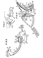
- Fig. 1 is a perspective view showing a device according to a first embodiment of the present invention, the device being used solely by female users for rinsing their private parts after defecation and/or urination;
- Fig. 2 is a central longitudinal section through the device shown in Fig. 1;
- Fig. 3 is a top plan view of Fig. 1;
- Fig. 4 is an exploded perspective view of Fig. 1;
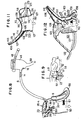
- Fig. 5 is a perspective view of a modified device used solely by male users and operating on the same principle as the embodiment of Fig. 1;
- Fig. 6 is a perspective view of a further modified device used solely by bedridden female users and operating on the same principle as the embodiment of Fig. 1;
- Fig. 7 is a view showing the operating state of the device shown in Fig. 6;
- Fig. 8 is a perspective view showing the device of Fig. 5 which is adapted to be used by bedridden male users;
- Fig. 9 is a view showing the operating state of the device shown in Fig. 8.
- Fig. 10 is a side elevation showing the device of Fig. 1 or Fig. 5 in conjunction with a reclining type bed.
- Fig. 11 is a side elevation, shown partially in section and showing a device for automatically rinsing private parts after defecation and/or urination of the female user according to a modified embodiment of the present invention;.
- Fig. 12 is a perspective view of a modified device adapted to be used by bedridden female users and operating under the same operating principle as the device of Fig. 11;
- Fig. 13 is a perspective view of another modified device adapted to be used by bedridden male users and operating under the same operating principle as the device of Fig. 11;
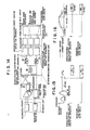
- Fig. 14 is a block diagram showing a sensor unit, a defecation/urination discriminating unit and a rinsing liquid discharging unit of the device shown in Fig. 1;
- Fig. 15 shows a timing chart showing the state of rinsing after defecation by the rinsing device shown in Fig. 1;
- Fig. 16 shows a timing chart showing the state of rinsing after urination by the rinsing device shown in Fig. 1;
- Fig. 17 shows a timing chart showing the state of rinsing after defecation and urination by the rinsing device shown in Fig. 1;
- Fig. 18A(i), 18B(ii) and 18C(iii) show the step of discarding cold water, the step of rinsing and the end of rinsing by the operation of the magnetic valve for urination of the device shown in Fig. 11, respectively, wherein Figs. 18A(a), 18B(b) and 18C(c) show the step of discarding cold water, the step of rinsing and the end of rinsing by the operation of the magnetic valve for defecation, respectively, of the device shown in Fig. 11;
- Fig. 19 shows a modification in which the piping for rinsing the anus and that for rinsing the urethra are branched at the water heater;
- Figs. 20A and 20B show further modified forms of Fig. 19;
- Fig. 21 is a block diagram showing the sensor unit, defecation/urination discriminating unit and the rinsing liquid discharging unit of the rinsing device of Fig. 11;
- Fig. 22 is a timing chart showing the state of rinsing after urination by the device shown in Fig. 11;
- Fig. 23 is a timing chart showing the state of rinsing after defecation by the device shown in Fig. 11; and
- Fig. 24 is a timing chart showing the state of rinsing after defecation and urination by the device shown in Fig. 11.
- The automatic rinsing device according to preferred embodiments of the present invention will be hereafter explained by referring to the accompanying drawings.
- Referring first to Figs. 1 to 4, the
main body 1 of the rinsing device has an upper opening water-tightly contacting with private parts including a defecation opening (anus) and a urination opening (urethra) of the user's body. It has fourupper attachment members 11 for engagement with fourbelts 3 acting as means for temporarily attaching the device to the user's body. Asafety cover 6 for inhibiting water leakage is mounted integrally to themain body 1 at a juncture 12 along with a lower base 7 and aspring 8 in such a manner that the upper opening of themain body 1 will overlie not only the anus which is the opening for defecation but also the urethra which is the opening for urination of the female user. Thecover 6 is comprised of abase joint section 5 and anelongated trough 6 extending from the joint section. Thespring 8 is adapted to press the waterleakage safety cover 6 into intimate fitting with the private portions of the user's body. A shock-absorbing bellows-like member 10 is provided at the upper portion of thecover 6 which is the portion to contact with the user's body, in such a manner that the bellows-like member 10 is contiguous to a water-proofingmember 9 provided on anupper frame 13 at the upper opening of themain body 1. The bellows-like member 10 is used as a packing to water-tightly seal the contacting portion with the user's body to prevent the rinsing liquid from leaking to outside of the rinsing device in cooperation with the water-proofingcushioning member 9. Inside thecover 6 is a reflux member ordeflector 15 adapted to guide the rinsing liquid from the rinse liquid nozzle towards the urethral opening for rinsing the private portion including the urethral opening to then return the used rinsing liquid towards the toilet bowl. To thisdeflector 15 is attached a temperature and/orhumidity sensor 16 to sense the urination. The output signals from the sensor are coupled to a defecation/urination discriminating unit which will be described. Aguide piping 14 is adapted to guide the rinsing water from the nozzle towards the urethral opening and secured to thereflux member 15 by welding or with an adhesive. - Below the
main body 1 is a discharge opening 50 communicating with atoilet bowl 17, Fig. 7, for discharging the used rinsing water with the waste material. The opening 50 is connected with the toilet bowl lying in the direction of an arrow mark in Fig. 2 either directly or via a connecting hose, not shown, preferably anelectric heater 27 for warming the private parts is provided on the perimeter of the opening 50, the temperature of which is controlled to a preset constant value by a thermostat, not shown. In addition to thesensor 16, apressure sensor 19 is also provided within themain body 1 of the rinsing device, the pressure sensor being disposed below the anus which is the opening for defecation, while also being vertically movable about afulcrum 18. The signal from thesensor 19 is supplied to a defecation/urination discriminating unit as later described. - Although the rinsing water may be supplied from the water main directly, the water supplied from the main may be stored in a
water tank 20 and then supplied to awater heater 21 where it is heated to a suitable temperature and transmitted as rinsing warm water through apiping 22. - Referring to Fig. 2, a
nozzle 24 is disposed in awater inlet port 23 and provided at predetermined distances with a plurality of iron segments 25-1, 25-2 and 25-3 operatively associated with timer-electro-magnets 26-1, 26-2, 26-3, 26-4 and 26-5. These electro-magnets are excited in dependence upon urination and/or defecation as sensed by the aforementioned sensors for shifting thenozzle 24 towards the opening for defecation and/or that for urination. Referring more specifically to Figs. 14 and 17, in case of urination, an output signal indicating the state of urination from changes in temperature or humidity rises sharply throughamplifier 28 of amalfunction safety unit 31. The amplified signal is compared in acomparator 29 with a voltage previously set on a potentiometer 30. When the output from thecomparator 29 exceeds a preset value, timer 47 is started to produce a signal to command the discharge of rinsing water to take place after lapse of a certain time, as in 90 seconds after the end of urination, as shown in Fig. 16. The numeral 32 denotes a variable resistor for calibrating the operating temperature of thetemperature sensor 16 of thesensor unit 33 as a function of seasonal changes in ambient atmospheric temperature. The signal from thecomparator 29 of theunit 31 is passed through ANDgate 35 and NAND acircuit 36 of a defecation/urination discriminating unit 34 in order to recognize urination. By the operation of a nozzle-shifting electro-magnet for urination- timer-magnetexciting circuit 45, a pair of electro-magnets 26-5 on both sides of themain body 1 are excited for shifting thenozzle 24 from its normal position facing to the electro-magnet 26-4 in the direction of theguide pipe 14 for holding the nozzle in this position for 20 seconds, see Figs. 2 and 16. The signal indicating urination at the defecation/urination discriminating unit 34 causes an electro-magnet, not shown, of thewater inlet port 23 to be opened with the aid of a urination timer-magnetic valve circuit 43 for emitting a rinsing liquid at 40 from the nozzle for 25 seconds in the direction of theguide pipe 14, Figs. 2 and 16. Thecircuit 45 is fitted with the timer in order that the nozzle will be transferred in the direction of theguide pipe 14 after lapse of 5 seconds since the opening of the electro-magnet 45 for emitting the warm rinsing liquid from the water heater to the private parts of the body, Fig. 16. In this manner, the water which will flow in cold state from the water heater to the nozzle port in winter is not discharged directly to the private portions of the user's body. - Then, as shown in Figs. 14 and 15, the signal that has sensed the state of urination at the
pressure sensor 19 of thesensor unit 33 ceases for 60 seconds in order to wait for complete cessation of defecation with the aid of thetimer 37 of themalfunction safety unit 31. The signal is then passed through ANDgate 35 andNAND b gate 44 of the unit 34 to recognize the defecation to then excite the electro-magnets 26-1, 26-2 and 26-3 with the aid of a nozzle-shifting electro-magnet-timer-magnetexciting circuit 46 for shifting thenozzle 24 in the direction of the anus which is the opening for defecation so that thenozzle 24 will remain in this position for about 60 seconds, see Fig. 2. The signal indicative of the state of defecation in the defecation/urination discriminating unit 34 causes the magnetic valve, not shown, of thewater inlet port 23 to be opened with the aid of a defecation timer-magnetic valve circuit 39 of a rinsingliquid discharging unit 38 for discharging the rinsing liquid at 40 for 65 seconds from the nozzle to the anus which is the opening of defecation. The nozzle-shifting electro-magnet for defecation-timer-magnet exciting circuit can be designed, as shown in Fig. 15, to shift the nozzle in 5 seconds after the opening of the magnetic valve to prevent the cold water from being discharged to the private portions. - Then, referring to Figs. 14 and 17, the signals indicative of both the defecation and urination at the
pressure sensor 19 and the temperature orhumidity sensor 16 of thesensor unit 33 are passed through themalfunction safety unit 31 to recognize both the defecation and urination at the ANDgate 35 of the discrimination unit 34. The resulting signal is transmitted via nozzle-shifting electro-magnet-timer-magnet exciting circuit 41 for sequentially exciting electro-magnets 26-5, 26-1, 26-2 and 26-3 with the aid of the timer in such a manner that, in 90 seconds after the urination signal has first reached a predetermined voltage value, the nozzle is directed towards the opening for urination and a rinsing liquid is discharged for 25 seconds for rinsing the opening for urination for 20 seconds, and that, in 60 seconds after the end of defecation, the nozzle is directed towards the anus and the magnetic valve, not shown, is opened by the defecation/urination timer-magnetic valve circuit 42 of the rinsingliquid discharging unit 38 to discharge the rinsing liquid for 65 seconds. It will be noted that the rinsing liquid is to be discharged for 5 seconds before nozzle shifting so as not to cause cold water to be discharged to the private portions of the user's body. - Fig. 5 shows the inventive automatic rinsing device adapted for male users. The device shown in Fig. 5 differs from the embodiment shown in Figs. 1 through 4 in that the
leakage safety cover 6 is a long tube in which a temperature orhumidity sensor 16 for sensing the urination and aguide pipe 14 are led closely to awashing pouch 48 into which the opening of male user's urethral opening is introduced and that afastener 49 including a hook, loop and a string for attachment to a penis is mounted to thewashing pouch 48. In other respects, the present embodiment is similar to the device for the female user described in connection with Figs. 1 through 4. - Fig. 6 shows an automatic rinsing device which is used by female users as the embodiment shown in Fig. 1. The present embodiment differs from the device shown in Fig. 1 in that it is adapted to be used by bedridden patients. The rinsing device of the present device has a
water inlet port 23 from the water supply system at the front lower side of themain body 1 and awater discharge port 50 communicating with toilet bowl 17 (Fig. 7) at the rear side of themain body 1. In addition, the timer-nozzle-shifting electro-magnets 26-1, 26-2, 26-3, 26-4 and 26-5 of the defecation/urination discriminating unit 34 and thenozzle 24 are provided to thewater inlet port 23. The nozzle-shifting electro-magnet for urination- - timer-magnet
exciting circuit 45 is operatively associated with the timer-nozzle-shifting electro-magnet for urination 26-4. Similarly, the nozzle-shifting electro-magnet for defecation-timer-magnetexciting circuit 46 is operatively associated with the timer-nozzle-shifting electro-magnet for defecation 26-5, and the nozzle-shifting electro-magnet for defecation/urination-timer-magnet exciting circuit 41 is operatively associated with the timer-nozzle-shifting electro-magnets for defecation/urination 26-4 and 26-5, with the timer-nozzle-shifting electro-magnets 26-1, 26-2 and 26-3 indicating the normal position for thenozzle 24. In Fig. 6, the numeral 56 denotes a water deflector below the user's buttock and the numeral 57 a spring adapted to fit the water-cushioningmember 9 with the buttock. Fig. 7 shows the state in which the present rinsing device is mounted in position to permit the user to urinate on aseat 52 of the toilet bowl mounted on the bed. In the drawing, the numeral 53 denotes a front side warm air discharge port from an air heater, not shown, and the numeral 54 a rear side warm air discharge port from anair heater 55 adapted for drying the private parts after rinsing. - Fig. 8 shows an automatic rinsing device for males similar to the embodiment shown in Fig. 5. The device of Fig. 8 differs from the device shown in Fig. 5 in that it is used by bedridden users. The device shown in Fig. 8 has a
water inlet port 23 from the water supply device at the front lower side of themain body 1 and awater discharge port 50 communicating with thetoilet bowl 17 at the rear side of themain body 1. The device shown in Fig. 8 also has anozzle 24, timer-nozzle-shifting electro-magnets 26-1, 26-2, 26-3, 26-4and 26-5, and adrain tube 58 in thepouch 48 for draining the used rinse water and urine into thetoilet bowl 17. The parts used in the device of Fig. 8 are configured similarly to the corresponding parts used in Fig. 6. Fig. 9 shows the state in which the device shown in Fig. 8 is mounted in position to permit the user to defecate on the seat of thetoilet bowl 17 mounted on the bed. - Fig. 10 shows the state in which the device shown in Fig. 1 or 5 is used in conjunction with a
reclining type bed 51 to permit the user to defecate with a part of the bed used as a backrest. In this figure, the numeral 61 designates a tank in which is stored the waste material delivered from thetoilet bowl 17 through a wastematerial drainage pipe 62 and a vacuum unit, not shown. The reclining can be achieved by extending or contracting a pair ofcylinders sensor 33 at the time of urination and/or defecation, Figs. 1 and 5. - The automatic rinsing device according to a modified embodiment of the present invention will be explained by referring to Figs. 11 through 13. The device shown in Fig. 11, corresponds to the device shown in Figs. 1 to 5. The device shown in Fig. 12 corresponds to the device shown in Fig. 6, while the device shown in Fig. 13 corresponds to the device shown in Fig. 8. The devices shown in Figs. 11, 12, and 13 are similar to the devices shown in Figs. 1-5, 6 and 8 of the first embodiment except that
stationary nozzles 124, 124' are used in place of themovable nozzle 24 provided with the iron segments 25-1,25-2 and 25-3 and the timer-electro-magnets 26-1, 26-2, 26-3, 26-4 and 26-5. For this reason, the parts shown in Figs. 11 through 13 and similar to those used in the above described first embodiment are denoted by the same numerals but added by 100 and the corresponding description is omitted. Similarly, when reference is made to Figs. 18 through 24 for explaining the second embodiment, the same or similar parts as those used in the first embodiment are denoted by the same reference numerals added by 100 and the corresponding description is not made for simplicity. - Referring now to Figs. 18 and 21, the signal from a
comparator 129 of amalfunction safety unit 131 is transmitted through an ANDgate 135 and a NAND agate 136 of the defecation/urination discriminating unit 134 to recognize only urination. By signals from theunit 134 indicating urination, the magnetic valves a and b for urination between the water supply device and the water supply port are opened with the aid of the urination timer-magnetic valve circuit 143 of the rinsingliquid discharging unit 138 to discharge rinsing liquid at 140 for 10 seconds from the nozzle towards theguide pipe 114. Referring more particularly to Figs. 18A(i), 18B(ii), 18C(iii) and 22, the 15-second timer of the magnetic valve a for urination is actuated to turn on the magnetic valve a for urination to discard the cold rinsing water from the water heater 121 (Fig. 19) to the valve into thetoilet bowl 17, see (i). The magnetic valve b for urination is turned on for 10 seconds by the 10-second timer of the magnetic valve b for urination for emitting the rinsing liquid to the private parts, see (ii), the valves a and b being then turned off, see (iii). In this manner, there may be avoided a situation in which the cold water between the valve and the water heater is emitted directly to the private parts during the aforementioned 5 seconds in winter. - In Figs. 11, 18A, B and C, the water passage between the water heater 121 and the valve is divided into a
defecation nozzle 124 and a urination nozzle 124' with the use of a bifurcated pipe. Alternatively, the piping for defecation and that for urination may be directly divided from the water heater 121. Fig. 20 shows a further embodiment in which a heat reserving device 125 such as a heater is provided in the water passage between the water heater 121 and the valve. In this case, the timer for the magnetic valve c for urination may be turned on for 10 seconds by the operation of the circuit 145 to turn on the magnetic valve c for urination, Fig. 20A, so that the warm water will be discharged at 140 to the private parts of the user's body. - The signal from the
pressure sensor 119 of thesensor unit 133 indicating defecation, Fig. 21, is transmitted to themalfunction safety circuit 137 of themalfunction safety unit 131 where the signal ceases for 60 seconds in order to wait for complete cessation of defecation. The output signal from theunit 131 is then transmitted through the ANDgate 135 andNAND b gate 144 of the defecation/urination discriminating unit 134 in order to ascertain excretion of faeces. On the other hand, the signal from theunit 134 indicating defecation causes the magnetic valves a and b between the water supply unit and thewater inlet port 123 to be opened with the aid of the defecation timer-magnetic valve circuit 139 of the rinseliquid discharging unit 138 to discharge the rinsing liquid at 140 for 60 seconds from the nozzle towards the anus which is the opening for defecation. Referring to Figs. 18A(a), 18B(b), 18C(c) and 23, it is also possible in this case to turn on the magnetic valve for defecation a only for discarding the cold rinsing liquid between the water heater 121 and the valve for 5 seconds into thetoilet bowl 17, Fig. 18A(a), the magnet valve for defecation b then being turned off for 60 seconds with the aid of the 60-second timer of the magnetic valve b to discharge the rinsing liquid to the private parts, Fig. 18B(b), the valves a and b then being turned off, Fig. 18C(c). In this manner, there is no risk of directly discharging cold water towards the private parts. When the heat reserving means 125 such as an electric heater is provided between the water heater 121 and the valve, as shown in Figs. 20(A) and 20(B), the magnetic valve c for defecation may be activated for 60 seconds by the operation of the defecation timer-magnetic valve circuit 139 to turn on the valve c, Fig. 20(B), to discharge warm water to the private parts at 140. - The signals from the
pressure sensor 119 and the temperature orhumidity sensor 116 of thesensor unit 133 indicating both defecation and urination, Fig. 24, are transmitted viamalfunction safety unit 131 to ascertain excretion of both faeces and urine by the ANDgate 135 of the discriminatingunit 134. The output signal from theunit 134 indicating both defecation and urination is transmitted to the defecation/urination timer-magnetic valve 142 of the rinseliquid discharging unit 138. The defecation/urination timer-magnetic valve circuit 142 operates as follows: The signal from the urination sensor causes the magnetic valves a and b for urination between the water supply device and thewater inlet port 123 to be turned on to permit the rinse liquid to be discharged for 10 seconds from the nozzle towards theguide pipe 114. The signal from thedefecation sensor 119 causes magnetic valves for defecation a and b to be turned on to permit the rinsing liquid to be discharged at 140 from the nozzle towards the anus for 60 seconds after lapse of 60 seconds since the end of defecation. It will be noted that the magnetic valve b for urination or defecation is turned on 5 seconds before the valve a to drain cold water into thetoilet bowl 17 instead of discharging it towards the private parts. Alternatively, when the heater or the likeheat reserving means 25 is provided as described hereinabove, the timer-magnetic valve circuit 142 may be so designed that the timer of each magnetic valve c for defecation or urination is started in 60 seconds after the end of defecation to turn on the magnetic valves for urination and defecation c, c connecting to thenozzle 124 for defecation and to the nozzle 124' for urination, so as to discharge warm water at 140 towards the private parts.
Claims (35)
Priority Applications (1)
| Application Number | Priority Date | Filing Date | Title |
|---|---|---|---|
| AT86105748T ATE47663T1 (en) | 1985-04-27 | 1986-04-25 | DEVICE FOR AUTOMATIC FLUSHING OF THE INTIMATE PARTS OF DISABLED PEOPLE AFTER DEFECTION AND/OR URINATING. |
Applications Claiming Priority (4)
| Application Number | Priority Date | Filing Date | Title |
|---|---|---|---|
| JP60091743A JPH0244224B2 (en) | 1985-04-27 | 1985-04-27 | HAIBENYOJIDOSENJOSOCHI |
| JP91743/85 | 1985-04-27 | ||
| JP60125138A JPS61284222A (en) | 1985-06-11 | 1985-06-11 | Automatic washing apparatus for evacuation |
| JP125138/85 | 1985-06-11 |
Publications (3)
| Publication Number | Publication Date |
|---|---|
| EP0200174A2 EP0200174A2 (en) | 1986-11-05 |
| EP0200174A3 EP0200174A3 (en) | 1987-12-02 |
| EP0200174B1 true EP0200174B1 (en) | 1989-11-02 |
Family
ID=26433187
Family Applications (1)
| Application Number | Title | Priority Date | Filing Date |
|---|---|---|---|
| EP86105748A Expired EP0200174B1 (en) | 1985-04-27 | 1986-04-25 | Device for automatic rinsing of private parts after defecation and/or urination of physically disabled persons |
Country Status (4)
| Country | Link |
|---|---|
| US (1) | US4791686A (en) |
| EP (1) | EP0200174B1 (en) |
| KR (1) | KR890002017B1 (en) |
| DE (1) | DE3666664D1 (en) |
Cited By (1)
| Publication number | Priority date | Publication date | Assignee | Title |
|---|---|---|---|---|
| DE102010053690A1 (en) * | 2010-12-08 | 2012-06-14 | EMOTEC Aktiengesellschaft Elektro-, Metall- und Oberflächentechnik | Apparatus for sanitary disposal of human excretion of bedridden person, has control device that controls actuator for safe inclination of the adapter to set inclination value based on detected inclination of adapter |
Families Citing this family (52)
| Publication number | Priority date | Publication date | Assignee | Title |
|---|---|---|---|---|
| JPH02126629U (en) * | 1989-03-28 | 1990-10-18 | ||
| EP0494488A1 (en) * | 1991-01-07 | 1992-07-15 | Kawasaki, Seiji | Excrement disposing system |
| KR960000389B1 (en) * | 1993-06-07 | 1996-01-06 | 이성규 | Portable toilet |
| US5842237A (en) * | 1996-02-15 | 1998-12-01 | Lotecon, Llc | Convertible bed/chair with waste disposal |
| JP3097029B2 (en) * | 1996-10-09 | 2000-10-10 | 多摩重起建設株式会社 | Nursing bed with flush toilet |
| ES2136543B1 (en) * | 1997-05-08 | 2000-07-01 | Roman Lopez Francisco | PORTABLE ANATOMIC SANITARY DEVICE AND URINE DEVICE. |
| JPH1147180A (en) * | 1997-07-29 | 1999-02-23 | Niles Parts Co Ltd | Excrement disposal device |
| EP0956848B1 (en) * | 1998-05-12 | 2006-03-08 | Teruo Kitamura | Device for washing crotch region of patient |
| JP3077085B1 (en) * | 1999-02-16 | 2000-08-14 | ナイルス部品株式会社 | Excrement disposal device |
| JP2001112802A (en) * | 1999-10-18 | 2001-04-24 | Niles Parts Co Ltd | Excretion treatment apparatus |
| DE19956722A1 (en) * | 1999-11-25 | 2001-06-13 | Helmut Utz | Toilet facilities, especially for bedridden people |
| ATE310483T1 (en) * | 2000-08-17 | 2005-12-15 | Hanmedics Co Ltd 6 Fl Graduate | URINE COLLECTION DEVICE WITH WASHING DEVICE |
| JP3388734B1 (en) * | 2001-11-22 | 2003-03-24 | 株式会社ビルメン鹿児島 | Nursing toilet system |
| US6641567B1 (en) * | 2002-01-24 | 2003-11-04 | Maryjane Williams | Incontinence diaper and receptacle apparatus |
| US20050070860A1 (en) * | 2003-09-30 | 2005-03-31 | Teruo Kitamura | Device for disposing excrements |
| WO2005041829A1 (en) * | 2003-10-31 | 2005-05-12 | Toshiharu Honda | Excrement treating apparatus |
| AU2006233435A1 (en) * | 2005-04-11 | 2006-10-19 | Zhenhua Liu | Human waste automatic processor |
| US20060247604A1 (en) * | 2005-04-29 | 2006-11-02 | Bruno Roy R | Lavage chair and method of use |
| KR20070107532A (en) * | 2006-05-03 | 2007-11-07 | 주식회사 노비타 | Auto washing device of biedet and control method thereof |
| KR100735833B1 (en) * | 2006-06-26 | 2007-07-06 | 주식회사 엘쓰리 | A flush simple urinal |
| FR2905593B1 (en) * | 2006-09-13 | 2009-08-21 | Univ Paris Curie | UNDERWEAR FOR INCONTINENT PERSON AND TREATMENT DEVICE ASSOCIATED WITH UNDERWEAR |
| JP4567757B2 (en) * | 2008-02-05 | 2010-10-20 | 稔 中村 | Automatic urine processing equipment |
| ITMI20081705A1 (en) * | 2008-09-26 | 2010-03-27 | Serenum Srl | SELF-CLEANING ELECTROMEDICAL MACHINE FOR WASH AND ANTI-GENITAL ANTI-DRYING OF PEOPLE WHO ARE PATIENTS AND FOR THE FOLLOWING ELIMINATION OF FECES AND URINE PRODUCED BY THE SAME PEOPLE NON-SELF-SUFFICIENT PATIENTS |
| KR100942204B1 (en) * | 2009-08-11 | 2010-02-11 | 주식회사 큐라코 | Automatic excrement treating apparatus adjustable nozzle height |
| CN101933857B (en) * | 2010-08-25 | 2012-01-04 | 杭州亿脑智能科技有限公司 | Intelligent nursing machine |
| CN102296686A (en) * | 2011-06-21 | 2011-12-28 | 东莞市新福乐医疗器械有限公司 | Method for automatically treating defecation |
| CN103306345B (en) * | 2012-03-06 | 2016-03-30 | 陈润 | The manual instrument for defecation of toilet |
| US11806266B2 (en) | 2014-03-19 | 2023-11-07 | Purewick Corporation | Apparatus and methods for receiving discharged urine |
| US11376152B2 (en) | 2014-03-19 | 2022-07-05 | Purewick Corporation | Apparatus and methods for receiving discharged urine |
| US10952889B2 (en) | 2016-06-02 | 2021-03-23 | Purewick Corporation | Using wicking material to collect liquid for transport |
| US11090183B2 (en) | 2014-11-25 | 2021-08-17 | Purewick Corporation | Container for collecting liquid for transport |
| CN104173157B (en) * | 2014-09-09 | 2017-04-26 | 柳丰萍 | Urine and excrement collection device and hospital bed |
| US10358807B2 (en) * | 2014-11-25 | 2019-07-23 | Shandong Crrc Huateng Environment Co., Ltd. | Suction seat for intelligent nursing toilet bowl |
| CN106999332B (en) * | 2014-12-01 | 2020-08-25 | 酷洁有限公司 | Excrement treatment device comprising male module having body-facing opening |
| WO2016125926A1 (en) * | 2015-02-03 | 2016-08-11 | 이훈상 | Excreta disposal apparatus comprising gender-specific module |
| USD928946S1 (en) | 2016-06-02 | 2021-08-24 | Purewick Corporation | Urine receiving apparatus |
| US10973678B2 (en) | 2016-07-27 | 2021-04-13 | Purewick Corporation | Apparatus and methods for receiving discharged urine |
| CN106726087A (en) * | 2017-01-14 | 2017-05-31 | 苏州欧圣电气工业有限公司 | A kind of Wearable cleaning device work head |
| TR201721930A2 (en) * | 2017-12-26 | 2019-07-22 | Aslan Ali Pirli | Functional panty waste removal unit |
| CN112367948A (en) | 2018-05-01 | 2021-02-12 | 普利维克公司 | Fluid collection devices, related systems, and related methods |
| BR112020022139A2 (en) | 2018-05-01 | 2021-01-26 | Purewick Corporation | fluid collection devices, systems and methods |
| CA3098680A1 (en) | 2018-05-01 | 2019-11-07 | Purewick Corporation | Fluid collection garments |
| CN109044673B (en) * | 2018-08-26 | 2021-03-16 | 张惠丽 | Detection mechanism capable of automatically shifting, wiping and drying after detection to recover detection function |
| US10689836B1 (en) | 2018-12-31 | 2020-06-23 | Kelley Simon | Handheld personal perineal cleansing system and methods |
| US11708688B2 (en) | 2018-12-31 | 2023-07-25 | Kelley Simon | Personal perineal cleansing system and methods |
| US11234562B1 (en) | 2018-12-31 | 2022-02-01 | Kelley Simon | Handheld personal perineal cleansing system and methods |
| USD929578S1 (en) | 2019-06-06 | 2021-08-31 | Purewick Corporation | Urine collection assembly |
| USD967409S1 (en) | 2020-07-15 | 2022-10-18 | Purewick Corporation | Urine collection apparatus cover |
| US11801186B2 (en) | 2020-09-10 | 2023-10-31 | Purewick Corporation | Urine storage container handle and lid accessories |
| WO2022159392A1 (en) | 2021-01-19 | 2022-07-28 | Purewick Corporation | Variable fit fluid collection devices, systems, and methods |
| WO2022182385A1 (en) | 2021-02-26 | 2022-09-01 | Purewick Corporation | Fluid collection devices having a sump between a tube opening and a barrier, and related systems and methods |
| US11938054B2 (en) | 2021-03-10 | 2024-03-26 | Purewick Corporation | Bodily waste and fluid collection with sacral pad |
Family Cites Families (14)
| Publication number | Priority date | Publication date | Assignee | Title |
|---|---|---|---|---|
| DE1016904B (en) * | 1953-10-10 | 1957-10-03 | Elektro Therapie M B H Ges | Chair-like intestinal bath facility |
| US3626941A (en) * | 1968-08-06 | 1971-12-14 | Donald D Webb | Excretory prosthesis |
| US3757355A (en) * | 1971-09-09 | 1973-09-11 | R Allen | Portable body waste collecting system |
| DE2200033A1 (en) * | 1972-01-03 | 1973-07-19 | Herbert Arnds | PLUG BASIN |
| DE2325260A1 (en) * | 1972-05-26 | 1973-12-13 | Huyot | SANITARY-HYGIENIC DEVICE |
| JPS5330273B2 (en) * | 1973-05-07 | 1978-08-25 | ||
| GB1563343A (en) * | 1975-11-10 | 1980-03-26 | Combi Co | Urinating receiver |
| US4137579A (en) * | 1977-12-20 | 1979-02-06 | Soler Peter S | Urine drain |
| US4237560A (en) * | 1978-12-28 | 1980-12-09 | Rusco Industries, Inc. | Bidet system and water tank therein |
| JPS5750009Y2 (en) * | 1979-03-12 | 1982-11-02 | ||
| DE3381050D1 (en) * | 1982-11-09 | 1990-02-08 | Matsushita Electric Ind Co Ltd | SANITARY WASHING DEVICE. |
| JPS59155252A (en) * | 1983-02-25 | 1984-09-04 | 本多 「まさ」夫 | Automatic excretion treating device |
| US4610675A (en) * | 1983-09-06 | 1986-09-09 | David Triunfol | Device for collecting fluid discharged from female organs |
| US4631061A (en) * | 1984-06-19 | 1986-12-23 | Martin Frank D | Automatic urine detecting, collecting and storing device |
-
1986
- 1986-04-22 US US06/855,170 patent/US4791686A/en not_active Expired - Fee Related
- 1986-04-25 DE DE8686105748T patent/DE3666664D1/en not_active Expired
- 1986-04-25 EP EP86105748A patent/EP0200174B1/en not_active Expired
- 1986-04-26 KR KR1019860003226A patent/KR890002017B1/en not_active IP Right Cessation
Cited By (1)
| Publication number | Priority date | Publication date | Assignee | Title |
|---|---|---|---|---|
| DE102010053690A1 (en) * | 2010-12-08 | 2012-06-14 | EMOTEC Aktiengesellschaft Elektro-, Metall- und Oberflächentechnik | Apparatus for sanitary disposal of human excretion of bedridden person, has control device that controls actuator for safe inclination of the adapter to set inclination value based on detected inclination of adapter |
Also Published As
| Publication number | Publication date |
|---|---|
| EP0200174A2 (en) | 1986-11-05 |
| KR890002017B1 (en) | 1989-06-08 |
| KR860007923A (en) | 1986-11-10 |
| EP0200174A3 (en) | 1987-12-02 |
| US4791686A (en) | 1988-12-20 |
| DE3666664D1 (en) | 1989-12-07 |
Similar Documents
| Publication | Publication Date | Title |
|---|---|---|
| EP0200174B1 (en) | Device for automatic rinsing of private parts after defecation and/or urination of physically disabled persons | |
| JP4065002B2 (en) | Automatic defecation processing device | |
| US8196230B2 (en) | Automatic treating device for urination and defecation | |
| KR101015717B1 (en) | Automatic processing apparatus for human body's excrement | |
| JP4119462B2 (en) | Automatic defecation processing device | |
| US8407838B2 (en) | Automatic fecal and urinary treatment device | |
| JP4643523B2 (en) | Automatic defecation processing device | |
| JP2009183423A (en) | Detection system for toilet unit for use in supine position | |
| KR100905529B1 (en) | Automatic excretion cleaner and the method | |
| JP2009142384A (en) | Excrement disposal device | |
| JP2008011999A (en) | Automatic excrement treatment apparatus | |
| JP2006055513A (en) | Excrement disposal device | |
| KR100829524B1 (en) | Automatic Excretion Cleaner | |
| EP2399561A1 (en) | Automatic fecal and urinary treatment device | |
| KR100905530B1 (en) | Automatic excretion cleaner | |
| JP4663747B2 (en) | Excrement disposal device | |
| JPH0244224B2 (en) | HAIBENYOJIDOSENJOSOCHI | |
| JP4476052B2 (en) | Excrement disposal system and diaper | |
| JPS61284222A (en) | Automatic washing apparatus for evacuation | |
| JP4167278B2 (en) | Automatic defecation processing device | |
| KR20190092186A (en) | Automatic Feces Collector | |
| JPH07241308A (en) | Sanitary device for care | |
| JP4699959B2 (en) | Automatic defecation processing device | |
| JP2008029759A (en) | Automatic defecation disposal device | |
| JP3001721U (en) | Nursing hygiene equipment |
Legal Events
| Date | Code | Title | Description |
|---|---|---|---|
| PUAI | Public reference made under article 153(3) epc to a published international application that has entered the european phase |
Free format text: ORIGINAL CODE: 0009012 |
|
| AK | Designated contracting states |
Kind code of ref document: A2 Designated state(s): AT BE CH DE FR GB IT LI NL SE |
|
| PUAL | Search report despatched |
Free format text: ORIGINAL CODE: 0009013 |
|
| AK | Designated contracting states |
Kind code of ref document: A3 Designated state(s): AT BE CH DE FR GB IT LI NL SE |
|
| 17P | Request for examination filed |
Effective date: 19871229 |
|
| 17Q | First examination report despatched |
Effective date: 19880510 |
|
| ITF | It: translation for a ep patent filed |
Owner name: STUDIO INGG. FISCHETTI & WEBER |
|
| GRAA | (expected) grant |
Free format text: ORIGINAL CODE: 0009210 |
|
| AK | Designated contracting states |
Kind code of ref document: B1 Designated state(s): AT BE CH DE FR GB IT LI NL SE |
|
| PG25 | Lapsed in a contracting state [announced via postgrant information from national office to epo] |
Ref country code: BE Effective date: 19891102 Ref country code: AT Effective date: 19891102 |
|
| REF | Corresponds to: |
Ref document number: 47663 Country of ref document: AT Date of ref document: 19891115 Kind code of ref document: T |
|
| ET | Fr: translation filed | ||
| REF | Corresponds to: |
Ref document number: 3666664 Country of ref document: DE Date of ref document: 19891207 |
|
| PLBE | No opposition filed within time limit |
Free format text: ORIGINAL CODE: 0009261 |
|
| STAA | Information on the status of an ep patent application or granted ep patent |
Free format text: STATUS: NO OPPOSITION FILED WITHIN TIME LIMIT |
|
| 26N | No opposition filed | ||
| ITTA | It: last paid annual fee | ||
| PGFP | Annual fee paid to national office [announced via postgrant information from national office to epo] |
Ref country code: CH Payment date: 19940427 Year of fee payment: 9 |
|
| PGFP | Annual fee paid to national office [announced via postgrant information from national office to epo] |
Ref country code: NL Payment date: 19940430 Year of fee payment: 9 |
|
| EAL | Se: european patent in force in sweden |
Ref document number: 86105748.7 |
|
| PGFP | Annual fee paid to national office [announced via postgrant information from national office to epo] |
Ref country code: SE Payment date: 19950418 Year of fee payment: 10 Ref country code: GB Payment date: 19950418 Year of fee payment: 10 |
|
| PGFP | Annual fee paid to national office [announced via postgrant information from national office to epo] |
Ref country code: FR Payment date: 19950426 Year of fee payment: 10 |
|
| PG25 | Lapsed in a contracting state [announced via postgrant information from national office to epo] |
Ref country code: LI Effective date: 19950430 Ref country code: CH Effective date: 19950430 |
|
| PG25 | Lapsed in a contracting state [announced via postgrant information from national office to epo] |
Ref country code: NL Effective date: 19951101 |
|
| REG | Reference to a national code |
Ref country code: CH Ref legal event code: PL |
|
| NLV4 | Nl: lapsed or anulled due to non-payment of the annual fee |
Effective date: 19951101 |
|
| PG25 | Lapsed in a contracting state [announced via postgrant information from national office to epo] |
Ref country code: GB Effective date: 19960425 |
|
| PG25 | Lapsed in a contracting state [announced via postgrant information from national office to epo] |
Ref country code: SE Effective date: 19960426 |
|
| PGFP | Annual fee paid to national office [announced via postgrant information from national office to epo] |
Ref country code: DE Payment date: 19960620 Year of fee payment: 11 |
|
| GBPC | Gb: european patent ceased through non-payment of renewal fee |
Effective date: 19960425 |
|
| PG25 | Lapsed in a contracting state [announced via postgrant information from national office to epo] |
Ref country code: FR Effective date: 19961227 |
|
| EUG | Se: european patent has lapsed |
Ref document number: 86105748.7 |
|
| REG | Reference to a national code |
Ref country code: FR Ref legal event code: ST |
|
| PG25 | Lapsed in a contracting state [announced via postgrant information from national office to epo] |
Ref country code: DE Free format text: LAPSE BECAUSE OF NON-PAYMENT OF DUE FEES Effective date: 19980101 |
|
| PG25 | Lapsed in a contracting state [announced via postgrant information from national office to epo] |
Ref country code: IT Free format text: LAPSE BECAUSE OF NON-PAYMENT OF DUE FEES;WARNING: LAPSES OF ITALIAN PATENTS WITH EFFECTIVE DATE BEFORE 2007 MAY HAVE OCCURRED AT ANY TIME BEFORE 2007. THE CORRECT EFFECTIVE DATE MAY BE DIFFERENT FROM THE ONE RECORDED. Effective date: 20050425 |