EP0201154A1 - Fixing device - Google Patents
Fixing device Download PDFInfo
- Publication number
- EP0201154A1 EP0201154A1 EP86300801A EP86300801A EP0201154A1 EP 0201154 A1 EP0201154 A1 EP 0201154A1 EP 86300801 A EP86300801 A EP 86300801A EP 86300801 A EP86300801 A EP 86300801A EP 0201154 A1 EP0201154 A1 EP 0201154A1
- Authority
- EP
- European Patent Office
- Prior art keywords
- sleeve
- nut
- fixing device
- bolt
- screw
- Prior art date
- Legal status (The legal status is an assumption and is not a legal conclusion. Google has not performed a legal analysis and makes no representation as to the accuracy of the status listed.)
- Granted
Links
- 238000004873 anchoring Methods 0.000 claims abstract description 6
- 238000000605 extraction Methods 0.000 claims abstract description 3
- 230000002093 peripheral effect Effects 0.000 claims abstract description 3
- 239000000203 mixture Substances 0.000 claims description 5
- 239000013536 elastomeric material Substances 0.000 claims description 3
- 229920003052 natural elastomer Polymers 0.000 claims description 3
- 229920001194 natural rubber Polymers 0.000 claims description 3
- 229920003051 synthetic elastomer Polymers 0.000 claims description 3
- 239000005061 synthetic rubber Substances 0.000 claims description 3
- 244000043261 Hevea brasiliensis Species 0.000 claims description 2
- 229920001971 elastomer Polymers 0.000 description 4
- 239000005060 rubber Substances 0.000 description 4
- 241001622623 Coeliadinae Species 0.000 description 3
- 239000000463 material Substances 0.000 description 3
- 238000000465 moulding Methods 0.000 description 3
- 239000007787 solid Substances 0.000 description 3
- 229910001369 Brass Inorganic materials 0.000 description 2
- 229910000831 Steel Inorganic materials 0.000 description 2
- 239000010951 brass Substances 0.000 description 2
- 230000000694 effects Effects 0.000 description 2
- 238000003780 insertion Methods 0.000 description 2
- 230000037431 insertion Effects 0.000 description 2
- 239000010959 steel Substances 0.000 description 2
- 239000000654 additive Substances 0.000 description 1
- 230000032683 aging Effects 0.000 description 1
- 239000003963 antioxidant agent Substances 0.000 description 1
- 239000007767 bonding agent Substances 0.000 description 1
- 238000013329 compounding Methods 0.000 description 1
- 239000000945 filler Substances 0.000 description 1
- 238000009472 formulation Methods 0.000 description 1
- 239000011796 hollow space material Substances 0.000 description 1
- 239000004615 ingredient Substances 0.000 description 1
- 230000003993 interaction Effects 0.000 description 1
- 238000004519 manufacturing process Methods 0.000 description 1
- 239000002184 metal Substances 0.000 description 1
- 238000000034 method Methods 0.000 description 1
- 238000012986 modification Methods 0.000 description 1
- 230000004048 modification Effects 0.000 description 1
- 239000000049 pigment Substances 0.000 description 1
- 230000000717 retained effect Effects 0.000 description 1
- 239000003381 stabilizer Substances 0.000 description 1
- 229910001220 stainless steel Inorganic materials 0.000 description 1
- 239000010935 stainless steel Substances 0.000 description 1
- 230000003313 weakening effect Effects 0.000 description 1
Images
Classifications
-
- F—MECHANICAL ENGINEERING; LIGHTING; HEATING; WEAPONS; BLASTING
- F16—ENGINEERING ELEMENTS AND UNITS; GENERAL MEASURES FOR PRODUCING AND MAINTAINING EFFECTIVE FUNCTIONING OF MACHINES OR INSTALLATIONS; THERMAL INSULATION IN GENERAL
- F16B—DEVICES FOR FASTENING OR SECURING CONSTRUCTIONAL ELEMENTS OR MACHINE PARTS TOGETHER, e.g. NAILS, BOLTS, CIRCLIPS, CLAMPS, CLIPS OR WEDGES; JOINTS OR JOINTING
- F16B37/00—Nuts or like thread-engaging members
- F16B37/12—Nuts or like thread-engaging members with thread-engaging surfaces formed by inserted coil-springs, discs, or the like; Independent pieces of wound wire used as nuts; Threaded inserts for holes
- F16B37/122—Threaded inserts, e.g. "rampa bolts"
-
- F—MECHANICAL ENGINEERING; LIGHTING; HEATING; WEAPONS; BLASTING
- F16—ENGINEERING ELEMENTS AND UNITS; GENERAL MEASURES FOR PRODUCING AND MAINTAINING EFFECTIVE FUNCTIONING OF MACHINES OR INSTALLATIONS; THERMAL INSULATION IN GENERAL
- F16B—DEVICES FOR FASTENING OR SECURING CONSTRUCTIONAL ELEMENTS OR MACHINE PARTS TOGETHER, e.g. NAILS, BOLTS, CIRCLIPS, CLAMPS, CLIPS OR WEDGES; JOINTS OR JOINTING
- F16B13/00—Dowels or other devices fastened in walls or the like by inserting them in holes made therein for that purpose
- F16B13/04—Dowels or other devices fastened in walls or the like by inserting them in holes made therein for that purpose with parts gripping in the hole or behind the reverse side of the wall after inserting from the front
- F16B13/06—Dowels or other devices fastened in walls or the like by inserting them in holes made therein for that purpose with parts gripping in the hole or behind the reverse side of the wall after inserting from the front combined with expanding sleeve
- F16B13/061—Dowels or other devices fastened in walls or the like by inserting them in holes made therein for that purpose with parts gripping in the hole or behind the reverse side of the wall after inserting from the front combined with expanding sleeve of the buckling type
-
- F—MECHANICAL ENGINEERING; LIGHTING; HEATING; WEAPONS; BLASTING
- F16—ENGINEERING ELEMENTS AND UNITS; GENERAL MEASURES FOR PRODUCING AND MAINTAINING EFFECTIVE FUNCTIONING OF MACHINES OR INSTALLATIONS; THERMAL INSULATION IN GENERAL
- F16B—DEVICES FOR FASTENING OR SECURING CONSTRUCTIONAL ELEMENTS OR MACHINE PARTS TOGETHER, e.g. NAILS, BOLTS, CIRCLIPS, CLAMPS, CLIPS OR WEDGES; JOINTS OR JOINTING
- F16B29/00—Screwed connection with deformation of nut or auxiliary member while fastening
Definitions
- the present invention relates to a fixing device, comprising a flexible sleeve having at one end a nut for receiving a screw or bolt, for anchoring the screw or bolt in a hole in a structure.
- a device of this type which has been known for at least thirty years comprises a rubber flexible sleeve having a brass or brass-plated hexagonal nut embedded therein at one of its ends.
- the sleeve has an integrally moulded annular flange at its other end.
- the nut is hexagonal in order to anchor it securely in the sleeve.
- the use of a hexagonal nut led to difficulties in the production of the device.
- the sleeve is passed through a hole in, for instance, a sheet metal panel until the flange abuts the panel.
- a bolt is then passed into the sleeve and is screwed into the nut.
- the sleeve is compressed axially and is therefore forced to expand radially.
- the radial expansion of the sleeve produces a protuberance abutting the panel which prevents the device from being withdrawn from the hole.
- a fixing device for anchoring a screw or bolt in a hole in a structure, comprising a flexible sleeve having a nut, for receiving the screw or bolt, fixedly disposed in the sleeve near one end thereof, the peripheral surface of the nut being enclosed by the sleeve, wherein the outer surface of the sleeve is provided with: annular ribs for hindering extraction of the radially expanded sleeve from the hole; and at least one axial rib protruding marginally beyond the cylindrical outer surface of the sleeve for hindering rotation of the sleeve during screwing of the screw or bolt into or out of the nut.
- axial ribs there are two axial ribs disposed diametrically opposite one another.
- any number of axial ribs can alternatively be used so long as their presence does not interfere with the operation of the annular ribs.
- the amount the axial rib(s) protrude(s) will depend on the size of the hole into which the sleeve is to be placed. The amount should not be so great as to prevent the annular ribs, once the sleeve has been radially expanded, from contacting firmly the sides of the hole. The amount of protuberance can be readily determined by trial and error experimentation by the skilled person. As a general guide it is preferable that the radius to the outside of an axial rib should not be more than 110% of the radius of the sleeve.
- the annular ribs are asyimetric about a olane oerpendicular to the axis of the sleeve, are verticulart is aiventagecus if the side of each rib remcte from the nut is parallel to that plane and the other side of each rib is angled inwardly, conveniently at an angle of about 45°,towards the nut. This facilitates insertion of the sleeve into the hole but makes it much more difficult to extract the radially expanded sleeve from the hole.
- the annular and axial ribbing on the sleeve is preferably located in a single central area of the sleeve.
- the ribbing may extend the whole length of the sleeve or may be formed in a number of separate areas of the sleeve.
- the ribbing is preferably formed by moulding the sleeve in the appropriate shape. Alternatively the ribs could be cut out of the sleeve or adhered thereto.
- the sleeve may be made from any flexible material, but is preferably made from an elastomeric material such as natural rubber, synthetic rubber or blends thereof.
- the elastomeric material may contain pigments, fillers, antioxidants, stabilisers or any of the other additives known in the art.
- Particularly suitable elastomeric materials are rubber compositions used to produce vehicle tyres.
- the nut may be fixed in the sleeve by any of the methods known in the art.
- the sleeve may be moulded around a nut blank which is subsequently tapped to provide an internal thread.
- the nut may be adhesively secured or bonded in a recess in a pre-formed sleeve.
- a combination of moulding and'bonding may be used.
- the nut may be of any desired shape, but is preferably circular, and may be made from any suitable material such as steel, stainless steel, brass or brass-plated steel.
- annular flange may be fcrres on the end of ⁇ he sleeve remcte from the nut. This will be necessary if it is intended to insert the sleeve into a hollow space behind a panel. However, it will not be necessary if the hole is formed as a well in a solid structure such as a road or factory floor.
- the fixing device of the present invention will be of use in any of the applications for which the prior art fixing devices have been used.
- the fixing device of the present invention will be of particular use in fixing bolts or screws in solid structures such as roads or factory floors.
- a hole is formed in the surface and a fixing device according to the invention of appropriate dimensions is placed in the hole.
- the device will be of such dimensions that the axial ribs engage the wall of the hole.
- the bolt is then inserted into the sleeve and screwed into the nut.
- any tendency for the sleeve to turn in the hole is removed by the interaction of the axial ribs and the wall of the hole.
- the sleeve As the bolt is screwed into the nut, the sleeve is compressed axially and is therefore expanded radially. This brings the annular ribs into tight abutment with the wall of the hole. The annular ribs will be able to physically interlock with rough areas on the wall so that the sleeve is retained in the hole by more than just friction between the wall and the sleeve.
- the fixing device of the present invention overcomes the disadvantages of known fixing devices cf the same type.
- the fixing device 1 comprises a cylindrical sleeve 3 made from a high quality rubber, comprising a blend of natural and synthetic rubber together with the appropriate ingredients to give excellent ageing and low set characteristics.
- a high quality rubber comprising a blend of natural and synthetic rubber together with the appropriate ingredients to give excellent ageing and low set characteristics.
- Such rubbers and their formulation and compounding are well known in the art.
- the sleeve 3 defines a through bore 4 for receiving therein a bolt (not shown).
- the device 1 further comprises a circular nut 5 fixed into one end of the sleeve 3.
- the nut 5 was provided with a pretapped thread and the sleeve was moulded around the blank.
- the nut 5 was further fixed in the sleeve 3 by application of a bonding agent to the exterior unthreaded area of the nut before the moulding of the sleeve 3.
- the sleeve 3 has formed on the outside of a central section thereof two diametrically opposed axial ribs 9 and a plurality of annular ribs 11.
- the axial ribs 9 protrude marginally beyond the outer surface of the sleeve 3, but the edges of the annular ribs 11 are in the same plane as the outer surface of the sleeve 3.
- the annular ribs 11 each comprise a surface 11a remote from the nut 5 which is perpendicular to the axis of the sleeve 3 and a surface 11t adjacent the nut 5 which is angled inwardly towards the nut 5.
- the fixing device 1 is placed into, for instance, a blind well in a road surface with its nut 5 adjacent the blind end of the well and its other end adjacent the road surface.
- the diameter of the well should be the same as or marginally smaller than the diameter of the sleeve including the axial ribs 9. Due tc their shape, the annular ribs 11 do not significantly interfere with insertion of the sleeve 3 into the well.
- a "sleeping policemen" is then fixed to the road surface by passing a bolt through a suitable hole in the sleeping policeman and into the sleeve 3. The bolt is then screwed into the nut 5. Since the axial ribs 9 abut tightly the wall of the well, there is little or no tendency for the sleeve 3 to rotate in the well, thus facilitating screwing up of the bolt.
- the sleeve 3 As the bolt is screwed into the nut 5, the sleeve 3 is compressed axially between the nut 5 and the bottom of the sleeping policeman. This causes the sleeve 3 to expand radially, thus bringing the annular ribs 11 into tight abutment with the wall of the well. This of itself will make it difficult to remove the sleeve 3 from the well. However, this effect is enhanced by the shape of the annular ribs 11, the surfaces lla of which will physically interlock with the wall of the well.
- the fixing device of the present invention has been used to anchor a machine tool to a factory floor. This has proved to be a very effective way of anchoring the machine tool, and there has been no sign of any weakening of the anchorage.
Abstract
Description
- The present invention relates to a fixing device, comprising a flexible sleeve having at one end a nut for receiving a screw or bolt, for anchoring the screw or bolt in a hole in a structure.
- A device of this type which has been known for at least thirty years comprises a rubber flexible sleeve having a brass or brass-plated hexagonal nut embedded therein at one of its ends. The sleeve has an integrally moulded annular flange at its other end. The nut is hexagonal in order to anchor it securely in the sleeve. However, the use of a hexagonal nut led to difficulties in the production of the device.
- A proposal for overcoming these difficulties is described in GB-A-1,392,095. In the device described in this patent specification, the hexagonal nut is replaced by a cylindrical nut which preferably has in its outer surface a circumferential groove for keying the nut into the sleeve.
- In use of these devices, the sleeve is passed through a hole in, for instance, a sheet metal panel until the flange abuts the panel. A bolt is then passed into the sleeve and is screwed into the nut. As the bolt screws into the nut, the sleeve is compressed axially and is therefore forced to expand radially. The radial expansion of the sleeve produces a protuberance abutting the panel which prevents the device from being withdrawn from the hole.
- It has recently been proposed to use a fixing device of this type to anchor articles such as "sleeping policemen" or machinery to solid surfaces, such as roads or factory floors. However, it has been found that in cases where considerable force is exerted on the fixing device, for instance by traffic passing at ordinary speeds over a sleeping policeman, it is not possible properly to anchor the device on the surface. Moreover, it has proved difficult fully to insert the bolt in the nut since the whole device tends to rotate during the screwing of the bolt into the nut.
- It is an aim of the present invention to prcvide- an improved fixing device of the type described above.
- According to the present invention, there is provided a fixing device, for anchoring a screw or bolt in a hole in a structure, comprising a flexible sleeve having a nut, for receiving the screw or bolt, fixedly disposed in the sleeve near one end thereof, the peripheral surface of the nut being enclosed by the sleeve, wherein the outer surface of the sleeve is provided with: annular ribs for hindering extraction of the radially expanded sleeve from the hole; and at least one axial rib protruding marginally beyond the cylindrical outer surface of the sleeve for hindering rotation of the sleeve during screwing of the screw or bolt into or out of the nut.
- Preferably, there are two axial ribs disposed diametrically opposite one another. However, any number of axial ribs can alternatively be used so long as their presence does not interfere with the operation of the annular ribs.
- The amount the axial rib(s) protrude(s) will depend on the size of the hole into which the sleeve is to be placed. The amount should not be so great as to prevent the annular ribs, once the sleeve has been radially expanded, from contacting firmly the sides of the hole. The amount of protuberance can be readily determined by trial and error experimentation by the skilled person. As a general guide it is preferable that the radius to the outside of an axial rib should not be more than 110% of the radius of the sleeve.
- Preferably, the annular ribs are asyimetric about a olane oerpendicular to the axis of the sleeve, are verticulart is aiventagecus if the side of each rib remcte from the nut is parallel to that plane and the other side of each rib is angled inwardly, conveniently at an angle of about 45°,towards the nut. This facilitates insertion of the sleeve into the hole but makes it much more difficult to extract the radially expanded sleeve from the hole.
- The annular and axial ribbing on the sleeve is preferably located in a single central area of the sleeve. Alternatively, the ribbing may extend the whole length of the sleeve or may be formed in a number of separate areas of the sleeve.
- The ribbing is preferably formed by moulding the sleeve in the appropriate shape. Alternatively the ribs could be cut out of the sleeve or adhered thereto.
- The sleeve may be made from any flexible material, but is preferably made from an elastomeric material such as natural rubber, synthetic rubber or blends thereof. The elastomeric material may contain pigments, fillers, antioxidants, stabilisers or any of the other additives known in the art. Particularly suitable elastomeric materials are rubber compositions used to produce vehicle tyres.
- The nut may be fixed in the sleeve by any of the methods known in the art. For instance the sleeve may be moulded around a nut blank which is subsequently tapped to provide an internal thread. Alternatively, the nut may be adhesively secured or bonded in a recess in a pre-formed sleeve. In a further alternative a combination of moulding and'bonding may be used.
- The nut may be of any desired shape, but is preferably circular, and may be made from any suitable material such as steel, stainless steel, brass or brass-plated steel.
- If desired an integral annular flange may be fcrres on the end of τhe sleeve remcte from the nut. This will be necessary if it is intended to insert the sleeve into a hollow space behind a panel. However, it will not be necessary if the hole is formed as a well in a solid structure such as a road or factory floor.
- It is envisaged that the fixing device of the present invention will be of use in any of the applications for which the prior art fixing devices have been used. However, the fixing device of the present invention will be of particular use in fixing bolts or screws in solid structures such as roads or factory floors.
- In use in such an application, a hole is formed in the surface and a fixing device according to the invention of appropriate dimensions is placed in the hole. The device will be of such dimensions that the axial ribs engage the wall of the hole.
- The bolt is then inserted into the sleeve and screwed into the nut. As the bolt is screwed into the nut, any tendency for the sleeve to turn in the hole is removed by the interaction of the axial ribs and the wall of the hole.
- As the bolt is screwed into the nut, the sleeve is compressed axially and is therefore expanded radially. This brings the annular ribs into tight abutment with the wall of the hole. The annular ribs will be able to physically interlock with rough areas on the wall so that the sleeve is retained in the hole by more than just friction between the wall and the sleeve.
- It can thus be seen that the fixing device of the present invention overcomes the disadvantages of known fixing devices cf the same type.
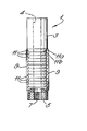
- One embodiment of a fixing device according to the invention is described below, by way of example only. with reference to the accompanying drawing which is a front view, partly in section, of the fixing device.
- Referring now to the drawing, the fixing device 1 comprises a cylindrical sleeve 3 made from a high quality rubber, comprising a blend of natural and synthetic rubber together with the appropriate ingredients to give excellent ageing and low set characteristics. Such rubbers and their formulation and compounding are well known in the art.
- The sleeve 3 defines a through
bore 4 for receiving therein a bolt (not shown). - The device 1 further comprises a circular nut 5 fixed into one end of the sleeve 3. The nut 5 was provided with a pretapped thread and the sleeve was moulded around the blank. The nut 5 was further fixed in the sleeve 3 by application of a bonding agent to the exterior unthreaded area of the nut before the moulding of the sleeve 3.
- The sleeve 3 has formed on the outside of a central section thereof two diametrically opposed
axial ribs 9 and a plurality ofannular ribs 11. - The
axial ribs 9 protrude marginally beyond the outer surface of the sleeve 3, but the edges of theannular ribs 11 are in the same plane as the outer surface of the sleeve 3. Theannular ribs 11 each comprise asurface 11a remote from the nut 5 which is perpendicular to the axis of the sleeve 3 and a surface 11t adjacent the nut 5 which is angled inwardly towards the nut 5. - In use, the fixing device 1 is placed into, for instance, a blind well in a road surface with its nut 5 adjacent the blind end of the well and its other end adjacent the road surface. The diameter of the well should be the same as or marginally smaller than the diameter of the sleeve including the
axial ribs 9. Due tc their shape, theannular ribs 11 do not significantly interfere with insertion of the sleeve 3 into the well. - A "sleeping policemen" is then fixed to the road surface by passing a bolt through a suitable hole in the sleeping policeman and into the sleeve 3. The bolt is then screwed into the nut 5. Since the
axial ribs 9 abut tightly the wall of the well, there is little or no tendency for the sleeve 3 to rotate in the well, thus facilitating screwing up of the bolt. - As the bolt is screwed into the nut 5, the sleeve 3 is compressed axially between the nut 5 and the bottom of the sleeping policeman. This causes the sleeve 3 to expand radially, thus bringing the
annular ribs 11 into tight abutment with the wall of the well. This of itself will make it difficult to remove the sleeve 3 from the well. However, this effect is enhanced by the shape of theannular ribs 11, the surfaces lla of which will physically interlock with the wall of the well. - It has been found that, if a fixing device of the present invention is used, it is extremely difficult for traffic moving at ordinary, or even excessive, speeds to remove sleeping policemen from a road surface. Using the fixing devices of the prior art, it was possible for traffic to overcome the anchoring effect of the device.
- Moreover, the fixing device of the present invention has been used to anchor a machine tool to a factory floor. This has proved to be a very effective way of anchoring the machine tool, and there has been no sign of any weakening of the anchorage.
- It is nonetheless easy to remove the anchored article merely by unscrewing the bolt. This will be facilitated by the presence of the
axial ribs 9 which will prevent the sleeve 3 from rotating while the bolt is being unscrewed. - It will be appreciated that the fixing device of the present invention has been described above by way of example only and that modifications and variations of detail may be made, as will be apparent to the man skilled in the art, without departing from the spirit and scope of the invention.
Claims (10)
Priority Applications (1)
| Application Number | Priority Date | Filing Date | Title |
|---|---|---|---|
| AT86300801T ATE43158T1 (en) | 1985-05-10 | 1986-02-06 | FIXING DEVICE. |
Applications Claiming Priority (2)
| Application Number | Priority Date | Filing Date | Title |
|---|---|---|---|
| GB858511843A GB8511843D0 (en) | 1985-05-10 | 1985-05-10 | Fixing device |
| GB8511843 | 1985-05-10 |
Publications (2)
| Publication Number | Publication Date |
|---|---|
| EP0201154A1 true EP0201154A1 (en) | 1986-11-12 |
| EP0201154B1 EP0201154B1 (en) | 1989-05-17 |
Family
ID=10578921
Family Applications (1)
| Application Number | Title | Priority Date | Filing Date |
|---|---|---|---|
| EP86300801A Expired EP0201154B1 (en) | 1985-05-10 | 1986-02-06 | Fixing device |
Country Status (5)
| Country | Link |
|---|---|
| EP (1) | EP0201154B1 (en) |
| AT (1) | ATE43158T1 (en) |
| BR (1) | BR8602085A (en) |
| DE (1) | DE3663385D1 (en) |
| GB (1) | GB8511843D0 (en) |
Cited By (2)
| Publication number | Priority date | Publication date | Assignee | Title |
|---|---|---|---|---|
| US6533930B1 (en) | 1998-07-31 | 2003-03-18 | Access Business Group International Llc | Point-of-use water treatment system |
| WO2021123746A1 (en) * | 2019-12-16 | 2021-06-24 | Three Smith Group Limited | Anchor assembly |
Citations (3)
| Publication number | Priority date | Publication date | Assignee | Title |
|---|---|---|---|---|
| GB1392095A (en) * | 1972-07-26 | 1975-04-23 | Rawlplug Co Ltd | Fixing device |
| CH577639A5 (en) * | 1973-09-07 | 1976-07-15 | Hilti Befestigungstechnik Ag | |
| WO1982004106A1 (en) * | 1981-05-18 | 1982-11-25 | Mortensen Louis Aackersberg | A tubular screw anchoring member |
-
1985
- 1985-05-10 GB GB858511843A patent/GB8511843D0/en active Pending
-
1986
- 1986-02-06 EP EP86300801A patent/EP0201154B1/en not_active Expired
- 1986-02-06 DE DE8686300801T patent/DE3663385D1/en not_active Expired
- 1986-02-06 AT AT86300801T patent/ATE43158T1/en not_active IP Right Cessation
- 1986-05-09 BR BR8602085A patent/BR8602085A/en unknown
Patent Citations (3)
| Publication number | Priority date | Publication date | Assignee | Title |
|---|---|---|---|---|
| GB1392095A (en) * | 1972-07-26 | 1975-04-23 | Rawlplug Co Ltd | Fixing device |
| CH577639A5 (en) * | 1973-09-07 | 1976-07-15 | Hilti Befestigungstechnik Ag | |
| WO1982004106A1 (en) * | 1981-05-18 | 1982-11-25 | Mortensen Louis Aackersberg | A tubular screw anchoring member |
Cited By (9)
| Publication number | Priority date | Publication date | Assignee | Title |
|---|---|---|---|---|
| US6533930B1 (en) | 1998-07-31 | 2003-03-18 | Access Business Group International Llc | Point-of-use water treatment system |
| US6716343B2 (en) | 1998-07-31 | 2004-04-06 | Access Business Group International Llc | Point-of-use water treatment system |
| US6716345B2 (en) | 1998-07-31 | 2004-04-06 | Access Business Group International Llc | Point-of-use water treatment system |
| US6726839B2 (en) | 1998-07-31 | 2004-04-27 | Access Business Group International Llc | Point-of-use water treatment system |
| US6773587B2 (en) | 1998-07-31 | 2004-08-10 | Access Business Group International Llc | Point-of-use water treatment system |
| US6811691B2 (en) | 1998-07-31 | 2004-11-02 | Access Business Group International Llc | Point-of-use water treatment system |
| US6949185B2 (en) | 1998-07-31 | 2005-09-27 | Alticor Inc. | Point-of-use water treatment system |
| US7166216B2 (en) | 1998-07-31 | 2007-01-23 | Access Business Group International, Llc | Point-of-use water treatment system |
| WO2021123746A1 (en) * | 2019-12-16 | 2021-06-24 | Three Smith Group Limited | Anchor assembly |
Also Published As
| Publication number | Publication date |
|---|---|
| DE3663385D1 (en) | 1989-06-22 |
| ATE43158T1 (en) | 1989-06-15 |
| GB8511843D0 (en) | 1985-06-19 |
| BR8602085A (en) | 1987-01-06 |
| EP0201154B1 (en) | 1989-05-17 |
Similar Documents
| Publication | Publication Date | Title |
|---|---|---|
| US5131795A (en) | Screw threaded insert | |
| AU2004214536B2 (en) | Threaded screw fastener characterized by high pull-out resistance, reduced intstallation torque, and unique head structure and drive socket implement or tool therefor | |
| US4861206A (en) | Straddling plug | |
| US4601625A (en) | Self drilling threaded insert for drywall | |
| US4789284A (en) | Self-cutting expansion anchor | |
| US8360701B2 (en) | Threaded fastener | |
| US4887951A (en) | Dual composite headed self-threading screw | |
| US5425407A (en) | Screw plug for tire punctures | |
| AU588634B2 (en) | Expander device | |
| JPH0424570B2 (en) | ||
| US3345899A (en) | Synthetic resin fasteners | |
| US10344789B2 (en) | Self-drilling drywall anchor and a method of securing an anchor in a drywall | |
| IE49136B1 (en) | Expanding fixing plug | |
| AU2004201507B2 (en) | Screw anchor | |
| US20030007846A1 (en) | Fastening means | |
| CA2084565C (en) | Sleeve for increasing retention value of a screw | |
| EP0201154B1 (en) | Fixing device | |
| WO1999047821A1 (en) | New system for holding and tightening screws | |
| KR20030011849A (en) | Self-tapping bush-shaped screwed insert | |
| US4708550A (en) | Resistance between nut and bolt | |
| KR950033136A (en) | Insert Nuts and Fasteners | |
| GB2226835A (en) | Mining tool | |
| EP0134231B2 (en) | Fixing element for knocking into a drilled hole | |
| CA2002847A1 (en) | Panel anchor | |
| EP0437932B1 (en) | Inserts |
Legal Events
| Date | Code | Title | Description |
|---|---|---|---|
| PUAI | Public reference made under article 153(3) epc to a published international application that has entered the european phase |
Free format text: ORIGINAL CODE: 0009012 |
|
| AK | Designated contracting states |
Kind code of ref document: A1 Designated state(s): AT BE CH DE FR GB IT LI LU NL SE |
|
| RAP1 | Party data changed (applicant data changed or rights of an application transferred) |
Owner name: ROCOL LIMITED |
|
| 17P | Request for examination filed |
Effective date: 19870507 |
|
| 17Q | First examination report despatched |
Effective date: 19880322 |
|
| GRAA | (expected) grant |
Free format text: ORIGINAL CODE: 0009210 |
|
| AK | Designated contracting states |
Kind code of ref document: B1 Designated state(s): AT BE CH DE FR GB IT LI LU NL SE |
|
| PG25 | Lapsed in a contracting state [announced via postgrant information from national office to epo] |
Ref country code: IT Free format text: LAPSE BECAUSE OF FAILURE TO SUBMIT A TRANSLATION OF THE DESCRIPTION OR TO PAY THE FEE WITHIN THE PRESCRIBED TIME-LIMIT;WARNING: LAPSES OF ITALIAN PATENTS WITH EFFECTIVE DATE BEFORE 2007 MAY HAVE OCCURRED AT ANY TIME BEFORE 2007. THE CORRECT EFFECTIVE DATE MAY BE DIFFERENT FROM THE ONE RECORDED. Effective date: 19890517 Ref country code: CH Effective date: 19890517 Ref country code: SE Effective date: 19890517 Ref country code: LI Effective date: 19890517 Ref country code: NL Effective date: 19890517 Ref country code: BE Effective date: 19890517 Ref country code: AT Effective date: 19890517 |
|
| REF | Corresponds to: |
Ref document number: 43158 Country of ref document: AT Date of ref document: 19890615 Kind code of ref document: T |
|
| RAP4 | Party data changed (patent owner data changed or rights of a patent transferred) |
Owner name: ROCOL LIMITED |
|
| REF | Corresponds to: |
Ref document number: 3663385 Country of ref document: DE Date of ref document: 19890622 |
|
| ET | Fr: translation filed | ||
| REG | Reference to a national code |
Ref country code: CH Ref legal event code: PL |
|
| NLV1 | Nl: lapsed or annulled due to failure to fulfill the requirements of art. 29p and 29m of the patents act | ||
| PG25 | Lapsed in a contracting state [announced via postgrant information from national office to epo] |
Ref country code: LU Free format text: LAPSE BECAUSE OF NON-PAYMENT OF DUE FEES Effective date: 19900228 |
|
| PLBE | No opposition filed within time limit |
Free format text: ORIGINAL CODE: 0009261 |
|
| STAA | Information on the status of an ep patent application or granted ep patent |
Free format text: STATUS: NO OPPOSITION FILED WITHIN TIME LIMIT |
|
| 26N | No opposition filed | ||
| REG | Reference to a national code |
Ref country code: GB Ref legal event code: 732E |
|
| REG | Reference to a national code |
Ref country code: FR Ref legal event code: TP |
|
| REG | Reference to a national code |
Ref country code: GB Ref legal event code: IF02 |
|
| PGFP | Annual fee paid to national office [announced via postgrant information from national office to epo] |
Ref country code: FR Payment date: 20030117 Year of fee payment: 18 |
|
| PGFP | Annual fee paid to national office [announced via postgrant information from national office to epo] |
Ref country code: GB Payment date: 20030129 Year of fee payment: 18 |
|
| PGFP | Annual fee paid to national office [announced via postgrant information from national office to epo] |
Ref country code: DE Payment date: 20030228 Year of fee payment: 18 |
|
| PG25 | Lapsed in a contracting state [announced via postgrant information from national office to epo] |
Ref country code: GB Free format text: LAPSE BECAUSE OF NON-PAYMENT OF DUE FEES Effective date: 20040206 |
|
| PG25 | Lapsed in a contracting state [announced via postgrant information from national office to epo] |
Ref country code: DE Free format text: LAPSE BECAUSE OF NON-PAYMENT OF DUE FEES Effective date: 20040901 |
|
| GBPC | Gb: european patent ceased through non-payment of renewal fee |
Effective date: 20040206 |
|
| PG25 | Lapsed in a contracting state [announced via postgrant information from national office to epo] |
Ref country code: FR Free format text: LAPSE BECAUSE OF NON-PAYMENT OF DUE FEES Effective date: 20041029 |
|
| REG | Reference to a national code |
Ref country code: FR Ref legal event code: ST |