EP0201701B1 - Manual spray distributor - Google Patents
Manual spray distributor Download PDFInfo
- Publication number
- EP0201701B1 EP0201701B1 EP86104326A EP86104326A EP0201701B1 EP 0201701 B1 EP0201701 B1 EP 0201701B1 EP 86104326 A EP86104326 A EP 86104326A EP 86104326 A EP86104326 A EP 86104326A EP 0201701 B1 EP0201701 B1 EP 0201701B1
- Authority
- EP
- European Patent Office
- Prior art keywords
- valve
- piston
- pump
- valve body
- discharge
- Prior art date
- Legal status (The legal status is an assumption and is not a legal conclusion. Google has not performed a legal analysis and makes no representation as to the accuracy of the status listed.)
- Expired - Lifetime
Links
Images


Classifications
-
- B—PERFORMING OPERATIONS; TRANSPORTING
- B05—SPRAYING OR ATOMISING IN GENERAL; APPLYING FLUENT MATERIALS TO SURFACES, IN GENERAL
- B05B—SPRAYING APPARATUS; ATOMISING APPARATUS; NOZZLES
- B05B11/00—Single-unit hand-held apparatus in which flow of contents is produced by the muscular force of the operator at the moment of use
- B05B11/0005—Components or details
- B05B11/0059—Components or details allowing operation in any orientation, e.g. for discharge in inverted position
-
- B—PERFORMING OPERATIONS; TRANSPORTING
- B05—SPRAYING OR ATOMISING IN GENERAL; APPLYING FLUENT MATERIALS TO SURFACES, IN GENERAL
- B05B—SPRAYING APPARATUS; ATOMISING APPARATUS; NOZZLES
- B05B11/00—Single-unit hand-held apparatus in which flow of contents is produced by the muscular force of the operator at the moment of use
- B05B11/01—Single-unit hand-held apparatus in which flow of contents is produced by the muscular force of the operator at the moment of use characterised by the means producing the flow
- B05B11/10—Pump arrangements for transferring the contents from the container to a pump chamber by a sucking effect and forcing the contents out through the dispensing nozzle
- B05B11/1001—Piston pumps
- B05B11/1023—Piston pumps having an outlet valve opened by deformation or displacement of the piston relative to its actuating stem
- B05B11/1026—Piston pumps having an outlet valve opened by deformation or displacement of the piston relative to its actuating stem the piston being deformable and its deformation allowing opening of the outlet
-
- B—PERFORMING OPERATIONS; TRANSPORTING
- B05—SPRAYING OR ATOMISING IN GENERAL; APPLYING FLUENT MATERIALS TO SURFACES, IN GENERAL
- B05B—SPRAYING APPARATUS; ATOMISING APPARATUS; NOZZLES
- B05B11/00—Single-unit hand-held apparatus in which flow of contents is produced by the muscular force of the operator at the moment of use
- B05B11/01—Single-unit hand-held apparatus in which flow of contents is produced by the muscular force of the operator at the moment of use characterised by the means producing the flow
- B05B11/10—Pump arrangements for transferring the contents from the container to a pump chamber by a sucking effect and forcing the contents out through the dispensing nozzle
- B05B11/1042—Components or details
- B05B11/1066—Pump inlet valves
- B05B11/1067—Pump inlet valves actuated by pressure
Definitions
- the invention relates to an output device with a thrust piston pump for discharging media, in particular liquids, from a storage vessel or the like.
- the pump In the top position and, conversely, in the upside-down position, the pump of which comprises a cylinder and, to delimit a pump chamber, a piston unit which can be moved by hand in this and an outlet channel and suction channels for the top and the top position, of which the suction channel for the top position is provided with a valve arrangement in the manner of a check valve that closes when there is overpressure in the pump chamber and in the top position when there is underpressure in the pump chamber, the two oppositely arranged valve seats each for the installation of one movable valve body, for example a ball.
- An atomizer has become known (DE-PS 28 18 560), in which two separate suction valves with separate valve bodies are provided axially one behind the other in the suction channel.
- one of the suction valves is used both in the top position and in the top position to close the suction channel during the pumping stroke, i.e. in the event of overpressure in the pump chamber, and the other suction valve is provided only in the head position under the weight force acting on the associated valve body during the return -. stroke of the pump piston to close this suction channel, so that a negative pressure builds up in the pump chamber and is drawn in towards the end of the return stroke only via a separate suction channel medium provided exclusively for the head position.
- the valve body of the first-mentioned suction valve In order to ensure that the medium is only discharged through the outlet channel and not back into the storage vessel during the subsequent pumping stroke, the valve body of the first-mentioned suction valve must be brought into the closed position against the weight of the medium by the flow of a portion of the medium displaced from the pump chamber .
- the second exhaust valve interferes with this process due to the flow resistances emanating from it, as a result of which the valve body of the first exhaust valve is prevented from being moved quickly or immediately into the closed position, which leads to deviations with regard to the amount of medium discharged during each pump stroke, that is, leads to metering inaccuracies.
- the arrangement of two separate valve bodies is also complex and takes up additional space.
- the invention has for its object to provide an output device of the type mentioned, in particular a double-acting valve arrangement in the manner described, which ensures a faster response in the respective operating position, in particular in the head position with a simplified design.
- valve seats are arranged at the two ends of a valve chamber receiving the valve body, which preferably has continuously constant internal cross sections between the two valve seats, so that the valve body, for example with an approximately axially aligned arrangement of the Valve seats can be kept practically on a straight trajectory.
- valve seat which is farther from the pump piston is formed by an insert body, in particular in the center axis of the pump piston, which is inserted into the end of an intake port of a cylinder housing forming the cylinder.
- This insert body can be mounted essentially one-sided as an insert body to be mc from the pump chamber and is suitable for additionally serving as a plug-in member for receiving an intake hose or the like to be attached in the manner of a riser pipe.
- valve seat closer to the pump piston i.e. the valve seat directly connected to the pump chamber, in such a way that it delimits a valve opening which, in the manner of a baffle jet nozzle, preferably narrowed in the direction of the valve body, in the direction is directed to the opposite valve seat against the valve body.
- the space between the impact jet nozzle and the valve body assigned to the opposite valve seat, which is formed by the same valve body which is also assigned to the valve seat delimiting the impact jet nozzle is thus completely free for the flow coming from the pump chamber during the pumping stroke, so that this flow immediately occurs act the valve body and can transfer this against its weight into the higher, associated closed position.
- a particularly advantageous embodiment in particular an output device of the type described, consists in that a mechanically opened in the outlet channel towards the end of the pump stroke netes outlet valve is arranged, the outlet valve body movable between the closed and the open position with an actuating head of the pump relative to the valve seat in the open position, this outlet valve serves to open the outlet channel only when a relatively high pressure has built up in the pump chamber is, so that the medium is suddenly discharged, which is particularly advantageous when the medium is to be atomized during discharge;
- the opening time of the exhaust valve can be controlled much more precisely if it is not controlled hydraulically via an intermediate piston influenced by the pressure in the pump chamber, but if it is mechanically controlled directly in relation to the pump stroke.
- valve seat of the outlet valve is formed by a sleeve-shaped piston sleeve forming the pump piston and penetrated by the outlet channel
- the outlet valve body can be displaced in a simple manner with a valve stem, for example, it can be slidably mounted on the inner circumferential surface of the piston sleeve, expedient to achieve favorable spatial conditions for the valve stem is on the outlet side of the closing surface of the valve body.
- the pump piston is stop-limited at the end of the pump stroke, in particular by an inner shoulder located at the end of the piston runway.
- the actuating head including the exhaust valve body is to be kept in this piston end position in relation to the pump piston in the valve opening position of the exhaust valve.
- the safe and immediate closing of the exhaust valve at the beginning or before the return stroke of the pump piston can be achieved in a very simple manner by arranging a return spring for the piston unit as a closing spring for the exhaust valve and preferably on the piston unit exclusively via the exhaust valve. Valve body is supported.
- the actuating head is mounted directly on the piston unit, in particular on a piston neck forming the outer end of the piston sleeve and slidably receiving the valve stem of the exhaust valve, so that the piston neck is thus slidably guided both on the inner circumference and on the outer circumference relative to the actuating head is and can therefore be made very thin-walled without the risk of compression.
- the actuating head receives the piston neck in a sliding sleeve, the actuating head, for example by means of an annular collar engaging in an annular groove, expediently between two end positions both in the direction of the pump stroke and in the direction of the return stroke, which are approximately the closed position and the open position of the Exhaust valves correspond to the valve seat of the exhaust valve or against the piston neck is limited.
- the actuating head for driving the outlet valve body has an inner stamp which preferably abuts the outer end face of the valve stem and delimits a section of the outlet channel lying in the center in the actuating head. This also ensures very simple assembly. However, it is also conceivable to design the actuating head in one piece with the outlet valve body, for example in such a way that the inner punch mentioned merges in one piece into the valve stem.
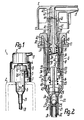
- an output device 1 which is to be attached to the neck 3 of a storage vessel 2 or the like, has a pump 4 designed as a thrust piston pump, which protrudes in or through the neck 3 with a fastening cap 5 is that the storage vessel 2 is tightly closed.
- a pump 4 designed as a thrust piston pump, which protrudes in or through the neck 3 with a fastening cap 5 is that the storage vessel 2 is tightly closed.
- the actuating head 7 projects partially into a cover cap 9 which receives the fastening cap 5 and the end of the pump housing 6 protruding therefrom, in which the actuating head 7 including the piston unit can be guided against rotation.
- the parts described lie in the central axis 10 of the thrust piston pump.
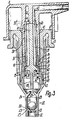
- the pump housing 6 is formed by a tubular cylinder housing 11 graduated in diameter and a sleeve-shaped cylinder cover 12 which is attached to the outer, further end of the cylinder housing 11 and has an annular collar 13 adjacent to its inner end face for sealing contact with the neck 3 of the vessel.
- the cylinder housing 11 forms a pump cylinder 14, the inner surface of which is provided as a piston raceway 15 for a pump piston 17 arranged at the inner end of the piston unit 16.
- the pump piston 17 has a sleeve-shaped piston lip 19 which is widened in the shape of a truncated cone in the direction of arrow 18 of the pump stroke, with its annular end edge, which at the same time forms the inner end of the piston unit 16 or the pump piston 17, it is guided in a sealed manner on the piston raceway 15.
- the pump piston 17 delimits a pump chamber 20 with the cylinder 14.
- the inner end of the cylinder housing 11 merges via a frustoconically tapered section into a reduced-diameter intake port 21, in which an intake valve arrangement 22 is provided which, in terms of action, comprises two intake valves 23, 24.
- the suction valves 23, 24 have separate, oppositely arranged valve seats 25, 26, but a single, common valve body 27, which in the exemplary embodiment shown is a ball that can move freely between the two valve seats 25, 26 in a valve chamber 28, but also by a valve body of a different spatial shape can be formed, which is then expediently guided between its functional positions in a predetermined position.
- valve seat 25 is the same, namely expanded in the shape of a truncated cone in the opposite or opposite direction, the valve chamber 28 being continuously cylindrical between the valve seats.
- the valve seat 26, which is closer to the pump chamber 20 and which is formed by a truncated cone jacket which projects freely in the direction of the pump chamber 20 and is formed in one piece with the cylinder housing 11 and lies in the region of the associated end of the intake port 21, limits the pump chamber 20 practically into the pump chamber 20 and the valve opening 29 lying in the central axis 10, which in the manner of an impact jet nozzle narrows conically in the shape of a truncated cone to the inside of the valve chamber 28 and is directed symmetrically against the valve body 27 such that a medium jet coming from it immediately throws the valve body 27 against the valve seat 25 .
- the other valve seat 25, whose valve opening is larger than the valve opening. 29 may be formed by a sleeve-shaped insert body 30, which is inserted into the inlet connector 21 from the end thereof and the outside diameter of which is substantially equal to the inside diameter of the valve chamber 28.
- the insert body 30 serves at the same time to fasten an intake hose 31 by insertion, this intake hose 31 extending directly in the vicinity of the bottom of the storage vessel 20 and limiting the intake duct of the pump 4 for the top position shown in FIGS. 1 to 3.
- the suction duct 33 for the head position turned around is formed by at least one, in particular a plurality of openings in the jacket of the cylinder 14 which are evenly distributed over the circumference and which penetrate the piston raceway 15 in a region which is directly adjacent to the contact edge of the piston lip 19 when the pump piston 17 is in the initial position lies.
- the suction channel 33 or the associated openings penetrate the outer circumference of the cylinder 14 in a region which, when the dispensing device 1 is mounted, is located directly adjacent to the neck 3 in the storage vessel 2, i.e. when the head is in the then approximately deepest area of the interior of the storage vessel intended for receiving the medium 2 lies, so that the storage vessel 2 can be emptied essentially completely with the pump 4 even in the top position.
- the piston unit 16 has a piston sleeve 34, which is formed in one piece with the sleeve-shaped hollow pump piston 17 and adjoins its rear end, which is also closed sleeve-shaped and extends outward beyond the outside of the pump housing 6 or the cylinder cover 12 into the outer part of the actuating head 7 enough.
- the piston sleeve 34 delimits an outlet channel 35 lying in it, which connects the pump chamber 20 through the pump piston 17 with the interposition of a mechanically opening outlet valve 36 with the outlet opening 8.
- the annular valve seat 37 of the outlet valve 36 lying approximately in the middle of the length of the piston sleeve 34 or in the region of the inner end of the cylinder cover 12 is formed by an annular bead 38 of the piston sleeve 34 protruding radially inwards.
- the valve body 39 of the outlet valve 36 lies completely inside the piston sleeve 34 essentially on the side of the valve seat 37 facing the pump chamber 20, its valve-conical surface 40 tapering outward in the shape of a truncated cone being formed by the end face of the collar-shaped valve body 39 facing away from the pump chamber 20.
- the valve body 39 is formed in one piece with a valve stem 41 which is slotted in the longitudinal direction or axially on the circumference in order to release the outlet channel 45 such that it is cross-shaped, for example, in cross-section and over its length has going cylindrical peripheral surfaces.
- the valve stem 41 is slidably guided in the outer piston neck 56 of the piston sleeve 34, which engages in the actuating head 7, parallel to the central axis 10, this cylindrical sliding surface of the piston sleeve 34 in the direction of the valve seat 27 becoming a frustoconically widened inner surface, so that the Execute valve stem 41 at least in the open position of the outlet valve 36 within narrow limits and allow the valve body 39 to align precisely with the valve seat 37.
- a return spring in the form of, for example, a helical compression spring located within the cylinder housing 11 is provided, which penetrates the pump piston 17 and, up to the valve body 39, the piston sleeve 34 and on the end face of the valve body 39 which is remote from the closing surface 40 and is perpendicular to the central axis 10 is supported.
- the valve body 39 On this end face, the valve body 39 has a protruding projection for centered engagement in the return spring 42.
- the other end of the return spring 42 lying in the pump chamber 20 is supported on an axially secured intermediate body 43 inserted directly adjacent to the valve opening 29 in the cylinder housing 11, which also engages with a centering projection in the return spring 42, this centering projection in every position of the pump piston 17 in. This protrudes.
- valve stem 41 extends to the outer end of the piston neck 56 such that the end face 44 of the valve stem 41 lies in the plane of the outer end face of the piston sleeve 34.
- the piston neck 56 of the piston sleeve 34 with a slight sliding fit is surrounded by a sliding sleeve 45 of the actuating head 7, this sliding sleeve 45 protruding into the pump housing 6 at every position of the piston unit 16 and opposite the actuating part designed to grip over the cylinder cover 12 in a cap-like manner of the actuating head 7 has a significantly smaller outer diameter.
- the piston sleeve 34 and the sliding sleeve 45 can engage in one another via an annular collar and an annular groove in such a way that they can be moved against one another in a limited manner between two axial end positions;
- the annular collar 46 engaging in an inner groove of the sliding sleeve 45 is provided on the outer circumference of the piston neck 56 near the outer end of the piston sleeve 34.
- the actuating head 7 rests with the free end of an inner punch 47 provided in the central axis 10, which lies in an annular section 48 of the outlet channel 35, from which the channel section leading to the outlet opening 8, for example perpendicular to the central axis 10, extends.
- the intermediate body 43 forms an annular inner shoulder 49 opposite the pump piston 19, which forms the end of the piston raceway 15 and directly adjoins it.
- the pump piston 17 runs with its front end face against this inner shoulder 49, the intermediate body 43 engaging with an annular shoulder projecting over the inner shoulder 49 into the piston lip 19 of the pump piston 17 in such a way that it bears against the inner surface of the piston lip 19 and this supports against deformation.
- the pump described works according to the following method: If the actuating head 7 is pressed down manually against the force of the return spring 42, the piston lip 19 passes over the openings in the piston raceway 15 of the suction channel 33 at the beginning of this movement, so that it is closed in the manner of a slide control ; in addition, the valve assembly 22 is already closed at the beginning of this movement in that the valve body 27 lies tightly against the valve seat 25. During the further movement, a pressure builds up in the pump chamber 20 until the pump piston 17 has reached the inner shoulder 49 and the pump piston 17 is thereby fixed against further movements in the direction of the pump stroke 18.
- the actuating head 7 is moved further in relation to the piston unit 16 or the valve seat 37 by the valve opening stroke 50 in the direction of arrow 18 of the pump stroke, such that the valve body 39 according to FIG. 3 against the force of the return spring 42 transferred to its open position and the outlet valve 36 was opened.
- the medium under pressure in the pump chamber 20 can thereby be discharged via the outlet valve 36 and through the outlet opening 8 of the actuating head 7.
- the manual return of the actuating head 7 initiates the return stroke, in which the valve body 39 is first moved into the closed position by the return spring 42, taking the actuating head 7 with it, after which the rest of the piston unit 16, i.e.
- valve closing surface 40 is seated on the valve seat 37
- Pump piston 17 is taken and transferred to the starting position.
- the valve body 27 of the valve assembly 22 lifts off the valve seat 25, the flow conditions being provided in such a way that the valve body 27 cannot get into its second closed position, namely into the closed position adjacent to the valve seat 26, so that 32 medium into the through the suction channel Pump chamber 20 is sucked.
- the next pump stroke can then be carried out in the manner described.
- valve body 27 falls under the weight force acting on it into the valve seat 26 and the medium located in the storage vessel 2 collects in the head space surrounding the pump 4 of the storage vessel 2 in such a way that the suction channel 33 is immersed in the medium, while the suction opening of the suction channel 32 associated with the storage vessel is not immersed.
- an air compensation channel 51 connecting this space with the atmosphere is provided, which has an annular gap through an inner sleeve 52 and the piston sleeve 34 passing through it Sliding sleeve 45 is limited; the inner sleeve 52 is provided on the cylinder cover 12 and projects freely into the cylinder housing 11.
- an air compensation valve 53 is provided for the air compensation duct 51, which valve is hermetically closed when the pump is in the initial position and mechanically opened when the pump is actuated becomes.
- This air balancing valve 53 is formed by an outwardly conically tapered closing surface 54 of the pump piston 17 which adjoins the piston lip 19 and which, as valve seat 55, is assigned to the inner end of the inner sleeve 52.
- the air compensation duct 51 is also provided for the air or pressure compensation in the storage vessel 2, for which purpose an air compensation connection between the interior of the pump housing 6, i.e. between the part of this housing interior which is connected to the air compensation duct 51 and is separated from the pump chamber 20 by the pump piston 17 or the piston lip 19 and the interior of the storage vessel 2.
- This air balancing connection is closed when the pump piston 17 is at rest or in the initial position, as is the air balancing valve 53, by slide control; namely, it is formed by the intake duct 33.
- the air compensation connection to the named part of the housing interior is opened and thereby connected to the air compensation duct 51 or open to it.
- the air balancing connection mentioned is closed again;
- two air compensation valves namely the air compensation valve 53 and the slide-controlled valve, are provided in series with respect to the interior of the storage vessel 2, which is formed by the interaction between the intake duct 33 and the piston lip 19.
- the suction channel 33 can thus be very close to the area of the storage vessel 2, which forms its deepest area when the head is in the top position.
- the piston unit 16 only needs to have a single slide and piston lip 19, which opens the air compensation connection formed by the suction channel 33 at the beginning of the closing of the suction channel 33 with respect to the pump chamber 20.
- the entire empty space of the pump housing 6, which is separated from the sealing edge of the pump piston 17 with respect to the pump chamber 20, is sealed tightly with respect to the storage vessel 2 when the piston unit 16 is in the initial position.
- FIGS. 4 and 5 the same reference numerals as in FIGS. 1 to 3, but with the index “a”, are used for corresponding parts.
- the two valve seats 25a, 26a of the valve arrangement 22a have different cone angles for the intake duct 32a, both of which are formed in one piece with the cylinder housing 11. It is thus conceivable to design the valve seat 26a and the valve opening 29a such that the valve body 27a is held in the head position according to FIG. 5 with a predetermined clamping or detent in the valve seat 26a. This stop is then in the pump chamber 20a when a corresponding upper pressure is reached overcome during the pumping stroke, so that the valve body 27a is suddenly transferred into its closed position on the valve seat 25a.
- the pump piston 17a is formed with an elastically compressible piston neck 34a, which forms the closing spring for the outlet valve 36a.
- the end of the piston neck 34a facing away from the piston lip 19a is clamped in a sealed manner in the valve stem 41a, this valve stem 41a simultaneously forming the piston rod or the pump tappet receiving the actuating head (not shown in more detail).
Landscapes
- Reciprocating Pumps (AREA)
- Closures For Containers (AREA)
- Details Of Reciprocating Pumps (AREA)
Description
Die Erfindung betrifft eine Ausgabeeinrichtung mit einer Schubkolbenpumpe zum Austragen von Medien, insbesondere Flüssigkeiten, aus einem Speichergefäß oder dgl. in Obenlage und demgegenüber umgekehrter Kopflage, deren Pumpe einen Zylinder sowie zur Begrenzung einer Pumpenkammer eine in diesem von Hand verschiebbare Kolbeneinheit und einen Auslaßkanal sowie Ansaugkanäle für die Oben- und die Kopflage aufweist, von denen der Ansaugkanal für die Obenlage mit einer Ventilanordnung nach Art eines bei Überdruck in der Pumpenkammer sowie in Kopflage bei Unterdruck in der Pumpenkammer schließenden Rückschlagventiles versehen ist, die zwei gegensinnig angeordnete Ventilsitze jeweils für die Anlage eines beweglichen Ventilkörpers, beispielsweise einer Kugel, aufweist.The invention relates to an output device with a thrust piston pump for discharging media, in particular liquids, from a storage vessel or the like. In the top position and, conversely, in the upside-down position, the pump of which comprises a cylinder and, to delimit a pump chamber, a piston unit which can be moved by hand in this and an outlet channel and suction channels for the top and the top position, of which the suction channel for the top position is provided with a valve arrangement in the manner of a check valve that closes when there is overpressure in the pump chamber and in the top position when there is underpressure in the pump chamber, the two oppositely arranged valve seats each for the installation of one movable valve body, for example a ball.
Es ist ein Zerstäuber bekannt geworden (DE-PS 28 18 560), bei welchem im Ansaugkanal axial hintereinanderliegend zwei gesonderte Ansaug- ventile mit gesonderten Ventilkörpern vorgesehen sind. Bei derartigen Ausgabeeinrichtungen dient eines der Ansaugventile sowohl in Obenlage als auch in Kopflage zum Verschluß des Ansaugkanales während des Pumphubes, also bei Überdruck in der Pumpenkammer und das andere Ansaugventil ist dafür vorgesehen, nur in Kopflage unter der auf den zugehörigen Ventilkörper wirkenden Gewichtskraft während des Rück- . hubes des Pumpkolbens diesen Ansaugkanal zu verschließen, damit in der Pumpenkammer ein Unterdruck aufgebaut und gegen Ende des Rückhubes nur über einen gesonderten, ausschließlich für die Kopflage vorgesehenen Ansaugkanal Medium angesaugt wird. Um beim anschließenden, in Kopflage durchgeführten Pumphub einen Austrag des Mediums nur durch den Auslaßkanal und nicht zurück in das Speichergefäß zu gewährleisten, muß der Ventilkörper des zuerst genannten Ansaugventiles durch die Strömung einer Teilmenge des aus der Pumpenkammer verdrängten Mediums gegen seine Gewichtskraft in Schließlage gebracht werden. Unabhängig davon, in welcher Strömungsrichtung die Ventilkörper der beiden Auslaßventile dabei hintereinander angeordnet sind, stört das zweite Auslaßventil durch die von ihm ausgehenden Strömungswiderstände diesen Vorgang, wodurch eine schnelle bzw. sofortige Oberführung des Ventilkörpers des ersten Auslaßventiles in die Schließlage verhindert ist, was zu Abweichungen hinsichtlich der bei jedem Pumphub ausgetragenen Menge an Medium, also zu Dosierungenauigkeiten führt. Die Anordnung zweier gesonderter Ventilkörper ist aber auch aufwendig und beansprucht zusätzlichen Raum.An atomizer has become known (DE-PS 28 18 560), in which two separate suction valves with separate valve bodies are provided axially one behind the other in the suction channel. In such dispensing devices, one of the suction valves is used both in the top position and in the top position to close the suction channel during the pumping stroke, i.e. in the event of overpressure in the pump chamber, and the other suction valve is provided only in the head position under the weight force acting on the associated valve body during the return -. stroke of the pump piston to close this suction channel, so that a negative pressure builds up in the pump chamber and is drawn in towards the end of the return stroke only via a separate suction channel medium provided exclusively for the head position. In order to ensure that the medium is only discharged through the outlet channel and not back into the storage vessel during the subsequent pumping stroke, the valve body of the first-mentioned suction valve must be brought into the closed position against the weight of the medium by the flow of a portion of the medium displaced from the pump chamber . Regardless of the flow direction in which the valve bodies of the two exhaust valves are arranged one behind the other, the second exhaust valve interferes with this process due to the flow resistances emanating from it, as a result of which the valve body of the first exhaust valve is prevented from being moved quickly or immediately into the closed position, which leads to deviations with regard to the amount of medium discharged during each pump stroke, that is, leads to metering inaccuracies. The arrangement of two separate valve bodies is also complex and takes up additional space.
Der Erfindung liegt die Aufgabe zugrunde, eine Ausgabeeinrichtung der genannten Art, insbesondere eine in der beschriebenen Weise doppelt wirksame Ventilanordnung zu schaffen, welche bei vereinfachter Bauweise ein schnelleres Ansprechen in der jeweiligen Betriebslage, insbesondere in der Kopflage gewährleistet.The invention has for its object to provide an output device of the type mentioned, in particular a double-acting valve arrangement in the manner described, which ensures a faster response in the respective operating position, in particular in the head position with a simplified design.
Dies wird bei einer Ausgabeeinrichtung der eingangs beschriebenen Art erfindungsgemäß dadurch gelöst, daß ein gemeinsamer Ventilkörper für beide Ventilsitze vorgesehen ist und daß der gemeinsame Ventilkörper in der Kopflage zur Schließung des jeweiligen Ventilsitzes strömungs- und druckabhängig zwischen beiden Ventilsitzen bewegt wird, Dieser einzige Ventilkörper, der mit beiden Ventilsitzen zusammenwirkt, wird somit direkt und ohne Strömungsstörung durch einen weiteren Ventilkörper durch die wechselnden Druck- und Strömungsverhältnisse beeinflußt, so daß ein sehr schnelles Reagieren dieses Ventilkörpers gewährleistet ist.This is achieved according to the invention in an output device of the type described in the introduction in that a common valve body is provided for both valve seats and that the common valve body is moved in the head position to close the respective valve seat between the two valve seats in a flow and pressure-dependent manner cooperates with both valve seats, is thus influenced directly and without flow disturbance by another valve body by the changing pressure and flow conditions, so that a very quick reaction of this valve body is guaranteed.
Bei einer sehr einfachen Ausführungsform wird die beschriebene Wirkungsweise noch dadurch verbessert, daß die Ventilsitze an den beiden Enden einer den Ventilkörper aufnehmenden Ventilkammer angeordnet sind, die vorzugsweise zwischen beiden Ventilsitzen durchgehend annähernd konstante Innenquerschnitte aufweist, so daß der Ventilkörper, beispielsweise bei annähernd achsgleicher Anordnung der Ventilsitze praktsich auf einer geraden Bewegungsbahn gehalten werden kann. Durch Wahl der Größe des Ringspaltes zwischen Ventilkörper und Ventilkammer, können die auf den Ventilkörper wirkenden Strömungskräfte genau festgelegt werden.In a very simple embodiment, the mode of operation described is further improved in that the valve seats are arranged at the two ends of a valve chamber receiving the valve body, which preferably has continuously constant internal cross sections between the two valve seats, so that the valve body, for example with an approximately axially aligned arrangement of the Valve seats can be kept practically on a straight trajectory. By choosing the size of the annular gap between the valve body and valve chamber, the flow forces acting on the valve body can be precisely determined.
In weiterer Ausgestaltung der Erfindung ist der vom Pumpkolben weiter entfernte Ventilsitz durch einen, insbesondere in der Mittelachse des Pumpkolbens liegenden Einsatzkörper gebildet, der in das Ende eines Ansaugstutzens eines den Zylinder bildenden Zylindergehäuses eingesetzt ist. Dieser Einsatzkörper läßt sich wesentlich ein- facb'l" als ein von der Pumpenkammer her zu mc erender Einsatzkörper montieren und ist dafw geeignet, zusätzlich als Steckglied für die Aufnahme eines nach Art eines Steigrohres anzubringenden, Ansaugschlauches oder dgl. zu dienen.In a further embodiment of the invention, the valve seat which is farther from the pump piston is formed by an insert body, in particular in the center axis of the pump piston, which is inserted into the end of an intake port of a cylinder housing forming the cylinder. This insert body can be mounted essentially one-sided as an insert body to be mc from the pump chamber and is suitable for additionally serving as a plug-in member for receiving an intake hose or the like to be attached in the manner of a riser pipe.
Durch die erfindungsgemäße Ausbildung ist es des weiteren in vorteilhafter Weise möglich, den näher beim Pumpkolben liegenden, also den unmittelbar an die Pumpenkammer angeschlossenen Ventilsitz so zu gestalten, daß er eine Ventilöffnung begrenzt, die nach Art einer vorzugsweise in Richtung zum Ventilkörper verengten Prallstrahldüse in Richtung zum gegenüberliegenden Ventilsitz gegen dessen Ventilkörper gerichtet ist. Der Raum zwischen der Prallstrahldüse und dem dem gegenüberliegenden Ventilsitz zugeordneten Ventilkörper, der durch denselben Ventilkörper gebildet ist, welcher auch dem die Prallstrahldüse begrenzenden Ventilsitz zugeordnet ist, ist somit für die beim Pumphub aus der Pumpenkammer kommende Strömung völlig frei, so daß diese Strömung sofort auf den Ventilkörper wirken und diesen bei Kopflage gegen seine Gewichtskraft in die höher liegende, zugehörige Schließlage überführen kann.Due to the design according to the invention, it is also advantageously possible to design the valve seat closer to the pump piston, i.e. the valve seat directly connected to the pump chamber, in such a way that it delimits a valve opening which, in the manner of a baffle jet nozzle, preferably narrowed in the direction of the valve body, in the direction is directed to the opposite valve seat against the valve body. The space between the impact jet nozzle and the valve body assigned to the opposite valve seat, which is formed by the same valve body which is also assigned to the valve seat delimiting the impact jet nozzle, is thus completely free for the flow coming from the pump chamber during the pumping stroke, so that this flow immediately occurs act the valve body and can transfer this against its weight into the higher, associated closed position.
Eine besonders vorteilhafte Ausbildung, insbesondere einer Ausgabeeinrichtung der beschriebenen Art besteht darin, daß im Auslaßkanal ein gegen Ende des Pumphubes mechanisch geöffnetes Auslaßventil angeordnet ist, dessen zwischen der Schließ- und der Offenstellung bewegbarer Auslaß-Ventilkörper mit einem Betätigungskopf der Pumpe gegenüber dem Ventilsitz in Offenstellung verschiebbar ist, Dieses Auslaßventil dient dazu, den Auslaßkanal erst zu öffnen, wenn in der Pumpenkammer ein verhältnismäßig hoher Druck aufgebaut ist, so daß dann das Medium schlagartig ausgetragen wird, was insbesondere dann vorteilhaft ist, wenn das Medium beim Austrag zerstäubt werden soll; hierbei ist der Öffnungszeitpunkt des Auslaßventiles wesentlich genauer zu beherrschen, wenn es nicht über einen vom Druck in der Pumpenkammer beeinflußten Zwischenkolben, also hydraulisch gesteuert wird, sondern wenn es unmittelbar in Bezug auf den Pumphub wegabhängig mechanisch gesteuert wird. Statt nun hierbei das Auslaßventil durch axiale federnde Stauchung einer den Pumpkolben bildenden Kolbenmanschette zu öffnen, wird bei der erfindungsgemäßen Ausbildung der den Pumpkolben bildende Bauteil nicht gestaucht, sondern der Auslaß-Ventilkörper über den Betätigungskopf gegenüber dem Ventilsitz gleitend verschoben. Dadurch wird die Aufgabe gelöst, ein Auslaßventil zu schaffen, welches bei einfacher und robuster Bauweise geringen radialen Bauraum benötigt und mit geringer Kraft sehr leichtgängig geöffnet werden kann.A particularly advantageous embodiment, in particular an output device of the type described, consists in that a mechanically opened in the outlet channel towards the end of the pump stroke netes outlet valve is arranged, the outlet valve body movable between the closed and the open position with an actuating head of the pump relative to the valve seat in the open position, this outlet valve serves to open the outlet channel only when a relatively high pressure has built up in the pump chamber is, so that the medium is suddenly discharged, which is particularly advantageous when the medium is to be atomized during discharge; Here, the opening time of the exhaust valve can be controlled much more precisely if it is not controlled hydraulically via an intermediate piston influenced by the pressure in the pump chamber, but if it is mechanically controlled directly in relation to the pump stroke. Instead of opening the outlet valve by axially resilient compression of a piston sleeve forming the pump piston, in the embodiment according to the invention the component forming the pump piston is not compressed, but rather the outlet valve body is slid over the actuating head relative to the valve seat. This solves the problem of creating an outlet valve which, with a simple and robust construction, requires little radial installation space and can be opened very easily with little force.
Ist der Ventilsitz des Auslaßventiles durch eine den Pumpkolben bildende, vom Auslaßkanal durchsetzte hülsenförmige Kolbenmanschette gebildet, so kann der Auslaß Ventilkörper in einfacher Weise mit einem Ventilschaft verschiebbar, beispielsweise an der Innenumfangsfläche der Kolbenmanschette gleitend gelagert sein, wobei zur Erzielung günstiger räumlicher Verhältnisse der Ventilschaft zweckmäßig auslaßseitig von der Schließfläche des Ventilkörpers liegt.If the valve seat of the outlet valve is formed by a sleeve-shaped piston sleeve forming the pump piston and penetrated by the outlet channel, the outlet valve body can be displaced in a simple manner with a valve stem, for example, it can be slidably mounted on the inner circumferential surface of the piston sleeve, expedient to achieve favorable spatial conditions for the valve stem is on the outlet side of the closing surface of the valve body.
Um den Pumpkolben gegen bzw. am Ende des Pumphubes auf einfache Weise gegenüber dem Zylinder festsetzen zu können, ist der Pumpkolben am Ende des Pumphubes, insbesondere durch eine am Ende der Kolbenlaufbahn liegende Innenschulter, anschlagbegrenzt. Der Betätigungskopf ist einschließlich des Auslaß- Ventilkörpers in dieser Kolben-Endstellung gegenüber dem Pumpkolben in der Ventil-Öffnungslage des Auslaßventiles zu halten.In order to be able to easily fix the pump piston against or at the end of the pump stroke in relation to the cylinder, the pump piston is stop-limited at the end of the pump stroke, in particular by an inner shoulder located at the end of the piston runway. The actuating head including the exhaust valve body is to be kept in this piston end position in relation to the pump piston in the valve opening position of the exhaust valve.
Die sichere und sofortige Schließung des Auslaßventiles zu Beginn bzw. vor Beginn des Rückhubes des Pumpkolbens, ist auf sehr einfache Weise dadurch zu erreichen, daß eine Rückstellfeder für die Kolbeneinheit als Schließfeder für das Auslaßventil angeordnet ist und vorzugsweise an der Kolbeneinheit ausschließlich über den Auslaß-Ventilkörper abgestützt ist.The safe and immediate closing of the exhaust valve at the beginning or before the return stroke of the pump piston can be achieved in a very simple manner by arranging a return spring for the piston unit as a closing spring for the exhaust valve and preferably on the piston unit exclusively via the exhaust valve. Valve body is supported.
In weiterer Ausgestaltung der Erfindung ist der Betätigungskopf unmittelbar an der Kolbeneinheit, insbesondere an einem das äußere Ende der Kolbenmanschette bildenden, den Ventilschaft des Auslaßventiles gleitbar aufnehmenden Kolbenhals gelagert, so daß der Kolbenhals also praktisch sowohl am Innenumfang als auch am Außenumfang gleitbar gegenüber dem Betätigungskopf geführt ist und daher ohne die Gefahr einer Stauchung sehr dünnwandig ausgebildet werden kann. Bei einer einfachen Ausführungsform nimmt der Betätigungskopf den Kolbenhals in einer Gleithülse auf, wobei der Betätigungskopf, beispielsweise durch einen in eine Ringnut eingreifenden Ringbund sowohl in Richtung des Pumphubes als auch in Richtung des Rückhubes zweckmäßig zwischen zwei Endstellungen, die annähernd der Schließstellung und der Öffnungsstellung des Auslaßventiles entsprechen, gegenüber dem Ventilsitz des Auslaßventiles bzw. gegenüber dem Kolbenhals anschlagbegrenzt ist.In a further embodiment of the invention, the actuating head is mounted directly on the piston unit, in particular on a piston neck forming the outer end of the piston sleeve and slidably receiving the valve stem of the exhaust valve, so that the piston neck is thus slidably guided both on the inner circumference and on the outer circumference relative to the actuating head is and can therefore be made very thin-walled without the risk of compression. In a simple embodiment, the actuating head receives the piston neck in a sliding sleeve, the actuating head, for example by means of an annular collar engaging in an annular groove, expediently between two end positions both in the direction of the pump stroke and in the direction of the return stroke, which are approximately the closed position and the open position of the Exhaust valves correspond to the valve seat of the exhaust valve or against the piston neck is limited.
Eine weitere Vereinfachung im Aufbau der Ausgabeeinrichtung ergibt sich, wenn der Betätigungskopf zur Mitnahme des Auslaß-Ventilkörpers einen Innenstempel aufweist, der vorzugsweise an der äußeren Endfläche des Ventilschaftes anliegt und im Zentrum einen ringförmig im Betätigungskopf liegenden Abschnitt des Auslaßkanales begrenzt. Dadurch ist auch eine sehr einfache Montage gewährleistet. Es ist aber auch denkbar, den Betätigungskopf einteilig mit dem Auslaß-Ventilkörper, beispielsweise derart auszubilden, daß der genannte Innenstempel einteilig in den Ventilschaft übergeht.A further simplification in the design of the dispensing device is obtained if the actuating head for driving the outlet valve body has an inner stamp which preferably abuts the outer end face of the valve stem and delimits a section of the outlet channel lying in the center in the actuating head. This also ensures very simple assembly. However, it is also conceivable to design the actuating head in one piece with the outlet valve body, for example in such a way that the inner punch mentioned merges in one piece into the valve stem.
Diese und weitere Merkmale von bevorzugten Weiterbildungen der Erfindung gehen auch aus der Beschreibung und den Zeichnungen hervor, wobei die einzelnen Merkmale jeweils für sich allein oder zu mehreren in Form von Unterkombinationen bei einer Ausführungsform der Erfindung und auf anderen Gebieten verwirklicht sein können. Ausführungsbeispiele der Erfindung sind in den Zeichnungen dargestellt und werden im folgenden näher erläutert. In den Zeichnungen zeigen:
- Fig. 1 eine erfindungsgemäße Ausgabeeinrichtung in teilweise geschnittener Ansicht,
- Fig. 2 die Schubkolben-Pumpe der Ausgabeeinrichtung gemäß Figur 1 im vergrößerten Axialschnitt und in Ausgangsstellung,
- Fig. 3 einen weiter vergrößerten Axialschnitt durch die Pumpe gemäß
Figur 2, jedoch am Ende des Pumphubes, - Fig. 4 ein weiteres Ausführungsbeispiel einer Pumpe im Axialschnitt und in einer Stellung des Pumpkolbens zwischen seinen beiden Endstellungen,
- Fig. 5 die Pumpe gemäß Figur 4 in Kopflage und bei Ausgangsstellung des Pumpkolbens.
- 1 shows an output device according to the invention in a partially sectioned view,
- 2 shows the thrust piston pump of the dispensing device according to FIG. 1 in an enlarged axial section and in the starting position,
- 3 shows a further enlarged axial section through the pump according to FIG. 2, but at the end of the pump stroke,
- 4 shows another embodiment of a pump in axial section and in one position of the pump piston between its two end positions,
- 5 shows the pump according to FIG. 4 in the top position and in the initial position of the pump piston.
Wie die Figuren 1 bis 3 zeigen, weist eine erfindungsgemäße, am Gefäßhals 3 eines Speichergefäßes 2 oder dgl. zu befestigende Ausgabeeinrichtung 1 eine als Schubkolben- pumpe ausgebildete Pumpe 4 auf, die in bzw. durch den Gefäßhals 3 ragend mit einer Befestigungskappe 5 derart befestigt wird, daß das Speichergefäß 2 dicht verschlossen ist. Am äußeren, stößelartigen Ende einer aus dem Pumpengehäuse 6 ragenden, im wesentlichen im Pumpengehäuse 6 liegenden Kolbeneinheit, ist ein durch manuellen Druck zu bedienender Betätigungskopf 7 angeordnet, der die Auslaßöffnung 8 der Ausgabeeinheit 1 aufweist. Der Betätigungskopf 7 ragt teilweise in eine die Befestigungskappe 5 und das aus dieser vorstehende Ende des Pumpengehäuses 6 aufnehmende Deckkappe 9, in welcher der Betätigungskopf 7 einschl. der Kolbeneinheit verdrehgesichert geführt sein kann. Die beschriebenen Teile liegen in der Mittelachse 10 der Schubkolbenpumpe.As FIGS. 1 to 3 show, an output device 1 according to the invention, which is to be attached to the neck 3 of a
Das Pumpengehäuse 6 ist durch ein im Durchmesser abgestuft rohrförmiges Zylindergehäuse 11 und einen hülsenförmigen Zylinderdeckel 12 gebildet, der am äußeren, weiteren Ende des Zylindergehäuses 11 angebracht ist und benachbart zu seiner inneren Stirnfläche einen Ringbund 13 zur abgedichteten Anlage am Gefäßhals 3 aufweist. Das Zylindergehäuse 11 bildet auf einem inneren Teil seiner Länge einen PumpenZylinder 14, dessen Innenfläche als Kolbenlaufbahn 15 für einen am inneren Ende der Kolbeneinheit 16 angeordneten Pumpkolben 17 vorgesehen ist. Der Pumpkolben 17 weist eine in Richtung Pfeil 18 des Pumphubes spitzwinklig kegelstumpfförmig erweiterte, hülsenförmige Kolbenlippe 19 auf, mit deren ringförmiger Endkante, die gleichzeitig das innere Ende der Kolbeneinheit 16 bzw. des Pumpkolbens 17 bildet, er abgedichtet an der Kolbenlaufbahn 15 geführt ist. Mit dem Zylinder 14 begrenzt der Pumpkolben 17 eine Pumpenkammer 20.The pump housing 6 is formed by a tubular cylinder housing 11 graduated in diameter and a sleeve-shaped cylinder cover 12 which is attached to the outer, further end of the cylinder housing 11 and has an annular collar 13 adjacent to its inner end face for sealing contact with the neck 3 of the vessel. On an inner part of its length, the cylinder housing 11 forms a pump cylinder 14, the inner surface of which is provided as a piston raceway 15 for a
Das innere Ende des Zylindergehäuses 11 geht über einen kegelstumpfförmig verjüngten Abschnitt in einen im Durchmesser reduzierten Ansaugstutzen 21 über, in welchem eine Ansaug-Ventilanordnung 22 vorgesehen ist, die hinsichtlich der Wirkung zwei Ansaug-Ventile 23, 24 umfasst. Die Ansaug-Ventile 23, 24 weisen gesonderte, gegensinnig angeordnete Ventilsitze 25, 26, jedoch einen einzigen, gemeinsamen Ventilkörper 27 auf, der im dargestellten Ausführungsbeispiel eine zwischen den beiden Ventilsitzen 25, 26 frei in einer Ventilkammer 28 bewegliche Kugel ist, aber auch durch einen Ventilkörper anderer Raumform gebildet sein kann, der dann zweckmäßig zwischen seinen Funktionsstellungen in einer vorbestimmten Lage geführt ist. Im dargestellten Fall sind die beiden Ventilsitze 25, 26 gleich, nämlich entgegengesetzt bzw, zueinander gerichtet kegelstumpfförmig erweitert, wobei die Ventilkammer 28 zwischen den Ventilsitzen durchgehend zylindrisch ist. Der näher zur Pumpenkammer 20 liegende Ventilsitz 26, der von einem in Richtung zur Pumpenkammer 20 frei vorstehenden, einteilig mit dem Zylindergehäuse 11 ausgebildeten, im Bereich des zugehörigen Endes des Ansaugstutzens 21 liegenden Kegelstumpf-Mantel gebildet ist, begrenzt zur Pumpenkammer 20 hin eine praktisch in der Pumpenkammer 20 und in der Mittelachse 10 liegende Ventilöffnung 29, die nach Art einer Prallstrahldüse zum Inneren der Ventilkammer 28 spitzwinklig kegelstumpfförmig verengt und gegen den Ventilkörper 27 derart symmetrisch gerichtet ist, daß ein aus ihr kommender Mediumstrahl den Ventilkörper 27 sofort gegen den Ventilsitz 25 wirft. Der andere Ventilsitz 25, dessen Ventilöffnung größer als die Ventitöffnung. 29 sein kann, ist durch einen hülsenförmigen Einsatzkörper 30 gebildet, der vom Ende des Ansaugstutzens 21 her in diesen eingesetzt ist und dessen Außendurchmesser im wesentlichen gleich dem Innendurchmesser der Ventilkammer 28 ist. Der Einsatzkörper 30 dient gleichzeitig zur Befestigung eines Ansaugschlauches 31 durch Einstekken, wobei dieser Ansaugschlauch 31 unmittelbar in Nähe des Bodens des Speichergefäßes 20 reicht und den Ansaugkanal der Pumpe 4 für die in den Figuren 1 bis 3 dargestellte Obenlage begrenzt. Der Ansaugkanal 33 für die demgegenüber umgedrehte Kopflage ist durch mindestens eine, insbesondere mehrere gleichmäßig über den Umfang verteilte Öffnungen im Mantel des Zylinders 14 gebildet, die die Kolbenlaufbahn 15 in einem Bereich durchsetzen, welcher unmittelbar benachbart zur Anlagekante der Kolbenlippe 19 bei Ausgangsstellung des Pumpkolbens 17 liegt. Der Ansaugkanal 33 bzw, die zugehörigen Öffnungen durchsetzen den Außenumfang des Zylinders 14 in einem Bereich, welcher bei montierter Ausgabeeinrichtung 1 unmittelbar benachbart zum Gefäßhals 3 im Speichergefäß 2, also bei Kopflage im dann annähernd tiefsten Bereich des für die Aufnahme des Mediums bestimmten Innenraumes des Speichergefäßes 2 liegt, so daß das Speichergefäß 2 auch in Kopflage im wesentlichen vollständig mit der Pumpe 4 entleert werden kann.The inner end of the cylinder housing 11 merges via a frustoconically tapered section into a reduced-
Die Kolbeneinheit 16 weist eine einteilig mit dem hülsenförmig hohlen Pumpkolben 17 ausgebildete, an dessen hinteres Ende anschließenden Kolbenmanschette 34 auf, die ebenfalls geschlossen hülsenförmig ist und nach außen bis über die Außenseite des Pumpengehäuses 6 bzw. des Zylinderdeckels 12 in den außenliegenden Teil des Betätigungskopfes 7 reicht. Die Kolbenmanschette 34 begrenzt einen in ihr liegenden Auslaßkanal 35, der die pumpenkammer 20 durch den Pumpkolben 17 hindurch unter Zwischenschaltung eines mechanisch zu öffnenden Auslaßventiles 36 mit der Auslaßöffnung 8 verbindet. Der ringförmige Ventilsitz 37 des etwa in der Mitte der Länge der Kolbenmanschette 34 bzw. im Bereich des inneren Endes des Zylinderdeckels 12 liegenden Auslaßventiles 36 ist durch eine radial nach innen vorstehende Ringwulst 38 der Kolbenmanschette 34 gebildet. Der Ventilkörper 39 des Auslaßventiles 36 liegt vollständig innerhalb der Kolbenmanschette 34 im wesentlichen auf der der Pumpenkammer 20 zugekehrten Seite des Ventilsitzes 37, wobei seine kegelstumpfförmig nach außen verjüngte Ventilschließfläche 40 durch die von der Pumpenkammer 20 abgekehrte Stirnfläche des bundförmigen Ventilkörpers 39 gebildet ist. Der Ventilkörper 39 ist einteilig mit einem Ventilschaft 41 ausgebildet, der zur Freilassung des Auslaßkanales 45 etwa in Längsrichtung bzw. axial am Umfang derart geschlitzt ist, daß er beispielsweise im Querschnitt kreuzförmig ist und über seine Länge durchgehende zylindrische Umfangsflächen aufweist. Mit diesen Umfangsflächen ist der Ventilschaft 41 im äußeren, in den Betätigungskopf 7 eingreifenden Kolbenhals 56 der Kolbenmanschette 34 parallel zur Mittelachse 10 gleitbar geführt, wobei diese zylindrische Gleitfläche der Kolbenmanschette 34 in Richtung zum Ventilsitz 27 in eine spitzwinklig kegelstumpfförmig erweiterte Innenfläche übergeht, so daß der Ventilschaft 41 zumindest in Offenstellung des Auslaßventiles 36 innerhalb enger Grenzen Pendelbewegungen ausführen und sich dadurch der Ventilkörper 39 genau auf den Ventilsitz 37 ausrichten kann.The
Zur Schließung des Auslaßventiles 36 ist eine Rückstellfeder in Form beispielsweise einer innerhalb des Zylindergehäuses 11 liegenden Schraubendruckfeder vorgesehen, die den Pumpkolben 17 und bis zum Ventilkörper 39 die Kolbenmanschette 34 durchsetzt und an der von der Schließfläche 40 abgekehrten, zur Mittelachse 10 rechtwinkligen Stirnfläche des Ventilkörpers 39 abgestützt ist. An dieser Stirnseite weist der Ventilkörper 39 einen vorstehenden Vorsprung zum zentrierten Eingriff in die Rückstellfeder 42 auf. Das andere, in der Pumpenkammer 20 liegende Ende der Rückstellfeder 42 ist an einem axial gesichert unmittelbar benachbart zur Ventilöffnung 29 in das Zylindergehäuse 11 eingesetzten Zwischenkörper 43 abgestützt, welcher ebenfalls mit einem Zentriervorsprung in die Rückstellfeder 42 eingreift, wobei dieser Zentriervorsprung bei jeder Lage des Pumpkolbens 17 in. diesen hineinragt.To close the
In Ausgangslage der Pumpe bzw. bei Schließlage des Auslaßventiles 36 reicht der Ventilschaft 41 bis an das äußere Ende des Kolbenhalses 56, derart, daß die Endfläche 44 des Ventilschaftes 41 in der Ebene der äußeren Stirnfläche der Kolbenmanschette 34 liegt. Am Außenumfang ist der Kolbenhals 56 der Kolbenmanschette 34 mit leichtem Schiebesitz von einer Gleithülse 45 des Betätigungskopfes 7 umgeben, wobei diese Gleithülse 45 bei jeder Stellung der Kolbeneinheit 16 bis in das Pumpengehäuse 6 ragt und gegenüber dem außenliegenden, zum kappenartigen Übergreifen des Zylinderdeckels 12 ausgebildeten Betätigungsteil des Betätigungskopfes 7 wesentlich kleineren Außendurchmesser aufweist. Die Kolbenmanschette 34 und die Gleithülse 45 können über einen Ringbund und eine Ringnut derart ineinandergreifen, daß sie zwischen zwei axialen Endstellungen anschlagbegrenzt gegeneinander verschiebbar sind; im dargestellten Ausführungsbeispiel ist am Außenumfang des Kolbenhalses 56 der in eine Innennut der Gleithülse 45 eingreifende Ringbund 46 nahe zum äußeren Ende der Kolbenmanschette 34 vorgesehen. An der Endfläche 44 liegt der Betätigungskopf 7 mit dem freien Ende eines in der Mittelachse 10 vorgesehenen Innenstempels 47 an, welcher in einem ringförmigen Abschnitt 48 des Auslaßkanales 35 liegt, von welchem der zur Auslaßöffnung 8 führende, beispielsweise zur Mittelachse 10 rechtwinklige Kanalabschnitt ausgeht.In the starting position of the pump or in the closed position of the
Der Zwischenkörper 43 bildet eine dem Pumpkolben 19 gegenüberliegende, ringförmige Innenschulter 49, die das Ende der Kolbenlaufbahn 15 bildet und unmittelbar an diese angrenzt. Am Ende des Pumphubes läuft der Pumpkolben 17 mit seiner vorderen Stirnfläche gegen diese Innenschulter 49 auf, wobei der Zwischenkörper 43 mit einem über die Innenschulter 49 vorstehenden Ringansatz in die Kolbenlippe 19 des Pumpkolbens 17 derart eingreift, daß sie an der Innenfläche der Kolbenlippe 19 anliegt und diese gegen Verformungen abstützt.The
Die beschriebene Pumpe arbeitet nach folgendem Verfahren: Wird der Betätigungskopf 7 manuell gegen die Kraft der Rückstellfeder 42 niedergedrückt, so überfährt die Kolbenlippe 19 am Anfang dieser Bewegung die in der Kolbenlaufbahn 15 liegenden Durchbrüche des Ansaugkanales 33, so daß dieser nach Art einer Schiebersteuerung geschlossen ist; außerdem ist bei Obenlage die Ventilanordnung 22 bereits zu Beginn dieser Bewegung dadurch geschlossen, daß der Ventilkörper 27 am Ventilsitz 25 dichtend anliegt. Bei der weiteren Bewegung baut sich in der Pumpenkammer 20 ein Druck auf, bis der Pumpkolben 17 die Innenschulter 49 erreicht hat und dadurch der Pumpkolben 17 gegen weitere Bewegungen in Richtung des Pumphubes 18 festgelegt ist. Vor Erreichen dieser Stellung, ggf. zu Beginn des Pumphubes, ist der Betätigungskopf 7 gegenüber der Kolbeneinheit 16 bzw. dem Ventilsitz 37 um den Ventil-Öffnungshub 50 weiter in Richtung Pfeil 18 des Pumphubes bewegt werden, derart, daß der Ventilkörper 39 gemäß Figur 3 entgegen der Kraft der Rückstellfeder 42 in seine Offenstellung überführt und das Auslaßventil 36 geöffnet wurde. Das unter Druck in der Pumpenkammer 20 befindliche Medium kann dadurch über das Auslaßventil 36 und durch die Auslaßöffnung 8 des Betätigungskopfes 7 ausgetragen werden. Durch manuelle Freigabe des Betätigungskopfes 7 wird der Rückhub eingeleitet, bei welchem zuerst durch die Rückstellfeder 42 der Ventilkörper 39 unter Mitnahme des Betätigungskopfes 7 in die Schließstellung überführt wird, wonach erst durch Anlage der Ventilschließfläche 40 am Ventilsitz 37 die übrige Kolbeneinheit 16, also auch der Pumpkolben 17 mitgenommen und zur Ausgangslage überführt wird. Hierbei hebt der Ventilkörper 27 der Ventilanordnung 22 vom Ventilsitz 25 ab, wobei die Strömungsverhältnisse so vorgesehen sind, daß der Ventilkörper 27 nicht in seine zweite Schließlage, nämlich in die am Ventilsitz 26 anliegende Schließlage gelangen kann, so daß durch den Ansaugkanal 32 Medium in die Pumpenkammer 20 angesaugt wird. Danach kann in der beschriebenen Weise der nächste Pumphub durchgeführt werden.The pump described works according to the following method: If the actuating head 7 is pressed down manually against the force of the
In der gegenüber der dargestellten Obenlage umgedrehten Kopflage der Ausgabeeinrichtung 1 fällt der Ventilkörper 27 unter der auf ihn wirkenden Gewichtskraft in den Ventilsitz 26 und das im Speichergefäß 2 befindliche Medium sammelt sich in dem die Pumpe 4 umgebenden Kopfraum des Speichergefäßes 2, derart, daß der Ansaugkanal 33 eingetaucht im Medium liegt, während die dem Speichergefäß zugehörige Ansaugöffnung des Ansaugkanales 32 nicht eingetaucht ist. Wird nun ein Pumphub durchgeführt, so wird nach Oberfahren und Schließen desAnsaugkanales 33 durch den Pumpkolben 17 das in der Pumpenkammer 20 befindliche Medium zunächst durch die Ventilöffnung 29 verdrängt, wobei der aus der Ventilöffnung 29 in die Ventilkammer 28 austretende Strahl den in dem Ventilsitz 26 liegenden Ventilkörper 27 trifft, dichtend gegen den Ventilsitz 25 wirft, so daß der Ansaugkanal 32 geschlossen ist, wobei der Ventilkörper 27 durch den sich aufbauenden Druck in der pumpenkammer 20 in dieser Schließlage gehalten wird. Am Ende des Pumphubes öffnet in der beschriebenen Weise wieder das Auslaßventil 36. Mit Beginn des Rückhubes des Pumpkolbens 17 fällt der Ventilkörper 27 bei Kopflage zurück in den Ventilsitz 26, so daß die Pumpenkammer 20 gegenüber der Ventilkammer 28 bzw. dem Ansaugkanal 32 dicht verschlossen ist und sich im Laufe des Rückhubes in der Pumpenkammer 20 ein Unterdruck aufbaut. Am Ende des Rückhubes gibt der Pumpkolben 17 den Ansaugkanal 33 zur Pumpenkammer 20 frei, so daß diese mit Medium vollgesaugt wird und für einen weiteren Pumphub bereit steht.In the upside-down position of the output device 1 compared to the top position shown, the valve body 27 falls under the weight force acting on it into the
Für den Luftausgleich in dem von der Pumpenkammer 20 durch den Pumpkolben 17 abgetrennten Raum des Pumpengehäuses 6 sowie für das Speichergefäß 2 ist ein diesen Raum mit der Atmosphäre verbindender Luftausgleichkanal 51 vorgesehen, welcher ringspaltförmig durch eine Innenhülse 52 und die diese durchsetzende Kolbenmanschette 34 bzw. die Gleithülse 45 begrenzt ist; die Innenhülse 52 ist an dem Zylinderdeckel 12 vorgesehen und ragt frei in das Zylindergehäuse 11. Im Bereich des Pumpkolbens 17 ist für den Luftausgleichkanal 51 ein Luftausgleich-Ventil 53 vorgesehen, das bei Ausgangslage der Pumpe hermetisch geschlossen ist und mit der Betätigung der Pumpe mechanisch geöffnet wird. Dieses Luftausgleich-Ventil 53 ist durch eine nach außen konisch verjüngte, an die Kolbenlippe 19 anschließende Schließfläche 54 des Pumpkolbens 17 gebildet, der als Ventilsitz 55 das innere Ende der Innenhülse 52 zugeordnet ist. Durch Anlage der Schließfläche 54 am Ventilsitz 55 ist die Bewegung der Kolbeneinheit auf dem Rükkhub anschlagbegrenzt, so daß das Ventil 53 in dieser Lage sicher geschlossen ist.For the air compensation in the space of the pump housing 6 separated from the pump chamber 20 by the
Der Luftausgleichkanal 51 ist auch für den Luft- bzw. Druckausgleich im Speichergefäß 2 vorgesehen, wozu eine Luftausgleichs-Verbindung zwischen dem Innenraum des Pumpengehäuses 6, d.h. zwischen dem an den Luftausgleichkanal 51 angeschlossenen, durch den Pumpkolben 17 bzw. die Kolbenlippe 19 gegenüber der Pumpenkammer 20 abgetrennten Teil dieses Gehäuseinnenraumes und dem Inneren des Speichergefässes 2 dient. Diese Luftausgleichs-Verbindung ist bei Ruhe- bzw. Ausgangslage des Pumpkolbens 17 ebenso wie das Luftausgleich-Ventil 53 durch Schiebersteuerung geschlossen; sie ist nämlich durch den Ansaugkanal 33 gebildet. Sobald die Kolbeneinheit 16 aus der Ausgangslage in Richtung Pfeil 18 des Pumphubes um ein vorbestimmtes Maß vorbewegt worden ist, ist die Luftausgleich-Verbindung zum genannten Teil des Gehäuseinnenraumes geöffnet und dadurch an den Luftausgleichkanal 51 angeschlossen bzw. zu diesem offen. Beim Rückhub wird kurz vor dem Schließen des Luftausgleich-Ventiles 53 die genannte Luftausgleich-Verbindung wieder geschlossen; insofern sind in Bezug auf den Innenraum des Speichergefässes 2 zwei Luftausgleich-Ventile, nämlich das Luftausgleich-Ventil 53 sowie das schiebergesteuerte Ventil, hintereinander geschaltet vorgesehen, welches durch das Zusammenwirken zwischen Ansaugkanal 33 und Kolbenlippe 19 gebildet ist. Dadurch wird die Sicherheit der Abdichtung der Pumpe nach außen verbessert, und es ist denkbar, daß auch ohne dichten Verschluß im Bereich des Ventilsitzes 55 eine ausreichende Sicherheit gegeben ist, so daß die Anlage des Pumpkolbens 17 am Ventilsitz 55 auch nur für die Anschlagbegrenzung der Ausgangslage der Kolbeneinheit 16 vorgesehen sein kann. Man sollte annehmen, daß die Pumpe in der Oberkopflage nach Oberlaufen desAnsaugkanales 33 durch die Kolbenlippe 19 zum Durchlassen von Leckmedium durch den Luftausgleichkanal 51 neigt; in der Praxis hat sich jedoch gezeigt, daß dies nicht der Fall ist. Hierbei ist wesentlich, daß die Luftausgleich-Verbindung zwischen dem Gehäuseinnenraum und dem Speichergefäß ausschließlich durch schiebergesteuerte Öffnungen gegeben und ansonsten keine weitere Luftausgleich-Verbindung für das Speichergefäß vorgesehen ist. Der Ansaugkanal 33 kann dadurch sehr nahe in dem Bereich des Speichergefässes 2 liegen, der bei Kopflage dessen tiefsten Bereich bildet. Außerdem braucht die Kolbeneinheit 16 nur eine einzige Schieber-und Kolbenlippe 19 aufzuweisen, die bereits zu Beginn der Schließung des Ansaugkanals 33 gegenüber der Pumpenkammer 20 die durch den Ansaugkanal 33 gebildete Luftausgleich-Verbindung öffnet. Der gesamte, ab der Dichtkante des Pumpkolbens 17 gegenüber der Pumpenkammer 20 abgetrennte Leerraum des Pumpengehäuses 6 ist bei Ausgangslage der Kolbeneinheit 16 dicht gegenüber dem Speichergefäß 2 verschlossen.The
In den Figuren 4 und 5 sind für einander entsprechende Teile die gleichen Bezugszeichen wie in den Figuren 1 bis 3, jedoch mit dem Index "a" verwendet.In FIGS. 4 and 5, the same reference numerals as in FIGS. 1 to 3, but with the index “a”, are used for corresponding parts.
Bei der Ausführungsform nach den Figuren 4 und 5 weisen die beiden Ventilsitze 25a, 26a der Ventilanordnung 22a für den Ansaugkanal 32a unterschiedliche Kegelwinkel auf, wobei sie beide einteilig mit dem Zylindergehäuse 11 ausgebildet sind. Dadurch ist es denkbar, den Ventilsitz 26a und die Ventilöffnung 29a so auszubilden, daß der Ventilkörper 27a in der Kopflage gemäß Figur 5 mit einer vorbestimmten Klemmung bzw. Rastung im Ventilsitz 26a gehalten wird. Dieser Halt wird dann bei Erreichen eines entsprechenden Oberdruckes in der Pumpenkammer 20a während des Pumphubes überwunden, so daß der Ventilkörper 27a schlagartig in seine am Ventilsitz 25a anliegende Schließstellung überführt wird.In the embodiment according to FIGS. 4 and 5, the two
Bei der Ausführungsform nach den Figuren 4 und 5 ist der Pumpkolben 17a mit einem elastisch stauchbaren Kolbenhals 34a ausgebildet, welcher die Schließfeder für das Auslaßventil 36a bildet. Das von der Kolbenlippe 19a abgekehrte Ende des Kolbenhalses 34a ist im Ventilschaft 41a abgedichtet eingespannt, wobei dieser Ventilschaft 41a gleichzeitig die Kolbenstange bzw. den den nicht näher dargestellten Betätigungskopf aufnehmenden Pumpenstößel bildet.In the embodiment according to FIGS. 4 and 5, the pump piston 17a is formed with an elastically compressible piston neck 34a, which forms the closing spring for the
Claims (10)
Applications Claiming Priority (2)
| Application Number | Priority Date | Filing Date | Title |
|---|---|---|---|
| DE19853517558 DE3517558A1 (en) | 1985-05-15 | 1985-05-15 | MANUAL DISCHARGE DEVICE FOR MEDIA |
| DE3517558 | 1985-05-15 |
Publications (3)
| Publication Number | Publication Date |
|---|---|
| EP0201701A2 EP0201701A2 (en) | 1986-11-20 |
| EP0201701A3 EP0201701A3 (en) | 1987-10-07 |
| EP0201701B1 true EP0201701B1 (en) | 1990-04-25 |
Family
ID=6270835
Family Applications (1)
| Application Number | Title | Priority Date | Filing Date |
|---|---|---|---|
| EP86104326A Expired - Lifetime EP0201701B1 (en) | 1985-05-15 | 1986-03-27 | Manual spray distributor |
Country Status (4)
| Country | Link |
|---|---|
| US (2) | US4776498A (en) |
| EP (1) | EP0201701B1 (en) |
| JP (1) | JPS61263668A (en) |
| DE (2) | DE3517558A1 (en) |
Cited By (1)
| Publication number | Priority date | Publication date | Assignee | Title |
|---|---|---|---|---|
| US6055979A (en) * | 1996-04-02 | 2000-05-02 | Ing. Erich Pfeiffer Gmbh | Dosing and discharging device for flowable media including powder/air dispersions |
Families Citing this family (54)
| Publication number | Priority date | Publication date | Assignee | Title |
|---|---|---|---|---|
| DE3513575A1 (en) * | 1985-04-16 | 1986-10-16 | Ing. Erich Pfeiffer GmbH & Co KG, 7760 Radolfzell | MANUAL DISCHARGE DEVICE FOR MEDIA |
| DE3715300A1 (en) * | 1987-05-08 | 1988-11-24 | Pfeiffer Erich Gmbh & Co Kg | DISCHARGE DEVICE FOR MEDIA |
| FR2627708B1 (en) * | 1988-02-26 | 1990-06-08 | Valois Sa | DEVICE FOR ALLOWING THE USE IN ALL POSITIONS OF A VAPORIZER VALVE |
| DE68909310T2 (en) * | 1988-06-02 | 1994-03-24 | Tech De Pulverisation Step Par | Admission pressure metering pump with improved suction behavior. |
| DE3836236A1 (en) * | 1988-10-25 | 1990-04-26 | Siegfried Kroschel | Device for hand-actuated spraying of a liquid |
| US4938392A (en) * | 1988-11-29 | 1990-07-03 | Su Cheng Yuan | Anti-leakage structure for a liquid atomizer |
| GB8920365D0 (en) * | 1989-09-08 | 1989-10-25 | Warren William E | Check valves |
| CA2027786C (en) * | 1989-10-31 | 1997-01-28 | Koichi Sugita | Combination container and pump |
| DE69013883T2 (en) * | 1990-03-16 | 1995-06-01 | Top Kk | Pump arrangement. |
| JPH0526857U (en) * | 1991-03-13 | 1993-04-06 | 株式会社吉野工業所 | Liquid ejector push-down head |
| US5348189A (en) * | 1991-04-10 | 1994-09-20 | Bespak Plc | Air purge pump dispenser |
| US5192006A (en) * | 1991-05-01 | 1993-03-09 | Risdon Corporation | Low profile pump |
| DE9106675U1 (en) * | 1991-05-31 | 1991-07-18 | Cwf-Chemie Frankfurt Gmbh, 6457 Maintal, De | |
| IT1251684B (en) * | 1991-10-11 | 1995-05-19 | Carlo Mancini | MANUALLY OPERATED PUMP TO DISPENSE LIQUID OR CREAMY SUBSTANCES AT CONSTANT PRESSURE AND PERFORMANCE. |
| US5431155A (en) * | 1992-06-03 | 1995-07-11 | Elettro Plastica S.P.A. | Single-dose nasal dispenser for atomized liquid drugs |
| IT1260526B (en) * | 1992-06-03 | 1996-04-09 | Andrea Marelli | SINGLE DOSE DISPENSER OF POWDERED LIQUID DRUGS |
| US5284276A (en) * | 1992-10-21 | 1994-02-08 | Bespak Plc | Pump dispenser with combined inlet and outlet ports |
| US5458289A (en) * | 1993-03-01 | 1995-10-17 | Bespak Plc | Liquid dispensing apparatus with reduced clogging |
| US5350116A (en) * | 1993-03-01 | 1994-09-27 | Bespak Plc | Dispensing apparatus |
| DE4400944A1 (en) * | 1994-01-14 | 1995-07-20 | Ursatec Verpackung Gmbh | Suction pressure pump for fluid containers |
| US5664706A (en) * | 1994-10-13 | 1997-09-09 | Bespak Plc | Apparatus for dispensing liquid in aerosol spray form |
| US6050457A (en) * | 1995-12-06 | 2000-04-18 | The Procter & Gamble Company | High pressure manually-actuated spray pump |
| US5850947A (en) * | 1996-07-15 | 1998-12-22 | Kim; Phillip S. | Invertible and multi-directional fluid delivery device |
| DE19723133A1 (en) * | 1997-06-03 | 1998-12-10 | Caideil M P Teoranta Tourmakea | Discharge device for media |
| DE19727356B4 (en) * | 1997-06-27 | 2006-04-20 | Ing. Erich Pfeiffer Gmbh | Donor for media |
| US6209759B1 (en) | 1997-07-04 | 2001-04-03 | Valois S.A. | Hand-operated pump with a free floating sleeve piston |
| US5979712A (en) * | 1997-10-24 | 1999-11-09 | Monturas, S.A. | Upright/inverted sprayer |
| US5899363A (en) * | 1997-12-22 | 1999-05-04 | Owens-Illinois Closure Inc. | Pump dispenser having a locking system with detents |
| DE10015968A1 (en) * | 2000-03-30 | 2001-10-04 | Pfeiffer Erich Gmbh & Co Kg | Media Donor |
| FR2811644B1 (en) * | 2000-07-12 | 2002-09-06 | Oreal | DEVICE FOR PACKAGING AND DOSED DISPENSING OF A LIQUID PRODUCT |
| FR2832699B1 (en) * | 2001-11-23 | 2004-01-30 | Oreal | DEVICE FOR PACKAGING AND DOSED DISPENSING OF A LIQUID PRODUCT |
| GB0208806D0 (en) * | 2002-04-17 | 2002-05-29 | Rieke Corp | Dispenser pumps |
| AU2003238933A1 (en) | 2002-06-06 | 2003-12-22 | Kanfer, Joseph | Dip tube for use with a pump dispenser |
| AU2003250210A1 (en) * | 2002-08-06 | 2004-02-25 | Glaxo Group Limited | A dispenser |
| BR0313996A (en) * | 2002-09-06 | 2005-07-19 | Leafgreen Ltd | Device adapted to be placed inside a container, eductor tube and container |
| FR2849476B1 (en) * | 2002-12-26 | 2006-04-28 | Rexam Dispensing Sys | PUSH PUMP, IN PARTICULAR FOR COSMETIC PRODUCT |
| US7503466B2 (en) * | 2003-04-11 | 2009-03-17 | L'oreal | Pump and receptacle fitted therewith |
| US7325704B2 (en) * | 2003-09-10 | 2008-02-05 | Rieke Corporation | Inverted dispensing pump with vent baffle |
| CN100413596C (en) * | 2003-09-17 | 2008-08-27 | 丁要武 | Small discharge emulsion pump |
| GB0402695D0 (en) * | 2004-02-06 | 2004-03-10 | Glaxo Group Ltd | A metering pump system |
| DE102004048248B3 (en) * | 2004-10-04 | 2006-02-09 | Seaquist Perfect Dispensing Gmbh | Adapter for a hand-operated dispenser for liquid containers |
| US7607592B1 (en) | 2004-11-08 | 2009-10-27 | Kim Sang B | Accessories for water and beverage bottles |
| CN100453187C (en) * | 2006-05-09 | 2009-01-21 | 黄建壮 | Hand beating miniature sprayer |
| US9433960B2 (en) * | 2008-09-01 | 2016-09-06 | Rieke Corporation | Liquid dosing devices |
| GB0815881D0 (en) | 2008-09-01 | 2008-10-08 | Rieke Corp | Liquid dosing devices |
| IT1393854B1 (en) * | 2009-04-01 | 2012-05-11 | Emsar Spa | DISPENSER. |
| US8418889B2 (en) * | 2010-01-11 | 2013-04-16 | Rieke Corporation | Inverted dispenser pump with liquid inlet cup valve |
| GB201000601D0 (en) | 2010-01-14 | 2010-03-03 | Rieke Corp | Pump dispensers |
| GB201011143D0 (en) | 2010-07-01 | 2010-08-18 | Rieke Corp | Dispensers |
| GB201011144D0 (en) | 2010-07-01 | 2010-08-18 | Rieke Corp | Dispensers |
| KR101590865B1 (en) * | 2014-08-28 | 2016-02-02 | (주)연우 | A Dispenser Vessel |
| US20180132671A1 (en) | 2015-05-22 | 2018-05-17 | Clay Callicoat | Liquid product pump devices, systems, and methods of using the same |
| CN110664089A (en) * | 2019-10-15 | 2020-01-10 | 中山市美捷时包装制品有限公司 | Perfume pump structure with external spring |
| US20220397106A1 (en) * | 2021-06-10 | 2022-12-15 | Kevin Imai | Fluid Pumping Device |
Family Cites Families (22)
| Publication number | Priority date | Publication date | Assignee | Title |
|---|---|---|---|---|
| US2332007A (en) * | 1941-03-14 | 1943-10-19 | Arthur L Parker | Sump selector valve for fuel tanks |
| US3185354A (en) * | 1963-06-04 | 1965-05-25 | Valve Corp Of America | Pump dispensing device for liquid containers |
| DE1201684B (en) * | 1964-01-28 | 1965-09-23 | Erich Pfeiffer K G Metallwaren | Single-acting, hand-operated piston pump installed in a vessel |
| US3257961A (en) * | 1964-04-23 | 1966-06-28 | Holmes T J Co | Pump |
| US3211346A (en) * | 1964-07-15 | 1965-10-12 | Meshberg Philip | Pump-type dispenser |
| US3379136A (en) * | 1966-08-26 | 1968-04-23 | Diamond Int Corp | Liquid dispenser |
| DE1302372C2 (en) * | 1967-01-17 | 1978-06-08 | Pfeiffer Zerstäuber-Vertriebsgesellschaft mbH & Co KG, 7760 Radolfzell | SINGLE-ACTING MANUAL PISTON PUMP BUILT IN A VESSEL |
| US3414169A (en) * | 1967-02-17 | 1968-12-03 | Diamond Int Corp | Liquid dispenser |
| US3556353A (en) * | 1968-04-17 | 1971-01-19 | Harry A Echols | Apparatus for dispensing liquid |
| US3640470A (en) * | 1969-02-26 | 1972-02-08 | Lion Fat Oil Co Ltd | Spray pump |
| US3724726A (en) * | 1972-01-05 | 1973-04-03 | Lion Fat Oil Co Ltd | Pump for spraying |
| US3908870A (en) * | 1973-11-15 | 1975-09-30 | Yoshino Kogyosho Co Ltd | Manual-type miniature atomizer |
| JPS5620052Y2 (en) * | 1975-07-21 | 1981-05-13 | ||
| US4056216A (en) * | 1976-04-13 | 1977-11-01 | The Risdon Manufacturing Company | Liquid dispensing pump automatically sealable against leakage |
| US4117957A (en) * | 1977-04-11 | 1978-10-03 | George Duffey | Atomizer valve assembly |
| NL179791C (en) * | 1977-05-12 | 1986-11-17 | Yoshino Kogyosho Co Ltd | BOTH UPRIGHT AND INVERTED TO USE. |
| JPS6026830Y2 (en) * | 1978-03-16 | 1985-08-13 | 株式会社吉野工業所 | manual sprayer |
| WO1980000011A1 (en) * | 1978-06-07 | 1980-01-10 | Yoshino Kogyosho Co Ltd | Sprayer used in both standing and over turning attitudes |
| DE2919686A1 (en) * | 1979-05-16 | 1981-03-12 | Seltmann, Hans-Jürgen, 2000 Hamburg | Single acting finger pressure operated atomiser pump - has foot valve at bottom of rise tube to permit operation in upside down position |
| US4286736A (en) * | 1980-02-20 | 1981-09-01 | Diamond International Corporation | Liquid Dispenser |
| DE3025725C2 (en) * | 1980-07-08 | 1985-11-07 | Deutsche Präzisions-Ventil GmbH, 6234 Hattersheim | Spray valve assembly |
| DE3045565C2 (en) * | 1980-12-03 | 1983-01-20 | Deutsche Präzisions-Ventil GmbH, 6234 Hattersheim | Device for spraying a liquid from a container |
-
1985
- 1985-05-15 DE DE19853517558 patent/DE3517558A1/en not_active Withdrawn
-
1986
- 1986-03-27 EP EP86104326A patent/EP0201701B1/en not_active Expired - Lifetime
- 1986-03-27 DE DE8686104326T patent/DE3670619D1/en not_active Expired - Lifetime
- 1986-04-23 US US06/855,505 patent/US4776498A/en not_active Expired - Lifetime
- 1986-05-09 JP JP61105082A patent/JPS61263668A/en active Pending
-
1988
- 1988-08-03 US US07/227,652 patent/US4958752A/en not_active Expired - Lifetime
Cited By (1)
| Publication number | Priority date | Publication date | Assignee | Title |
|---|---|---|---|---|
| US6055979A (en) * | 1996-04-02 | 2000-05-02 | Ing. Erich Pfeiffer Gmbh | Dosing and discharging device for flowable media including powder/air dispersions |
Also Published As
| Publication number | Publication date |
|---|---|
| DE3670619D1 (en) | 1990-05-31 |
| DE3517558A1 (en) | 1986-11-20 |
| EP0201701A2 (en) | 1986-11-20 |
| JPS61263668A (en) | 1986-11-21 |
| US4776498A (en) | 1988-10-11 |
| US4958752A (en) | 1990-09-25 |
| EP0201701A3 (en) | 1987-10-07 |
Similar Documents
| Publication | Publication Date | Title |
|---|---|---|
| EP0201701B1 (en) | Manual spray distributor | |
| EP0199142B1 (en) | Manual spray distributor | |
| DE1500597C3 (en) | Dip tube atomizer | |
| DE3050097C2 (en) | Spray pump for liquids | |
| DE2001921A1 (en) | Reciprocating liquid dispensing pump | |
| DE2612192C3 (en) | Liquid atomizer | |
| DE3018840C2 (en) | Liquid atomizers | |
| DE2943074C2 (en) | Liquid atomizer that can be inserted into a neck of the container | |
| DE2216525C3 (en) | Liquid atomizer | |
| EP0184686B1 (en) | Piston pump for an active-substance dispenser | |
| DE3722469A1 (en) | HAND-OPERATED DISCHARGE DEVICE FOR MEDIA | |
| DE19723133A1 (en) | Discharge device for media | |
| DE2902624A1 (en) | SPRAYER PUMP | |
| DE10200593A1 (en) | Actuating head of a suction-pressure pump for ejecting a product from a container | |
| DE2223471B2 (en) | VALVE FOR USE IN A CANISTER, ESPECIALLY IN AN AEROSOL CANISTER | |
| EP0289854B1 (en) | Fluid dispenser | |
| EP0901836A2 (en) | Fluid dispenser | |
| EP0887112B1 (en) | Fluid dispenser | |
| DE3624657A1 (en) | DISPENSING PUMP FOR A FLUID FROM A CONTAINER | |
| DE3834091C2 (en) | ||
| DE4005529A1 (en) | Liq. applicator head with body outlet | |
| EP0388651B1 (en) | Device for discharging a fluid | |
| DE2705071A1 (en) | HAND-OPERATED SPRAY DEVICE WITH AUTOMATIC TANK VENTILATION | |
| EP0849005A1 (en) | Pneumatic knocker | |
| DE3525449A1 (en) | DISPENSING DEVICE FOR FLOWABLE MEDIA |
Legal Events
| Date | Code | Title | Description |
|---|---|---|---|
| PUAI | Public reference made under article 153(3) epc to a published international application that has entered the european phase |
Free format text: ORIGINAL CODE: 0009012 |
|
| AK | Designated contracting states |
Kind code of ref document: A2 Designated state(s): CH DE FR GB IT LI NL |
|
| PUAL | Search report despatched |
Free format text: ORIGINAL CODE: 0009013 |
|
| RHK1 | Main classification (correction) |
Ipc: B65D 47/34 |
|
| AK | Designated contracting states |
Kind code of ref document: A3 Designated state(s): CH DE FR GB IT LI NL |
|
| 17P | Request for examination filed |
Effective date: 19880310 |
|
| 17Q | First examination report despatched |
Effective date: 19881115 |
|
| GRAA | (expected) grant |
Free format text: ORIGINAL CODE: 0009210 |
|
| AK | Designated contracting states |
Kind code of ref document: B1 Designated state(s): CH DE FR GB IT LI NL |
|
| GBT | Gb: translation of ep patent filed (gb section 77(6)(a)/1977) | ||
| REF | Corresponds to: |
Ref document number: 3670619 Country of ref document: DE Date of ref document: 19900531 |
|
| ET | Fr: translation filed | ||
| ITF | It: translation for a ep patent filed |
Owner name: MODIANO & ASSOCIATI S.R.L. |
|
| PLBE | No opposition filed within time limit |
Free format text: ORIGINAL CODE: 0009261 |
|
| STAA | Information on the status of an ep patent application or granted ep patent |
Free format text: STATUS: NO OPPOSITION FILED WITHIN TIME LIMIT |
|
| ITTA | It: last paid annual fee | ||
| 26N | No opposition filed | ||
| PGFP | Annual fee paid to national office [announced via postgrant information from national office to epo] |
Ref country code: GB Payment date: 19930310 Year of fee payment: 8 |
|
| PGFP | Annual fee paid to national office [announced via postgrant information from national office to epo] |
Ref country code: FR Payment date: 19930315 Year of fee payment: 8 |
|
| PGFP | Annual fee paid to national office [announced via postgrant information from national office to epo] |
Ref country code: NL Payment date: 19930331 Year of fee payment: 8 |
|
| PGFP | Annual fee paid to national office [announced via postgrant information from national office to epo] |
Ref country code: CH Payment date: 19930419 Year of fee payment: 8 |
|
| PGFP | Annual fee paid to national office [announced via postgrant information from national office to epo] |
Ref country code: DE Payment date: 19930519 Year of fee payment: 8 |
|
| PG25 | Lapsed in a contracting state [announced via postgrant information from national office to epo] |
Ref country code: GB Effective date: 19940327 |
|
| PG25 | Lapsed in a contracting state [announced via postgrant information from national office to epo] |
Ref country code: LI Effective date: 19940331 Ref country code: CH Effective date: 19940331 |
|
| PG25 | Lapsed in a contracting state [announced via postgrant information from national office to epo] |
Ref country code: NL Effective date: 19941001 |
|
| NLV4 | Nl: lapsed or anulled due to non-payment of the annual fee | ||
| GBPC | Gb: european patent ceased through non-payment of renewal fee |
Effective date: 19940327 |
|
| PG25 | Lapsed in a contracting state [announced via postgrant information from national office to epo] |
Ref country code: FR Effective date: 19941130 |
|
| REG | Reference to a national code |
Ref country code: CH Ref legal event code: PL |
|
| PG25 | Lapsed in a contracting state [announced via postgrant information from national office to epo] |
Ref country code: DE Effective date: 19941201 |
|
| REG | Reference to a national code |
Ref country code: FR Ref legal event code: ST |
|
| PG25 | Lapsed in a contracting state [announced via postgrant information from national office to epo] |
Ref country code: IT Free format text: LAPSE BECAUSE OF NON-PAYMENT OF DUE FEES;WARNING: LAPSES OF ITALIAN PATENTS WITH EFFECTIVE DATE BEFORE 2007 MAY HAVE OCCURRED AT ANY TIME BEFORE 2007. THE CORRECT EFFECTIVE DATE MAY BE DIFFERENT FROM THE ONE RECORDED. Effective date: 20050327 |