EP0202709A2 - Device for rotating the polarization plane of linearly polarized light, and method for making the same - Google Patents
Device for rotating the polarization plane of linearly polarized light, and method for making the same Download PDFInfo
- Publication number
- EP0202709A2 EP0202709A2 EP86200794A EP86200794A EP0202709A2 EP 0202709 A2 EP0202709 A2 EP 0202709A2 EP 86200794 A EP86200794 A EP 86200794A EP 86200794 A EP86200794 A EP 86200794A EP 0202709 A2 EP0202709 A2 EP 0202709A2
- Authority
- EP
- European Patent Office
- Prior art keywords
- domes
- garnet
- formula
- layers
- deposited
- Prior art date
- Legal status (The legal status is an assumption and is not a legal conclusion. Google has not performed a legal analysis and makes no representation as to the accuracy of the status listed.)
- Withdrawn
Links
Images
Classifications
-
- G—PHYSICS
- G02—OPTICS
- G02F—OPTICAL DEVICES OR ARRANGEMENTS FOR THE CONTROL OF LIGHT BY MODIFICATION OF THE OPTICAL PROPERTIES OF THE MEDIA OF THE ELEMENTS INVOLVED THEREIN; NON-LINEAR OPTICS; FREQUENCY-CHANGING OF LIGHT; OPTICAL LOGIC ELEMENTS; OPTICAL ANALOGUE/DIGITAL CONVERTERS
- G02F1/00—Devices or arrangements for the control of the intensity, colour, phase, polarisation or direction of light arriving from an independent light source, e.g. switching, gating or modulating; Non-linear optics
- G02F1/0009—Materials therefor
- G02F1/0036—Magneto-optical materials
-
- G—PHYSICS
- G02—OPTICS
- G02F—OPTICAL DEVICES OR ARRANGEMENTS FOR THE CONTROL OF LIGHT BY MODIFICATION OF THE OPTICAL PROPERTIES OF THE MEDIA OF THE ELEMENTS INVOLVED THEREIN; NON-LINEAR OPTICS; FREQUENCY-CHANGING OF LIGHT; OPTICAL LOGIC ELEMENTS; OPTICAL ANALOGUE/DIGITAL CONVERTERS
- G02F1/00—Devices or arrangements for the control of the intensity, colour, phase, polarisation or direction of light arriving from an independent light source, e.g. switching, gating or modulating; Non-linear optics
- G02F1/01—Devices or arrangements for the control of the intensity, colour, phase, polarisation or direction of light arriving from an independent light source, e.g. switching, gating or modulating; Non-linear optics for the control of the intensity, phase, polarisation or colour
- G02F1/09—Devices or arrangements for the control of the intensity, colour, phase, polarisation or direction of light arriving from an independent light source, e.g. switching, gating or modulating; Non-linear optics for the control of the intensity, phase, polarisation or colour based on magneto-optical elements, e.g. exhibiting Faraday effect
Definitions
- the invention relates to a device for rotating the plane of polarization of linearly polarized light in the form of a spherical lens produced using magnetic crystal material which is preferably magnetized in the direction of radiation.
- the invention further relates to a method for producing such a device and to its use.
- Faraday rotators Devices for rotating the plane of polarization of linearly polarized light from magnetic crystal material are generally referred to as Faraday rotators.
- passive components are required, such as lenses for focusing the incident light or, for example, optical isolators constructed using a Faraday rotator, which allow the light to pass in one direction only while optically blocking the opposite direction.
- optical isolators are used to isolate the light source, e.g. a laser to protect against interfering reflections from the connected optical system.
- the present invention relates to the combination of two passive components used for the construction of an optical communication system with a single-mode waveguide and a light source in the form of, for example, a laser diode, namely a combination of a focusing spherical lens and a Faraday rotator for an optical isolator.
- a ball lens made of yttrium iron garnet is not only used as a Faraday rotator, but also as Coupling lens proposed in an optical communication system.
- Ball lenses made from YIG can only be produced at relatively high cost, since larger single crystals first have to be grown, from which balls are then ground.
- Another disadvantage is that a relatively high magnetic field is required to saturate YIG.
- Faraday rotators made of magnetic garnet material such as yttrium iron garnet Y 3 (Ga.Fe) 5 O 12 or bismuth-substituted rare earth metal iron garnet, eg (Gd, Bi) 3 (Ga, Fe, At) 5 O 12 are characterized by a high Faraday rotation e F ( O / cm) with at the same time low optical losses in the near infrared spectral range, the Faraday rotation in bismuth-substituted iron garnets being considerably larger than that of YIG (reference is made to this for example on G. Winkler, Magnetic Gamets, Vieweg, Braunschweig 1981, page 253 and following).
- YIG Faraday rotation in bismuth-substituted iron garnets
- a disadvantage of these crystals is that their Faraday rotation due to the dispersion is dependent on the wavelength of the incident light.
- the Faraday rotator and thus also the optical isolator constructed with it can therefore only be used in a spectral range of small bandwidth. Since the spectral range in the near infrared of approximately 0.8 to 1.6 .mu.m has gained considerable importance for optical data transmission with the aid of optical waveguides, this is a particularly serious disadvantage.
- the invention has for its object to provide a device of the type mentioned, the Faraday rotation in the wavelength range of the near infrared (1.1 ⁇ ⁇ ⁇ 1.6) is adjustable to the light wavelength, which is inexpensive to manufacture and which in their dimensions can be adapted well to the dimensions of the optical waveguides to be coupled to them.
- the spherical lens consists of two domes with bases parallel to one another and perpendicular to the direction of radiation of the light made of magnetic garnet material with a spherical part between the domes made of optically transparent, non-magnetic garnet material.
- a method for producing such a device is characterized in that epitaxially layers of the same layer thickness are formed on the main surfaces of a substrate made of optically transparent, non-magnetic garnet material be deposited from magnetic garnet material, that the coated substrate is sawn into cubes and that the cubes are ground into spheres.
- the domes consist of preferably bismuth-doped rare earth metal iron garnet.
- the domes preferably consist of rare earth metal iron garnet of the general formula (Gd, Bi) 3 (Fe, Ga, Al) 5 O 12 .
- the spherical part located between the spheres preferably consists of non-magnetic garnet material corresponding to the formula (Gd, Ca) 3 - (Ga, Mg, Zr) 5 O 12 .
- the domes have a maximum total layer thickness which is sufficient to rotate the plane of polarization of the incident light by more than 45 °.
- a focusing Faraday rotator which can be used for the construction of a Faraday isolator, is created, which is adjustable, that is, adjustable to different wavelengths of light irradiated.
- the Faraday rotator according to the invention in the form of a spherical lens can also be produced extremely inexpensively. 0.
- Another advantage is that due to the use of bismuth-doped iron garnet, which is one compared to e.g. YIG increased Faraday rotation has relatively small dimensions, which fit well with the dimensions of the optical waveguides to be coupled, can be chosen for the present Faraday rotator.
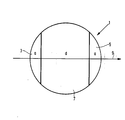
- the figure shows a spherical lens 1 in section with two domes 3, 5 made of magneto-optically active iron-garnet material and a spherical part 7 between the domes 3, 5 made of non-magnetic garnet material.
- the arrow 9 denotes the direction of the preferred magnetization of the magnetic material of the spheres 3 and 5.
- a indicates the maximum layer thickness of the domes 3 and 5, with d the layer thickness of the spherical part 7 lying between the domes is designated.
- the ' ball lens 1 can be arranged in a known manner - (compare, for example, Electronics Letters 18 (1982), pages 1026 to 1028) in an optical communication system in the beam path of a laser diode / single-mode waveguide, and there acts as a focusing optical isolator in cooperation with one a polarizer arranged between the spherical lens and the single-mode waveguide and a magnetization device, the magnetic field of which penetrates the spherical caps 3 and 5 in the direction of propagation of the light and effects the saturation magnetization.
Abstract
Fokussierende, justierbare Vorrichtung zum Drehen der Polarisationsebene linear polarisierten Lichtes in Form einer unter Verwendung von in Durchstrahlungsrichtung (9) vorzugsmagnetisiertem magnetischem Kristallmaterial hergestellten Kugellinse (1), wobei die Kugellinse (1) aus zwei Kalotten (3, 5) mit parallel zueinander und senkrecht zur Durchstrahlungsrichtung des Lichtes ausgerichteten Grundflächen aus magnetischem Granatmaterial mit einem zwischen den Kalotten befindlichen Kugelteil (7) aus optisch transparentem, nichtmagnetischem Granatmaterial besteht.Focusing, adjustable device for rotating the plane of polarization of linearly polarized light in the form of a spherical lens (1) produced using magnetic crystal material which is preferably magnetized in the direction of radiation (9), the spherical lens (1) consisting of two domes (3, 5) with parallel to one another and perpendicular Base surfaces aligned with the direction of radiation of the light made of magnetic garnet material with a spherical part (7) located between the domes made of optically transparent, non-magnetic garnet material.
Description
Die Erfindung betrifft eine Vorrichtung zum Drehen der Polarisationsebene linear polarisierten Lichtes in Form einer unter Verwendung von in Durchstrahlungsrichtung vorzugsmagnetisiertem magnetischem Kristallmaterial hergestellten Kugellinse.The invention relates to a device for rotating the plane of polarization of linearly polarized light in the form of a spherical lens produced using magnetic crystal material which is preferably magnetized in the direction of radiation.
Die Erfindung bezieht sich weiter auf ein Verfahren zur Herstellung einer derartigen Vorrichtung und auf ihre Verwendung.The invention further relates to a method for producing such a device and to its use.
Vorrichtungen zum Drehen der Polarisationsebene linear polarisierten Lichtes aus magnetischem Kristallmaterial werden allgemein als Faraday-Rotatoren bezeichnet.Devices for rotating the plane of polarization of linearly polarized light from magnetic crystal material are generally referred to as Faraday rotators.
In optischen Kommunikationssystemen, die mit optischen Monomode-Wellenleitem und einer Lichtquelle, z.B. einer Laserdiode, arbeiten, sind passive Bauteile erforderlich wie zum Beispiel Linsen zur Fokussierung des eingestrahlten Lichtes oder zum Beispiel unter Verwendung eines Faraday-Rotators aufgebaute optische Isolatoren, die das Licht nur in einer Richtung passieren lassen, während sie die entgegengesetzte Richtung optisch sperren. Solche Isolatoren werden dazu eingesetzt, um die Lichtquelle, z.B. einen Laser, vor Störreflexionen aus dem angeschlossenen optischen System zu - schützen.In optical communication systems using single-mode optical waveguides and a light source, e.g. a laser diode, passive components are required, such as lenses for focusing the incident light or, for example, optical isolators constructed using a Faraday rotator, which allow the light to pass in one direction only while optically blocking the opposite direction. Such isolators are used to isolate the light source, e.g. a laser to protect against interfering reflections from the connected optical system.
Die vorliegende Erfindung betrifft die Kombination zweier für den Aufbau eines optischen Kommunikationssystems mit Monomode-Wellenleiter und einer Lichtquelle in Form von zum Beispiel einer Laserdiode neben anderen eingesetzter passiver Bauteile, nämlich eine Kombination aus fokussierender Kugellinse und Faraday-Rotator für einen optischen Isolator.The present invention relates to the combination of two passive components used for the construction of an optical communication system with a single-mode waveguide and a light source in the form of, for example, a laser diode, namely a combination of a focusing spherical lens and a Faraday rotator for an optical isolator.
Aus Electronics Letters 18 (1982), Nr. 24, Seiten 1026 bis 1028, ist eine Kombination dieser Wirkungsweisen in einem Bauteil bekannt, hier wird eine Kugellinse aus Yttrium-Eisen-Granat (YIG) nicht nur als Faraday-Rotator, sondern auch als Kopplungslinse in einem optischen Kommunikationssystem vorgeschlagen.From Electronics Letters 18 (1982), No. 24, pages 1026 to 1028, a combination of these modes of action is known in one component, here a ball lens made of yttrium iron garnet (YIG) is not only used as a Faraday rotator, but also as Coupling lens proposed in an optical communication system.
Kugellinsen aus YIG können nur unter relativ hohem Kostenaufwand hergestellt werden, da zunächst größere Einkristalle gezüchtet werden müssen, aus denen dann Kugeln geschliffen werden. Ein weiterer Nachteil ist, daß Yttrium-Eisen-Granat eine relativ geringe Faraday-Drehung hat; eine Kugellinse, die z.B. für Strahlung einer Wellenlänge = 1,3u.m eingesetzt werden soll, verlangt einen Kugeldurchmesser von 2,1 mm und ist damit an die Abmessungen von derzeit benutzten optischen Wellenleitem nur unter erhöhtem Aufwand anpassbar. Ein weiterer Nachteil ist, daß zur Sättigungsmagnetisierung von YIG ein relativ hohes Magnetfeld erforderlich ist.Ball lenses made from YIG can only be produced at relatively high cost, since larger single crystals first have to be grown, from which balls are then ground. Another disadvantage is that yttrium iron garnet has a relatively low Faraday rotation; a spherical lens, e.g. to be used for radiation of a wavelength = 1.3µ.m requires a spherical diameter of 2.1 mm and can therefore only be adapted to the dimensions of optical waveguides currently used with increased effort. Another disadvantage is that a relatively high magnetic field is required to saturate YIG.
Faraday-Rotatoren aus magnetischem Granat- material wie z.B. Yttrium-Eisen-Granat Y3(Ga.Fe)5O12 oder aus Wismutsubstituiertem Seltenerdmetall-Eisen-Granat, z.B. (Gd,Bi)3(Ga,Fe,At)5O12 zeichnen sich durch eine hohe Faraday-Rotation eF(O/cm) bei gleichzeitig geringen optischen Verlusten im nahen lnfrarotspektralbereich aus, wobei die Faraday-Rotation bei Wismut-substituierten Eisen-Granaten erheblich größer ist als die von YIG (hierzu wird z.B. verwiesen auf G. Winkler, Magnetic Gamets, Vieweg, Braunschweig 1981, Seite 253 und folgende). Nachteilig an diesen Kristallen ist jedoch, daß ihre Faraday-Rotation infolge der Dispersion abhängig von der Wellenlänge des eingestrahlten Lichtes ist. Dies bedeutet z.B. für einen Isolator, daß die Sperrdämpfung, also die Fähigkeit, Störreflexionen aus einem optischen System zu unterdrücken, wellenlängenabhängig ist. Wird eine hohe Sperrdämpfung verlangt, so kann die Wellenlänge nur relativ wenig variiert werden. Der Faraday-Rotator und damit auch der mit ihm aufgebaute optische Isolator können daher nur in einem Spektralbereich geringer Bandbreite eingesetzt werden. Da der Spektralbereich im nahen Infrarot von etwa 0,8 bis 1,6um für die optische Datenübertragung mit Hilfe von optischen Wellenleitem eine erhebliche Bedeutung erlangt hat, ist dies ein besonders gravierender Nachteil.Faraday rotators made of magnetic garnet material such as yttrium iron garnet Y 3 (Ga.Fe) 5 O 12 or bismuth-substituted rare earth metal iron garnet, eg (Gd, Bi) 3 (Ga, Fe, At) 5 O 12 are characterized by a high Faraday rotation e F ( O / cm) with at the same time low optical losses in the near infrared spectral range, the Faraday rotation in bismuth-substituted iron garnets being considerably larger than that of YIG (reference is made to this for example on G. Winkler, Magnetic Gamets, Vieweg, Braunschweig 1981, page 253 and following). A disadvantage of these crystals, however, is that their Faraday rotation due to the dispersion is dependent on the wavelength of the incident light. For an isolator, for example, this means that the blocking attenuation, ie the ability to suppress interference reflections from an optical system, is dependent on the wavelength. If high blocking attenuation is required, the wavelength can only be varied relatively little. The Faraday rotator and thus also the optical isolator constructed with it can therefore only be used in a spectral range of small bandwidth. Since the spectral range in the near infrared of approximately 0.8 to 1.6 .mu.m has gained considerable importance for optical data transmission with the aid of optical waveguides, this is a particularly serious disadvantage.
Der Erfindung liegt die Aufgabe zugrunde, eine Vorrichtung der eingangs genannten Art zu - schaffen, deren Faraday-Rotation im Wellenlängenbereich des nahen Infrarot (1,1≦ λ ≦ 1,6) auf die Lichtwellenlänge einstellbar ist, die kostengünstig herzustellen ist und die in ihren Abmessungen gut an die Abmessungen der an sie anzukoppelnden optischen Wellenleiter anpaßbar ist.The invention has for its object to provide a device of the type mentioned, the Faraday rotation in the wavelength range of the near infrared (1.1 ≦ λ ≦ 1.6) is adjustable to the light wavelength, which is inexpensive to manufacture and which in their dimensions can be adapted well to the dimensions of the optical waveguides to be coupled to them.
Diese Aufgabe wird gemäß der Erfindung dadurch gelöst, daß die Kugellinse aus zwei Kalotten mit parallel zueinander und senkrecht zur Durchstrahlungsrichtung des Lichtes ausgerichteten Grundflächen aus magnetischem Granatmaterial mit einem zwischen den Kalotten befindlichen Kugelteil aus optisch transparentem, nichtmagnetischem Granatmaterial besteht.This object is achieved according to the invention in that the spherical lens consists of two domes with bases parallel to one another and perpendicular to the direction of radiation of the light made of magnetic garnet material with a spherical part between the domes made of optically transparent, non-magnetic garnet material.
Ein Verfahren zur Herstellung einer solchen Vorrichtung ist dadurch gekennzeichnet, daß auf den Hauptflächen eines Substrates aus optisch transparentem, nichtmagnetischem Granatmaterial epitaktisch Schichten jeweils gleicher Schichtdicke aus magnetischem Granatmaterial abgeschieden werden, daß das beschichtete Substrat in Würfel zersägt wird und daß die Würfel zu Kugeln geschliffen werden.A method for producing such a device is characterized in that epitaxially layers of the same layer thickness are formed on the main surfaces of a substrate made of optically transparent, non-magnetic garnet material be deposited from magnetic garnet material, that the coated substrate is sawn into cubes and that the cubes are ground into spheres.
Nach vorteilhaften weiteren Ausgestaltungen der Erfindung bestehen die Kalotten aus vorzugsweise Wismut-dotiertem Seltenerdmetall-Eisen-Granat.According to advantageous further refinements of the invention, the domes consist of preferably bismuth-doped rare earth metal iron garnet.
Vorzugsweise bestehen die Kalotten aus Seltenerdmetall-Eisen-Granat der allgemeinen Formel
(Gd,Bi)3(Fe,Ga,Al)5O12.The domes preferably consist of rare earth metal iron garnet of the general formula
(Gd, Bi) 3 (Fe, Ga, Al) 5 O 12 .
Nach einer weiteren vorteilhaften Ausgestaltung der Erfindung besteht der zwischen den Kalotten befindliche Kugelteil aus nichtmagnetischem Granatmaterial, dessen Zusammensetzung der Formel entspricht (A,B)3(Ga,C,D)5O12 mit
- A = Gd und/oder Sm und/oder Y
- B,C = Ca und/oder Sr und/oder Mg
- D = Zr und/oder Sn.
- A = Gd and / or Sm and / or Y
- B, C = Ca and / or Sr and / or Mg
- D = Zr and / or Sn.
Vorzugsweise besteht der zwischen den Kalotten befindliche Kugelteil aus nichtmagnetischem Granatmaterial entsprechend der Formel (Gd,Ca)3-(Ga,Mg,Zr)5O12.The spherical part located between the spheres preferably consists of non-magnetic garnet material corresponding to the formula (Gd, Ca) 3 - (Ga, Mg, Zr) 5 O 12 .
Nach einer weiteren vorteilhaften Ausgestaltung der Erfindung haben die Kalotten eine solche maximale Gesamtschichtdicke, die ausreicht, die Polarisationsebene des eingestrahlten Lichtes um mehr als 45° zu drehen.According to a further advantageous embodiment of the invention, the domes have a maximum total layer thickness which is sufficient to rotate the plane of polarization of the incident light by more than 45 °.
Die mit der Erfindung erzielten Vorteile bestehen insbesondere darin, daß ein fokussierender Faraday-Rotator, der für den Aufbau eines Faraday-Isolators eingesetzt werden kann, geschaffen ist, der justierbar, also auf unterschiedliche Wellenlängerr eingestrahlten Lichtes einstellbar ist.The advantages achieved by the invention are, in particular, that a focusing Faraday rotator, which can be used for the construction of a Faraday isolator, is created, which is adjustable, that is, adjustable to different wavelengths of light irradiated.
Dadurch, daß das magneto-optisch wirksame Material in Form von Epitaxieschichten eingesetzt wird, kann der erfindungsgemäße Faraday-Rotator in Form einer Kugellinse auch außerordentlich kostengünstig hergestellt werden. 0.Because the magneto-optically active material is used in the form of epitaxial layers, the Faraday rotator according to the invention in the form of a spherical lens can also be produced extremely inexpensively. 0.
Ein weiterer Vorteil ist, daß infolge der Verwendung von Wismut-dotiertem Eisen-Granat, der eine gegenüber z.B. YIG erhöhte Faraday-Drehung hat, relativ kleine Abmessungen, die gut zu den Abmessungen der anzukoppelnden optischen Wellenleiter passen, für den vorliegenden Faraday-Rotator gewählt werden können.Another advantage is that due to the use of bismuth-doped iron garnet, which is one compared to e.g. YIG increased Faraday rotation has relatively small dimensions, which fit well with the dimensions of the optical waveguides to be coupled, can be chosen for the present Faraday rotator.
Anhand der Zeichnung wird ein Ausführungsbeispiel der Erfindung beschrieben und in ihrer Wirkungsweise erläutert.An exemplary embodiment of the invention is described with reference to the drawing and its operation is explained.
Die Figur zeigt eine Kugellinse 1 im Schnitt mit zwei Kalotten 3,5 aus magneto-optisch wirksamem Eisen-Granat-material und einem zwischen den Kalotten 3,5 befindlichen Kugelteil 7 aus nichtmagnetischem Granatmaterial. Der Pfeil 9 bezeichnet die Richtung der Vorzugsmagnetisierung des magnetischen Materials der Kalotten 3 und 5.The figure shows a spherical lens 1 in section with two domes 3, 5 made of magneto-optically active iron-garnet material and a spherical part 7 between the domes 3, 5 made of non-magnetic garnet material. The arrow 9 denotes the direction of the preferred magnetization of the magnetic material of the spheres 3 and 5.
a gibt die maximale Schichtdicke der Kalotten 3 und 5 an, mit d ist die Schichtdicke des zwischen den Kalotten liegenden Kugelteils 7 bezeichnet.a indicates the maximum layer thickness of the domes 3 and 5, with d the layer thickness of the spherical part 7 lying between the domes is designated.
Die' Kugellinse 1 kann auf bekannte Weise - (vergleiche z.B. Electronics Letters 18 (1982), Seiten 1026 bis 1028) in einem optischen Kommunikationssystem im Strahlengang einer Laserdiode/Monomode-Wellenleiter angeordnet werden, und wirkt dort als fokussierender optischer Isolator unter Zusammenwirken mit einem zwischen der Kugellinse und dem Monomode-Wellenleiter angeordneten Polarisator und einer Magnetisierungseinrichtung, deren magnetisches Feld die Kalotten 3 und 5 in Ausbreitungsrichtung des Lichtes durchsetzt und die Sättigungsmagnetisierung bewirkt. In Richtung der größten Dicke a der Kalotten 3 und 5 liegt eine wachstumsinduzierte magnetische Anisotropie vor. Durch geringes Verdrehen dieser Richtung aus der optischen Achse des Systems Laserdiode/Monomode-Wellenleiter wird die effektive Dicke des die Kalotten bildenden magnetischen Materials und damit die magnetooptische Drehung reduziert und damit an die Wellenlänge des eingestrahlten Lichtes angepaßt.The ' ball lens 1 can be arranged in a known manner - (compare, for example, Electronics Letters 18 (1982), pages 1026 to 1028) in an optical communication system in the beam path of a laser diode / single-mode waveguide, and there acts as a focusing optical isolator in cooperation with one a polarizer arranged between the spherical lens and the single-mode waveguide and a magnetization device, the magnetic field of which penetrates the spherical caps 3 and 5 in the direction of propagation of the light and effects the saturation magnetization. There is a growth-induced magnetic anisotropy in the direction of the greatest thickness a of the domes 3 and 5. By turning this direction slightly from the optical axis of the laser diode / single-mode waveguide system, the effective thickness of the magnetic material forming the domes and thus the magneto-optical rotation is reduced and thus adapted to the wavelength of the incident light.
Die Kugellinse 1 gemäß der Figur wird wie folgt hergestellt:
- Aus einer Schmelze der Zusammensetzungund einer Sättigungstemperatur Ts von 819°C wurden nach dem aus Joumal of Crystal Growth 64 - (1983) Seiten 275 bis 284 bekannten Flüssigphasenepitaxieverfahren auf horizontal gehalterten, 0,55 mm dicken (111-orientierten (Gd,Ca)3(Ga,Mg,Zr)5O12-Einkristallschieben eines Durchmessers von 30 mm als Substrat beidseitig Schichten einer Zusammensetzung entsprechend der Formel

- (Gd,Bi)3(Fe,Ga,Al)5O12 mit einer Schichtdicke von jeweils 160u.m epitaktisch angebracht. Es ist hierbei anzumerken, daß, obwohl ein Lösungsmittel in Form von PbO und B2O3 eingesetzt wurde, der Bor-und Bleieinbau in die anwachsende Schicht so gering ist, daß er zu vernachlässigen ist. Aus den beschichteten Substraten wurden Würfel von 0,87 mm Kantenlänge gesägt, in exzentrisch rotierenden Schleiftöpfen gerundet und in Käfigen zwischen gekreuzt rotierenden Scheiben poliert. Die resultierenden Kugeln hatten einen Gesamtdurchmesser D = d+2a von 0,8 mm mit einer maximalen Schichtdicke der Kalotten 3 und 5 a = 0,125 mm - (vergleiche Figur). Die Faraday-Rotation betrug bei einer Wellenlänge λ = 1,3µm 1,9 x 10³ °/cm. Die Sättigungsmagnetisierung Ms betrug 17 mT (bei 20°C).
- From a melt of the composition and a saturation temperature T s of 819 ° C were according to the liquid phase epitaxy method known from Joumal of Crystal Growth 64 - (1983) pages 275 to 284 on horizontally held, 0.55 mm thick (111-oriented (Gd, Ca) 3 (Ga, Mg, Zr) 5 O 12 single crystal slides with a diameter of 30 mm as the substrate, layers on both sides of a composition according to the formula
- (Gd, Bi) 3 (Fe, Ga, Al) 5 O 12 with a layer thickness of 160u.m each epitaxially applied. It should be noted here that although a solvent in the form of PbO and B 2 O 3 was used, the boron and lead incorporation into the growing layer is so small that it can be neglected. Cubes with an edge length of 0.87 mm were sawn from the coated substrates, rounded in eccentrically rotating cup wheels and polished in cages between crossed rotating disks. The resulting spheres had a total diameter D = d + 2a of 0.8 mm with a maximum layer thickness of the domes 3 and 5 a = 0.125 mm - (see figure). The Faraday rotation was 1.9 x 10 3 ° / cm at a wavelength λ = 1.3 µm. The saturation magnetization M s was 17 mT (at 20 ° C).
Claims (17)
, dadurch gekennzeichnet.
daß die Kugellinse (1) aus zwei Kalotten (3,5) mit parallel zueinander und senkrecht zur Durchstrahlungsrichtung des Lichtes ausgerichteten Grundflächen aus magnetischem Granatmaterial mit einem zwischen den Kalotten befindlichen Kugelteil (7) aus optisch transparentem, nichtmagnetischem Granatmaterial besteht.1. Device for rotating the plane of polarization of linearly polarized light in the form of a spherical lens produced using magnetic crystal material which is preferably magnetized in the direction of radiation,
, characterized.
that the ball lens (1) consists of two domes (3, 5) with bases parallel to one another and perpendicular to the direction of radiation of the light made of magnetic garnet material with a spherical part (7) located between the domes made of optically transparent, non-magnetic garnet material.
dadurch gekennzeichnet.
daß die Kalotten (3,5) aus Seltenerdmetall-Esen-Granat bestehen.2. Device according to claim 1,
characterized.
that the calottes (3,5) consist of rare earth metal garnet.
dadurch gekennzeichnet,
daß die Kalotten (3,5) aus Wismut-substituiertem Seltenerdmetall-Esen-Granat bestehen.3. Device according to claim 2,
characterized,
that the calottes (3,5) consist of bismuth-substituted rare earth metal garnet.
dadurch aekennzeichnet.
daß die Kalotten (3,5) aus Seltenerdmetall-Eisen-Granat entsprechend der allgemeinen Formel
(Gd,Bi)3(Fe,Ga,Al)5O12 bestehen.4. The device according to claim 3,
thereby marked.
that the calottes (3,5) made of rare earth iron garnet according to the general formula
(Gd, Bi) 3 (Fe, Ga, Al) 5 O 12 exist.
dadurch gekennzeichnet,
daß der zwischen den Kalotten (3,5) befindliche Kugelteil (7) aus Granatmaterial besteht, dessen Zusammensetzung der Formel entspricht (A,B)3-(Ga,C,D)5O12
mit A = Gd und/oder Sm und/oder Y
characterized,
that the spherical part (7) located between the domes (3, 5) consists of garnet material, the composition of which corresponds to the formula (A, B) 3 - (Ga, C, D) 5 O 12
with A = Gd and / or Sm and / or Y
dadurch gekennzeichnet,
daß der zwischen den Kalotten (3,5) befindliche Kugelteil (7) aus Granatmaterial entsprechend der allgemeinen Formel (Gd,Ca)3(Ga,Mg,Zr)5O12 besteht.6. The device according to claim 5,
characterized,
that the spherical part (7) located between the domes (3, 5) consists of garnet material according to the general formula (Gd, Ca) 3 (Ga, Mg, Zr) 5 O 12 .
dadurch gekennzeichnet.
daß die Kalotten (3,5) aus Seltenerdmetall-Eisen-Granat entsprechend der Formel (Gd,Bi)3(Fe,Ga,Al)-5O12) und der zwischen den Kalotten befindliche Kugelteil (7) aus Granatmaterial entsprechend der Formel
(Gd,Ca)3(Ga,Mg,Zr)5O12 bestehen.7. Device according to claims 1, 4 and 6,
characterized.
that the domes (3,5) made of rare earth iron garnet according to the formula (Gd, Bi) 3 (Fe, Ga, Al) - 5 O 12 ) and the spherical part (7) between the domes made of garnet material according to the formula
(Gd, Ca) 3 (Ga, Mg, Zr) 5 O 12 .
dadurch aekennzeichnet.
daß die Kalotten (3,5) eine solche maximale Gesamtschichtdicke haben, die ausreicht, die Polarisationsebene des eingestrahlten Lichtes um mehr als 45 zu drehen.8. Device according to one of the preceding claims,
thereby marked.
that the domes (3,5) have such a maximum total layer thickness that is sufficient to rotate the plane of polarization of the incident light by more than 45.
daß auf den Hauptflächen eines Substrates aus optisch transparentem, nichtmagnetischem Granat- material epitaktisch Schichten jeweils gleicher Schichtdicke aus magnetischem Granatmaterial abgeschieden werden, daß das beschichtete Substrat in Würfel zersägt wird und daß die Würfel zu Kugeln geschliffen werden.9. A method for producing a device according to claims 1 to 8, characterized.
that epitaxially layers of the same layer thickness made of magnetic garnet material are deposited on the main surfaces of a substrate made of optically transparent, non-magnetic garnet material, that the coated substrate is sawn into cubes and that the cubes are ground into balls.
dadurch gekennzeichnet.
daß auf dem Substrat Schichten aus Seltenerdmetall-Eisen-Granat abgeschieden werden.10. The method according to claim 9,
characterized.
that layers of rare earth iron garnet are deposited on the substrate.
dadurch aekennzeichnet.
daß Wismut-substituierte Schichten aus Seltenerdmetall-Eisen-Granat abgeschieden werden.11. The method according to claim 10,
thereby marked.
that bismuth-substituted layers of rare earth iron garnet are deposited.
dadurch gekennzeichnet,
daß Schichten einer Zusammensetzung entsprechend der Formel
(Gd,Bi)3(Fe,Ga,Al)5O12 abgeschieden werden.12. The method according to claim 11,
characterized,
that layers of a composition according to the formula
(Gd, Bi) 3 (Fe, Ga, Al) 5 O 12 are deposited.
dadurch gekennzeichnet,
daß die Schichten aus magnetischem Granatmaterial auf einem Substrat aus Granatmaterial entsprechend der allgemeinen Formel (A,B)3(Ga,C,D)5O12
mit A = Gd und/oder Sm und/oder Y
characterized,
that the layers of magnetic garnet material on a substrate made of garnet material according to the general formula (A, B) 3 (Ga, C, D) 5 O 12
with A = Gd and / or Sm and / or Y
dadurch gekennzeichnet,
daß die Schichten auf einem Substrat abgeschieden werden, dessen Zusammensetzung der Formel (Gd,Ca)3(Ga,Mg,Zr)5O12 entspricht.14. The method according to claim 13,
characterized,
that the layers are deposited on a substrate whose composition corresponds to the formula (Gd, Ca) 3 (Ga, Mg, Zr) 5 O 12 .
dadurch gekennzeichnet,
daß auf der unteren und der oberen Hauptfläche eines Substrates, dessen Zusammensetzung der Formel
characterized,
that on the lower and the upper main surface of a substrate, the composition of the formula
dadurch aekennzeichnet.
daß die Schichtdicke der epitaktisch abgeschiedenen magneto-optisch wirksamen Schichten so gewählt wird, daß die maximale Gesamtschichtdicke der nach dem Schleifprozeß erhaltenen Kalotten ausreicht, die Polarisationsebene des eingestrahlten Lichtes um mehr als 45° zu drehen.16. The method according to claims 9 to 15,
thereby marked.
that the layer thickness of the epitaxially deposited magneto-optically active layers is chosen so that the maximum total layer thickness of the spheres obtained after the grinding process is sufficient, the polarization plane of the radiated light by more than 45 °.
Applications Claiming Priority (2)
| Application Number | Priority Date | Filing Date | Title |
|---|---|---|---|
| DE19853517785 DE3517785A1 (en) | 1985-05-17 | 1985-05-17 | DEVICE FOR ROTATING THE POLARIZATION LEVEL LINEAR POLARIZED LIGHTS AND METHOD FOR THE PRODUCTION THEREOF |
| DE3517785 | 1985-05-17 |
Publications (2)
| Publication Number | Publication Date |
|---|---|
| EP0202709A2 true EP0202709A2 (en) | 1986-11-26 |
| EP0202709A3 EP0202709A3 (en) | 1988-07-27 |
Family
ID=6270977
Family Applications (1)
| Application Number | Title | Priority Date | Filing Date |
|---|---|---|---|
| EP86200794A Withdrawn EP0202709A3 (en) | 1985-05-17 | 1986-05-06 | Device for rotating the polarization plane of linearly polarized light, and method for making the same |
Country Status (4)
| Country | Link |
|---|---|
| US (1) | US4735489A (en) |
| EP (1) | EP0202709A3 (en) |
| JP (1) | JPS61264301A (en) |
| DE (1) | DE3517785A1 (en) |
Cited By (2)
| Publication number | Priority date | Publication date | Assignee | Title |
|---|---|---|---|---|
| EP0275068A2 (en) * | 1987-01-14 | 1988-07-20 | Siemens Aktiengesellschaft | Optical arrangement for converting divergently emitted polarized radiation of a semiconductor-laser into convergent radiation without feedback |
| AU605029B2 (en) * | 1988-03-25 | 1991-01-03 | Telstra Corporation Limited | Magneto-optic device |
Families Citing this family (8)
| Publication number | Priority date | Publication date | Assignee | Title |
|---|---|---|---|---|
| US4774615A (en) * | 1987-02-17 | 1988-09-27 | Eastman Kodak Company | Magneto-optic read-out method and apparatus with polarization correction means |
| US4818080A (en) * | 1987-11-05 | 1989-04-04 | General Electric Company | Monolithic faraday optical switch |
| US5009477A (en) * | 1989-05-12 | 1991-04-23 | At&T Bell Laboratories | Optical interconnect arrangement |
| US5267077A (en) * | 1990-11-05 | 1993-11-30 | At&T Bell Laboratories | Spherical multicomponent optical isolator |
| US5345331A (en) * | 1993-04-13 | 1994-09-06 | At&T Bell Laboratories | Technique for reducing polarization dependent gain in an amplified optical transmission system |
| US6871023B2 (en) * | 2001-12-03 | 2005-03-22 | The Boeing Company | Spread polarization transmitter and associated system and method of operation |
| JP2005266182A (en) * | 2004-03-18 | 2005-09-29 | Nec Tokin Corp | Optical isolator |
| CN100346195C (en) * | 2005-04-19 | 2007-10-31 | 浙江大学 | 45 deg. Faraday rotator without adding bias magnetic field |
Citations (2)
| Publication number | Priority date | Publication date | Assignee | Title |
|---|---|---|---|---|
| US3989352A (en) * | 1973-04-26 | 1976-11-02 | U.S. Philips Corporation | Bismuth substituted rare earth garnets as magneto-optic materials exhibiting magnetic circular dichroism |
| US4375910A (en) * | 1979-09-25 | 1983-03-08 | Nippon Electric Co., Ltd. | Optical isolator |
Family Cites Families (6)
| Publication number | Priority date | Publication date | Assignee | Title |
|---|---|---|---|---|
| US3784281A (en) * | 1973-03-06 | 1974-01-08 | Bbc Brown Boveri & Cie | Ferrimagnetic garnet corrected for temperature dependence of the faraday effect and method for making the same |
| FR2356965A1 (en) * | 1976-07-02 | 1978-01-27 | Thomson Csf | MAGNETO-OPTICAL DEFLECTOR |
| US4082424A (en) * | 1976-07-28 | 1978-04-04 | Sperry Rand Corporation | Integrated optic device |
| US4304461A (en) * | 1977-07-19 | 1981-12-08 | Plessey Handel Und Investments Ag. | Optical fibre connectors |
| JPS58139082A (en) * | 1982-02-15 | 1983-08-18 | Hitachi Ltd | Magnetic field measuring apparatus |
| US4544239A (en) * | 1983-03-16 | 1985-10-01 | Litton Systems, Inc. | Compressed bismuth-containing garnet films of replicable low anisotropy field value and devices utilizing same |
-
1985
- 1985-05-17 DE DE19853517785 patent/DE3517785A1/en not_active Withdrawn
-
1986
- 1986-05-06 EP EP86200794A patent/EP0202709A3/en not_active Withdrawn
- 1986-05-12 US US06/861,956 patent/US4735489A/en not_active Expired - Fee Related
- 1986-05-14 JP JP61108717A patent/JPS61264301A/en active Pending
Patent Citations (2)
| Publication number | Priority date | Publication date | Assignee | Title |
|---|---|---|---|---|
| US3989352A (en) * | 1973-04-26 | 1976-11-02 | U.S. Philips Corporation | Bismuth substituted rare earth garnets as magneto-optic materials exhibiting magnetic circular dichroism |
| US4375910A (en) * | 1979-09-25 | 1983-03-08 | Nippon Electric Co., Ltd. | Optical isolator |
Non-Patent Citations (3)
| Title |
|---|
| Applied Optics, Band 24, Nr. 7, 1. April 1985 K. SHIRAISHI; "Fibre-Embedded Micro-Faraday Rotator for the Infrared" seiten 951-953 kapitel I, II; fig. 1 * * |
| Electronics Letters, Band 18, Nr. 24, 25. November 1982 T. SUGIE et al. "Nonreciprocal Circuit for Laser-Diode-to-Single-Mode-Fibre Coupling Employing a Yig Sphere" seiten 1026-1028 * Zusammenfassung; seite 1027, linke spalte; fig. 1 * * |
| Soviet Inventions Illustrated, Sektion E1, Woche D 52, 10. Februar 1982 Derwent Publications Ltd., London, V 07 * SU 813-351 (Imas YA A) * * |
Cited By (3)
| Publication number | Priority date | Publication date | Assignee | Title |
|---|---|---|---|---|
| EP0275068A2 (en) * | 1987-01-14 | 1988-07-20 | Siemens Aktiengesellschaft | Optical arrangement for converting divergently emitted polarized radiation of a semiconductor-laser into convergent radiation without feedback |
| EP0275068B1 (en) * | 1987-01-14 | 1992-07-29 | Siemens Aktiengesellschaft | Optical arrangement for converting divergently emitted polarized radiation of a semiconductor-laser into convergent radiation without feedback |
| AU605029B2 (en) * | 1988-03-25 | 1991-01-03 | Telstra Corporation Limited | Magneto-optic device |
Also Published As
| Publication number | Publication date |
|---|---|
| DE3517785A1 (en) | 1986-11-20 |
| JPS61264301A (en) | 1986-11-22 |
| US4735489A (en) | 1988-04-05 |
| EP0202709A3 (en) | 1988-07-27 |
Similar Documents
| Publication | Publication Date | Title |
|---|---|---|
| DE2919590C2 (en) | ||
| EP0352844B1 (en) | Optical isolator, circulator, switch or similar device with a Faraday rotator | |
| DE3610473C2 (en) | ||
| DE2931474A1 (en) | NON-RECIPE OPTICAL DEVICE | |
| DE2347065A1 (en) | DEVICE WITH A MAGNETO-OPTIC MODULATOR | |
| DE19541852A1 (en) | Faraday rotator and optical separator with one | |
| DE3904660A1 (en) | PLANAR OPTICAL ISOLATOR | |
| EP0202709A2 (en) | Device for rotating the polarization plane of linearly polarized light, and method for making the same | |
| DE2607793A1 (en) | MAGNETO-OPTICAL LIGHT DEFLECTOR | |
| DE69928152T2 (en) | Faraday rotator | |
| EP0142895A2 (en) | Magneto-optic waveguide structure with artificial optical anisotropy | |
| DE2843327C2 (en) | ||
| EP0199414A2 (en) | Plane optical waveguide and process for its production | |
| DE2733735A1 (en) | INTEGRATED OPTICAL DEVICE | |
| DE2853149A1 (en) | OPTICAL BRANCHING WITH ELECTRICAL CONTROL AND APPLICATION OF THE SAME ON FIBER OPTIC TRANSMISSION DEVICES | |
| EP0275068B1 (en) | Optical arrangement for converting divergently emitted polarized radiation of a semiconductor-laser into convergent radiation without feedback | |
| DE3506266A1 (en) | METHOD AND DEVICE FOR CONTINUOUSLY STEERING A MILLIMETER WAVELENGTH RADIATION RADIATION | |
| DE60004259T2 (en) | OPTICAL CIRCUIT ELEMENT AND ITS MANUFACTURING METHOD | |
| EP0175425B1 (en) | Planar optical wave guide and method for its fabrication | |
| DE3011663A1 (en) | Optical fibre polarisation device - has crystal block with edge face in contact with polished surface of optical conductor | |
| DE3426138C2 (en) | Optical one-way line | |
| DE3939723C1 (en) | Optical or opto-electronic coupling - uses spherical lens received in frusto-pyramidal recess of one part and groove of other part | |
| DE112021003260T5 (en) | MAGNETIC CIRCLE, FARADAY ROTATOR AND MAGNETO-OPTICAL DEVICE | |
| DE3026573C2 (en) | Process for growing a magneto-optical bismuth-rare earth-iron garnet crystal | |
| DE112019002973T5 (en) | Faraday rotator and magneto-optical element |
Legal Events
| Date | Code | Title | Description |
|---|---|---|---|
| PUAI | Public reference made under article 153(3) epc to a published international application that has entered the european phase |
Free format text: ORIGINAL CODE: 0009012 |
|
| AK | Designated contracting states |
Kind code of ref document: A2 Designated state(s): DE FR GB NL SE |
|
| RAP1 | Party data changed (applicant data changed or rights of an application transferred) |
Owner name: N.V. PHILIPS' GLOEILAMPENFABRIEKEN Owner name: PHILIPS PATENTVERWALTUNG GMBH |
|
| PUAL | Search report despatched |
Free format text: ORIGINAL CODE: 0009013 |
|
| AK | Designated contracting states |
Kind code of ref document: A3 Designated state(s): DE FR GB NL SE |
|
| 17P | Request for examination filed |
Effective date: 19890117 |
|
| 17Q | First examination report despatched |
Effective date: 19910226 |
|
| STAA | Information on the status of an ep patent application or granted ep patent |
Free format text: STATUS: THE APPLICATION IS DEEMED TO BE WITHDRAWN |
|
| 18D | Application deemed to be withdrawn |
Effective date: 19911203 |
|
| RIN1 | Information on inventor provided before grant (corrected) |
Inventor name: PASSIG, GERD Inventor name: BARTELS, INSKE Inventor name: TOLKSDORF, WOLFGANG, PROF.DR.DIPL.-CHEM. |