EP0206012A1 - Fluid meter or flow meter - Google Patents
Fluid meter or flow meter Download PDFInfo
- Publication number
- EP0206012A1 EP0206012A1 EP19860107495 EP86107495A EP0206012A1 EP 0206012 A1 EP0206012 A1 EP 0206012A1 EP 19860107495 EP19860107495 EP 19860107495 EP 86107495 A EP86107495 A EP 86107495A EP 0206012 A1 EP0206012 A1 EP 0206012A1
- Authority
- EP
- European Patent Office
- Prior art keywords
- flow meter
- liquid
- measuring chamber
- valve
- opening
- Prior art date
- Legal status (The legal status is an assumption and is not a legal conclusion. Google has not performed a legal analysis and makes no representation as to the accuracy of the status listed.)
- Withdrawn
Links
Images


Classifications
-
- G—PHYSICS
- G01—MEASURING; TESTING
- G01F—MEASURING VOLUME, VOLUME FLOW, MASS FLOW OR LIQUID LEVEL; METERING BY VOLUME
- G01F3/00—Measuring the volume flow of fluids or fluent solid material wherein the fluid passes through the meter in successive and more or less isolated quantities, the meter being driven by the flow
- G01F3/36—Measuring the volume flow of fluids or fluent solid material wherein the fluid passes through the meter in successive and more or less isolated quantities, the meter being driven by the flow with stationary measuring chambers having constant volume during measurement
- G01F3/38—Measuring the volume flow of fluids or fluent solid material wherein the fluid passes through the meter in successive and more or less isolated quantities, the meter being driven by the flow with stationary measuring chambers having constant volume during measurement having only one measuring chamber
-
- G—PHYSICS
- G01—MEASURING; TESTING
- G01F—MEASURING VOLUME, VOLUME FLOW, MASS FLOW OR LIQUID LEVEL; METERING BY VOLUME
- G01F11/00—Apparatus requiring external operation adapted at each repeated and identical operation to measure and separate a predetermined volume of fluid or fluent solid material from a supply or container, without regard to weight, and to deliver it
- G01F11/28—Apparatus requiring external operation adapted at each repeated and identical operation to measure and separate a predetermined volume of fluid or fluent solid material from a supply or container, without regard to weight, and to deliver it with stationary measuring chambers having constant volume during measurement
- G01F11/284—Apparatus requiring external operation adapted at each repeated and identical operation to measure and separate a predetermined volume of fluid or fluent solid material from a supply or container, without regard to weight, and to deliver it with stationary measuring chambers having constant volume during measurement combined with electric level detecting means
Abstract
Description
Die Erfindung betrifft einen Flüssigkeits-Mengenmesser bzw. Durchflußmesser, enthaltend eine allseits geschlossene Meßkammer, eine auf die Flüssigkeitsfüllung in der Meßkammer ansprechende und mindestens bei einem vorgegebenen oberen Füllgrenzwert ein elektrisches oder mechanisches Signal abgebende überwachungseinrichtung, drei in die Meßkammer einmündende Öffnungen, von denen die erste Öffnung mit einem Zulauf für die zu messende Flüssigkeit verbunden ist, die zweite Öffnung unter dem beim oberen Füllgrenzwert gegebenen oberen Flüssigkeitsspiegel angeordnet und an eine durch ihre Mündung die gemessene Flüssigkeit entlassende Ablaufleitung angeschlossen ist und die dritte Öffnung für den Durchtritt von Luft vorgesehen ist, eine mindestens einer der Öffnungen nachgeschaltete, jeweils bei Erreichung des vorgegebenen oberen Flüssigkeitsspiegels umgesteuerte und eine Leerung der Meßkammer bewirkende Ventilanordnung und eine von der überwachungseinrichtung beaufschlagte Auswerteeinrichtung, welche aus der Zahl der aufeinanderfolgenden Meßkammer-Füllungen eine der durchgelaufenen Flüssigkeitsmenge bzw. aus dem Zeitbedarf für eine oder mehrere Meßkammerfüllungen einen dem Durchfluß entsprechenden Wert ermittelt.The invention relates to a liquid flow meter or flow meter, comprising a measuring chamber which is closed on all sides, a monitoring device which responds to the liquid filling in the measuring chamber and emits an electrical or mechanical signal at least at a predetermined upper filling limit value, three openings opening into the measuring chamber, of which the first opening is connected to an inlet for the liquid to be measured, the second opening is arranged below the upper liquid level given at the upper filling limit value and on a discharge line discharging the measured liquid through its mouth is connected and the third opening is provided for the passage of air, at least one of the openings downstream, which is reversed when the predetermined upper liquid level is reached and which empties the measuring chamber, and one from the monitoring device acted upon evaluation device which determines one of the volume of liquid passed through from the number of successive measuring chamber fillings or a value corresponding to the flow from the time required for one or more measuring chamber fillings.
Bei einem derartigen bekannten Durchflußmesser (DE-OS 26 37 681), der vorzugsweise der Überwachung von austretenden menschlichen Körperflüssigkeiten dienen soll, ist die an die zweite Öffnung angeschlossene Ablaufleitung nach unten geführt und die gemessene Flüssigkeit läuft durch deren Mündung frei in einen tiefer als der Durchflußmesser angeordneten Auffangbehälter. Die Ventilanordnung besteht aus einem in dieser Auslaufleitung angeordnetem Elektromagnetventil, das gesteuert von der überwachungseinrichtung und Auswerteeinrichtung öffnet, wenn die Flüssigkeitsfüllung in der Meßkammer einen oberen Füllgrenzwert erreicht und das schließt, wenn durch den Auslauf der Flüssigkeit die Flüssigkeitsfüllung auf einen unteren Füllgrenzwert gesunken ist. Die dritte öffnung der Meßkammer dient deren Entlüftung und steht mit der freien Atmosphäre in Verbindung.In such a known flow meter (DE-OS 26 37 681), which is preferably used to monitor escaping human body fluids, the drain line connected to the second opening is guided downwards and the measured liquid runs freely through its mouth into a deeper than that Flow meter arranged collection container. The valve arrangement consists of a solenoid valve arranged in this outlet line, which, controlled by the monitoring device and evaluation device, opens when the liquid filling in the measuring chamber reaches an upper filling limit value and closes when the liquid filling has dropped to a lower filling limit value due to the liquid outlet. The third opening of the measuring chamber serves to vent it and is connected to the free atmosphere.
In vielen Einsatzfällen, beispielsweise zur Messung oder überwachung der aus einer Gleitringdichtung austretenden Leckage, ist ein tief gelegener Auffangbehälter für die gemessene Flüssigkeit nicht anwendbar, weil der erforderliche Platz nicht geschaffen werden kann oder weil dann die Flüssigkeit aus dem Auffangbehälter mit erheblichem Aufwand wieder auf ein höheres Niveau gefördert werden müßte. Weiterhin liegen Einsatzfälle vor, bei denen die zu messende Flüssigkeit oder der Aufstellungsort für den Mengen- bzw. Durchflußmesser explosionsgefährdet ist. Bei dem bekannten Gerät ist das Elektromagnetventil mit dem Gerät selbst verbunden, bzw. muß zumindest in seiner die Flüssigkeit führenden Ablaufleitung angeordnet sein. Ist die Flüssigkeit explosionsgefährdet, muß daher ein entsprechend aufwendiges, den einschlägigen Sicherheitsbestimmungen genügendes Elektromagnetventil eingesetzt werden und auch dessen Zuleitung entsprechend ausgebildet sein.In many applications, for example for measuring or monitoring the leakage emerging from a mechanical seal, a deep-lying collecting container for the measured liquid cannot be used because the required space cannot be created or because the liquid from the collecting container then re-engages with considerable effort higher level should be promoted. There are also applications in which the liquid to be measured or the installation site for the flow meter or flow meter is at risk of explosion. In the known device, the solenoid valve is connected to the device itself, or at least must be arranged in its drain line carrying the liquid. If the liquid is at risk of explosion, a correspondingly complex solenoid valve that complies with the relevant safety regulations must be used and its supply line must be designed accordingly.
Aufgabe der Erfindung ist es, einen Flüssigkeits-Mengenmesser bzw. Durchflußmesser der eingangs genannten Art so weiterzubilden, daß die zu messende Flüssigkeit auch bei druckloser Zuführung auf einem gegenüber der Zulaufstellung höheren Niveau abgebbar ist und er mit nur geringem Aufwand für höchste Sicherheitsanforderungen auslegbar ist, wenn die zu messende Flüssigkeit bzw. sein Aufstellungsort explosionsgefährdet ist.The object of the invention is to develop a liquid flow meter or flow meter of the type mentioned at the outset in such a way that the liquid to be measured can be dispensed at a higher level than the inlet position even when the supply is unpressurized and it can be designed with very little effort for the highest safety requirements, if the liquid to be measured or its location is potentially explosive.
Diese Aufgabe wird erfindungsgemäß dadurch gelöst, daß die Mündung der Ablaufleitung auf einem über dem oberen Flüssigkeitsspiegel befindlichen Niveau angeordnet ist, daß an die dritte öffnung über eine Speiseleitung eine DruckluftTelle angeschlossen ist und daß die Ventilanordnung im Zuge der Speiseleitung liegt und/oder zwischen der ersten Öffnung und dem Zulauf angeordnet ist.This object is achieved in that the mouth of the drain line is arranged at a level above the upper liquid level, that a compressed air point is connected to the third opening via a feed line and that the valve arrangement lies in the course of the feed line and / or between the first Opening and the inlet is arranged.
Aufgrund dieser Ausbildung wird ein Elektromagnetventil in der die Flüssigkeit führenden Ablaufleitung entbehrlich, da die periodische Entleerung der Flüssigkeitsfüllungen in der Meßkammer durch deren Beaufschlagung mit einem Luftüberdruck erfolgt. Die Steuerung dieses Luft-überdrucks kann dabei entweder ausschliesslich mit mechanischen Mitteln erfolgen, die keine Explosionsgefahr erzeugen, beispielsweise durch Rückschlag-oder Strömungsventile, welche ggf. durch einen Schwimmer in der Meßkammer gesteuert werden. Soweit ein Elektromagnetventil in der die Druckluft zuführenden Speiseleitung angeordnet wird, kommt mit dieses/der zu messenden Flüssigkeit nicht in Berührung und kann auch außerhalb eines explosionsgefährdeten Bereiches angeordnet werden. Die auf der Höhe der Flüssigkeitsfüllung in der Meßkammer ansprechende Überwachungseinrichtung kann preisgünstig explosionssicher dadurch ausgebildet werden, daß_eine eigensichere Bauart gewählt wird, d. h. daß die Energie in ihrem Stromkreis so gering gehalten wird, daß explosionsfähige Gemische nicht gezündet werden können.Because of this design, an electromagnetic valve in the drain line carrying the liquid is dispensed with, since the periodic emptying of the liquid fillings in the measuring chamber takes place by subjecting them to an excess air pressure. The control of this air overpressure can be carried out either exclusively with mechanical means which do not generate any risk of explosion, for example through check or flow valves, which may be controlled by a float in the measuring chamber. If an electromagnetic valve is arranged in the feed line supplying compressed air, it does not come into contact with this / the liquid to be measured and can also be arranged outside an area at risk of explosion. The monitoring device which responds to the level of the liquid filling in the measuring chamber can be inexpensively designed to be explosion-proof in that an intrinsically safe type is selected, ie the energy in its circuit is so low is held that explosive mixtures cannot be ignited.
Weitere Merkmale und Vorteile der Erfindung gehen aus den Unteransprüchen und der nachfolgenden Beschreibung von Ausführungsbeispielen hervor, welche anhand der Zeichnungen erläutert werden und in denen zeigt:
- Fig. 1 einen Schnitt durch eine erste Ausführungsform mit Elektromagnetventil in der Druckluft-Speiseleitung;
- Fig. 2 einen Schnitt durch eine zweite Ausführungsform ohne Elektromagnetventil und
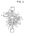
- Fig. 3 eine Modifikation der zweiten Ausführungsform.
- 1 shows a section through a first embodiment with a solenoid valve in the compressed air feed line.
- Fig. 2 shows a section through a second embodiment without a solenoid valve and
- Fig. 3 shows a modification of the second embodiment.
Die in Fig. 1 veranschaulichte erste Ausführungsform enthält einen in seiner Gesamtheit mit 1 bezeichneten Körper,bestehend aus einer hohlzylindrischen Seitenwand 2, einem Deckelteil 3 und einem Bodenteil 4, welche eine zylindrische Meßkammer 5 mit vertikaler Achse 6 umschliessen, in der beweglich ein Schwimmer 7aangeordnet ist, der aus ferromagnetischem Ma-terial, beispielsweise Eisenblech besteht oder entsprechendes Material enthält. In einer in der Längsachse 6 gelegenen Bohrung des Bodenteils 4 ist ein von einem induktiven Näherungsschalter gebildeter Sensor 7b angeordnet. Dieser bildet zusammen mit dem Schwimmer 7a eine überwachungseinrichtung 7, welche bei einem vorgegebenen Abstand des Schwimmers 7a (vgl. die gestrichelte Lage) zum Sensor 7b, die einem bestimmten oberen Füllgrenzwert der Flüssigkeit in der Meßkammer 5 entspricht, ein elektrisches Signal über eine Leitung 9 an eine Auswerteinrichtung 10 abgibt.The first embodiment illustrated in FIG. 1 contains a body designated in its entirety by 1, consisting of a hollow
In die Meßkammer 5 münden insgesamt drei öffnungen 11-13. Die erste öffnung 11 befindet sich im Deckelteil 3 im Bereich der vertikalen Längsachse 6und steht über ein in seiner Gesamtheit mit14abezeichnetes Rückschlagventil mit einem Zulauf 15 in Verbindung, der sich nach oben in eine trichterförmige Auffangschale 16 erweitert, welche die zu messende Flüssigkeit aufnimmt und auch ein gewisses Quantum dieser Flüssigkeit während der später noch erläuterten Entleerungsphase der Meßkammer 5 speichern kann.A total of three openings 11-13 open into the
Die zweite Öffnung ist im Bodenteil 4 ausgebildet und an eine Ablaufleitung 17 angeschlossen, welche nach oben geführt ist, so daß sich ihre Mündung 17 a, unterhalb der sich ein Auffangbehälter 18 für die gemessene Flüssigkeit befindet, höher als der obere Flüssigkeitsspiegel in der Meßkammer 5 befindet. wie er durch den oberen Füllgrenzwert vorgegeben ist, bei welchem die Überwachungseinrichtung 7 ein Signal abgibt.The second opening is formed in the
Die dritte Öffnung 13 ist über eine Speiseleitung 19 mit einer Druckluftquelle 20 verbunden. In dieser Speiseleitung 19 ist ein Elektromagnetventil 14 b angeordnet, dessen Steuerleitung 21 zur Auswerteinrichtung 10 führt. Beaufschlagt die Auswerteinrichtung 10 die Steuerleitung 21 mit elektrischer Spannung, öffnet das Elektromagnetventil 14 b und durch die dritte Öffnung 13 strömt Druckluft in die Meßkammer 5.The
Beim Betrieb gelangt die zu messende Flüssigkeit über die Auffangschale 16, den Zulauf 15 und das Rückschlagventil 14 a in die Meßkammer 5, wobei die darin enthaltene Luft umgekehrt über den gleichen Weg verdrängt wird und das Rückschlagventil wegen der geringen Strömungsgeschwindigkeit noch nicht zum Ansprechen kommt. Hierbei hebt sich der Flüssigkeitsspiegel in der Meßkammer 5 und der Schwimmer wird nach oben bewegt, bis bei einem vorgegebenen Füllgrenzwert der Sensor 7b anspricht, worauf die Auswerteinrichtung 10 das Elektromagnetventil 14 b betätigt. Abhängig von der Ausbildung der Auswerteinrichtung 10 kann diese Betätigung entweder für eine vorgegebene (relativ kurze) Zeitdauer erfolgen, oder so lange, bis der Sensor 7b ein einem vorgegebenen unteren Füllgrenzwert für die Meßkammer 5 entsprechendes anderes Signal über die Leitung 9 an die Auswerteinrichtung 10 abgibt. Durch öffnung des Elektromagnetventils 14b wird der Luftdruck über dem Flüssigkeitsspiegel der Meßkammer 5 erhöht, wodurch Luft durch das Rückschlagventil 14a in Richtung zur Auffangschale 16 strömt, was zu einer Schliessung dieses Rückschlagventils führt. Hierdurch erhöht sich der Luftdruck weiter, wodurch die Flüssigkeitsfüllung über die Ablaufleitung 17 in den Auffangbehälter 18 verdrängt bzw. ausgeblasen wird. Nach Schliessung des Elektromagnetventils 14b kann die nunmehr leere Ablaufleitung einen Druck-ausgleich zwischen der Meßkammer und der freien Atmosphäre herstellen, sodaß in der Meßkammer der Druck absinkt und das Rückschlagventil wieder in seine Offenstellung zurückkehrt und die Meßkammer 5 wiederum die zu messende Flüssigkeit (einschl. der sich während der Entleerungsphase in der Auffangschale 16 angesammelten Flüssigkeit) aufnimmt. In der Fig. 2, welche die zweite Ausführungsform veranschaulicht, sind gleichwirkende, bzw. gleichgestaltete Bauteile mit übereinstimmenden Bezugszeichen versehen (gilt auch für die Variante gem. Fig. 3) und es wird zu deren Erläuterung auf die obige Beschreibung verwiesen.In operation, the liquid to be measured passes through the
Die zweite Ausführungsform kommt ohne ein Elektromagnetventil aus, d. h. die Druckluftquelle 20 ist unmittelbar mit der dritten Öffnung 13 der Meßkammer 5 durch die Leitung 19 verbunden. In diese ist jedoch ein Drosselventil oder ein Strömungsbegrenzungsventil einzubauen, falls der Druck bzw. die Liefermenge der Druckluftquelle 20 für die Zwecke der Erfindung zu groß ist. Zwischen dem Sensor 7b, beispielsweise einem Induktivkontakt, und dem Schwimmer 7a, welche wiederum eine überwachungseinrichtung 7 bilden, ist ein sich mit seiner Achse in der Längsachse 6 erstreckender Stabmagnet 7c angeordnet-, der, wie auch der Sensor 7b in Richtung der Längsachse zu Justierzwecken verschieblich, aber betriebsmäßig festgelegt ist. Der Stabmagnet 7c bewirkt einen Sprungeffekt, d. h. durch seine magnetische Kraftwirkung wird bei sich füllender Meßkammer 5 der Schwimmer 7a anfänglich gegen die durch die steigende Flüssigkeit bewirkte Auftriebskraft in seiner unteren Lage solange festgehalten, bis bei einem oberen Füllgrenzwert die Auftriebskraft die Magnetkraft übersteigt und der Schwimmer sprunghaft in eine obere Grenzlage übergeht. Die dabei bewirkte Änderung der magnetischen Verhältnisse führt zu einem Signal des Sensors 7b.The second embodiment does not require an electromagnetic valve, ie the
Vom Schwimmer 7a steht nach oben in der Längsachse 6 ein Zapfen 22 vor. Dieser kommt in der oberen Position des Schwimmers 7a zur Anlage an der Unterseite eines kugelförmigen Ventilkörpers 14'a des Rückschlag- oder Strömungsventils 14a und drückt diesen gegen eine darüber befindliche Ventilsitzfläche 14''a.A
Im Betrieb gelangt die zu messende Flüssigkeit über die Auffangschale 16, den Zulauf 15 und das Ventil 14a in die Meßkammer 5. Im Gegenzug dazu bewegt sich auf dem gleichen Wege die von der Flüssigkeit aus der Meßkammer verdrängte Luft, sowie die von der Druckluftquelle über die Leitung 19 und die dritte Öffnung 13 in die Meßkammer 5 eingeführte DrucKLuft. Bei einem oberen Füllgrenzwert überwiegt der Auftrieb des Schwimmers 7a die Magnetkraft des Stabmagneten 7c, der Schwimmer geht ruckartig nach oben und bringt mittels eines Zapfens 22 den Ventilkörper 14'a in Schließstellung. Da die Druckluft nicht mehr über das Ventil 14a entweichen kann, baut sich über dem Flüssigkeitsspiegel in der Meßkammer 5 ein zunehmender Druck auf, der dazu führt, daß die darin enthaltene Flüssigkeit über die Ablaufleitung 17 in den Auffangbehälter 18 verdrängt wird. Während dieses Vorganges bleibt das Ventil 14a ständig geschlossen und zwar weil einerseits der erhöhte Druck in der Meßkammer den Ventilkörper 14'a an seinem Ventilsitz 14"a hält und weil andererseits der Schwimmer 7a wegen des Stabmagneten 7c ursprünglich bei der Füllung der Meßkammer nicht frei seinen Auftriebskräften folgen konnte und nunmehr auch beim Absenken des Flüssigkeitsspiegels einer Hysterese unterworfen ist.In operation, the liquid to be measured arrives in the
Ist jedoch die Meßkammer(und die Ablaufleitung 17) durch die Druckluft völlig von der Flüssigkeit befreit, nimmt einerseits der Schwimmer 7a wieder seine untere Position ein und wird in dieser auch vom Stabmagneten 7c gehalten, während andererseits die Druckluft über die Ablaufleitung 17 entweichen kann, so daß der Luftdruck in der Meßkammer 5 stark reduziert wird. Dadurch kann der Ventilkörper 14'a wieder in seine Offenstellung zurückkehren, wodurch die zu messende Flüssigkeit wieder in die Meßkammer 5 eindringen und im Gegenzug Luft aus dieser durch das Ventil 14a entweichen kann, wodurch ein neuer Meßzyklus in Gang gesetzt wird.However, if the measuring chamber (and the discharge line 17) is completely freed of the liquid by the compressed air, the
Bei der in Fig. 3 veranschaulichten Modifikation ist wiederum eine Auffangschale 16 über einen Zulauf 15 und ein Rückschlag- bzw. Strömungsventil 14a mit einer in eine Meßkammer einmündenden ersten öffnung 11 verbunden. Dieses Ventil 14a öffnet bei einer Strömung in der angegebenen Richtung und schließt bei einer in umgekehrter Richtung verlaufenden Luftströmung vorgegebener Größe, dergestalt, daß die von der zu messenden Flüssigkeit aus der Meßkammer 5 verdrängte Luft entweichen kann, bei einer Beaufschlagung der Meßkammer mit Druckluft aber eine Sperrung durch das Ventil 14a eintritt. Die von der Druckluftquelle 20 kommende Speiseleitung 19 ist über ein umschaltbares, in seiner Gesamtheit mit14b bezeichnetes Ventil mit der dritten Öffnung 13 der Meßkammer 5 verbunden. Dieses Umschaltventil enthält einen Ventilkörper 14'b, der oberhalb des Schwimmers 7a angeordnet ist und einen zu diesen nach unten vorstehenden, sich parallel zur Längsachse der Meßkammer 5 erstreckenden Zapfen 22a trägt.In the modification illustrated in FIG. 3, a
In seiner einen unteren Stellung versperrt der Ventilkörper 14'b der über die Speiseleitung 19 herangeführten Druckluft den Weg zur Meßkammer 5, eröffnet aber andererseits der Druckluft einen Weg zu einer mit der freien Atmosphäre in Verbindung stehenden Auslaßöffnung 23. Wird mit zunehmender Füllung der Meßkammer 5 nach überwindung der magnetischen Kraft zwischen dem am Körper 1 festen Stabmagneten 7c und einem am Schwimmer 7a angeordneten weiteren Stabmagneten 7'c dieser Schwimmer von der Flüssigkeit angehoben, drückt er mittels des Zapfens 22a den Ventilkörper 14'b nach oben, sodaß der Zugang zur Auslassöffnung 23 verschlossen und ein Weg für die Druckluft zur dritten Öffnung 13 der Meßkammer eröffnet wird. Hierdurch nimmt der Luftdruck in der Meßkammer zu, das Ventil 14a schließt sich, was wiederum mit einer Drucksteigerung verbunden ist, die zu einer Entleerung der Meßkammer durch die Ablaufleitung 17 in den Auffangbehälter 18 führt, wobei sich der Schwimmer 7a senkt, der Ventilkörper wiederum den Zugang zur dritten öffnung 13 schließt, so daß über die Ablaufleitung 17 ein Druckausgleich zur Atmosphäre eintritt, das Ventil 14a wieder öffnet und die zu messende Flüssigkeit in die Meßkammer für einen weiteren Meßzyklus eintreten kann. Wie in den vorstehenden Ausführungsbeispielen wird die Bewegung des Schwimmers 7a von einer Überwachungseinrichtung 7 mit einem Sensor 7b überwacht und einer Auswerteinrichtung 10 gemeldet, welche daraus einen der durchgeflossenen Flüssigkeitsmenge bzw. einen den Durchfluß entsprechenden Wert ermittelt.In its one lower position, the valve body 14'b blocks the path to the
Claims (12)
Applications Claiming Priority (2)
| Application Number | Priority Date | Filing Date | Title |
|---|---|---|---|
| DE19853520748 DE3520748C1 (en) | 1985-06-10 | 1985-06-10 | Liquid flow meter or flow meter |
| DE3520748 | 1985-06-10 |
Publications (1)
| Publication Number | Publication Date |
|---|---|
| EP0206012A1 true EP0206012A1 (en) | 1986-12-30 |
Family
ID=6272883
Family Applications (1)
| Application Number | Title | Priority Date | Filing Date |
|---|---|---|---|
| EP19860107495 Withdrawn EP0206012A1 (en) | 1985-06-10 | 1986-06-03 | Fluid meter or flow meter |
Country Status (2)
| Country | Link |
|---|---|
| EP (1) | EP0206012A1 (en) |
| DE (1) | DE3520748C1 (en) |
Cited By (1)
| Publication number | Priority date | Publication date | Assignee | Title |
|---|---|---|---|---|
| DE19613185A1 (en) * | 1996-04-02 | 1997-10-09 | Pfeiffer Erich Gmbh & Co Kg | Dosing device for flowable media such as powder / air dispersions |
Families Citing this family (1)
| Publication number | Priority date | Publication date | Assignee | Title |
|---|---|---|---|---|
| DE3819076C2 (en) * | 1988-06-04 | 1993-12-02 | Erich Ott | Device for counting or dosing industrial goods |
Citations (2)
| Publication number | Priority date | Publication date | Assignee | Title |
|---|---|---|---|---|
| US3040576A (en) * | 1958-07-16 | 1962-06-26 | Shell Oil Co | Pressure-operated metering apparatus |
| DE2637658A1 (en) * | 1976-08-20 | 1978-02-23 | Reiner Dipl Phys Thedieck | Irregular liq. flow monitoring system - has chamber which is allowed to fill and is then emptied with filling frequency timed to give flow |
Family Cites Families (1)
| Publication number | Priority date | Publication date | Assignee | Title |
|---|---|---|---|---|
| DE2637681A1 (en) * | 1976-08-20 | 1978-02-23 | Reiner Dipl Phys Thedieck | Liq. flow monitor handling irregular flow - employs sensor which responds to head of liq. and generates alarm signal |
-
1985
- 1985-06-10 DE DE19853520748 patent/DE3520748C1/en not_active Expired
-
1986
- 1986-06-03 EP EP19860107495 patent/EP0206012A1/en not_active Withdrawn
Patent Citations (2)
| Publication number | Priority date | Publication date | Assignee | Title |
|---|---|---|---|---|
| US3040576A (en) * | 1958-07-16 | 1962-06-26 | Shell Oil Co | Pressure-operated metering apparatus |
| DE2637658A1 (en) * | 1976-08-20 | 1978-02-23 | Reiner Dipl Phys Thedieck | Irregular liq. flow monitoring system - has chamber which is allowed to fill and is then emptied with filling frequency timed to give flow |
Cited By (2)
| Publication number | Priority date | Publication date | Assignee | Title |
|---|---|---|---|---|
| DE19613185A1 (en) * | 1996-04-02 | 1997-10-09 | Pfeiffer Erich Gmbh & Co Kg | Dosing device for flowable media such as powder / air dispersions |
| US6055979A (en) * | 1996-04-02 | 2000-05-02 | Ing. Erich Pfeiffer Gmbh | Dosing and discharging device for flowable media including powder/air dispersions |
Also Published As
| Publication number | Publication date |
|---|---|
| DE3520748C1 (en) | 1986-07-31 |
Similar Documents
| Publication | Publication Date | Title |
|---|---|---|
| DE3435726C2 (en) | ||
| EP0081826B1 (en) | Apparatus for removing condensate and the like from pressure systems | |
| DE10015952A1 (en) | Fermentation vessel, especially useful for making red wine, comprises an electrically controlled valve for transferring recycled must from an upper chamber to a main chamber | |
| DE3030989A1 (en) | DOUBLE SEAT VALVE WITH LEAK CONTROL | |
| DE1646030C3 (en) | Powder conveyance for a flame spray gun | |
| EP0709617B1 (en) | Device for dosing the supply of a liquid | |
| DE4130056A1 (en) | DOSING PIN FOR A DRINKING NIPPLE OF A DRINKING DEVICE FOR SMALL ANIMALS OR POULTRY | |
| WO1991017577A1 (en) | Float valve for container-filling systems, in particular systems for filling electric drive batteries | |
| DE3626825C2 (en) | ||
| DE2914007C3 (en) | Device for separating a mixture of liquids of different, specific weights, e.g. oil and water | |
| EP0206012A1 (en) | Fluid meter or flow meter | |
| DE2800556C3 (en) | Valve for venting and ventilating, in particular, a sewer pipe | |
| DE2513479A1 (en) | METHOD FOR NON-MACHINE DELIVERY OF A COLLECTED LIQUID AND EQUIPMENT FOR CARRYING OUT THE PROCEDURE | |
| DE3419530C1 (en) | Appliance for introducing compressed air to predetermined soil depths | |
| DE4000037C2 (en) | Method and device for measuring fill levels | |
| EP0753131B1 (en) | Two-chamber metering device with an integral, sealing regulator for the amounts to be metered, and its use | |
| DE2648058C2 (en) | Device for degassing and measuring a limited amount of liquid during pumping | |
| DE1085280B (en) | Apparatus for separating water from oils | |
| DE3523102C2 (en) | ||
| DE4220642C2 (en) | Device for the automatic control of the outflow of oil in a refrigeration system operated with ammonia as the refrigerant | |
| EP0170128A2 (en) | Silo for bulk material having an air vent outlet chamber | |
| AT212477B (en) | Flow regulator for oil burners or the like. | |
| DE4440274C2 (en) | Separation device for layered liquids | |
| DE1140863B (en) | Removal process for bulk material from a pressure vessel | |
| DE1525776C (en) | Display and / or control device for a pressure vessel |
Legal Events
| Date | Code | Title | Description |
|---|---|---|---|
| PUAI | Public reference made under article 153(3) epc to a published international application that has entered the european phase |
Free format text: ORIGINAL CODE: 0009012 |
|
| AK | Designated contracting states |
Kind code of ref document: A1 Designated state(s): AT BE CH FR GB IT LI LU NL SE |
|
| 17P | Request for examination filed |
Effective date: 19870601 |
|
| 17Q | First examination report despatched |
Effective date: 19890420 |
|
| STAA | Information on the status of an ep patent application or granted ep patent |
Free format text: STATUS: THE APPLICATION HAS BEEN WITHDRAWN |
|
| 18W | Application withdrawn |
Withdrawal date: 19890727 |
|
| R18W | Application withdrawn (corrected) |
Effective date: 19890727 |
|
| RIN1 | Information on inventor provided before grant (corrected) |
Inventor name: BURG, STEPAN |