EP0207167B1 - Electric double layer capacitor - Google Patents
Electric double layer capacitor Download PDFInfo
- Publication number
- EP0207167B1 EP0207167B1 EP86900265A EP86900265A EP0207167B1 EP 0207167 B1 EP0207167 B1 EP 0207167B1 EP 86900265 A EP86900265 A EP 86900265A EP 86900265 A EP86900265 A EP 86900265A EP 0207167 B1 EP0207167 B1 EP 0207167B1
- Authority
- EP
- European Patent Office
- Prior art keywords
- electric double
- electrode
- double layer
- layer capacitor
- aluminium
- Prior art date
- Legal status (The legal status is an assumption and is not a legal conclusion. Google has not performed a legal analysis and makes no representation as to the accuracy of the status listed.)
- Expired
Links
Images

Classifications
-
- H—ELECTRICITY
- H01—ELECTRIC ELEMENTS
- H01G—CAPACITORS; CAPACITORS, RECTIFIERS, DETECTORS, SWITCHING DEVICES OR LIGHT-SENSITIVE DEVICES, OF THE ELECTROLYTIC TYPE
- H01G9/00—Electrolytic capacitors, rectifiers, detectors, switching devices, light-sensitive or temperature-sensitive devices; Processes of their manufacture
-
- H—ELECTRICITY
- H01—ELECTRIC ELEMENTS
- H01G—CAPACITORS; CAPACITORS, RECTIFIERS, DETECTORS, SWITCHING DEVICES OR LIGHT-SENSITIVE DEVICES, OF THE ELECTROLYTIC TYPE
- H01G11/00—Hybrid capacitors, i.e. capacitors having different positive and negative electrodes; Electric double-layer [EDL] capacitors; Processes for the manufacture thereof or of parts thereof
- H01G11/22—Electrodes
- H01G11/30—Electrodes characterised by their material
- H01G11/32—Carbon-based
-
- H—ELECTRICITY
- H01—ELECTRIC ELEMENTS
- H01G—CAPACITORS; CAPACITORS, RECTIFIERS, DETECTORS, SWITCHING DEVICES OR LIGHT-SENSITIVE DEVICES, OF THE ELECTROLYTIC TYPE
- H01G11/00—Hybrid capacitors, i.e. capacitors having different positive and negative electrodes; Electric double-layer [EDL] capacitors; Processes for the manufacture thereof or of parts thereof
- H01G11/78—Cases; Housings; Encapsulations; Mountings
-
- Y—GENERAL TAGGING OF NEW TECHNOLOGICAL DEVELOPMENTS; GENERAL TAGGING OF CROSS-SECTIONAL TECHNOLOGIES SPANNING OVER SEVERAL SECTIONS OF THE IPC; TECHNICAL SUBJECTS COVERED BY FORMER USPC CROSS-REFERENCE ART COLLECTIONS [XRACs] AND DIGESTS
- Y02—TECHNOLOGIES OR APPLICATIONS FOR MITIGATION OR ADAPTATION AGAINST CLIMATE CHANGE
- Y02E—REDUCTION OF GREENHOUSE GAS [GHG] EMISSIONS, RELATED TO ENERGY GENERATION, TRANSMISSION OR DISTRIBUTION
- Y02E60/00—Enabling technologies; Technologies with a potential or indirect contribution to GHG emissions mitigation
- Y02E60/13—Energy storage using capacitors
Definitions
- This invention relates to an electric double layer capacitor utilizing an electric double layer formed at the interface between polarizable electrodes and an electrolyte as known from EP-A-0 112 9237.
- polarizable electrodes 1 which are obtained by press molding of active carbon particles, by applying a mixture of active carbon particles and an appropriate binder onto a collector metal, or by forming a spray coating layer of aluminium on active carbon fibres.
- the polarizable electrodes 1 are accommodated in a stainless steel case 2 and are facing each other through an electrolytic solution and a separator 3.
- the metallic case 2 is sealed through a gasket 4 at a peripheral opening thereof.
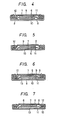
- FIG. 2 Another type of known capacitor now in use is shown in Fig. 2 in which a non-polarizable electrode 5 is used as one electrode.
- solvents used for the electrolytic solution are propylene carbonate, r-butyrolactone, N,N-dimethylformaldehyde, and acetonitrile.
- the stainless steel in the electrolytic solution cannot make a complete passive state but dissolves in the solution.
- the potential at which the current starts to run owing to the dissolution is 2.3-2.4 volts which is determined depending on the decomposition potential of the solvent at the cathode. This is lower than the potential of oxidation of active carbon or the potential of decomposition of the electrolyte in the electrolytic solution using the organic solvents.
- the potential at the anode is restricted by the poential of dissolution of the stainless steel, so that a potential of 3 V which is in an electrochemically stable potential region determined by the polarizable electrode 1 and the electrolytic solution could not be effectively utilized.
- One such a material may be titanium which forms a passive state in electrolytic solutions. As shown in Fig. 3, however, the breakdown voltage becomes higher than in the case using stainless steel. With electrolytic solutions using propylene carbonate and tetraethylammonium perchlorate, the region where the reactive current flows increases by about 0.8 V. However, the internal resistance increases, so that when the voltage drop becomes large in case where the electric double layer capacitor is used, with an attendant problem that such a capacitor cannot be in use.
- the present invention is contemplated to solve the above problem and has for its object the provision of an electric double layer capacitor which has a high breakdown voltage over 3 V.
- the present invention contemplates to solve the above problem and has for its object the provision of an electric double layer capacitor having a high breakdown voltage over 3 V.
- the present invention has such an arrangement that a metallic case piece at the side of an anode which is in contact with a conductive electrode and electrolyte is provided with an aluminium layer on the inner surface thereof.
- a metallic case piece at the side of an anode which is in contact with a conductive electrode and electrolyte is provided with an aluminium layer on the inner surface thereof.
- an oxide film is formed on the aluminium layer according to an applied voltage.
- no reactive current passes, so that the reaction of dissolution can be inhibited.
- an electric double layer capacitor which is electrochemically stable even when a potential of 3 V is applied.
- the collector metal serves also as a material for the case and should have high strength sufficient for the case. If the case is constituted of aluminium alone, the strength is not satisfactory. In addition, because a limitation is placed on the thickness of the case from the standpoint of a product size, too large a thickness is not practical. Under these restricting conditions, it is necessary to use a material, such as stainless steel, which has little problem in electric connection on use as an external terminal and high strength, in combination with aluminium.
- Figs. 1 and 2 are, respectively, sectional views of known electric double layer capacitors;
- Fig. 3 is a potential-current characteristic of electric double layer capcitors using stainless steel and titanium;
- Fig. 4 is a sectional view of an electric double layer capacitor according to one embodiment of the invention; and
- Figs. 5-7 are, respectively, sectional views of further embodiments of the invention.
- An embodiment shown in Fig. 4 includes polarizable electrodes 6 each made of an active carbon fiber cloth or a molding of a mixture of an active carbon powder and a binder.
- An aluminium conductive electrode 7 is formed on one side of the electrodes 6 by plasma spray coating.
- the polarizable electrodes 6 are encased in metallic case pieces 9, 10 of stainless steel which have an aluminium layer 8 on the inner surfaces thereof in such a way that the conductive electrodes 7 contact the inner surfaces of the case pieces 9, 10.
- the conductive electrodes 7 are connected to the metallic case pieces 9, 10 by spot welding.
- One of the polarizable electrodes 6 which is a counter electrode at the side of the cathode is impregnated with an electrolytic solution which has 10 wt% of tetraethylammonium tetrafluoroborate added to propylene carbonate.
- An ion-permeable separator 11 is provided between the polarizable electrodes 6 and a gasket 12 is arranged around the open periphery of the metallic case pieces 9, 10 and the metallic piece 10 is subjected to curling to complete a sealed case.
- a capacitor shown in Fig. 5 is an embodiment where no aluminium layer is formed on the inner surface of the metallic case piece 10 at the side of the cathode.
- a capacitor which is similar to Fig. 4 but a non-polarizable counter electrode 13 of, for example, lithium is used as a cathode and the metallic case pieces 9, 10 have, respectively, aluminium layers 8 on the inner surfaces thereof.
- Fig. 7 shows another embodiment in which a non-polarizable electrode is used as the counter electrode 13 and the metallic case piece 10 has an inner aluminium layer at the side of the counter electrode 13.
- the metallic case pieces 9, 10 may be made of, aside from stainless steel, iron, nickel, titanium and copper alloys.
- a 250 micrometer thick aluminium conductive electrode 7 is formed by plasma spray coating on one surface of a polarizable electrode 6 consisting of a phenolic active carbon fiber cloth (thickness 0.5 mm, specific surface area 2000 m 2 /g).
- a polarizable electrode 6 consisting of a phenolic active carbon fiber cloth (thickness 0.5 mm, specific surface area 2000 m 2 /g).
- This double-layered construction is punched in the form of a disk having a diameter of 2 cm to obtain electrodes.
- the electrodes are impregnated with an electrolytic solution having 10 wt% of tetraethylammonium tetrafluoroborate in propylene carbonate, after which they are superposed through separator 11.
- This unit is encased in a stainless steel case made of pieces 9,10 which is covered with an aluminium layer 8 (such as a layer having a purity of 99.86% and a thickness of 70 micrometers or a layer having a purity of 99.99% and a thickness of 60 micrometers) only on the inner surface contacting the anode or on inner surfaces contacting both electrodes.
- a gasket 12 is provided in an open end between the metallic case pieces 9, 10 and caulked to close the opening.
- Coconut shell active carbon particles are mixed with a polyflon binder and molded (thickness 0.5 mm, specific surface area 800 m 2 fg) to obtain a polarizable electrode 6.
- the electrode is formed with a 250 micrometer thick aluminium conductive electrode 7 by plasma spray coating. This double-layered construction is punched into disks having a diameter of 2 cm to obtain electrodes.
- the electrodes are impregnated with an electrolytic solution of 10 wt% of tetraethylammonium tetrafluoroborate in propylene carbonate and superposed through a separator 11 and sandwiched between metallic case pieces 9, 10 in which the stainless steel case piece 9 alone or pieces 9, 10 are covered with an aluminium layer 8 (purity 99.86%, thickness 70 micrometers) on the inner surface or surfaces thereof.
- the metallic case pieces 9, 10 are closed with a gasket 12 at the opening therebetween.
- a polarizable electrode 6 of an acrylic active carbon fiber cloth (thickness 0.5 mm, specific surface ares 800 m 2 fg) is formed with a 250 micrometer thick aluminium conductive electrode 7 by plasma spray coating.
- This double-layered construction is punched into a disk having a diameter of 2 cm, thereby obtaining an anode electrode.
- This electrode is superposed with a lithium non-polarizable electrode 13 having a diameter of 2 cm through a separator 11 to obtain an electode pair.
- This pair is impregnated with an electrolytic solution of 10 wt% of lithium tetrafluoroborate in propylene carbonate and sandwiched with stainless steel case pieces 9, 10 in which the stainless steel piece 9 alone or the pieces 9, 10 are covered with an aluminium layer (purity 99.99%, thickness 60 micrometers) on the inner surfaces thereof.
- the open end between the case pieces 9,10 is provided with a gasket 12 and caulked to close the pieces.
- an electric double layer capacitor of a high breakdown voltage of 3 V or higher can be readily fabricated in which an aluminium layer is formed at least on the inner surface of a metallic case at the side of the anode.
- the aluminium layer is formed with an electrochemically stable anodized film according to an applied voltage and the resistance of the film is so low as not to present practical problems. This property of the aluminium film is effectively utilized for the fabrication.
Abstract
Description
- This invention relates to an electric double layer capacitor utilizing an electric double layer formed at the interface between polarizable electrodes and an electrolyte as known from EP-A-0 112 9237.
- Known electric double layer capacitors of the type mentioned above are comprised of, as shown in Fig. 1,
polarizable electrodes 1 which are obtained by press molding of active carbon particles, by applying a mixture of active carbon particles and an appropriate binder onto a collector metal, or by forming a spray coating layer of aluminium on active carbon fibres. Thepolarizable electrodes 1 are accommodated in astainless steel case 2 and are facing each other through an electrolytic solution and aseparator 3. Themetallic case 2 is sealed through agasket 4 at a peripheral opening thereof. - Another type of known capacitor now in use is shown in Fig. 2 in which a
non-polarizable electrode 5 is used as one electrode. - In these known arrangements, solvents used for the electrolytic solution are propylene carbonate, r-butyrolactone, N,N-dimethylformaldehyde, and acetonitrile. In the case of polarization at the anode, the stainless steel in the electrolytic solution cannot make a complete passive state but dissolves in the solution. The potential at which the current starts to run owing to the dissolution is 2.3-2.4 volts which is determined depending on the decomposition potential of the solvent at the cathode. This is lower than the potential of oxidation of active carbon or the potential of decomposition of the electrolyte in the electrolytic solution using the organic solvents. Accordingly, when the
stainless steel case 2 is used as a current collector, the potential at the anode is restricted by the poential of dissolution of the stainless steel, so that a potential of 3 V which is in an electrochemically stable potential region determined by thepolarizable electrode 1 and the electrolytic solution could not be effectively utilized. - For instance, when an excess voltage over a voltage at which a leakage current starts to increase is applied, large amounts of iron, nickel and the like are detected in the electrolytic solution at the side of the anode, from which it has been confirmed that the stainless steel is dissolved and iron ions are moved from the anode toward the cathode.
- As will be seen from the above, when stainless steel is used as the
metallic case 2, it is difficult to effectively utilize a potential of 3 V which is in an electrochemically stable region determined by the active carbonpolarizable electrode 1 and the electrolytic solution. In order to obtain an electric double layer capacitor of a breakdown voltage which enables one to use 3 V, it is necessary to use a material which allows passage of a reactive current at a potential equal to or larger than active carbon of thepolarizable electrode 1 and which has strength sufficient as the case if the anode is subjected to polarization in a solvent used. - One such a material may be titanium which forms a passive state in electrolytic solutions. As shown in Fig. 3, however, the breakdown voltage becomes higher than in the case using stainless steel. With electrolytic solutions using propylene carbonate and tetraethylammonium perchlorate, the region where the reactive current flows increases by about 0.8 V. However, the internal resistance increases, so that when the voltage drop becomes large in case where the electric double layer capacitor is used, with an attendant problem that such a capacitor cannot be in use. The present invention is contemplated to solve the above problem and has for its object the provision of an electric double layer capacitor which has a high breakdown voltage over 3 V.
- The present invention contemplates to solve the above problem and has for its object the provision of an electric double layer capacitor having a high breakdown voltage over 3 V.
- More particularly, the present invention has such an arrangement that a metallic case piece at the side of an anode which is in contact with a conductive electrode and electrolyte is provided with an aluminium layer on the inner surface thereof. When aluminium is formed on the surface in contact with the electrolyte, an oxide film is formed on the aluminium layer according to an applied voltage. In a region to which a voltage has once been applied, no reactive current passes, so that the reaction of dissolution can be inhibited. Thus, there can be obtained an electric double layer capacitor which is electrochemically stable even when a potential of 3 V is applied.
- Because the aluminium oxide film thickness is small and thus the resistance is low, an increase of the internal resistance as in the case using titanium does not occur at a low voltage of about 3 volts. In this case, the collector metal serves also as a material for the case and should have high strength sufficient for the case. If the case is constituted of aluminium alone, the strength is not satisfactory. In addition, because a limitation is placed on the thickness of the case from the standpoint of a product size, too large a thickness is not practical. Under these restricting conditions, it is necessary to use a material, such as stainless steel, which has little problem in electric connection on use as an external terminal and high strength, in combination with aluminium.
- Figs. 1 and 2 are, respectively, sectional views of known electric double layer capacitors; Fig. 3 is a potential-current characteristic of electric double layer capcitors using stainless steel and titanium; Fig. 4 is a sectional view of an electric double layer capacitor according to one embodiment of the invention; and Figs. 5-7 are, respectively, sectional views of further embodiments of the invention.
- Embodiments of the invention are described with reference to Figs. 4 through 7.
- An embodiment shown in Fig. 4 includes
polarizable electrodes 6 each made of an active carbon fiber cloth or a molding of a mixture of an active carbon powder and a binder. An aluminiumconductive electrode 7 is formed on one side of theelectrodes 6 by plasma spray coating. Thepolarizable electrodes 6 are encased inmetallic case pieces aluminium layer 8 on the inner surfaces thereof in such a way that theconductive electrodes 7 contact the inner surfaces of thecase pieces conductive electrodes 7 are connected to themetallic case pieces polarizable electrodes 6 which is a counter electrode at the side of the cathode is impregnated with an electrolytic solution which has 10 wt% of tetraethylammonium tetrafluoroborate added to propylene carbonate. An ion-permeable separator 11 is provided between thepolarizable electrodes 6 and agasket 12 is arranged around the open periphery of themetallic case pieces metallic piece 10 is subjected to curling to complete a sealed case. - A capacitor shown in Fig. 5 is an embodiment where no aluminium layer is formed on the inner surface of the
metallic case piece 10 at the side of the cathode. - In Fig. 6, there is shown a capacitor which is similar to Fig. 4 but a
non-polarizable counter electrode 13 of, for example, lithium is used as a cathode and themetallic case pieces aluminium layers 8 on the inner surfaces thereof. - Fig. 7 shows another embodiment in which a non-polarizable electrode is used as the
counter electrode 13 and themetallic case piece 10 has an inner aluminium layer at the side of thecounter electrode 13. - The
metallic case pieces - The present invention is described by way of examples.
- In the embodiments shown in Figs. 4 and 5, a 250 micrometer thick aluminium
conductive electrode 7 is formed by plasma spray coating on one surface of apolarizable electrode 6 consisting of a phenolic active carbon fiber cloth (thickness 0.5 mm, specific surface area 2000 m2/g). This double-layered construction is punched in the form of a disk having a diameter of 2 cm to obtain electrodes. The electrodes are impregnated with an electrolytic solution having 10 wt% of tetraethylammonium tetrafluoroborate in propylene carbonate, after which they are superposed throughseparator 11. This unit is encased in a stainless steel case made ofpieces gasket 12 is provided in an open end between themetallic case pieces - Several characteristics of the electric double layer capacitors according to the invention are indicated in Table 1 as Nos. 1-3. In Table 1, characteristics of an electric double layer capacitor for comparison in which the stainless steel case is not covered with aluminium on the inner surfaces thereof are indicated as No. 6.
- Coconut shell active carbon particles are mixed with a polyflon binder and molded (thickness 0.5 mm, specific surface area 800 m2fg) to obtain a
polarizable electrode 6. The electrode is formed with a 250 micrometer thick aluminiumconductive electrode 7 by plasma spray coating. This double-layered construction is punched into disks having a diameter of 2 cm to obtain electrodes. The electrodes are impregnated with an electrolytic solution of 10 wt% of tetraethylammonium tetrafluoroborate in propylene carbonate and superposed through aseparator 11 and sandwiched betweenmetallic case pieces steel case piece 9 alone orpieces metallic case pieces gasket 12 at the opening therebetween. - In Table 1, the characteristics of the electric double layer capacitors of the invention are shown as Nos. 4 and 5.

- As shown in Figs. 6 and 7, a
polarizable electrode 6 of an acrylic active carbon fiber cloth (thickness 0.5 mm, specific surface ares 800 m2fg) is formed with a 250 micrometer thick aluminiumconductive electrode 7 by plasma spray coating. This double-layered construction is punched into a disk having a diameter of 2 cm, thereby obtaining an anode electrode. This electrode is superposed with a lithiumnon-polarizable electrode 13 having a diameter of 2 cm through aseparator 11 to obtain an electode pair. This pair is impregnated with an electrolytic solution of 10 wt% of lithium tetrafluoroborate in propylene carbonate and sandwiched with stainlesssteel case pieces stainless steel piece 9 alone or thepieces case pieces gasket 12 and caulked to close the pieces. - In Table 2, there are shown characteristics of the electric double layer capacitors of the invention as Nos. 1 and 2. For comparison, there are also shown characteristics of an electric double layer capacitor in which no aluminium layer is formed on the inner surfaces of a metallic case as No. 3.

- As will be understood from the foregoing, according to the present invention, an electric double layer capacitor of a high breakdown voltage of 3 V or higher can be readily fabricated in which an aluminium layer is formed at least on the inner surface of a metallic case at the side of the anode. The aluminium layer is formed with an electrochemically stable anodized film according to an applied voltage and the resistance of the film is so low as not to present practical problems. This property of the aluminium film is effectively utilized for the fabrication.
Claims (5)
Applications Claiming Priority (2)
| Application Number | Priority Date | Filing Date | Title |
|---|---|---|---|
| JP59277221A JPH0658864B2 (en) | 1984-12-25 | 1984-12-25 | Electric double layer capacitor |
| JP277221/84 | 1984-12-25 |
Publications (3)
| Publication Number | Publication Date |
|---|---|
| EP0207167A1 EP0207167A1 (en) | 1987-01-07 |
| EP0207167A4 EP0207167A4 (en) | 1987-07-13 |
| EP0207167B1 true EP0207167B1 (en) | 1988-10-26 |
Family
ID=17580500
Family Applications (1)
| Application Number | Title | Priority Date | Filing Date |
|---|---|---|---|
| EP86900265A Expired EP0207167B1 (en) | 1984-12-25 | 1985-12-24 | Electric double layer capacitor |
Country Status (6)
| Country | Link |
|---|---|
| US (1) | US4709303A (en) |
| EP (1) | EP0207167B1 (en) |
| JP (1) | JPH0658864B2 (en) |
| KR (1) | KR900003211B1 (en) |
| DE (1) | DE3565906D1 (en) |
| WO (1) | WO1986003884A1 (en) |
Cited By (6)
| Publication number | Priority date | Publication date | Assignee | Title |
|---|---|---|---|---|
| US6643119B2 (en) | 2001-11-02 | 2003-11-04 | Maxwell Technologies, Inc. | Electrochemical double layer capacitor having carbon powder electrodes |
| US7722686B2 (en) | 2004-02-19 | 2010-05-25 | Maxwell Technologies, Inc. | Composite electrode and method for fabricating same |
| US7791861B2 (en) | 2003-07-09 | 2010-09-07 | Maxwell Technologies, Inc. | Dry particle based energy storage device product |
| US7791860B2 (en) | 2003-07-09 | 2010-09-07 | Maxwell Technologies, Inc. | Particle based electrodes and methods of making same |
| US7859826B2 (en) | 2005-03-14 | 2010-12-28 | Maxwell Technologies, Inc. | Thermal interconnects for coupling energy storage devices |
| US7920371B2 (en) | 2003-09-12 | 2011-04-05 | Maxwell Technologies, Inc. | Electrical energy storage devices with separator between electrodes and methods for fabricating the devices |
Families Citing this family (35)
| Publication number | Priority date | Publication date | Assignee | Title |
|---|---|---|---|---|
| JPS6356372A (en) * | 1986-08-25 | 1988-03-10 | Hitachi Cable Ltd | Aluminum/stainless steel clad material and its production |
| JPH01310524A (en) * | 1988-06-09 | 1989-12-14 | Matsushita Electric Ind Co Ltd | Electric double-layer capacitor |
| JPH01310525A (en) * | 1988-06-09 | 1989-12-14 | Matsushita Electric Ind Co Ltd | Electric double-layer capacitor |
| EP0449145B1 (en) * | 1990-03-29 | 1998-01-28 | Matsushita Electric Industrial Co., Ltd. | Electric double layer capacitor and method for producing the same |
| JP3125341B2 (en) * | 1991-08-20 | 2001-01-15 | 株式会社村田製作所 | Multilayer electric double layer capacitors |
| US5260855A (en) * | 1992-01-17 | 1993-11-09 | Kaschmitter James L | Supercapacitors based on carbon foams |
| US5418682A (en) * | 1994-06-16 | 1995-05-23 | Rockwell International Corporation | Capacitor having an electrolyte containing a mixture of dinitriles |
| US5862035A (en) | 1994-10-07 | 1999-01-19 | Maxwell Energy Products, Inc. | Multi-electrode double layer capacitor having single electrolyte seal and aluminum-impregnated carbon cloth electrodes |
| US5621607A (en) * | 1994-10-07 | 1997-04-15 | Maxwell Laboratories, Inc. | High performance double layer capacitors including aluminum carbon composite electrodes |
| US6233135B1 (en) | 1994-10-07 | 2001-05-15 | Maxwell Energy Products, Inc. | Multi-electrode double layer capacitor having single electrolyte seal and aluminum-impregnated carbon cloth electrodes |
| US6195251B1 (en) * | 1997-10-29 | 2001-02-27 | Asahi Glass Company Ltd. | Electrode assembly and electric double layer capacitor having the electrode assembly |
| JPH11168033A (en) * | 1997-12-03 | 1999-06-22 | Asahi Glass Co Ltd | Electric double-layer capacitor |
| JP3241325B2 (en) * | 1998-07-31 | 2001-12-25 | 日本電気株式会社 | Electric double layer capacitor |
| US7042708B1 (en) * | 1998-10-13 | 2006-05-09 | Selected Molecular Technologies Corporation | High capacitance energy storage device |
| US6222723B1 (en) | 1998-12-07 | 2001-04-24 | Joint Stock Company “Elton” | Asymmetric electrochemical capacitor and method of making |
| US6181546B1 (en) * | 1999-01-19 | 2001-01-30 | Aktsionernoe Obschestvo Zakrytogo Tipa “Elton” | Double layer capacitor |
| US6449139B1 (en) | 1999-08-18 | 2002-09-10 | Maxwell Electronic Components Group, Inc. | Multi-electrode double layer capacitor having hermetic electrolyte seal |
| EP1139356A4 (en) * | 1999-09-13 | 2005-11-30 | Asahi Glass Co Ltd | Electric double-layer capacitor |
| US6352565B2 (en) | 1999-12-14 | 2002-03-05 | Asahi Glass Company Ltd. | Electric double layer capacitor |
| US6631074B2 (en) | 2000-05-12 | 2003-10-07 | Maxwell Technologies, Inc. | Electrochemical double layer capacitor having carbon powder electrodes |
| DE10060653A1 (en) * | 2000-12-06 | 2002-06-20 | Epcos Ag | Electric double layer capacitor |
| US6813139B2 (en) | 2001-11-02 | 2004-11-02 | Maxwell Technologies, Inc. | Electrochemical double layer capacitor having carbon powder electrodes |
| US20070122698A1 (en) * | 2004-04-02 | 2007-05-31 | Maxwell Technologies, Inc. | Dry-particle based adhesive and dry film and methods of making same |
| US20060147712A1 (en) * | 2003-07-09 | 2006-07-06 | Maxwell Technologies, Inc. | Dry particle based adhesive electrode and methods of making same |
| US20110165318A9 (en) * | 2004-04-02 | 2011-07-07 | Maxwell Technologies, Inc. | Electrode formation by lamination of particles onto a current collector |
| US7325285B2 (en) * | 2004-05-28 | 2008-02-05 | Maxwell Technologies, Inc. | Method of processing high voltage capacitors |
| JP4694826B2 (en) * | 2004-12-08 | 2011-06-08 | セイコーインスツル株式会社 | Electrochemical cell and method for producing the same |
| US7692411B2 (en) * | 2006-01-05 | 2010-04-06 | Tpl, Inc. | System for energy harvesting and/or generation, storage, and delivery |
| US7864507B2 (en) | 2006-09-06 | 2011-01-04 | Tpl, Inc. | Capacitors with low equivalent series resistance |
| US20080241656A1 (en) * | 2007-03-31 | 2008-10-02 | John Miller | Corrugated electrode core terminal interface apparatus and article of manufacture |
| US20080235944A1 (en) * | 2007-03-31 | 2008-10-02 | John Miller | Method of making a corrugated electrode core terminal interface |
| JP5032636B2 (en) * | 2010-07-08 | 2012-09-26 | セイコーインスツル株式会社 | Electrochemical cell and method for producing the same |
| US8508916B2 (en) * | 2010-10-13 | 2013-08-13 | Cooper Technologies Company | High voltage electric double layer capacitor device and methods of manufacture |
| KR102037266B1 (en) * | 2012-12-14 | 2019-10-29 | 삼성전기주식회사 | Electrode structure and apparatus for storaging energy with the same |
| JP6654031B2 (en) * | 2015-12-14 | 2020-02-26 | セイコーインスツル株式会社 | Small electronic equipment |
Citations (2)
| Publication number | Priority date | Publication date | Assignee | Title |
|---|---|---|---|---|
| JPS4713577A (en) * | 1970-12-28 | 1972-07-13 | ||
| JPS5656646U (en) * | 1979-10-05 | 1981-05-16 |
Family Cites Families (8)
| Publication number | Priority date | Publication date | Assignee | Title |
|---|---|---|---|---|
| US2733389A (en) * | 1956-01-31 | ellison | ||
| US3700975A (en) * | 1971-11-12 | 1972-10-24 | Bell Telephone Labor Inc | Double layer capacitor with liquid electrolyte |
| US4313084A (en) * | 1978-03-27 | 1982-01-26 | Nippon Electric Co., Ltd. | Laminated structure of double-layer capacitor |
| FR2471659A1 (en) * | 1979-12-27 | 1981-06-19 | Nippon Electric Co | SELF-SUPPORTING DOUBLE LAYER ELECTRIC CAPACITOR |
| JPS594114A (en) * | 1982-06-30 | 1984-01-10 | 松下電器産業株式会社 | Electric double layer capacitor |
| JPS59151414A (en) * | 1983-02-17 | 1984-08-29 | 松下電器産業株式会社 | Electric double layer capacitor |
| US4542444A (en) * | 1983-12-27 | 1985-09-17 | The Standard Oil Company | Double layer energy storage device |
| US4563723A (en) * | 1984-07-30 | 1986-01-07 | Gordon G. Waltenspiel | Chargeable electrical power source |
-
1984
- 1984-12-25 JP JP59277221A patent/JPH0658864B2/en not_active Expired - Lifetime
-
1985
- 1985-12-24 WO PCT/JP1985/000706 patent/WO1986003884A1/en active IP Right Grant
- 1985-12-24 KR KR1019860700600A patent/KR900003211B1/en not_active IP Right Cessation
- 1985-12-24 DE DE8686900265T patent/DE3565906D1/en not_active Expired
- 1985-12-24 EP EP86900265A patent/EP0207167B1/en not_active Expired
- 1985-12-24 US US06/903,566 patent/US4709303A/en not_active Expired - Lifetime
Patent Citations (2)
| Publication number | Priority date | Publication date | Assignee | Title |
|---|---|---|---|---|
| JPS4713577A (en) * | 1970-12-28 | 1972-07-13 | ||
| JPS5656646U (en) * | 1979-10-05 | 1981-05-16 |
Cited By (7)
| Publication number | Priority date | Publication date | Assignee | Title |
|---|---|---|---|---|
| US6643119B2 (en) | 2001-11-02 | 2003-11-04 | Maxwell Technologies, Inc. | Electrochemical double layer capacitor having carbon powder electrodes |
| US7791861B2 (en) | 2003-07-09 | 2010-09-07 | Maxwell Technologies, Inc. | Dry particle based energy storage device product |
| US7791860B2 (en) | 2003-07-09 | 2010-09-07 | Maxwell Technologies, Inc. | Particle based electrodes and methods of making same |
| US8072734B2 (en) | 2003-07-09 | 2011-12-06 | Maxwell Technologies, Inc. | Dry particle based energy storage device product |
| US7920371B2 (en) | 2003-09-12 | 2011-04-05 | Maxwell Technologies, Inc. | Electrical energy storage devices with separator between electrodes and methods for fabricating the devices |
| US7722686B2 (en) | 2004-02-19 | 2010-05-25 | Maxwell Technologies, Inc. | Composite electrode and method for fabricating same |
| US7859826B2 (en) | 2005-03-14 | 2010-12-28 | Maxwell Technologies, Inc. | Thermal interconnects for coupling energy storage devices |
Also Published As
| Publication number | Publication date |
|---|---|
| KR880700440A (en) | 1988-03-15 |
| KR900003211B1 (en) | 1990-05-10 |
| WO1986003884A1 (en) | 1986-07-03 |
| US4709303A (en) | 1987-11-24 |
| EP0207167A1 (en) | 1987-01-07 |
| EP0207167A4 (en) | 1987-07-13 |
| JPH0658864B2 (en) | 1994-08-03 |
| JPS61150317A (en) | 1986-07-09 |
| DE3565906D1 (en) | 1988-12-01 |
Similar Documents
| Publication | Publication Date | Title |
|---|---|---|
| EP0207167B1 (en) | Electric double layer capacitor | |
| US4757424A (en) | Electric double layer capacitor | |
| JPS61203614A (en) | Electric doule-layer capacitor | |
| JPS61203616A (en) | Electric doule-layer capacitor | |
| JPS60182123A (en) | Electric couble layer capacitor | |
| JPS61203617A (en) | Electric doule-layer capacitor | |
| JPH04233210A (en) | Electric double layer capacitor | |
| JPH0345893B2 (en) | ||
| JPS63261815A (en) | Electric double-layer capacitor | |
| JPS61203624A (en) | Electric double-layer capacitor | |
| JP3132181B2 (en) | Electric double layer capacitor | |
| JP3309436B2 (en) | Electric double layer capacitor | |
| JPH0426106A (en) | Electric double layer capacitor | |
| JPS63296328A (en) | Dipole domain capacitor | |
| CN1006503B (en) | Dual-layer capacitor | |
| JPS60167410A (en) | Electric double layer capacitor | |
| JPS593914A (en) | Electric double layer capacitor | |
| JPS59151414A (en) | Electric double layer capacitor | |
| JPS61203625A (en) | Electric double-layer capacitor | |
| JPH0226009A (en) | Electric double-layer capacitor | |
| JPH0329285B2 (en) | ||
| JPS61203620A (en) | Electric double-layer capacitor | |
| JPH01222427A (en) | Electric double layer capacitor | |
| JPS63265414A (en) | Electric double layer capacitor | |
| JPS61203622A (en) | Electric double-layer capacitor |
Legal Events
| Date | Code | Title | Description |
|---|---|---|---|
| PUAI | Public reference made under article 153(3) epc to a published international application that has entered the european phase |
Free format text: ORIGINAL CODE: 0009012 |
|
| 17P | Request for examination filed |
Effective date: 19860822 |
|
| AK | Designated contracting states |
Kind code of ref document: A1 Designated state(s): CH DE FR GB LI |
|
| A4 | Supplementary search report drawn up and despatched |
Effective date: 19870713 |
|
| 17Q | First examination report despatched |
Effective date: 19871222 |
|
| GRAA | (expected) grant |
Free format text: ORIGINAL CODE: 0009210 |
|
| AK | Designated contracting states |
Kind code of ref document: B1 Designated state(s): CH DE FR GB LI |
|
| REF | Corresponds to: |
Ref document number: 3565906 Country of ref document: DE Date of ref document: 19881201 |
|
| ET | Fr: translation filed | ||
| PLBE | No opposition filed within time limit |
Free format text: ORIGINAL CODE: 0009261 |
|
| STAA | Information on the status of an ep patent application or granted ep patent |
Free format text: STATUS: NO OPPOSITION FILED WITHIN TIME LIMIT |
|
| 26N | No opposition filed | ||
| REG | Reference to a national code |
Ref country code: GB Ref legal event code: 746 Effective date: 19950928 |
|
| REG | Reference to a national code |
Ref country code: FR Ref legal event code: D6 |
|
| REG | Reference to a national code |
Ref country code: GB Ref legal event code: IF02 |
|
| PGFP | Annual fee paid to national office [announced via postgrant information from national office to epo] |
Ref country code: FR Payment date: 20041208 Year of fee payment: 20 |
|
| PGFP | Annual fee paid to national office [announced via postgrant information from national office to epo] |
Ref country code: DE Payment date: 20041216 Year of fee payment: 20 |
|
| PGFP | Annual fee paid to national office [announced via postgrant information from national office to epo] |
Ref country code: GB Payment date: 20041222 Year of fee payment: 20 |
|
| PGFP | Annual fee paid to national office [announced via postgrant information from national office to epo] |
Ref country code: CH Payment date: 20041229 Year of fee payment: 20 |
|
| PG25 | Lapsed in a contracting state [announced via postgrant information from national office to epo] |
Ref country code: GB Free format text: LAPSE BECAUSE OF EXPIRATION OF PROTECTION Effective date: 20051223 |
|
| REG | Reference to a national code |
Ref country code: GB Ref legal event code: PE20 |
|
| REG | Reference to a national code |
Ref country code: CH Ref legal event code: PL |