EP0207203A2 - Electrostatic dust collector - Google Patents
Electrostatic dust collector Download PDFInfo
- Publication number
- EP0207203A2 EP0207203A2 EP85305054A EP85305054A EP0207203A2 EP 0207203 A2 EP0207203 A2 EP 0207203A2 EP 85305054 A EP85305054 A EP 85305054A EP 85305054 A EP85305054 A EP 85305054A EP 0207203 A2 EP0207203 A2 EP 0207203A2
- Authority
- EP
- European Patent Office
- Prior art keywords
- dust collector
- electrodes
- filter element
- electrostatic dust
- electrode
- Prior art date
- Legal status (The legal status is an assumption and is not a legal conclusion. Google has not performed a legal analysis and makes no representation as to the accuracy of the status listed.)
- Granted
Links
Images


Classifications
-
- B—PERFORMING OPERATIONS; TRANSPORTING
- B03—SEPARATION OF SOLID MATERIALS USING LIQUIDS OR USING PNEUMATIC TABLES OR JIGS; MAGNETIC OR ELECTROSTATIC SEPARATION OF SOLID MATERIALS FROM SOLID MATERIALS OR FLUIDS; SEPARATION BY HIGH-VOLTAGE ELECTRIC FIELDS
- B03C—MAGNETIC OR ELECTROSTATIC SEPARATION OF SOLID MATERIALS FROM SOLID MATERIALS OR FLUIDS; SEPARATION BY HIGH-VOLTAGE ELECTRIC FIELDS
- B03C3/00—Separating dispersed particles from gases or vapour, e.g. air, by electrostatic effect
- B03C3/02—Plant or installations having external electricity supply
- B03C3/04—Plant or installations having external electricity supply dry type
- B03C3/14—Plant or installations having external electricity supply dry type characterised by the additional use of mechanical effects, e.g. gravity
- B03C3/155—Filtration
Definitions
- the present invention relates to an electrostatic dust collector which uses a porous dielectric as a diaphragm between electrodes.
- an electrostatic dust collector for the purpose of eliminating air pollution by smoke or the like, an electrostatic dust collector has been used in which microparticles in gases to be eliminated are permitted to be charged in a corona discharge area, and gases are permitted pass through and between plates to which high voltage is applied to electrostatically adsorb the charged particles.
- This system has merits that microparticles having a diameter of approximately 0.1 ⁇ can be collected, and the pressure loss resulting from the dust collector is very small.
- this system is sufferred from disadvantages that a corona discharge section and a collecting section have to be provided resulting in complex construction; if the collecting performance is intended to be increased, high applied voltage has to be used or a voltage applied section has to be extended, in which case, however, concentration of electric fields on a raised portion of microparticles accumulated on the plates causes a discharge to again scatter the collected microparticles; and the device becomes large-scaled.
- the present inventor has previously developed an electrostatic dust collector which has not found in the past, wherein electrodes are disposed on opposite surfaces of a porous dielectric, an intense electric field is applied to the porous dielectric so that even particles having a particle size smaller than the bore of the porous dielectric may be collected, and a portion between electrodes is insulated by the dielectric to eliminate a danger of discharge resulting from accumulation of collected particles and the intense electric field can be applied.
- Japanese Patent Laid-Open No. 19564/84 Japanese Patent Laid-Open No. 19564/84.
- the present invention is an improvement over the aforesaid .dust collector to make application thereof to various uses possible.
- a porous dielectric is formed into pliable narrow strips, which are disorderly -packed into a net bag, whereby it is installed in an existing duct to be able to eliminate gases flowing through the duct irrespectively of a diameter and.shape in section thereof.
- the present invention also provides an arrangement wherein an electrode formed of an Al foil is adhered through a paraffin onto a porous dielectric such as urethane foam which is a filter medium, or At is vaporised on the surface on which cellulose acetate or the like is coated to form an electrode and coated thereon with a high molecular liquid such as polystyrene, or an electrode coated with a high-molecular monomer liquid such as polystyrene is attached to an electrode in which a foil is adhered to a high-molecular film or which is formed by vaporisation to thereby form an electrode free from direct contact with gas and thus without any danger of corrosion thus making elimination of corrosive gases containing formalin and SO possible.
- a porous dielectric such as urethane foam which is a filter medium, or At is vaporised on the surface on which cellulose acetate or the like is coated to form an electrode and coated thereon with a high molecular liquid such as polystyrene, or an electrode coated with
- the present invention also provides an arrangement wherein a plurality of electrodes are provided over the gas transmitting direction of a porous dielectric such as urethane foam constituting a filter element, and an electric field is repeatedly applied to the transmitting gases to thereby effectively collect microparticles which has been difficult to collect particles in the past.
- a porous dielectric such as urethane foam constituting a filter element
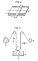
- Fig. 1 is a sectional view showing the conception of a dust collector in accordance with the present invention.
- a filter element 2 is disposed in the central portion of a casing 1.
- An intake flow A is drawn by a fan 3 and flows through an inlet 4.
- a filter bag 5 is disposed to collect coarse dusts.
- the filter element 2 is manufactured by cylindrically winding, as shown in Fig. 3, a plurality of filter media formed with a metal film 7 such as At on one surface of a porous dielectric material 6 such as urethane foam as shown in Fig. 2, and a high voltage is applied between adjacent electrodes by a DC high voltage power source 8.
- a reference numeral 10 designates a support net for the filter element 2.
- microparticles such as dusts floating in the air stream A drawn through the inlet 4 are physically collected in narrow holes of the filter media and also electrostatically collected while being charged by slipping relative to the filter media which are dielectric. Therefore; since a relatively samll thickness of the filter element will suffice, pressure loss can be minimized.
- Electrodes used to apply an electric field comprise the metal films 7 formed on the porous dielectric material 6, and the electrodes apart through the thickness of the dielectric material 6 are disposed merely by winding the metal film and therefore the spaced apart electrodes can be arranged very simply and held securely. Therefore, a uniform intense electric field can be formed within the filter element.
- a corona discharge section for charging dusts need not be provided, which has been necessary in conventional electrostatic dust collectors.
- the ratio between the length and diameter of the air stream passage is large and the charged particles are collected on passage walls by slight displacement of electrostatic attraction, and therefore the collecting efficiency is extremely good, and in addition, the portion between the electrodes is insulated by the dielectric material, and therefore no short-circuiting and discharge occur due to the accumulated dusts. Even if the short-circuiting and discharge should occur, microelectrode surfaces vaporise and the short-circuiting and discharge extinguish thus providing safety.
- the thickness of the foamed dielectric material is made small and the spacing between electrodes is made small whereby an applying voltage can be reduced to about one-thirds of that of conventional electrostatic dust collectors.
- this filter element is produced for example in the following procedure.
- an Aî foil 71 coated with paraffin is placed on one surface of a sheet 6 of dielectric foamed filter medium, heated by a heater 11 to a temperature at which the paraffin becomes molten, and lightly pressed to thereby bond them together.
- the width of the At foil is made slightly smaller than that of the filter medium sheet, leaving portions 61 to which electrode is not bonded on both sides.
- the filter medium 6 is cut along the center line thereof, and these are superposed each other and wound as shown in Fig. 2 to obtain the filter element 2.
- Fig. 5 illustrates one example of a device for coating paraffin on an At foil.
- the At foil drawn from an At foil supply roll 12 is preheated by a preheating fan 13 and thereafter comes into contact with a coating roll 16 which rotates within a paraffin bath 15 held at approximately 50°C by a heater 14.
- the foil is entirely coated with a predetermined quantity of paraffin, cooled and solidified by a cooling fan 17 and wound onto a winding roll 18.
- the winding roll is adhered to the dielectric foamed filter medium as shown in Fig. 4.
- the winding roll can be adhered to the filter medium immediately after paraffin has been coated and thereafter wound together with the filter medium.
- the cooling fan 17 and heater 9 can be omitted.
- Formation of electrodes on the dielectric foamed filter medium is not limited to the manner of the above-described embodiment but vacuum vaporisation can be employed.
- the surface is treated to be smooth to facilitate vaporisation, and cellulose acetate or cellulose ethyl is coated by spraying or by a roll to the thickness of dozens of microns on the surface of the filter medium. After the coated film has been dried, At or Zn film is coated on the surface thereof by vaccum vaprisation.
- This dust collector has an extremely simple construction as described above and has realized a dust collector which has the merits obtained by a dust collector consisting of an electrostatic dust collector and a filter. Moreover, the filter media can be easily produced in volume as described above, and if the lowering in efficiency due to the blinding or the like should occurs, the filter medium may be exchanged simply to always maintain a high dust collecting efficiency.
- the present device can be used even in fields which have been impossible to apply the electrostatic dust collector in the past.
- the device can be incorporated into an air heater for home use, a window fan and the like to collect pollen which causes asthma, dusts and the like to maintain the indoor clean, and besides, the device can be utilized as an air cleaner for home use which collects smoke of cigarettes.
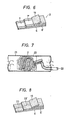
- Fig. 6 shows one embodiment of an improved filter element.
- Reference numerals 6, 6' and 19 designate porous dielectric materials formed of urethane foam or the like, which are in the form of a narrow strip having a suitable width. To one surface of the materials 6, 6' is adhered At foils 7, 7' narrower than the dielectric material by paraffin, adhesives and the like as described above, which form electrodes. Three dielectric materials 6, 6' and 19 are adhered so that the electrodes may not be exposed outside to form a filter element.
- This lengthy filter element 2 is disorderly forced into, for example, an insulating bag 20 such as a nylon net and forced into a duct 21, as shown in Fig. 7.
- a reference numeral 22 designates a high voltage power source. Since the filter element 2 is pliable and has a moderate elasticity, as described above, the filter element is wholly spread inside the duct 21 to cover the entire section irrespective of the size and shape in section of the duct 21.
- the filter element 2 when a high voltage is applied by the high voltage power source 22 to the electrodes 7, 7', the filter element 2 exhibits a great dust collecting performance with less pressure loss different from a mere filter.
- the filter elements 2 disorderly forced into the net bag 20 are porous themselves and can form a flowpassage for exhaust gases and in addition, form disorderly bended clearances between the intertwined elements 2 to impart only a relatively small resistance to an exhaust stream flowing through the clearances, and thus pressure loss of exhaust is small.
- the dusts contained in the exhaust come into contact with the porous dielectric material . forming walls of a narrow and bended passageway and are mechanically collected, charged by the adherence of ions created.due to the slipping or a high voltage between electrodes, and collected and retained by the porous dielectric material by the electric field formed between electrodes.
- the electric field formed between electrodes is produced not only in portions where the electrodes are opposed each other but bulges towards both sides thereof and also greatly bulges externally of the porous dielectric material. Therefore, as shown in Fig. 8, the electrodes can be copper wires 23, 23' instead of foils.
- this embodiment has the following characteristics:
- Fig. 9 shows an embodiment which is used for gases containing corrosive components. Electrodes 7, 7' are provided on porous dielectric materials 6, 6' in a manner similar to that as described in connection with Fig. 4. Paraffin coated on the electrodes 7, 7' forms a protective layer to prevent the Al foil of electrode from direct exposure to treated gases. However, if this is not sufficient, cellulose acetate or cellulose ethyl is applied by spraying or roll to surfaces 62, 62' of the narrow strips of the porous dielectric materials 6, 6' to further complete gas cut-off.
- polystyrene liquid is coated by spraying or roll on the narrow strips 6, 6' formed with electrodes to form films 24, 24' to provide a complete bag-like cover to thereby prevent the electrodes 7, 7' from direct contact with the treated gas.
- the aforesaid narrow strips 6, 6' are superposed to be wound into a disc-like configuration as shown in Fig. 3 or fully forced into the duct disorderly as shown in Fig. 7 and a high voltage is applied between the electrodes 3 and 4 whereby microparticles in gases passing through the element 2 can be collected in the porous dielectric.
- terminal portions of lead electrodes can be molded by heating them at a low temperature by use of paraffin after lead wires have been fixed to easily interrupt contact thereof with exhaust gases.
- a unique construction in which electrodes are provided on the dielectric can be utilized to easily form gas barrier covers on both surfaces of electrodes to completely prevent the lowering of a dust collecting performance due to the corrosion of electrodes.
- the filter element can be easily produced continuously from inexpensive materials such as urethane foam and can be of disposable type, and therefore, the filter element is suitable for eliminating gases containing corrosive components which are troublesome in treatment after collection.
- the device according to the present invention is suitable for use as a dust collector in facilities such as hospitals, animal breeding farms and the like which were not able to find suitable devices despite the fact that the necessity of such provisions has been recognized.
- Fig. 10 shows an embodiment in which a plurality of electrodes are provided on narrow strips of porous dielectric to thereby enhance the collecting performance of microparticles.
- At foils 72, 73; 72', 73' having a width of approximately 10 mm are attached at intervals of approximately 10 mm to one surface of a urethane foam having a thickness of approximately 10 mm and a width of approximately 50 mm, a filter is wound thereon, said filter having narrow strips 6, 6' superposed thereon formed with films 24, 24' by spraying polystyrene liquid to form a disc-like filter element 2 as shown in Fig. 3, and lead electrodes 9, 9' are connected to the electrodes 72, 73 and 72', 73' of the narrow strips 6, 6', respectively.
- the electrodes 72, 73 and 72', 73' can be of the same polarity or opposite polarity, and if the same polarity is employed, the construction of the lead electrodes becomes simple.
- Electrostatic adsorption requires the width of an electric field enough to receive an electrostatic force during the time the microparticles reach the collection surface and at the same time, needless to say, the intenser electric field, the higher the collection effect is obtained.
- the electrodes 3, 4, 5 and 6 comprise foils which have a predetermined width, and lines of electric force are-concentrated at the end edges of the electrodes by the edge effect as is well known, at which the high collection efficiency is exhibited. Since the end edges of the electrodes are present in both edges of the plurality of electrodes, portions where the collection performance is high appear through magnification of electrodes, and the collection performance as a whole seems-to be increased.
Abstract
Description
- The present invention relates to an electrostatic dust collector which uses a porous dielectric as a diaphragm between electrodes.
- To eliminate microparticles floating in exhaust gases or the like, it is the commonest to use a filter device which permits the particles to pass through a porous member to collect them. This system, however, involves problems that if the bore of a particle collecting material is less than a predetermined value, it is hard to collect the particles, and that if the thickness of a collecting material is made larger, the resistance of fluids which pass therethrough increases to increase a pressure loss. There was a limit in dust collecting performance.
- On the other hand, for the purpose of eliminating air pollution by smoke or the like, an electrostatic dust collector has been used in which microparticles in gases to be eliminated are permitted to be charged in a corona discharge area, and gases are permitted pass through and between plates to which high voltage is applied to electrostatically adsorb the charged particles. This system has merits that microparticles having a diameter of approximately 0.1µ can be collected, and the pressure loss resulting from the dust collector is very small. However, this system is sufferred from disadvantages that a corona discharge section and a collecting section have to be provided resulting in complex construction; if the collecting performance is intended to be increased, high applied voltage has to be used or a voltage applied section has to be extended, in which case, however, concentration of electric fields on a raised portion of microparticles accumulated on the plates causes a discharge to again scatter the collected microparticles; and the device becomes large-scaled.
- There poses a further problem that if any of these devices are installed in an existing duct or the like, they have to be specially designed to meet the size and shape of the duct.
- Moreover, in such devices as described above, since the collecting plates are exposed, the durable period is extremely short if they are used in corrosive environments, thus failing to actually use them. Because of this, the devices have been difficult to be used not only in installations involving exhaust gases in boilers containing SOx but in hospitals, animal breeding farms and the like containing formalin.
- The present inventor has previously developed an electrostatic dust collector which has not found in the past, wherein electrodes are disposed on opposite surfaces of a porous dielectric, an intense electric field is applied to the porous dielectric so that even particles having a particle size smaller than the bore of the porous dielectric may be collected, and a portion between electrodes is insulated by the dielectric to eliminate a danger of discharge resulting from accumulation of collected particles and the intense electric field can be applied. (Japanese Patent Laid-Open No. 19564/84). The present invention is an improvement over the aforesaid .dust collector to make application thereof to various uses possible.
- According to the present invention there is . providedan arrangement wherein a porous dielectric is formed into pliable narrow strips, which are disorderly -packed into a net bag, whereby it is installed in an existing duct to be able to eliminate gases flowing through the duct irrespectively of a diameter and.shape in section thereof.
- The present invention also provides an arrangement wherein an electrode formed of an Aℓ foil is adhered through a paraffin onto a porous dielectric such as urethane foam which is a filter medium, or At is vaporised on the surface on which cellulose acetate or the like is coated to form an electrode and coated thereon with a high molecular liquid such as polystyrene, or an electrode coated with a high-molecular monomer liquid such as polystyrene is attached to an electrode in which a foil is adhered to a high-molecular film or which is formed by vaporisation to thereby form an electrode free from direct contact with gas and thus without any danger of corrosion thus making elimination of corrosive gases containing formalin and SO possible.
- The present invention also
provides an arrangement wherein a plurality of electrodes are provided over the gas transmitting direction of a porous dielectric such as urethane foam constituting a filter element, and an electric field is repeatedly applied to the transmitting gases to thereby effectively collect microparticles which has been difficult to collect particles in the past. - Fig. 1 is a sectional view of one embodiment of a dust collector according to the present invention;
- Figs. 2 and 3 are perspective views, respectively, showing a construction of a filter element;
- Fig. 4 illustrates a method for adhering a metal foil to a filter medium;
- Fig. 5 is a schematic view of a device for coating a paraffin to a metal foil;
- Fig. 6 is an overall view of a first embodiment of a dust collector for disorderly packing into a duct;
- Fig. 7 is a fragmentary perspective view of one example of a filter element;
- Fig. 8 is a fragmentary perspective view of another example of the filter element;
- Fig. 9 is a fragmentary perspective view of one example of a filter element used under the corrosive atmosphere;
- Fig. 10 is a fragmentary perspective view of one example of a filter element having a plurality of electrodes; and
- Fig. 11 illustrates the dust collecting state.
- The present inventin will now be described in detail with reference to the accompanying drawings.
- Fig. 1 is a sectional view showing the conception of a dust collector in accordance with the present invention. A
filter element 2 is disposed in the central portion of a casing 1. An intake flow A is drawn by afan 3 and flows through an inlet 4. For reducing blinding of the filter element, afilter bag 5 is disposed to collect coarse dusts. - The
filter element 2 is manufactured by cylindrically winding, as shown in Fig. 3, a plurality of filter media formed with ametal film 7 such as At on one surface of a porousdielectric material 6 such as urethane foam as shown in Fig. 2, and a high voltage is applied between adjacent electrodes by a DC highvoltage power source 8. Areference numeral 10 designates a support net for thefilter element 2. - In the arrangement as described above, microparticles such as dusts floating in the air stream A drawn through the inlet 4 are physically collected in narrow holes of the filter media and also electrostatically collected while being charged by slipping relative to the filter media which are dielectric. Therefore; since a relatively samll thickness of the filter element will suffice, pressure loss can be minimized.
- Electrodes used to apply an electric field comprise the
metal films 7 formed on the porousdielectric material 6, and the electrodes apart through the thickness of thedielectric material 6 are disposed merely by winding the metal film and therefore the spaced apart electrodes can be arranged very simply and held securely. Therefore, a uniform intense electric field can be formed within the filter element. - A corona discharge section for charging dusts need not be provided, which has been necessary in conventional electrostatic dust collectors. The ratio between the length and diameter of the air stream passage is large and the charged particles are collected on passage walls by slight displacement of electrostatic attraction, and therefore the collecting efficiency is extremely good, and in addition, the portion between the electrodes is insulated by the dielectric material, and therefore no short-circuiting and discharge occur due to the accumulated dusts. Even if the short-circuiting and discharge should occur, microelectrode surfaces vaporise and the short-circuiting and discharge extinguish thus providing safety.
- Therefore, the thickness of the foamed dielectric material is made small and the spacing between electrodes is made small whereby an applying voltage can be reduced to about one-thirds of that of conventional electrostatic dust collectors.
- Preferably, this filter element is produced for example in the following procedure.
- In the embodiment shown in Fig. 4, an
Aî foil 71 coated with paraffin is placed on one surface of asheet 6 of dielectric foamed filter medium, heated by aheater 11 to a temperature at which the paraffin becomes molten, and lightly pressed to thereby bond them together. At that time, the width of the At foil is made slightly smaller than that of the filter medium sheet, leavingportions 61 to which electrode is not bonded on both sides. Thereafter, thefilter medium 6 is cut along the center line thereof, and these are superposed each other and wound as shown in Fig. 2 to obtain thefilter element 2. With this arrangement, end edges of electrodes adjacent to each other are mutually exposed to the reverse -surface of theelement 2, and therefore, it is convenient to provide aterminal 9 for aligning the side edges to apply a voltage to each of the electrodes. - Fig. 5 illustrates one example of a device for coating paraffin on an At foil. The At foil drawn from an At
foil supply roll 12 is preheated by a preheatingfan 13 and thereafter comes into contact with acoating roll 16 which rotates within aparaffin bath 15 held at approximately 50°C by aheater 14. Then, the foil is entirely coated with a predetermined quantity of paraffin, cooled and solidified by a cooling fan 17 and wound onto a windingroll 18. Thereafter, the winding roll is adhered to the dielectric foamed filter medium as shown in Fig. 4. However, in the case where the manufacturing process is continuously carried out, the winding roll can be adhered to the filter medium immediately after paraffin has been coated and thereafter wound together with the filter medium. In this case, the cooling fan 17 andheater 9 can be omitted. - Formation of electrodes on the dielectric foamed filter medium is not limited to the manner of the above-described embodiment but vacuum vaporisation can be employed. In this case, preferably the surface is treated to be smooth to facilitate vaporisation, and cellulose acetate or cellulose ethyl is coated by spraying or by a roll to the thickness of dozens of microns on the surface of the filter medium. After the coated film has been dried, At or Zn film is coated on the surface thereof by vaccum vaprisation.
- This dust collector has an extremely simple construction as described above and has realized a dust collector which has the merits obtained by a dust collector consisting of an electrostatic dust collector and a filter. Moreover, the filter media can be easily produced in volume as described above, and if the lowering in efficiency due to the blinding or the like should occurs, the filter medium may be exchanged simply to always maintain a high dust collecting efficiency.
- Because of low cost and low applied voltage, the present device can be used even in fields which have been impossible to apply the electrostatic dust collector in the past. For example, the device can be incorporated into an air heater for home use, a window fan and the like to collect pollen which causes asthma, dusts and the like to maintain the indoor clean, and besides, the device can be utilized as an air cleaner for home use which collects smoke of cigarettes.
- Fig. 6 shows one embodiment of an improved filter element.
Reference numerals materials 6, 6' is adhered Atfoils 7, 7' narrower than the dielectric material by paraffin, adhesives and the like as described above, which form electrodes. Threedielectric materials - This
lengthy filter element 2 is disorderly forced into, for example, an insulatingbag 20 such as a nylon net and forced into aduct 21, as shown in Fig. 7. Areference numeral 22 designates a high voltage power source. Since thefilter element 2 is pliable and has a moderate elasticity, as described above, the filter element is wholly spread inside theduct 21 to cover the entire section irrespective of the size and shape in section of theduct 21. - Under the aforesaid condition, when a high voltage is applied by the high
voltage power source 22 to theelectrodes 7, 7', thefilter element 2 exhibits a great dust collecting performance with less pressure loss different from a mere filter. - That is, the
filter elements 2 disorderly forced into thenet bag 20 are porous themselves and can form a flowpassage for exhaust gases and in addition, form disorderly bended clearances between theintertwined elements 2 to impart only a relatively small resistance to an exhaust stream flowing through the clearances, and thus pressure loss of exhaust is small. - However, the dusts contained in the exhaust come into contact with the porous dielectric material . forming walls of a narrow and bended passageway and are mechanically collected, charged by the adherence of ions created.due to the slipping or a high voltage between electrodes, and collected and retained by the porous dielectric material by the electric field formed between electrodes.
- As is known, the electric field formed between electrodes is produced not only in portions where the electrodes are opposed each other but bulges towards both sides thereof and also greatly bulges externally of the porous dielectric material. Therefore, as shown in Fig. 8, the electrodes can be
copper wires 23, 23' instead of foils. - With the above-described construction, this embodiment has the following characteristics:
- (1) In the present invention, the
filter element 3 is merely readily forced into the bag and spread fully over the passage for gases to be dust- eliminated such as an exhaust duct by its own resilient force. Therefore, the dust collector can be easily installed irrespective of the size and section of the existing gas passage. - (2) Since both sides of each of the electrodes are covered with the porous dielectric material, even if the
filter element 3 is disorderly forced, there occurs no possible short-circuiting between the electrodes, and handling thereof is extremely easy. - (3) Despite that .the filter element is forced in a complicated shape,-it is in the form.of a narrow strip, and therefore, one terminal for application of voltage will suffice and thus the whole construction of the device is extremely simple.
- (4) Since air can pass through the disordery spaces of the
element 3, the resistance is small and the pressure loss is extremely small. - Fig. 9 shows an embodiment which is used for gases containing corrosive components.
Electrodes 7, 7' are provided on porousdielectric materials 6, 6' in a manner similar to that as described in connection with Fig. 4. Paraffin coated on theelectrodes 7, 7' forms a protective layer to prevent the Aℓ foil of electrode from direct exposure to treated gases. However, if this is not sufficient, cellulose acetate or cellulose ethyl is applied by spraying or roll tosurfaces 62, 62' of the narrow strips of the porousdielectric materials 6, 6' to further complete gas cut-off. - As described above, polystyrene liquid is coated by spraying or roll on the
narrow strips 6, 6' formed with electrodes to formfilms 24, 24' to provide a complete bag-like cover to thereby prevent theelectrodes 7, 7' from direct contact with the treated gas. - The aforesaid
narrow strips 6, 6' are superposed to be wound into a disc-like configuration as shown in Fig. 3 or fully forced into the duct disorderly as shown in Fig. 7 and a high voltage is applied between theelectrodes 3 and 4 whereby microparticles in gases passing through theelement 2 can be collected in the porous dielectric. Also, terminal portions of lead electrodes can be molded by heating them at a low temperature by use of paraffin after lead wires have been fixed to easily interrupt contact thereof with exhaust gases. - In this embodiment, a unique construction in which electrodes are provided on the dielectric can be utilized to easily form gas barrier covers on both surfaces of electrodes to completely prevent the lowering of a dust collecting performance due to the corrosion of electrodes.
- Furthermore, the filter element can be easily produced continuously from inexpensive materials such as urethane foam and can be of disposable type, and therefore, the filter element is suitable for eliminating gases containing corrosive components which are troublesome in treatment after collection.
- Therefore, the device according to the present invention is suitable for use as a dust collector in facilities such as hospitals, animal breeding farms and the like which were not able to find suitable devices despite the fact that the necessity of such provisions has been recognized.
- Fig. 10 shows an embodiment in which a plurality of electrodes are provided on narrow strips of porous dielectric to thereby enhance the collecting performance of microparticles.
- At foils 72, 73; 72', 73' having a width of approximately 10 mm are attached at intervals of approximately 10 mm to one surface of a urethane foam having a thickness of approximately 10 mm and a width of approximately 50 mm, a filter is wound thereon, said filter having
narrow strips 6, 6' superposed thereon formed withfilms 24, 24' by spraying polystyrene liquid to form a disc-like filter element 2 as shown in Fig. 3, and leadelectrodes 9, 9' are connected to theelectrodes narrow strips 6, 6', respectively. Theelectrodes - Gases containing microparticles such as smoke is permitted to flow in a vertical direction relative to the disc of the filter element and a DC voltage of a few KV is applied between the lead electrodes to measure the collection rate of microparticles in the gases. The results obtained therefrom is as follows:

- (According to to the calculation method)
- It has been found from the section of the element that as shown in Fig. 11, the microparticles are most materially collected on the electrode end B on the gas inlet side and the high rate next thereto is obtained at the second electrode end C.
- Electrostatic adsorption requires the width of an electric field enough to receive an electrostatic force during the time the microparticles reach the collection surface and at the same time, needless to say, the intenser electric field, the higher the collection effect is obtained.
- According to the present invention, the
electrodes
Claims (8)
Applications Claiming Priority (4)
| Application Number | Priority Date | Filing Date | Title |
|---|---|---|---|
| JP60115343A JPS61293565A (en) | 1985-05-30 | 1985-05-30 | Electrostatic dust collector by plural electrodes |
| JP115343/85 | 1985-05-30 | ||
| JP115342/85 | 1985-05-30 | ||
| JP60115342A JPS61293564A (en) | 1985-05-30 | 1985-05-30 | Electrostatic dust collector |
Related Child Applications (1)
| Application Number | Title | Priority Date | Filing Date |
|---|---|---|---|
| EP89113763.0 Division-Into | 1989-07-26 |
Publications (3)
| Publication Number | Publication Date |
|---|---|
| EP0207203A2 true EP0207203A2 (en) | 1987-01-07 |
| EP0207203A3 EP0207203A3 (en) | 1987-04-29 |
| EP0207203B1 EP0207203B1 (en) | 1991-10-09 |
Family
ID=26453877
Family Applications (2)
| Application Number | Title | Priority Date | Filing Date |
|---|---|---|---|
| EP89113763A Expired - Lifetime EP0345828B1 (en) | 1985-05-30 | 1985-07-15 | Electrostatic dust collector |
| EP85305054A Expired - Fee Related EP0207203B1 (en) | 1985-05-30 | 1985-07-15 | Electrostatic dust collector |
Family Applications Before (1)
| Application Number | Title | Priority Date | Filing Date |
|---|---|---|---|
| EP89113763A Expired - Lifetime EP0345828B1 (en) | 1985-05-30 | 1985-07-15 | Electrostatic dust collector |
Country Status (3)
| Country | Link |
|---|---|
| US (2) | US4702752A (en) |
| EP (2) | EP0345828B1 (en) |
| DE (2) | DE3584371D1 (en) |
Cited By (5)
| Publication number | Priority date | Publication date | Assignee | Title |
|---|---|---|---|---|
| WO1987005830A1 (en) * | 1986-03-27 | 1987-10-08 | Dumitru Cucu | Electrostatic separation device |
| EP0314811A1 (en) * | 1987-05-21 | 1989-05-10 | Matsushita Electric Industrial Co., Ltd. | Dust collecting electrode |
| EP0578365A1 (en) * | 1992-06-05 | 1994-01-12 | The Scott Fetzer Company | Electrostatic particle filtration |
| US5405434A (en) * | 1990-02-20 | 1995-04-11 | The Scott Fetzer Company | Electrostatic particle filtration |
| CN104258998A (en) * | 2014-08-19 | 2015-01-07 | 阮海生 | Method and device for producing inhomogeneous electric field and dust particle filtration system |
Families Citing this family (37)
| Publication number | Priority date | Publication date | Assignee | Title |
|---|---|---|---|---|
| US5143524A (en) * | 1990-02-20 | 1992-09-01 | The Scott Fetzer Company | Electrostatic particle filtration |
| DE4139474A1 (en) * | 1990-11-30 | 1992-06-04 | Toshiba Kawasaki Kk | Electro-dust sepn. plant - comprises ioniser to charge dust particles, separator, electrostatic filter and meshed electrodes |
| US5232478A (en) * | 1991-11-14 | 1993-08-03 | Farris Richard W | Electronic air filter |
| CA2117335C (en) * | 1991-12-11 | 1999-08-17 | Yujiro Yamamoto | Filter for particulate materials in gaseous fluids and method |
| US5647890A (en) * | 1991-12-11 | 1997-07-15 | Yamamoto; Yujiro | Filter apparatus with induced voltage electrode and method |
| US5540761A (en) * | 1991-12-11 | 1996-07-30 | Yamamoto; Yujiro | Filter for particulate materials in gaseous fluids |
| US5330559A (en) * | 1992-08-11 | 1994-07-19 | United Air Specialists, Inc. | Method and apparatus for electrostatically cleaning particulates from air |
| US5474599A (en) * | 1992-08-11 | 1995-12-12 | United Air Specialists, Inc. | Apparatus for electrostatically cleaning particulates from air |
| ATE224772T1 (en) * | 1996-07-25 | 2002-10-15 | Y2 Ultra Filter Inc | FILTER DEVICE WITH INDUCED VOLTAGE ELECTRODE |
| US6368391B1 (en) | 2000-08-23 | 2002-04-09 | Healthway Products Company, Inc. | Electronically enhanced media air filtration system |
| SE522210C2 (en) * | 1997-04-16 | 2004-01-20 | Blue Air Ab | Device at a filter |
| US5991146A (en) * | 1997-09-04 | 1999-11-23 | Bokhary; Tario I. | Method and device to reduce electrical insulator flashover |
| NO310394B1 (en) * | 1997-09-18 | 2001-07-02 | Applied Plasma Physics As | Process for regulating the amount of ionized gases and / or particles over roads, streets, places or the like |
| US20030206837A1 (en) | 1998-11-05 | 2003-11-06 | Taylor Charles E. | Electro-kinetic air transporter and conditioner device with enhanced maintenance features and enhanced anti-microorganism capability |
| US7695690B2 (en) | 1998-11-05 | 2010-04-13 | Tessera, Inc. | Air treatment apparatus having multiple downstream electrodes |
| US6176977B1 (en) | 1998-11-05 | 2001-01-23 | Sharper Image Corporation | Electro-kinetic air transporter-conditioner |
| US20050210902A1 (en) | 2004-02-18 | 2005-09-29 | Sharper Image Corporation | Electro-kinetic air transporter and/or conditioner devices with features for cleaning emitter electrodes |
| US6924326B2 (en) * | 2001-08-07 | 2005-08-02 | Mainstream Engineering Corporation | Method and formulation using passive electrostaticity for improving filter performance |
| JP2004273315A (en) * | 2003-03-10 | 2004-09-30 | Sharp Corp | Apparatus for generating ion, air conditioner, and charging device |
| US7724492B2 (en) | 2003-09-05 | 2010-05-25 | Tessera, Inc. | Emitter electrode having a strip shape |
| US7906080B1 (en) | 2003-09-05 | 2011-03-15 | Sharper Image Acquisition Llc | Air treatment apparatus having a liquid holder and a bipolar ionization device |
| US7767169B2 (en) | 2003-12-11 | 2010-08-03 | Sharper Image Acquisition Llc | Electro-kinetic air transporter-conditioner system and method to oxidize volatile organic compounds |
| JP4466422B2 (en) * | 2004-06-29 | 2010-05-26 | 三菱電機株式会社 | Volatile organic compound processing equipment |
| KR100606828B1 (en) * | 2004-07-02 | 2006-08-01 | 엘지전자 주식회사 | Device for air-purifying in air conditioner |
| KR100606721B1 (en) * | 2004-07-06 | 2006-08-01 | 엘지전자 주식회사 | Device for air-purifying in air conditioner |
| US20060018809A1 (en) | 2004-07-23 | 2006-01-26 | Sharper Image Corporation | Air conditioner device with removable driver electrodes |
| KR100657476B1 (en) * | 2004-09-14 | 2006-12-13 | 엘지전자 주식회사 | Surface discharge type air cleaning device |
| KR100600756B1 (en) * | 2004-09-14 | 2006-07-19 | 엘지전자 주식회사 | Surface discharge type air cleaning device |
| KR100624731B1 (en) * | 2005-04-11 | 2006-09-20 | 엘지전자 주식회사 | Surface discharge type air cleaning device |
| US7833322B2 (en) | 2006-02-28 | 2010-11-16 | Sharper Image Acquisition Llc | Air treatment apparatus having a voltage control device responsive to current sensing |
| JP4758488B2 (en) * | 2009-02-16 | 2011-08-31 | 本田技研工業株式会社 | Particulate matter detector |
| JP2010210533A (en) * | 2009-03-12 | 2010-09-24 | Ngk Insulators Ltd | Particulate matter detector |
| US9005347B2 (en) | 2011-09-09 | 2015-04-14 | Fka Distributing Co., Llc | Air purifier |
| SG11201601197UA (en) * | 2013-09-02 | 2016-03-30 | Creative Tech Corp | Particle collector system and dust collection method |
| US10168059B2 (en) * | 2015-09-11 | 2019-01-01 | Panasonic Intellectual Property Management Co., Ltd. | Filtering medium and air purifier |
| US20170354980A1 (en) * | 2016-06-14 | 2017-12-14 | Pacific Air Filtration Holdings, LLC | Collecting electrode |
| KR102047762B1 (en) * | 2018-02-05 | 2019-11-25 | 엘지전자 주식회사 | Electric dust collecting filter and electric dust collecting apparatus comprising the same |
Citations (2)
| Publication number | Priority date | Publication date | Assignee | Title |
|---|---|---|---|---|
| JPS57105217A (en) * | 1980-12-22 | 1982-06-30 | Nitta Kk | Fibrous filter medium |
| JPS5919564A (en) * | 1982-07-22 | 1984-02-01 | Motoo Yanagawa | Method and apparatus for electrostatic dust removal |
Family Cites Families (20)
| Publication number | Priority date | Publication date | Assignee | Title |
|---|---|---|---|---|
| CA600967A (en) * | 1960-07-05 | J. Maas Friedrich | Electrode-system for electrofilters | |
| US2589463A (en) * | 1950-05-31 | 1952-03-18 | Westinghouse Electric Corp | Electrostatic precipitator |
| US2683500A (en) * | 1951-04-17 | 1954-07-13 | Metal Textile Corp | Filter unit and method of producing same |
| FR1063677A (en) * | 1951-10-05 | 1954-05-05 | Basf Ag | Process for the electrostatic separation of acid mists |
| US2784132A (en) * | 1953-05-11 | 1957-03-05 | Fiber Bond Corp | Air permeable fibrous batt |
| FR1109084A (en) * | 1953-07-01 | 1956-01-20 | Improvements to devices for the retention, by an electrostatic effect, of objects or particles | |
| US2868319A (en) * | 1955-12-19 | 1959-01-13 | American Air Filter Co | Electrostatic air filter cell with conductively striped filter web |
| GB892908A (en) * | 1959-10-31 | 1962-04-04 | Zd Y Na Vyrobu Vzduchotechnick | A polarized filter element |
| US3073094A (en) * | 1960-05-23 | 1963-01-15 | Trion Inc | Electrostatic filter panel |
| US3487610A (en) * | 1965-03-26 | 1970-01-06 | Du Pont | Electrostatic filter unit with high stable charge and its manufacture |
| US3416540A (en) * | 1965-09-24 | 1968-12-17 | Rudolf A. Lidums | Electrostatic precipitator |
| GB1135737A (en) * | 1965-10-23 | 1900-01-01 | ||
| US3509696A (en) * | 1967-10-18 | 1970-05-05 | Carrier Corp | Collector assembly for electrostatic air precipitators |
| US3616604A (en) * | 1968-01-02 | 1971-11-02 | Tri Mer Corp | Liquid recovery apparatus |
| US3763633A (en) * | 1971-02-09 | 1973-10-09 | C Soltis | Electrostatic air filter |
| US3970905A (en) * | 1974-07-10 | 1976-07-20 | Onoda Cement Company, Ltd. | Thin wire type of electric field curtain system |
| US4313741A (en) * | 1978-05-23 | 1982-02-02 | Senichi Masuda | Electric dust collector |
| US4234324A (en) * | 1978-12-04 | 1980-11-18 | Dodge Jr Cleveland E | Electrostatic filter |
| US4249919A (en) * | 1978-12-26 | 1981-02-10 | Kalt Charles G | Matrix type electrostatic precipitator |
| US4265641A (en) * | 1979-05-18 | 1981-05-05 | Monsanto Company | Method and apparatus for particle charging and particle collecting |
-
1985
- 1985-07-15 DE DE8585305054T patent/DE3584371D1/en not_active Expired - Fee Related
- 1985-07-15 EP EP89113763A patent/EP0345828B1/en not_active Expired - Lifetime
- 1985-07-15 DE DE89113763T patent/DE3587609T2/en not_active Expired - Fee Related
- 1985-07-15 EP EP85305054A patent/EP0207203B1/en not_active Expired - Fee Related
-
1987
- 1987-02-18 US US07/016,156 patent/US4702752A/en not_active Expired - Lifetime
- 1987-07-13 US US07/389,414 patent/US4944778A/en not_active Expired - Fee Related
Patent Citations (2)
| Publication number | Priority date | Publication date | Assignee | Title |
|---|---|---|---|---|
| JPS57105217A (en) * | 1980-12-22 | 1982-06-30 | Nitta Kk | Fibrous filter medium |
| JPS5919564A (en) * | 1982-07-22 | 1984-02-01 | Motoo Yanagawa | Method and apparatus for electrostatic dust removal |
Non-Patent Citations (2)
| Title |
|---|
| PATENTS ABSTRACTS OF JAPAN, vol. 6, no. 191, (C-127) (1069), September 30, 1982; & JP-A-57 105 217 (NITSUTA BERUTO K.K.) 30-06-1982 * |
| PATENTS ABSTRACTS OF JAPAN, vol. 8, no. 102, (C-222) (1539), May 12, 1984; JP-A-59 019 564 (MOTOO YANAGAWA) 01-02-1984 * |
Cited By (8)
| Publication number | Priority date | Publication date | Assignee | Title |
|---|---|---|---|---|
| WO1987005830A1 (en) * | 1986-03-27 | 1987-10-08 | Dumitru Cucu | Electrostatic separation device |
| EP0314811A1 (en) * | 1987-05-21 | 1989-05-10 | Matsushita Electric Industrial Co., Ltd. | Dust collecting electrode |
| EP0314811A4 (en) * | 1987-05-21 | 1990-09-19 | Matsushita Electric Industrial Co., Ltd. | Dust collecting electrode |
| US5055118A (en) * | 1987-05-21 | 1991-10-08 | Matsushita Electric Industrial Co., Ltd. | Dust-collecting electrode unit |
| US5376168A (en) * | 1990-02-20 | 1994-12-27 | The L. D. Kichler Co. | Electrostatic particle filtration |
| US5405434A (en) * | 1990-02-20 | 1995-04-11 | The Scott Fetzer Company | Electrostatic particle filtration |
| EP0578365A1 (en) * | 1992-06-05 | 1994-01-12 | The Scott Fetzer Company | Electrostatic particle filtration |
| CN104258998A (en) * | 2014-08-19 | 2015-01-07 | 阮海生 | Method and device for producing inhomogeneous electric field and dust particle filtration system |
Also Published As
| Publication number | Publication date |
|---|---|
| US4702752A (en) | 1987-10-27 |
| EP0345828B1 (en) | 1993-09-29 |
| DE3587609D1 (en) | 1993-11-04 |
| EP0345828A2 (en) | 1989-12-13 |
| DE3584371D1 (en) | 1991-11-14 |
| DE3587609T2 (en) | 1994-05-11 |
| US4944778A (en) | 1990-07-31 |
| EP0207203B1 (en) | 1991-10-09 |
| EP0345828A3 (en) | 1990-03-28 |
| EP0207203A3 (en) | 1987-04-29 |
Similar Documents
| Publication | Publication Date | Title |
|---|---|---|
| EP0207203B1 (en) | Electrostatic dust collector | |
| KR100734504B1 (en) | Air cleaning device | |
| EP1414578B1 (en) | Electrostatically charged filtration media with structured surfaces | |
| US4419107A (en) | Mercury filtering apparatus and method | |
| CA2257064C (en) | Device for air cleaning | |
| US7156898B2 (en) | Low pressure drop deep electrically enhanced filter | |
| US5403383A (en) | Safe ionizing field electrically enhanced filter and process for safely ionizing a field of an electrically enhanced filter | |
| JP2001503309A (en) | Dust collector for purifying air from charged aerosols | |
| JP2002540935A5 (en) | ||
| JP2010042406A (en) | Channel flow filtration medium having contoured layer | |
| JP2003512155A (en) | Electronic filtration device | |
| JP2007253055A (en) | Dust collector and air-conditioning equipment | |
| JP2006289337A (en) | Dust collector and air-conditioner | |
| US4249919A (en) | Matrix type electrostatic precipitator | |
| JPS5919564A (en) | Method and apparatus for electrostatic dust removal | |
| WO1995007759A1 (en) | Device for an electrostatic filter, and installation comprising at least one such device | |
| JP2615483B2 (en) | Air cleaner | |
| JPS6340143B2 (en) | ||
| JPS6356824B2 (en) | ||
| KR20200059552A (en) | Multi-Layered Air Purifying Filter Including A Conductive Filter And Method For Designing A Bending Structure Of Multi-Layered Air Filter Having Optimum Effective Area. | |
| JP2000189837A (en) | Electrode plate for air cleaner | |
| JPH0225662B2 (en) | ||
| JPH0217222B2 (en) | ||
| JPH0380952A (en) | Dust collecting electrode and preparation thereof | |
| JP2000189838A (en) | Collector electrode plate |
Legal Events
| Date | Code | Title | Description |
|---|---|---|---|
| PUAI | Public reference made under article 153(3) epc to a published international application that has entered the european phase |
Free format text: ORIGINAL CODE: 0009012 |
|
| AK | Designated contracting states |
Kind code of ref document: A2 Designated state(s): DE FR GB |
|
| PUAL | Search report despatched |
Free format text: ORIGINAL CODE: 0009013 |
|
| AK | Designated contracting states |
Kind code of ref document: A3 Designated state(s): DE FR GB |
|
| 17P | Request for examination filed |
Effective date: 19870926 |
|
| 17Q | First examination report despatched |
Effective date: 19881124 |
|
| GRAA | (expected) grant |
Free format text: ORIGINAL CODE: 0009210 |
|
| AK | Designated contracting states |
Kind code of ref document: B1 Designated state(s): DE FR GB |
|
| REF | Corresponds to: |
Ref document number: 3584371 Country of ref document: DE Date of ref document: 19911114 |
|
| ET | Fr: translation filed | ||
| PLBE | No opposition filed within time limit |
Free format text: ORIGINAL CODE: 0009261 |
|
| STAA | Information on the status of an ep patent application or granted ep patent |
Free format text: STATUS: NO OPPOSITION FILED WITHIN TIME LIMIT |
|
| 26N | No opposition filed | ||
| PGFP | Annual fee paid to national office [announced via postgrant information from national office to epo] |
Ref country code: GB Payment date: 19990716 Year of fee payment: 15 |
|
| PGFP | Annual fee paid to national office [announced via postgrant information from national office to epo] |
Ref country code: FR Payment date: 19990729 Year of fee payment: 15 |
|
| PGFP | Annual fee paid to national office [announced via postgrant information from national office to epo] |
Ref country code: DE Payment date: 19990930 Year of fee payment: 15 |
|
| PG25 | Lapsed in a contracting state [announced via postgrant information from national office to epo] |
Ref country code: GB Free format text: LAPSE BECAUSE OF NON-PAYMENT OF DUE FEES Effective date: 20000715 |
|
| GBPC | Gb: european patent ceased through non-payment of renewal fee |
Effective date: 20000715 |
|
| PG25 | Lapsed in a contracting state [announced via postgrant information from national office to epo] |
Ref country code: FR Free format text: LAPSE BECAUSE OF NON-PAYMENT OF DUE FEES Effective date: 20010330 |
|
| REG | Reference to a national code |
Ref country code: FR Ref legal event code: ST |
|
| PG25 | Lapsed in a contracting state [announced via postgrant information from national office to epo] |
Ref country code: DE Free format text: LAPSE BECAUSE OF NON-PAYMENT OF DUE FEES Effective date: 20010501 |