EP0208081A1 - Method and device for opening eccentrically folded printing products - Google Patents
Method and device for opening eccentrically folded printing products Download PDFInfo
- Publication number
- EP0208081A1 EP0208081A1 EP86106243A EP86106243A EP0208081A1 EP 0208081 A1 EP0208081 A1 EP 0208081A1 EP 86106243 A EP86106243 A EP 86106243A EP 86106243 A EP86106243 A EP 86106243A EP 0208081 A1 EP0208081 A1 EP 0208081A1
- Authority
- EP
- European Patent Office
- Prior art keywords
- printed products
- opening
- area
- collecting
- product
- Prior art date
- Legal status (The legal status is an assumption and is not a legal conclusion. Google has not performed a legal analysis and makes no representation as to the accuracy of the status listed.)
- Granted
Links
Images


Classifications
-
- B—PERFORMING OPERATIONS; TRANSPORTING
- B65—CONVEYING; PACKING; STORING; HANDLING THIN OR FILAMENTARY MATERIAL
- B65H—HANDLING THIN OR FILAMENTARY MATERIAL, e.g. SHEETS, WEBS, CABLES
- B65H5/00—Feeding articles separated from piles; Feeding articles to machines
- B65H5/30—Opening devices for folded sheets or signatures
- B65H5/308—Opening devices for folded sheets or signatures the folded sheets or signatures travelling in hanging position
-
- B—PERFORMING OPERATIONS; TRANSPORTING
- B42—BOOKBINDING; ALBUMS; FILES; SPECIAL PRINTED MATTER
- B42B—PERMANENTLY ATTACHING TOGETHER SHEETS, QUIRES OR SIGNATURES OR PERMANENTLY ATTACHING OBJECTS THERETO
- B42B9/00—Devices common to machines for carrying out the processes according to more than one of the preceding main groups
-
- B—PERFORMING OPERATIONS; TRANSPORTING
- B65—CONVEYING; PACKING; STORING; HANDLING THIN OR FILAMENTARY MATERIAL
- B65H—HANDLING THIN OR FILAMENTARY MATERIAL, e.g. SHEETS, WEBS, CABLES
- B65H39/00—Associating, collating, or gathering articles or webs
- B65H39/02—Associating,collating or gathering articles from several sources
- B65H39/06—Associating,collating or gathering articles from several sources from delivery streams
-
- B—PERFORMING OPERATIONS; TRANSPORTING
- B65—CONVEYING; PACKING; STORING; HANDLING THIN OR FILAMENTARY MATERIAL
- B65H—HANDLING THIN OR FILAMENTARY MATERIAL, e.g. SHEETS, WEBS, CABLES
- B65H2301/00—Handling processes for sheets or webs
- B65H2301/40—Type of handling process
- B65H2301/43—Gathering; Associating; Assembling
- B65H2301/436—Gathering; Associating; Assembling on saddles
- B65H2301/4361—Gathering; Associating; Assembling on saddles on a rotary carrier rotating around an axis parallel to the saddles
-
- B—PERFORMING OPERATIONS; TRANSPORTING
- B65—CONVEYING; PACKING; STORING; HANDLING THIN OR FILAMENTARY MATERIAL
- B65H—HANDLING THIN OR FILAMENTARY MATERIAL, e.g. SHEETS, WEBS, CABLES
- B65H2301/00—Handling processes for sheets or webs
- B65H2301/40—Type of handling process
- B65H2301/44—Moving, forwarding, guiding material
- B65H2301/447—Moving, forwarding, guiding material transferring material between transport devices
- B65H2301/4471—Grippers, e.g. moved in paths enclosing an area
- B65H2301/44712—Grippers, e.g. moved in paths enclosing an area carried by chains or bands
-
- B—PERFORMING OPERATIONS; TRANSPORTING
- B65—CONVEYING; PACKING; STORING; HANDLING THIN OR FILAMENTARY MATERIAL
- B65H—HANDLING THIN OR FILAMENTARY MATERIAL, e.g. SHEETS, WEBS, CABLES
- B65H2301/00—Handling processes for sheets or webs
- B65H2301/40—Type of handling process
- B65H2301/44—Moving, forwarding, guiding material
- B65H2301/447—Moving, forwarding, guiding material transferring material between transport devices
- B65H2301/44795—Saddle conveyor with saddle member extending transversally to transport direction
-
- B—PERFORMING OPERATIONS; TRANSPORTING
- B65—CONVEYING; PACKING; STORING; HANDLING THIN OR FILAMENTARY MATERIAL
- B65H—HANDLING THIN OR FILAMENTARY MATERIAL, e.g. SHEETS, WEBS, CABLES
- B65H2404/00—Parts for transporting or guiding the handled material
- B65H2404/30—Chains
- B65H2404/32—Saddle conveyor
Definitions
- the present invention relates to a method and a device for opening printed products folded outside the center according to the preamble of claim 1 and claim 6 and to the use of this device in a device for collecting printed products folded outside the center according to the preamble of claim 18.
- the eccentrically folded, openable printed products are fed with their folded edge leading in a backward sloping position (EP-OS 0 095 603 and the corresponding US Pat. No. 4,489,930).
- the printed products are gripped on this fold edge by grippers of a conveyor pointing backwards with respect to the conveying direction.
- An opening device arranged below the conveyor is equipped with rotating, controlled clamps which serve to briefly hold the protruding edge section (called pre-fold) on the upper part of the printed products being fed. Downstream of the clamp run is an acceleration belt that is driven at a higher speed than the clamps.
- the present invention is based on the object of providing a method and a device of the type mentioned at the outset which, in a simple manner, enable the printed products to be opened safely.
- the printed products are fed in advance with their open side edge opposite the fold, on which one product part protrudes over the other product part, it is possible to securely grasp the one product part by means of the holding elements, because the product part to be detected can easily be caught in the effective range of the Retaining organs can be introduced.
- the captured printed product part is then moved along a path that is preferably curved downwards and backwards moves another part of the printed product away, while the printed product and thus also the last-mentioned other printed product part is conveyed further by the conveyor. This ensures that the two printed product parts are separated even if they stick together more than usual.
- the opening device according to the invention is particularly suitable for use in a device for collecting printed products folded outside the center according to claims 18 and 19.
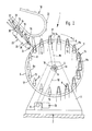
- This collecting device 1 has a frame 2 with bearing blocks 3, 3 ', in which the shaft 4 of a collecting drum 5 is mounted.
- Two disk-shaped bearing elements 6, 7 are fastened to this shaft 4 at a distance from one another, between which a number of collecting conveyors 8 are arranged, which are rotatably mounted in the bearing elements 6 and 7.
- These collecting conveyors 8 run parallel to one another and to the shaft 4 of the collecting drum 5 and are arranged around this shaft 4.
- a sprocket 9 On the shaft 4 there is a sprocket 9, over which a chain 10 is guided, which extends over another sprocket 11. The latter sits on the output shaft of one Drive 12, by means of which the collecting drum 5 together with the collecting conveyors 8 is driven in the direction of the arrow C.
- the axis of rotation is designated 4a.
- a simple embodiment of such guide means is shown schematically in FIG.
- a further sprocket 14 of the same size is also rotatably mounted.
- This sprocket 14 is in engagement with a chain 15 which is guided via a sprocket 16 which is fixedly and coaxially to the shaft 4 on the bearing block 3. All chain wheels 13 are in engagement with a chain 17 guided over this chain. This arrangement ensures that the collecting conveyors 8 maintain their vertical position during their rotation about the axis of rotation 4a.
- each feed conveyor has grippers 22 arranged at a mutual distance, the construction of which will be explained in more detail with reference to FIG. 3.
- each feed conveyor 18 Arranged below each feed conveyor 18 is an opening device 23, only shown schematically in FIG. 2, the structure of which will be described in more detail with reference to FIGS. 3 to 8.
- This opening device 23 has circumferential retaining clips 24 which, in a manner still to be explained, serve for the temporary detection of one part of the printed products 19.
- the printed products 19 fed by the feed conveyor 18 and opened by means of the opening device 23 are placed astride the collecting conveyor 8.
- Each collecting conveyor 8 is equipped with a conveyor device 25 (FIG. 1), not shown, which feeds the printed products 19, 20, 21 in the longitudinal direction of the collecting conveyor 8, ie in the direction of the arrow D.
- the drive of the conveyor device is preferably derived from the relative rotary movement between the individual collecting conveyors 8 and the bearing elements 6, 7.
- the feed speed of the conveying devices is selected such that each driver 25 travels a distance in the course of a revolution around the axis 4a, the length of which corresponds to the distance between adjacent feed conveyors 18 or opening devices 23.
- each gripper 22 has an upper jaw 27 and a lower, movable jaw 28.
- the grippers are pivotally mounted about a pivot axis designated 22a and have a control roller 29 which cooperates with a control cam 30 arranged on one side of the channel 26 in order to hold the grippers 22 in a desired pivot position.
- a further control cam 31 is arranged, which is intended to interact with a further control roller 32 connected to the movable clamping jaw 28.
- the control roller 32 running onto the cam 31 causes the movable clamping jaw 28 to pivot away from the upper clamping jaw 27 into a release position.
- the movable clamping jaw 28 is locked in a suitable manner, for example by means of a torsion spring, in its clamping position in which, together with the upper clamping jaw 27, they hold the printed products 19 on their fold 33.
- the grippers 22 are directed towards the front in the conveying direction E of the conveyor 18, that is to say they have an open mouth.
- the printed products 19 are therefore fed with their open side edge 34 opposite the fold 33 to the opening device 23 in advance.
- the printed products 19 are folded outside the middle, which means that one Product part 19a protrudes on said open side edge 34 above the other product part 19b.
- the projecting edge region of the product part 19a which is called the pre-fold, is designated by 35.
- the conveying direction E of the conveyor 18 is directed obliquely downward in the region of the opening device 23.
- the supplied printed products 19 also assume a position which slopes obliquely towards the front in their conveying direction E.
- the printed products 19 are fed in such a way that the product part 19a lies with the projecting edge section 35 on the underside.
- the retaining clips 24 of the opening device 23 are fastened at regular intervals to a chain 36 driven in rotation.
- the latter is guided over two sprockets 37 and 38, of which the sprocket 37 is driven such that the chain 36 rotates together with the retaining clips 24 in the direction of arrow F (FIG. 3).
- a drive chain 39 of the drive of the chain wheel 37 is shown purely schematically. With the sprocket 37 rotating, a deflection wheel 40 is connected, over which a round belt 41 is guided. The other deflection wheel for the endless belt 41 is not shown in FIG. 3.
- the direction of rotation of the belt 41 is designated G.
- the printed products 19 fed by the feed conveyor 19 come with their open side edge 34 to rest on the upper run of the belt 41 upstream of the opening device 23 and are thereby brought into the correct position for later clamping by the holding clamps 24.
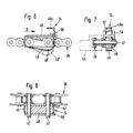
- FIGS. 4 and 5 in each of which only the left and right halves of the opening device are shown, two chains 36 arranged at a distance from one another and running parallel to one another are provided with retaining clips 24 attached to them. Accordingly, there are also two sprockets 37 and 38, respectively, which sit on shafts designated 42 and 43, respectively. The latter are rotatably supported in side bearing plates 44 and 45 (FIGS. 4 and 5). The chains 36 are guided in guides 46, as can be seen in particular from FIGS. 4 and 5.
- the retaining clips 24 are formed by a curved spring element fastened to the holder 48 at one end. At the other end, this spring element 49 is angled to a clamping finger 49a, as can be seen in FIG. 6.
- the spring element 49 is shown in broken lines in its lower rest or clamping position, which it assumes automatically due to its spring elasticity. From this lower rest position, the spring element 49 can be moved in a manner to be described into the upper receiving or release position, which is shown in FIG. 6 with solid lines.
- the retaining clips 24 run through longitudinal slots 50 and 51 in a support plate 52 (FIGS. 4 and 5).
- This support plate 52 has a straight section 52a and one in the direction of movement F of the retaining clips 24 seen subsequent curved section 52b.
- This curved section 52b runs at a distance around the chain wheel 38, as shown in FIG. 3.
- the support plate 52 is supported by supports 53 which are fastened to a cross member 54 which extends between the side plates 44 and 45 (FIGS. 4 and 5).
- the straight section 52a of the support plate 52 is arranged to drop downward in the direction of movement F of the retaining clips 24 and thus runs essentially in the same direction as the region of the movement path of the grippers 22 above the opening device 23.
- a control cam 55 is arranged below the straight section 52a of the support plate 52, onto which the retaining clips 24 run with a run-up surface 49 '(FIG. 6) of the spring elements 49 and which raise the spring elements 49 from the lower rest or clamping position to the upper one Release position causes.
- a fixed control cam 56 is provided adjacent to the sprocket 38 and, like the control cam 55, serves to lift the spring elements 49 from the lower clamping position into the upper release position.
- each spring element 49 On both sides of each spring element 49, two stop cams 57 and 58 are arranged, which are fastened to the holder 48. At these stop cams 57, 58, the printed products 19 come to a stop with their leading side edge 34 in a manner still to be described.
- the opening of the printed products 19 fed by the feed conveyor 18 by means of the opening device 23 is done in the following manner.
- the printed products 19 held by the grippers 22 on their fold 33 come with their leading side edge 34 to rest on the circumferential belt 41, as a result of which the printed products 19 are brought into an inclined position that slopes forward.
- the printed products 19 pass from the belt 41 onto the straight section 52a of the support plate 52, on which they rest with the projecting edge section 35 of the product part 19 below.
- the retaining clips 24 running in the direction of the arrow F slightly precede the leading side edges 34 of the printed products 19, as can be seen from FIG. 3.
- the spring elements 49 run onto the control cam 55, the spring elements 49 are moved from the lower rest position into the upper release position, in which they are ready to receive the projecting edge section 35.
- the grippers 22 of the conveyor 18 are opened briefly, as is shown in FIG. 3 with the aid of the gripper designated 22 '.
- the lifting of the movable jaw 28 from the upper jaw 27 is effected by running the control roller 32 on the cam 31.
- a pivoting of the grippers 22 about their pivot axis 22a is prevented by the control roller 29 being supported on the associated control cam 30.
- the printed product 19 'released by briefly opening the gripper 22' slides down into the open holding clamp 24 and comes with the edge of the projecting edge portion 35 on the spring element 49 or on the stop cams 57, 58 to the stop. Now the gripper 22 is brought back into its clamping position, with the result that the printed product 19 is held on its fold 33 again.
- the retaining clip 24 now comes outside the effective range of the control cam 55.
- the spring elements 49 which are assigned to one another, now move downward into the clamping position, in which they hold the projecting edge section 35, due to their spring elasticity.
- the retaining clips 24 together with the captured edge section 35 now reach the deflection area defined by the chain wheel 38 or the area of the curved section 52b of the support plate 52 of the support plate 52, while the printed product 19, which is still held by a gripper 22, is moved further by the conveyor 18. As a result, the held product part 19a is moved away from the other printed product part 19b and is thus separated.
- a revolving collecting conveyor 8 now moves into the opening O that is formed, as shown in FIG. 3.
- the captured edge section 35 can now be released. This now happens in that the spring elements 49 run with their contact surface 49 'onto the control cam 56 and are moved from the clamping position into the release position.
- the path of movement of the grippers 22 is now designed such that the opened printed products 19 assume a hanging position in which the two printed product parts 19a and 19b on different sides of a collecting conveyor 8 run.
- the control cam 31 now causes the grippers 22 to open and the released printed product 19 straddles the collecting conveyor 8 inserted between its two parts 19a and 19b.
- the printed products 19 which are placed on the latter become - as already shown in FIGS. 1 and 2 described - advanced in the longitudinal direction of the collecting conveyor 8 to the next opening device, in which another printed product 20 or 21 opened in the manner described is placed on the printed product 19 or 19 and 20 already located on the collecting conveyor 8.
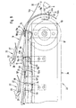
- the opening device 23 described can also be used essentially unchanged for opening printed products 19 which are fed in with the product part 19a having the projecting edge section 35 at the top. This will now be briefly explained with reference to FIG. 9, only the differences compared to the method of operation explained above with reference to FIG. 3 being discussed.
- the control curve 55 'for lifting the spring elements 49 into their release position is designed somewhat differently than the control curve 55 according to FIG. 3.
- the spring elements 49 are held in their lower rest position longer than in the exemplary embodiment according to FIG. 3 and only then lifted into the release position after the overhead printed product part 19a has come to a stop with its projecting edge section 35 on the stop cams 57, 58, as is shown in FIG. 9 with the aid of the printed product 19 'indicated by dash-dotted lines.
- the printed product 19 supplied with the above Edge section 35 on the stop cams 57, 58 the overhead printed product part 19a is raised in the region of the edge section 35 by lifting the spring elements 49.
- the printed product 19 is now advanced against the spring elements 49 until the edge region 59 of the shorter product part 19b lying below comes into the effective range of the clamping fingers 49a, ie until this edge region 59 on the spring elements 49 or the stop cams 57, 58 triggers.
- the spring elements 49 run off the control cam 55 ', they move automatically into the clamping position, in which the clamping fingers 49a hold the product part 19b located below in the region 59 of the leading side edge 34.
- the held product part 19b is now moved as described above along the curved section 52b of the support plate 52 and separated from the other product part 19a.
- a collecting conveyor 8 can intervene in the opening O formed in the process.
- stop cams 57, 58 are required for the opening of printed products 19 supplied overhead with their longer product part 19a, as described with reference to FIG. 9, these stop cams 57, 58 can be dispensed with in the embodiment according to FIG. 3 because the spring elements 49 also serve as a stop for the longer product part 19a below.
- This single collecting conveyor 8 can, for example, be a collecting chain be of conventional design.
- control curve 55 it is also possible to equip the opening devices 23 according to FIG. 3 with a control curve 55 ′ of the design shown in FIG. 9.
- suitable switching means depending on the type of supply of the printed products 19, one or the other control cam 55 or 55 'is brought into the operative position in which they interact with the spring elements 49.
- the supplied printed products 19, 20, 21 can be individual folded printed sheets or can also consist of a plurality of folded printed sheets lying one inside the other.
Abstract
Die zu öffnenden Druckprodukte (19) werden am Falz (33) gehalten und mit dem diesem gegenüberliegenden, offenen Seitenrand (34) vorauslaufend einer Oeffnungseinrichtung (23) zugeführt. Der untenliegende, mit einem vorstehenden Randabschnitt (35) versehene Produkteteil (19a) wird im Bereich des vorlaufenden Seitenrandes (34) durch umlaufend angetriebene Festhalteklammern (24) erfasst und entlang einer nach unten und rückwärts gekrümmten Bahn (52b) geführt. Gleichzeitig werden die Druckprodukte (19) durch den Zuförderer (18) weiterbefördert. Dabei werden die beiden Produkteteile (19a, 19b) voneinander getrennt. In die dabei gebildete Oeffnung (0) kann ein Sammelförderer (8) einer Sammeltrommel eingreifen, die eine Anzahl von umlaufenden Sammelförderern (8) aufweist. 
Description
Die vorliegende Erfindung betrifft ein Verfahren und eine Vorrichtung zum Oeffnen von ausserhalb der Mitte gefalteten Druckprodukten gemäss Oberbegriff des Anspruches 1 bzw. des Anspruches 6 sowie die Verwendung dieser Vorrichtung in einer Einrichtung zum Sammeln von ausserhalb der Mitte gefalteten Druckprodukten gemäss Oberbegriff des Anspruches 18.The present invention relates to a method and a device for opening printed products folded outside the center according to the preamble of
Bei einer bekannten Vorrichtung dieser Art werden die aussermittig gefalteten, zu öffnenden Druckprodukte mit ihrer Falzkante vorauslaufend in nach rückwärts abfallenden Schräglage zugeführt (EP-OS 0 095 603 und die entsprechende US-PS 4, 489,930). Dabei werden die Druckprodukte an dieser Falzkante durch bezüglich der Förderrichtung nach hinten weisende Greifer eines Förderers erfasst. Eine unterhalb des Förderers angeordnete Oeffnungseinrichtung ist mit umlaufend angetriebenen, gesteuerten Klammern ausgerüstet, welche dazu dienen, den vorstehenden Randabschnitt (Vorfalz genannt) am obenliegenden Teil der zugeführten Druckprodukte kurzzeitig festzuhalten. Dem Klammerrundlauf nachgeschaltet ist ein Beschleunigungsband, das mit höherer Geschwindigkeit als die Klammern umlaufend angetrieben ist. Sobald der durch die Klammern nicht festgehaltene, untenliegende Teil der Druckprodukte in den Wirkbereich dieses Beschleunigungsbandes gelangt, wird dieser Produkteteil infolge Reibschluss vom Beschleunigungsband mitgenommen und vom obenliegenden, durch die Klammern gehaltenen Produkteteil getrennt. Die derart geöffneten Druckprodukte werden dann auf umlaufende Auflagestege einer Sammeleinrichtung fallengelassen, auf denen die Druckprodukte rittlings zur Auflage kommen.In a known device of this type, the eccentrically folded, openable printed products are fed with their folded edge leading in a backward sloping position (EP-
Diese bekannte Lösung ist nun aufwendig in der Konstruktion, wird doch neben dem Klammerrundlauf auch ein Beschleunigungsband benötigt. Da das Trennen der Produktehälften, d.h. das Oeffnen der Druckprodukte, von der Reibungsmitnahme des einen Druckprodukteteils durch das Beschleunigungsband abhängt, ist ein sicheres Oeffnen unter allen Bedingungen nicht gewährleistet, insbesondere dann nicht, wenn die beiden Produkteteile stärker als üblich aneinander haften.This known solution is now complex to construct, since an acceleration belt is also required in addition to the concentric runout. Since separating the product halves, i.e. the opening of the printed products, which depends on the frictional dragging of the one printed product part by the acceleration belt, does not guarantee safe opening under all conditions, especially not when the two product parts adhere to one another more than usual.
Der vorliegenden Erfindung liegt nun die Aufgabe zugrunde, ein Verfahren und eine Vorrichtung der eingangs genannten Art zu schaffen, das bzw. die auf einfache Weise ein sicheres Oeffnen der Druckprodukte ermöglicht.The present invention is based on the object of providing a method and a device of the type mentioned at the outset which, in a simple manner, enable the printed products to be opened safely.
Diese Aufgabe wird erfindungsgemäss durch die Merkmale des kennzeichnenden Teils des Anspruches 1 bzw. des Anspruches 6 gelöst.This object is achieved according to the invention by the features of the characterizing part of
Da die Druckprodukte mit ihrer dem Falz gegenüberliegenden, offenen Seitenkante, an der der eine Produkteteil über den anderen Produkteteil vorsteht, vorauslaufend zugeführt werden, ist ein sicheres Erfassen des einen Produkteteils durch die Festhalteorgane möglich, weil der zu erfassende Produkteteil ohne Schwierigkeiten in den Wirkbereich der Festhalteorgane eingebracht werden kann. Der erfasste Druckprodukteteil wird dann entlang einer vorzugsweise nach unten und rückwärts gekrümmten Bahn vom andern Druckprodukteteil wegbewegt, während das Druckprodukt und damit auch der zuletzt genannte, andere Druckprodukteteil durch den Förderer weitergefördert wird. Dadurch wird ein Separieren der beiden Druckprodukteteile auch dann gewährleistet, wenn diese stärker als gewöhnlich aneinander haften sollten. Bevorzugte Weiterausgestaltungen des Erfindungsgegenstandes sind in den abhängigen Ansprüchen 2 - 5 und 7 - 17 umschrieben.Since the printed products are fed in advance with their open side edge opposite the fold, on which one product part protrudes over the other product part, it is possible to securely grasp the one product part by means of the holding elements, because the product part to be detected can easily be caught in the effective range of the Retaining organs can be introduced. The captured printed product part is then moved along a path that is preferably curved downwards and backwards moves another part of the printed product away, while the printed product and thus also the last-mentioned other printed product part is conveyed further by the conveyor. This ensures that the two printed product parts are separated even if they stick together more than usual. Preferred further developments of the subject matter of the invention are described in the dependent claims 2-5 and 7-17.
Die erfindungsgemäss Oeffnungsvorrichtung eignet sich insbesondere für den Einsatz in einer Einrichtung zum Sammeln von ausserhalb der Mitte gefalteten Druckprodukten gemäss den Ansprüchen 18 und 19.The opening device according to the invention is particularly suitable for use in a device for collecting printed products folded outside the center according to
Im folgenden wird der Erfindungsgegenstand anhand der Zeichnung näher beschrieben. Es zeigt rein schematisch:
- Fig. 1 eine Sammelvorrichtung in perspektivischer Ansicht,
- Fig. 2 die Sammelvorrichtung gemäss
Figur 1 in Stirnansicht, - Fig. 3 in Seitenansicht eine Oeffnungsvorrichtung und ein Teil eines Förderers,
- Fig. 4 eine Ansicht, teilweise im Schnitt, der Oeffnungsvorrichtung in Richtung des Pfeiles A in Fig. 3,
- Fig. 5 einen Schnitt entlang der Linie V-V in Fig. 3,
- Fig. 6 ein Festhalteorgan in Seitenansicht und teilweise im Schnitt,
- Fig. 7 das Festhalteorgan gemäss Fig. 6 in Vorderansicht in Richtung des Pfeiles B in Fig. 6 und teilweise im Schnitt,
- Fig. 8 das Festhalteorgan gemäss Fig. 6 in Draufsicht und teilweise im Schnitt, und
- Fig. 9 in einer der Fig. 3 ähnlichen Darstellung eine andere Ausführungsform einer Oeffnungseinrichtung.
- 1 is a perspective view of a collecting device,
- 2 the front end of the collecting device according to FIG. 1,
- 3 is a side view of an opening device and part of a conveyor,
- 4 is a view, partly in section, of the opening device in the direction of arrow A in FIG. 3,
- 5 shows a section along the line VV in FIG. 3,
- 6 is a holding member in side view and partially in section,
- 7 is a front view in the direction of arrow B in Fig. 6 and partially in section,
- Fig. 8, the holding member of FIG. 6 in plan view and partially in section, and
- FIG. 9 shows another embodiment of an opening device in a representation similar to FIG. 3.
Anhand der Figuren 1 und 2 wird nun die mit 1 bezeichnete Sammelvorrichtung erläutert, die Gegenstand der schweizerischen Patentanmeldung Nr. 2828/85-5 bildet und in letzterer ausführlicher beschrieben ist.With reference to Figures 1 and 2, the collecting device designated 1 is now explained, which is the subject of the Swiss patent application No. 2828 / 85-5 and is described in more detail in the latter.
Diese Sammelvorrichtung 1 weist ein Gestell 2 mit Lagerböcken 3, 3' auf, in denen die Welle 4 einer Sammeltrommel 5 gelagert ist. Auf dieser Welle 4 sind in einem Abstand voneinander zwei scheibenförmige Lagerelemente 6, 7 befestigt, zwischen denen eine Anzahl von Sammelförderern 8 angeordnet ist, die in den Lagerelementen 6 und 7 drehbar gelagert sind. Diese Sammelförderer 8 verlaufen parallel zueinander und zur Welle 4 der Sammeltrommel 5 und sind um diese Welle 4 herum angeordnet.This
Auf der Welle 4 sitzt ein Kettenrad 9, über das eine Kette 10 geführt ist, die über ein weiteres Kettenrad 11 verläuft. Letzteres sitzt auf der Abtriebswelle eines Antriebes 12, mittels dem die Sammeltrommel 5 samt den Sammelförderern 8 in Richtung des Pfeiles C umlaufend angetrieben wird. Die Umlaufachse ist mit 4a bezeichnet.On the shaft 4 there is a sprocket 9, over which a
Die Sammelförderer 8, die - wie Fig. 2 zeigt - satteldachförmig ausgebildet sind, werden durch geeignete Führungsmittel während ihres Umlaufes um die Umlaufachse 4a derart um ihre Längsachse gedreht, dass sie mit ihrem First 8a stets nach oben weisen. In Fig. 2 ist eine einfache Ausführungsform derartiger Führungsmittel schematisch gezeigt. Am einen Ende jedes der Sammelförderer 8 is ein Kettenrad 13 drehfest mit dem Sammelförderer montiert. An einem der Sammelförderer, der mit 8' bezeichnet ist, ist ein weiteres, gleich grosses Kettenrad 14 ebenfalls drehfest montiert. Dieses Kettenrad 14 steht im Eingriff mit einer Kette 15, die über ein fest und koaxial zur Welle 4 am Lagerbock 3 angebrachtes Kettenrad 16 geführt ist. Alle Kettenräder 13 stehen im Eingriff mit einer über diese geführte Kette 17. Durch diese Anordnung wird erreicht, dass die Sammelförderer 8 während ihres Umlaufes um die Drehachse 4a ihre vertikale Lage beibehalten.The
In Richtung der Längsachse der Welle 4 gesehen sind hintereinander drei Zuförderer 18 für gefalzte Druckprodukte 19, 20, 21 angeordnet. In Förderrichtung D der Sammelförderer 8 gesehen hinter dem letzten Zuförderer 18 ist ein nur schematisch dargestellter Wegförderer W angeordnet, der die aus mehreren übereinanderliegenden Druckbogen bestehenden Endprodukte P wegführt.Viewed in the direction of the longitudinal axis of the shaft 4, three
Wie aus Fig. 2 hervorgeht, in der der vorderste der gleich aufgebauten Zuförderer 18 dargestellt ist, weist jeder Zuförderer in einem gegenseitigen Abstand angeordnete Greifer 22 auf, deren Konstruktion anhand der Fig. 3 noch näher erläutert werden wird.As can be seen from FIG. 2, in which the
Unterhalb jedes Zuförderers 18 ist eine in Fig. 2 nur schematisch dargestellte Oeffnungseinrichtung 23 angeordnet, deren Aufbau anhand der Figuren 3 bis 8 noch genauer zu beschreiben sein wird. Diese Oeffnungseinrichtung 23 weist umlaufende Festhalteklammern 24 auf, die auf noch zu erläuternde Weise zum vorübergehenden Erfassen des einen Teils der Druckprodukte 19 dienen.Arranged below each
Die durch die Zuförderer 18 zugeführten und mittels der Oeffnungseinrichtung 23 geöffneten Druckprodukte 19 werden rittlings auf die Sammelförderer 8 aufgelegt. Jeder Sammelförderer 8 ist mit einer mit Mitnehmern 25 (Fig. 1) versehenen, nicht näher dargestellten Fördervorrichtung ausgerüstet, die die aufgelegten Druckprodukte 19, 20, 21 in Längsrichtung der Sammelförderer 8, d.h. in Richtung des Pfeiles D, vorschiebt. Der Antrieb der Fördervorrichtung wird vorzugsweise von der Relativdrehbewegung zwischen den einzelnen Sammelförderern 8 und den Lagerelementen 6, 7 abgeleitet. Die Vorschubgeschwindigkeit der Fördervorrichtungen ist so gewählt, dass jeder Mitnehmer 25 im Zuge eines Umlaufes um die Achse 4a eine Strecke zurücklegt, dessen Länge dem Abstand benachbarter Zuförderer 18 bzw. Oeffnungseinrichtungen 23 entspricht.The printed
Im folgenden wird nun anhand der Figuren 3 bis 9 der Aufbau der Förderer 18 und der Oeffnungseinrichtung 23 und das Oeffnen der zugeführten Druckprodukte 19 näher erläutert.The structure of the
Wie aus Fig. 3 hervorgeht, sind die Greifer 22 des Zuförderers 18 an einen in einem Kanal 26 geführten, umlaufend angetriebenen Zugorgan befestigt, das nicht näher dargestellt ist. Jeder Greifer 22 weist eine obere Klemmbacke 27 und eine untere, bewegliche Klemmbacke 28 auf. Die Greifer sind um eine mit 22a bezeichnete Schwenkachse schwenkbar gelagert und weisen eine Steuerrole 29 auf, welche mit einer auf der einen Seite des Kanals 26 angeordneten Steuerkurve 30 zusammenwirkt, um die Greifer 22 in einer gewünschten Schwenklage zu halten. Auf der andern Seite des Kanals 26 ist eine weitere Steuerkurve 31 angeordnet, die dazu bestimmt ist, mit einer mit der beweglichen Klemmbacke 28 verbundenen weiteren Steuerrolle 32 zusammenzuwirken. Durch die auf die Steuerkurve 31 auflaufende Steuerrolle 32 wird ein Verschwenken der beweglichen Klemmbacke 28 von der oberen Klemmbacke 27 weg in eine Freigabestellung bewirkt. Die bewegliche Klemmbacke 28 wird auf geeignete Weise, z.B. mittels einer Torsionsfeder, in ihrer Klemmstellung verriegelt, in der sie zusammen mit der oberen Klemmbacke 27 die Druckprodukte 19 an derem Falz 33 festhalten. Die Greifer 22 sind in Förderrichtung E des Förderers 18 gesehen nach vorn gerichtet, d.h. weisen ein nach vorne offenes Maul auf. Die Druckprodukte 19 werden daher mit ihrer dem Falz 33 gegenüberliegenden, offenen Seitenkante 34 vorauslaufend der Oeffnungseinrichtung 23 zugeführt. Die Druckprodukte 19 sind ausserhalb der Mitte gefaltet, was bedeutet, dass der eine Produkteteil 19a an der genannten offenen Seitenkante 34 über den anderen Produkteteil 19b vorsteht. Der vorstehende Randbereich des Produkteteiles 19a, der Vorfalz genannt wird, ist mit 35 bezeichnet. Die Förderrichtung E des Förderers 18 ist im Bereich der Oeffnungsvorrichtung 23 schräg nach unten gerichtet. Die zugeführten Druckprodukte 19 nehmen ebenfalls eine in ihrer Förderrichtung E gesehen schräg nach vorne abfallende Lage ein. Bei der Ausführungsform gemäss Fig. 3 werden die Druckprodukte 19 so zugeführt, dass der Produkteteil 19a mit dem vorstehenden Randabschnitt 35 auf der Unterseite liegt.As can be seen from FIG. 3, the
Die Festhalteklammern 24 der Oeffnungsvorrichtung 23, deren Aufbau im folgenden anhand der Figuren 3 bis 8 erläutert wird, sind in regelmässigen Abständen an einer umlaufend angetriebenen Kette 36 befestigt. Letztere ist über zwei Kettenräder 37 und 38 geführt, von denen das Kettenrad 37 derart angetrieben ist, dass die Kette 36 samt den Festhalteklammern 24 in Richtung des Pfeiles F (Fig. 3) umläuft. Vom Antrieb des Kettenrades 37 ist nur rein schematisch eine Antriebskette 39 gezeigt. Mit dem Kettenrad 37 mitdrehend ist ein Umlenkrad 40 verbunden, über das ein Rundriemen 41 geführt ist. Das andere Umlenkrad für den Endlosriemen 41 ist in Fig. 3 nicht dargestellt. Die Umlaufrichtung des Riemens 41 ist mit G bezeichnet. Die durch den Zuförderer 19 zugeführten Druckprodukte 19 kommen mit ihrem offenen Seitenrand 34 auf dem oberen Trum des der Oeffnungsvorrichtung 23 vorgeschalteten Riemens 41 zur Auflage und werden dadurch in die für eine spätere Klemmung durch die Festhalteklammern 24 richtige Lage gebracht.The retaining clips 24 of the
Wie aus den Figuren 4 und 5, in denen jeweils nur die linke bzw. die rechte Hälfte der Oeffnungsvorrichtung dargestellt ist, hervorgeht, sind zwei in einem Abstand zueinander angeordnete und parallel zueinander verlaufende Ketten 36 mit an diesen angebrachten Festhalteklammern 24 vorgesehen. Dementsprechend sind auch zwei Kettenräder 37 bzw. 38 vorhanden, die auf mit 42 bzw. 43 bezeichneten Wellen sitzen. Letztere sind in seitlichen Lagerplatten 44 und 45 (Fig. 4 und 5) drehbar gelagert. Die Ketten 36 sind in Führungen 46 geführt, wie das insbesondere aus den Figuren 4 und 5 hervorgeht.As can be seen from FIGS. 4 and 5, in each of which only the left and right halves of the opening device are shown, two
An den Ketten 36 sind nach der Seite hin vorstehende Haltebolzen 47 befestigt, auf denen eine Halterung 48 für die Festhalteklammern 24 sitzt (siehe insbesondere die Fig. 7 und 8). Die Festhalteklammern 24 werden durch ein gebogenes, am einen Ende an der Halterung 48 befestigtes Federelement gebildet. Am andern Ende ist dieses Federelement 49 zu einem Klemmfinger 49a abgewinkelt, wie das aus Fig. 6 hervorgeht. In dieser Figur ist das Federelement 49 strichpunktiert in seiner untern Ruhe- bzw. Klemmstellung gezeigt, die es infolge seiner Federelastizität selbsttätig einnimmt. Aus dieser unteren Ruhestellung kann das Federelement 49 auf noch zu beschreibende Weise in die obere Aufnahme- oder Freigabestellung bewegt werden, die in Fig. 6 mit ausgezogenen Linien dargestellt ist.On the
Die Festhalteklammern 24 verlaufen durch Längsschlitze 50 und 51 in einem Auflageblech 52 (Fig. 4 und 5). Dieses Auflageblech 52 weist einen geraden Abschnitt 52a und einen in Bewegungsrichtung F der Festhalteklammern 24 gesehen anschliessenden gekrümmten Abschnitt 52b auf. Dieser gekrümmte Abschnitt 52b verläuft in einem Abstand um das Kettenrad 38 herum, wie das Fig. 3 zeigt. Das Auflageblech 52 wird durch Abstützungen 53 getragen, die an einem Querträger 54 befestigt sind, der sich zwischen den Seitenschildern 44 und 45 erstreckt (Fig. 4 und 5). Der gerade Abschnitt 52a des Auflagebleches 52 ist in Bewegungsrichtung F der Festhalteklammern 24 gesehen nach unten abfallend angeordnet und verläuft somit im wesentlichen in derselben Richtung wie der oberhalb der Oeffnungsvorrichtung 23 liegende Bereich der Bewegungsbahn der Greifer 22.The retaining clips 24 run through longitudinal slots 50 and 51 in a support plate 52 (FIGS. 4 and 5). This
Unterhalb des geraden Abschnittes 52a des Auflagebleches 52 ist eine Steuerkurve 55 angeordnet, auf die die Festhalteklammern 24 mit einer Auflauffläche 49' (Fig. 6) der Federelemente 49 auflaufen und die ein Anheben der Federelemente 49 von der unteren Ruhe- oder Klemmstellung in die obere Freigabestellung bewirkt. Benachbart zum Kettenrad 38 ist ein feststehender Steuernocken 56 vorgesehen, der gleich wie die Steuerkurve 55 zum Anheben der Federelemente 49 aus der untern Klemmstellung in die obere Freigabestellung dient.A
Beidseits jedes Federelementes 49 sind zwei Anschlagnocken 57 und 58 angeordnet, die an der Halterung 48 befestigt sind. An diesen Anschlagnocken 57, 58 kommen die Druckprodukte 19 auf noch zu beschreibende Weise mit ihrer vorlaufenden Seitenkante 34 zum Anschlag.On both sides of each
Das Oeffnen der durch den Zuförderer 18 zugeführten Druckprodukte 19 mittels der Oeffnungsvorrichtung 23 erfolgt auf die nachstehend erläuterte Weise.The opening of the printed
Die durch die Greifer 22 an ihrem Falz 33 festgehaltenen Druckprodukte 19 gelangen mit ihrer vorlaufenden Seitenkante 34 zur Auflage auf den umlaufenden Riemen 41, wodurch die Druckprodukte 19 in eine nach vorn abfallende Schräglage gebracht werden. Die Druckprodukte 19 gelangen vom Riemen 41 auf den geraden Abschnitt 52a des Auflagebleches 52, auf dem sie mit dem vorstehenden Randabschnitt 35 des untenliegenden Produkteteiles 19 aufliegen. Die in Richtung des Pfeiles F umlaufenden Festhalteklammern 24 laufen den vorlaufenden Seitenkanten 34 der Druckprodukte 19 etwas vor, wie das aus Fig. 3 hervorgeht. Beim Auflaufen der Federelemente 49 auf die Steuerkurve 55 werden die Federelemente 49 aus der untern Ruhestellung in die obere Freigabestellung bewegt, in der sie zur Aufnahme des vorstehenden Randabschnittes 35 bereit sind. Um nun diesen vorstehenden Randabschnitt 35 sicher in den Wirkbereich der Klemmfinger 49a der Federelemente 49 zu bringen, werden die Greifer 22 des Förderers 18 kurzzeitig geöffnet, wie das in Fig. 3 anhand des mit 22' bezeichneten Greifers dargestellt ist. Das Abheben der beweglichen Klemmbacke 28 von der oberen Klemmbacke 27 wird dabei durch Auflaufen der Steuerrolle 32 auf der Steuerkurve 31 bewirkt. Ein Verschwenken der Greifer 22 um ihre Schwenkachse 22a wird dadurch verhindert, dass die Steuerrolle 29 sich auf der zugeordneten Steuerkurve 30 abstützt.The printed
Das durch kurzzeitiges Oeffnen des Greifers 22' freigegebene Druckprodukt 19' rutscht nach unten in die offene Festhalteklammer 24 hinein und kommt mit der Kante des vorstehenden Randabschnittes 35 am Federelement 49 bzw. an den Anschlagnocken 57, 58 zum Anschlag. Nun wird der Greifer 22 wieder in seine Klemmstellung gebracht, was zur Folge hat, dass das Druckprodukt 19 wieder an seinem Falz 33 festgehalten wird. Nun gelangt die Festhalteklammer 24 ausserhalb des Wirkbereiches der Steuerkurve 55. Die einander zugeordneten Federelemente 49 bewegen sich nun infolge ihrer Federelastizität nach unten in die Klemmstellung, in der sie den vorstehenden Randabschnitt 35 festhalten. Die Festhalteklammern 24 samt dem erfassten Randabschnitt 35 gelangen nun in den durch das Kettenrad 38 festgelegten Umlenkbereich bzw. in den Bereich des gekrümmten Abschnittes 52b des Auflagebleches 52. Der festgehaltene vorstehende Randabschnitt 35 sowie dessen benachbarter Bereich des Produkteteiles 19a wird nun entlang des gekrümmten Abschnittes 52b des Auflagebleches 52 geführt, während das nach wie vor durch einen Greifer 22 festgehaltene Druckprodukt 19 durch den Förderer 18 weiterbewegt wird. Das hat zur Folge, dass der festgehaltene Produkteteil 19a vom andern Druckprodukteteil 19b wegbewegt und somit getrennt wird. In die sich dabei bildende Oeffnung O fährt nun ein wie beschrieben umlaufender Sammelförderer 8 ein, wie das Fig. 3 zeigt. Der festgehaltene Randabschnitt 35 kann nun freigegeben werden. Das geschieht nun dadurch, dass die Federelemente 49 mit ihrer Auflauffläche 49' auf den Steuernocken 56 auflaufen und von der Klemmstellung in die Freigabestellung bewegt werden.The printed product 19 'released by briefly opening the gripper 22' slides down into the open holding
Die Bewegungsbahn der Greifer 22 ist nun so ausgebildet, dass die geöffneten Druckprodukte 19 eine hängende Lage einnehmen, in der die beiden Druckprodukteteile 19a und 19b auf verschiedenen Seiten eines Sammelförderers 8 verlaufen. Durch die Steuerkurve 31 wird nun ein Oeffnen der Greifer 22 bewirkt und das freigegebene Druckprodukt 19 fällt rittlings auf den zwischen seine beiden Teile 19a und 19b eingefahrenen Sammelförderer 8. Die auf letzteren zur Auflage kommenden Druckprodukte 19 werden - wie bereits anhand der Figuren 1 und 2 beschrieben - in Längsrichtung der Sammelförderer 8 zur nächsten Oeffnungsvorrichtung vorgeschoben, in der ein weiteres auf die beschriebene Art geöffnetes Druckprodukt 20 bzw. 21 auf das sich bereits auf dem Sammelförderer 8 befindliche Druckprodukt 19 bzw. 19 und 20 aufgelegt wird.The path of movement of the
Die beschriebene Oeffnungsvorrichtung 23 kann im wesentlichen unverändert auch zum Oeffnen von Druckprodukten 19 verwendet werden, welche mit dem den vorstehenden Randabschnitt 35 aufweisenden Produkteteil 19a obenliegend zugeführt werden. Dies soll nun anhand der Fig. 9 kurz erläutert werden, wobei nur auf die Unterschiede gegenüber der vorstehend anhand der Fig. 3 erläuterten Funktionzweise eingegangen wird.The
Die Steuerkurve 55' zum Anheben der Federelemente 49 in ihre Freigabestellung ist etwas anders augebildet als die Steuerkurve 55 gemäss Fig. 3. Die Federelemente 49 werden nämlich länger als beim Ausführungsbeispiel gemäss Fig. 3 in ihrer untern Ruhelage gehalten und erst dann in die Freigabestellung angehoben, nachdem der obenliegende Druckprodukteteil 19a mit seinem vorstehenden Randabschnitt 35 an den Anschlagnocken 57, 58 zum Anschlag gekommen ist, wie das in Fig. 9 anhand des strichpunktiert angedeuteten Druckproduktes 19' dargestellt ist. Steht nun das zugeführte Druckprodukt 19 mit dem vorstehenden Randabschnitt 35 an den Anschlagnocken 57, 58 an, so wird durch Anheben der Federelemente 49 der obenliegende Druckprodukteteil 19a im Bereich des Randabschnittes 35 angehoben. Durch kurzzeitiges Oeffnen der Greifer 22 wird nun das Druckprodukt 19 gegen die Federelemente 49 vorgeschoben, bis der Randbereich 59 des untenliegenden, kürzeren Produkteteiles 19b in den Wirkbereich der Klemmfinger 49a kommt, d.h. bis dieser Randbereich 59 an den Federelementen 49 bzw. den Anschlagnocken 57, 58 anstösst. Sobald die Federelemente 49 von der Steuerkurve 55' ablaufen, bewegen sie sich selbsttätig in die Klemmstellung, in der die Klemmfinger 49a den untenliegenden Produkteteil 19b im Bereich 59 des vorlaufenden Seitenrandes 34 festhalten. Der festgehaltene Produkteteil 19b wird nun wie vorstehend beschrieben entlang des gekrümmten Abschnittes 52b des Auflagebleches 52 bewegt und vom andern Produkteteil 19a getrennt. In die dabei gebildete Oeffnung O kann ein Sammelförderer 8 eingreifen.The control curve 55 'for lifting the
Während die Anschlagnocken 57, 58 für das anhand der Fig. 9 beschriebene Oeffnen von mit ihrem längern Produkteteil 19a obenliegend zugeführte Druckprodukten 19 erforderlich sind, kann bei der Ausführungsform gemäss Fig. 3 unter Umständen auf diese Anschlagnocken 57, 58 verzichtet werden, da die Federelemente 49 auch als Anschlag für den untenliegenden längern Produkteteil 19a dienen.While the
Anstelle von wie anhand der Figuren 1 und 2 beschrieben umlaufenden Sammelförderern8 ist es auch denkbar, nur einen einzigen feststehenden Sammelförderer 8 zu verwenden, auf den die Druckprodukte 19, 20, 21 auf die beschriebene Weise aufgelegt werden. Dieser einzige Sammelförderer 8 kann dabei beispielsweise als Sammelkette herkömmlicher Bauart ausgebildet sein.Instead of revolving
Im weiteren ist es möglich, die Oeffnungseinrichtungen 23 gemäss Fig. 3 zusätzlich zur Steuerkurve 55 noch mit einer Steuerkurve 55' der in Fig. 9 gezeigten Ausbildung auszurüsten. Durch geeignete Umschaltmittel wird dann je nach der Art der Zuführung der Druckprodukte 19 jeweils die eine oder die andere Steuerkurve 55 bzw. 55' in die Wirkstellung gebracht, in der sie mit den Federelementen 49 zusammenwirken. Mit einer solchen Ausführungsform ist es möglich, Druckprodukte 19 zu öffnen, die entweder mit dem den vorstehenden Randabschnitt 35 aufweisenden Produkteteil 19a obenliegend oder untenliegend zugeführt werden.In addition to the
Die zugeführten Druckprodukte 19, 20, 21 können einzelne gefaltete Druckbogen sein oder auch aus mehreren ineinanderliegenden gefalteten Druckbogen bestehen.The supplied printed
Claims (19)
Priority Applications (1)
| Application Number | Priority Date | Filing Date | Title |
|---|---|---|---|
| AT86106243T ATE37013T1 (en) | 1985-07-01 | 1986-05-07 | METHOD AND DEVICE FOR OPENING PRINTED PRODUCTS FOLDED OFF-CENTER. |
Applications Claiming Priority (4)
| Application Number | Priority Date | Filing Date | Title |
|---|---|---|---|
| CH2828/85A CH667620A5 (en) | 1985-07-01 | 1985-07-01 | METHOD AND DEVICE FOR COLLECTING FOLDED PRINTED SHEETS. |
| CH2828/85 | 1985-07-01 | ||
| CH3245/85 | 1985-07-26 | ||
| CH324585A CH668408A5 (en) | 1985-07-26 | 1985-07-26 | Opening system for eccentrically folded printed signatures |
Publications (2)
| Publication Number | Publication Date |
|---|---|
| EP0208081A1 true EP0208081A1 (en) | 1987-01-14 |
| EP0208081B1 EP0208081B1 (en) | 1988-09-07 |
Family
ID=25691494
Family Applications (1)
| Application Number | Title | Priority Date | Filing Date |
|---|---|---|---|
| EP86106243A Expired EP0208081B1 (en) | 1985-07-01 | 1986-05-07 | Method and device for opening eccentrically folded printing products |
Country Status (7)
| Country | Link |
|---|---|
| US (1) | US4684117A (en) |
| EP (1) | EP0208081B1 (en) |
| JP (1) | JPH06102497B2 (en) |
| AU (1) | AU576297B2 (en) |
| CA (1) | CA1264167A (en) |
| DE (1) | DE3660669D1 (en) |
| FI (1) | FI80002C (en) |
Cited By (9)
| Publication number | Priority date | Publication date | Assignee | Title |
|---|---|---|---|---|
| EP0518063A1 (en) * | 1991-06-10 | 1992-12-16 | Ferag AG | Method and apparatus for opening and placing folded printed products on a saddle-shaped support |
| EP0518064A1 (en) * | 1991-06-10 | 1992-12-16 | Ferag AG | Method and apparatus for handling of printed products |
| EP0522319A1 (en) * | 1991-07-11 | 1993-01-13 | Ferag AG | Method and device for opening flexible articles folded off-centre |
| EP0564812A1 (en) * | 1992-04-06 | 1993-10-13 | Ferag AG | Method and device for opening folded printing products |
| CH684085A5 (en) * | 1991-12-04 | 1994-07-15 | Ferag Ag | Automatic unfolding of folded printed sheets |
| EP0647582A1 (en) * | 1993-10-08 | 1995-04-12 | Ferag AG | Device for opening and further conveying printed products |
| US5462266A (en) * | 1992-12-04 | 1995-10-31 | Ferag Ag | Process and apparatus for opening folded printed products |
| EP0721903A1 (en) * | 1995-01-13 | 1996-07-17 | Ferag AG | Device for opening printed products and apparatus for handling printed products |
| CH687872A5 (en) * | 1994-08-17 | 1997-03-14 | Ferag Ag | A process for the continuous production of various types of printed products from different printed printing product parts. |
Families Citing this family (17)
| Publication number | Priority date | Publication date | Assignee | Title |
|---|---|---|---|---|
| ES2037311T3 (en) * | 1988-05-11 | 1993-06-16 | Ferag Ag | DEVICE FOR THE HANDLING OF PRINTED PRODUCTS. |
| DE58900823D1 (en) * | 1988-05-11 | 1992-03-26 | Ferag Ag | FACILITIES FOR GATHERING, INSERTING AND COLLECTING PRINT PRODUCTS. |
| ATE85028T1 (en) * | 1988-05-11 | 1993-02-15 | Ferag Ag | DEVICE FOR COLLECTING FOLDED SHEET. |
| IT1219354B (en) * | 1988-06-03 | 1990-05-11 | Smyth Europ Ind Spa | Feeding signatures in book sewing machine |
| ATE81098T1 (en) * | 1988-06-14 | 1992-10-15 | Ferag Ag | EQUIPMENT FOR COLLECTING, COLLATING AND INSERTING PRINTED PRODUCTS. |
| CH682911A5 (en) * | 1988-08-11 | 1993-12-15 | Ferag Ag | A method for producing the multi-part printed products, prepared by this process printed product and apparatus for performing the method. |
| US5137409A (en) * | 1989-07-21 | 1992-08-11 | Ferag Ag | Joining together of printed partial products |
| EP0510525B1 (en) * | 1991-04-26 | 1994-12-07 | Ferag AG | Method and device for handling printed products |
| JP2696633B2 (en) * | 1991-11-05 | 1998-01-14 | ホリゾン・インターナショナル株式会社 | Collator |
| EP0662440B1 (en) * | 1994-01-10 | 1997-07-02 | Ferag AG | Device for adhesively stapling printed articles |
| ATE149923T1 (en) * | 1994-01-19 | 1997-03-15 | Ferag Ag | METHOD AND DEVICE FOR ADHESIVELY BONDING THE SHEETS OF A MULTI-SHEET FOLDED PRINTED PRODUCT |
| DE59506062D1 (en) * | 1994-03-08 | 1999-07-08 | Ferag Ag | Device for producing multi-part printed products |
| CH690576A5 (en) * | 1995-06-30 | 2000-10-31 | Ferag Ag | Apparatus for processing printing products. |
| CH689864A5 (en) * | 1995-06-30 | 1999-12-31 | Ferag Ag | Apparatus for processing printing products. |
| DK0831045T3 (en) * | 1996-09-06 | 2002-02-11 | Ferag Ag | Method and apparatus for opening flexible flat products |
| DK1277685T3 (en) | 2001-07-18 | 2006-01-23 | Ferag Ag | Method and device for transforming a stream of flat objects |
| EP1475339A1 (en) * | 2003-05-08 | 2004-11-10 | MASCHINENBAU OPPENWEILER BINDER GmbH & Co. KG | Method and device for the further treatment of printed products |
Citations (4)
| Publication number | Priority date | Publication date | Assignee | Title |
|---|---|---|---|---|
| GB512870A (en) * | 1938-03-24 | 1939-09-27 | Brehmer Geb | Improvements in and relating to the feeding of folded signatures to book-stitching and like machines |
| US2969981A (en) * | 1958-06-13 | 1961-01-31 | Time Inc | Signature handling apparatus |
| US3481594A (en) * | 1967-07-10 | 1969-12-02 | Chicago Machinery Lab Inc | Signature feeding apparatus |
| EP0095603A1 (en) * | 1982-06-01 | 1983-12-07 | Ferag AG | Device for collecting folded printing sheets |
Family Cites Families (9)
| Publication number | Priority date | Publication date | Assignee | Title |
|---|---|---|---|---|
| CH591382A5 (en) * | 1974-05-28 | 1977-09-15 | Ferag Ag | |
| CH586611A5 (en) * | 1975-11-14 | 1977-04-15 | Grapha Holding Ag | |
| SE413007B (en) * | 1977-04-12 | 1980-03-31 | Wifag Maschf | DEVICE FOR CREATING A CURRENT OF OVERLAPPED FALSE PRINTED PRODUCTS |
| US4126390A (en) * | 1977-05-02 | 1978-11-21 | Eastman Kodak Company | Job stream programmer apparatus |
| CH618398A5 (en) * | 1977-06-06 | 1980-07-31 | Ferag Ag | |
| CH630583A5 (en) * | 1978-06-30 | 1982-06-30 | Ferag Ag | DEVICE FOR MOVING AWAY OF FLAT PRODUCTS INCLUDING IN A DOMESTIC FLOW, IN PARTICULAR PRINTED PRODUCTS. |
| CH644814A5 (en) * | 1980-01-08 | 1984-08-31 | Ferag Ag | METHOD AND DEVICE FOR OPENING FOLDED, BINDED OR STAPLED MULTI-SHEET PRODUCTS, IN PARTICULAR PRINTED PRODUCTS. |
| US4555101A (en) * | 1984-03-13 | 1985-11-26 | Stobb, Inc. | Method and apparatus for separating signatures from a stack |
| US4641825A (en) * | 1985-05-22 | 1987-02-10 | Harris Graphics Corporation | Collator with moveable stitcher over saddle conveyor system |
-
1986
- 1986-05-07 EP EP86106243A patent/EP0208081B1/en not_active Expired
- 1986-05-07 DE DE8686106243T patent/DE3660669D1/en not_active Expired
- 1986-06-23 US US06/877,360 patent/US4684117A/en not_active Expired - Lifetime
- 1986-06-30 AU AU59397/86A patent/AU576297B2/en not_active Ceased
- 1986-06-30 JP JP15395286A patent/JPH06102497B2/en not_active Expired - Lifetime
- 1986-06-30 FI FI862781A patent/FI80002C/en not_active IP Right Cessation
- 1986-06-30 CA CA000512756A patent/CA1264167A/en not_active Expired - Fee Related
Patent Citations (4)
| Publication number | Priority date | Publication date | Assignee | Title |
|---|---|---|---|---|
| GB512870A (en) * | 1938-03-24 | 1939-09-27 | Brehmer Geb | Improvements in and relating to the feeding of folded signatures to book-stitching and like machines |
| US2969981A (en) * | 1958-06-13 | 1961-01-31 | Time Inc | Signature handling apparatus |
| US3481594A (en) * | 1967-07-10 | 1969-12-02 | Chicago Machinery Lab Inc | Signature feeding apparatus |
| EP0095603A1 (en) * | 1982-06-01 | 1983-12-07 | Ferag AG | Device for collecting folded printing sheets |
Cited By (14)
| Publication number | Priority date | Publication date | Assignee | Title |
|---|---|---|---|---|
| EP0518064A1 (en) * | 1991-06-10 | 1992-12-16 | Ferag AG | Method and apparatus for handling of printed products |
| EP0518063A1 (en) * | 1991-06-10 | 1992-12-16 | Ferag AG | Method and apparatus for opening and placing folded printed products on a saddle-shaped support |
| EP0522319A1 (en) * | 1991-07-11 | 1993-01-13 | Ferag AG | Method and device for opening flexible articles folded off-centre |
| US5248135A (en) * | 1991-07-11 | 1993-09-28 | Ferag Ag | Method of, and apparatus for, opening flexible products folded off-center |
| CH684085A5 (en) * | 1991-12-04 | 1994-07-15 | Ferag Ag | Automatic unfolding of folded printed sheets |
| EP0564812A1 (en) * | 1992-04-06 | 1993-10-13 | Ferag AG | Method and device for opening folded printing products |
| US5462266A (en) * | 1992-12-04 | 1995-10-31 | Ferag Ag | Process and apparatus for opening folded printed products |
| EP0647582A1 (en) * | 1993-10-08 | 1995-04-12 | Ferag AG | Device for opening and further conveying printed products |
| US5474285A (en) * | 1993-10-08 | 1995-12-12 | Ferag Ag | Apparatus for opening and further transporting printed products |
| AU678042B2 (en) * | 1993-10-08 | 1997-05-15 | Ferag Ag | Apparatus for opening and further transporting printing products |
| CH687872A5 (en) * | 1994-08-17 | 1997-03-14 | Ferag Ag | A process for the continuous production of various types of printed products from different printed printing product parts. |
| US5732939A (en) * | 1994-08-17 | 1998-03-31 | Ferag Ag | Process for the continuous production of different types of printed products from different types of product parts |
| EP0721903A1 (en) * | 1995-01-13 | 1996-07-17 | Ferag AG | Device for opening printed products and apparatus for handling printed products |
| US5794926A (en) * | 1995-01-13 | 1998-08-18 | Ferag Ag | Device for opening printed products and apparatus for processing printed products |
Also Published As
| Publication number | Publication date |
|---|---|
| CA1264167A (en) | 1990-01-02 |
| FI80002B (en) | 1989-12-29 |
| FI80002C (en) | 1990-04-10 |
| DE3660669D1 (en) | 1988-10-13 |
| EP0208081B1 (en) | 1988-09-07 |
| AU5939786A (en) | 1987-01-08 |
| US4684117A (en) | 1987-08-04 |
| JPS6227260A (en) | 1987-02-05 |
| JPH06102497B2 (en) | 1994-12-14 |
| AU576297B2 (en) | 1988-08-18 |
| FI862781A (en) | 1987-01-02 |
| FI862781A0 (en) | 1986-06-30 |
Similar Documents
| Publication | Publication Date | Title |
|---|---|---|
| EP0208081B1 (en) | Method and device for opening eccentrically folded printing products | |
| EP0346578B1 (en) | Device for assembling, collating and inserting printing products | |
| CH667621A5 (en) | COLLECTIBLE. | |
| CH649972A5 (en) | DEVICE FOR LAYING UP SINGLE AREA PRODUCTS, IN PARTICULAR PRINTED PRODUCTS. | |
| EP0169490A1 (en) | Device for processing folded products | |
| EP0169491A1 (en) | Device for taking over folded products from a folding-jaw cylinder | |
| EP0600216B1 (en) | Method and device for opening folded printing products | |
| EP0336062B1 (en) | Insertion machine | |
| EP0564812B1 (en) | Method and device for opening folded printing products | |
| EP0265735B1 (en) | Method and apparatus to remove folded printed products from printing machines | |
| EP0323557B1 (en) | Device for transporting flat products, in particular printed products | |
| CH670619A5 (en) | ||
| EP0551055B1 (en) | Method and device for gathering printed matter | |
| EP0218804B1 (en) | Device for taking over and transferring folded sheets from a conveyor | |
| EP0300171B1 (en) | Device for transporting flat products, in particular printed products | |
| EP0659586B1 (en) | Method of delivering multi-page printed sheets with inserts, collected from printed products | |
| CH659641A5 (en) | DEVICE FOR ADDING FOLDED SHEETS TO A STAPLING MACHINE. | |
| DE2832660C3 (en) | Device for group-wise division of workpieces conveyed on top of each other in shingled form | |
| CH669585A5 (en) | ||
| EP0831045B1 (en) | Method and device for opening flexible and flat products | |
| EP1072546B1 (en) | Conveyer for collating and processing printed sheets | |
| DE1786046A1 (en) | Method for stacking signatures and device for carrying out the method | |
| DE1153383B (en) | Device for depositing sheet-like products on a rotary printing press | |
| DE1561141B2 (en) | DEVICE FOR INSERTING INSERTS INTO FOLDED PRINT PRODUCTS | |
| EP1364900B1 (en) | Method for transporting flat and flexible products, and device for carrying out the method |
Legal Events
| Date | Code | Title | Description |
|---|---|---|---|
| PUAI | Public reference made under article 153(3) epc to a published international application that has entered the european phase |
Free format text: ORIGINAL CODE: 0009012 |
|
| 17P | Request for examination filed |
Effective date: 19860913 |
|
| AK | Designated contracting states |
Kind code of ref document: A1 Designated state(s): AT BE DE FR GB IT NL SE |
|
| 17Q | First examination report despatched |
Effective date: 19871013 |
|
| GRAA | (expected) grant |
Free format text: ORIGINAL CODE: 0009210 |
|
| ITF | It: translation for a ep patent filed |
Owner name: FUMERO BREVETTI S.N.C. |
|
| AK | Designated contracting states |
Kind code of ref document: B1 Designated state(s): AT BE DE FR GB IT NL SE |
|
| REF | Corresponds to: |
Ref document number: 37013 Country of ref document: AT Date of ref document: 19880915 Kind code of ref document: T |
|
| GBT | Gb: translation of ep patent filed (gb section 77(6)(a)/1977) | ||
| REF | Corresponds to: |
Ref document number: 3660669 Country of ref document: DE Date of ref document: 19881013 |
|
| ET | Fr: translation filed | ||
| PLBE | No opposition filed within time limit |
Free format text: ORIGINAL CODE: 0009261 |
|
| STAA | Information on the status of an ep patent application or granted ep patent |
Free format text: STATUS: NO OPPOSITION FILED WITHIN TIME LIMIT |
|
| 26N | No opposition filed | ||
| ITTA | It: last paid annual fee | ||
| EAL | Se: european patent in force in sweden |
Ref document number: 86106243.8 |
|
| PGFP | Annual fee paid to national office [announced via postgrant information from national office to epo] |
Ref country code: FR Payment date: 19960419 Year of fee payment: 11 |
|
| PGFP | Annual fee paid to national office [announced via postgrant information from national office to epo] |
Ref country code: NL Payment date: 19960422 Year of fee payment: 11 Ref country code: BE Payment date: 19960422 Year of fee payment: 11 |
|
| PGFP | Annual fee paid to national office [announced via postgrant information from national office to epo] |
Ref country code: AT Payment date: 19960423 Year of fee payment: 11 |
|
| PG25 | Lapsed in a contracting state [announced via postgrant information from national office to epo] |
Ref country code: AT Effective date: 19970507 |
|
| PG25 | Lapsed in a contracting state [announced via postgrant information from national office to epo] |
Ref country code: BE Effective date: 19970531 |
|
| BERE | Be: lapsed |
Owner name: FERAG A.G. Effective date: 19970531 |
|
| PG25 | Lapsed in a contracting state [announced via postgrant information from national office to epo] |
Ref country code: NL Effective date: 19971201 |
|
| PG25 | Lapsed in a contracting state [announced via postgrant information from national office to epo] |
Ref country code: FR Free format text: LAPSE BECAUSE OF NON-PAYMENT OF DUE FEES Effective date: 19980130 |
|
| NLV4 | Nl: lapsed or anulled due to non-payment of the annual fee |
Effective date: 19971201 |
|
| REG | Reference to a national code |
Ref country code: FR Ref legal event code: ST |
|
| REG | Reference to a national code |
Ref country code: GB Ref legal event code: IF02 |
|
| PGFP | Annual fee paid to national office [announced via postgrant information from national office to epo] |
Ref country code: SE Payment date: 20020502 Year of fee payment: 17 Ref country code: GB Payment date: 20020502 Year of fee payment: 17 |
|
| PG25 | Lapsed in a contracting state [announced via postgrant information from national office to epo] |
Ref country code: GB Free format text: LAPSE BECAUSE OF NON-PAYMENT OF DUE FEES Effective date: 20030507 |
|
| PG25 | Lapsed in a contracting state [announced via postgrant information from national office to epo] |
Ref country code: SE Free format text: LAPSE BECAUSE OF NON-PAYMENT OF DUE FEES Effective date: 20030508 |
|
| GBPC | Gb: european patent ceased through non-payment of renewal fee |
Effective date: 20030507 |
|
| EUG | Se: european patent has lapsed | ||
| PG25 | Lapsed in a contracting state [announced via postgrant information from national office to epo] |
Ref country code: IT Free format text: LAPSE BECAUSE OF NON-PAYMENT OF DUE FEES;WARNING: LAPSES OF ITALIAN PATENTS WITH EFFECTIVE DATE BEFORE 2007 MAY HAVE OCCURRED AT ANY TIME BEFORE 2007. THE CORRECT EFFECTIVE DATE MAY BE DIFFERENT FROM THE ONE RECORDED. Effective date: 20050507 |
|
| PGFP | Annual fee paid to national office [announced via postgrant information from national office to epo] |
Ref country code: DE Payment date: 20050510 Year of fee payment: 20 |