EP0209070A2 - High frequency intra-arterial cardiac support system - Google Patents
High frequency intra-arterial cardiac support system Download PDFInfo
- Publication number
- EP0209070A2 EP0209070A2 EP19860109358 EP86109358A EP0209070A2 EP 0209070 A2 EP0209070 A2 EP 0209070A2 EP 19860109358 EP19860109358 EP 19860109358 EP 86109358 A EP86109358 A EP 86109358A EP 0209070 A2 EP0209070 A2 EP 0209070A2
- Authority
- EP
- European Patent Office
- Prior art keywords
- balloon
- valve
- pumping
- catheter
- frequency
- Prior art date
- Legal status (The legal status is an assumption and is not a legal conclusion. Google has not performed a legal analysis and makes no representation as to the accuracy of the status listed.)
- Withdrawn
Links
Images


Classifications
-
- A—HUMAN NECESSITIES
- A61—MEDICAL OR VETERINARY SCIENCE; HYGIENE
- A61M—DEVICES FOR INTRODUCING MEDIA INTO, OR ONTO, THE BODY; DEVICES FOR TRANSDUCING BODY MEDIA OR FOR TAKING MEDIA FROM THE BODY; DEVICES FOR PRODUCING OR ENDING SLEEP OR STUPOR
- A61M60/00—Blood pumps; Devices for mechanical circulatory actuation; Balloon pumps for circulatory assistance
- A61M60/50—Details relating to control
- A61M60/508—Electronic control means, e.g. for feedback regulation
- A61M60/577—High-frequency driving
-
- A—HUMAN NECESSITIES
- A61—MEDICAL OR VETERINARY SCIENCE; HYGIENE
- A61M—DEVICES FOR INTRODUCING MEDIA INTO, OR ONTO, THE BODY; DEVICES FOR TRANSDUCING BODY MEDIA OR FOR TAKING MEDIA FROM THE BODY; DEVICES FOR PRODUCING OR ENDING SLEEP OR STUPOR
- A61M60/00—Blood pumps; Devices for mechanical circulatory actuation; Balloon pumps for circulatory assistance
- A61M60/10—Location thereof with respect to the patient's body
- A61M60/122—Implantable pumps or pumping devices, i.e. the blood being pumped inside the patient's body
- A61M60/126—Implantable pumps or pumping devices, i.e. the blood being pumped inside the patient's body implantable via, into, inside, in line, branching on, or around a blood vessel
- A61M60/13—Implantable pumps or pumping devices, i.e. the blood being pumped inside the patient's body implantable via, into, inside, in line, branching on, or around a blood vessel by means of a catheter allowing explantation, e.g. catheter pumps temporarily introduced via the vascular system
-
- A—HUMAN NECESSITIES
- A61—MEDICAL OR VETERINARY SCIENCE; HYGIENE
- A61M—DEVICES FOR INTRODUCING MEDIA INTO, OR ONTO, THE BODY; DEVICES FOR TRANSDUCING BODY MEDIA OR FOR TAKING MEDIA FROM THE BODY; DEVICES FOR PRODUCING OR ENDING SLEEP OR STUPOR
- A61M60/00—Blood pumps; Devices for mechanical circulatory actuation; Balloon pumps for circulatory assistance
- A61M60/10—Location thereof with respect to the patient's body
- A61M60/122—Implantable pumps or pumping devices, i.e. the blood being pumped inside the patient's body
- A61M60/126—Implantable pumps or pumping devices, i.e. the blood being pumped inside the patient's body implantable via, into, inside, in line, branching on, or around a blood vessel
- A61M60/135—Implantable pumps or pumping devices, i.e. the blood being pumped inside the patient's body implantable via, into, inside, in line, branching on, or around a blood vessel inside a blood vessel, e.g. using grafting
- A61M60/139—Implantable pumps or pumping devices, i.e. the blood being pumped inside the patient's body implantable via, into, inside, in line, branching on, or around a blood vessel inside a blood vessel, e.g. using grafting inside the aorta, e.g. intra-aortic balloon pumps
-
- A—HUMAN NECESSITIES
- A61—MEDICAL OR VETERINARY SCIENCE; HYGIENE
- A61M—DEVICES FOR INTRODUCING MEDIA INTO, OR ONTO, THE BODY; DEVICES FOR TRANSDUCING BODY MEDIA OR FOR TAKING MEDIA FROM THE BODY; DEVICES FOR PRODUCING OR ENDING SLEEP OR STUPOR
- A61M60/00—Blood pumps; Devices for mechanical circulatory actuation; Balloon pumps for circulatory assistance
- A61M60/20—Type thereof
- A61M60/295—Balloon pumps for circulatory assistance
-
- A—HUMAN NECESSITIES
- A61—MEDICAL OR VETERINARY SCIENCE; HYGIENE
- A61M—DEVICES FOR INTRODUCING MEDIA INTO, OR ONTO, THE BODY; DEVICES FOR TRANSDUCING BODY MEDIA OR FOR TAKING MEDIA FROM THE BODY; DEVICES FOR PRODUCING OR ENDING SLEEP OR STUPOR
- A61M60/00—Blood pumps; Devices for mechanical circulatory actuation; Balloon pumps for circulatory assistance
- A61M60/40—Details relating to driving
- A61M60/497—Details relating to driving for balloon pumps for circulatory assistance
-
- A—HUMAN NECESSITIES
- A61—MEDICAL OR VETERINARY SCIENCE; HYGIENE
- A61M—DEVICES FOR INTRODUCING MEDIA INTO, OR ONTO, THE BODY; DEVICES FOR TRANSDUCING BODY MEDIA OR FOR TAKING MEDIA FROM THE BODY; DEVICES FOR PRODUCING OR ENDING SLEEP OR STUPOR
- A61M60/00—Blood pumps; Devices for mechanical circulatory actuation; Balloon pumps for circulatory assistance
- A61M60/80—Constructional details other than related to driving
- A61M60/841—Constructional details other than related to driving of balloon pumps for circulatory assistance
- A61M60/843—Balloon aspects, e.g. shapes or materials
-
- A—HUMAN NECESSITIES
- A61—MEDICAL OR VETERINARY SCIENCE; HYGIENE
- A61M—DEVICES FOR INTRODUCING MEDIA INTO, OR ONTO, THE BODY; DEVICES FOR TRANSDUCING BODY MEDIA OR FOR TAKING MEDIA FROM THE BODY; DEVICES FOR PRODUCING OR ENDING SLEEP OR STUPOR
- A61M60/00—Blood pumps; Devices for mechanical circulatory actuation; Balloon pumps for circulatory assistance
- A61M60/10—Location thereof with respect to the patient's body
- A61M60/122—Implantable pumps or pumping devices, i.e. the blood being pumped inside the patient's body
- A61M60/126—Implantable pumps or pumping devices, i.e. the blood being pumped inside the patient's body implantable via, into, inside, in line, branching on, or around a blood vessel
- A61M60/148—Implantable pumps or pumping devices, i.e. the blood being pumped inside the patient's body implantable via, into, inside, in line, branching on, or around a blood vessel in line with a blood vessel using resection or like techniques, e.g. permanent endovascular heart assist devices
-
- A—HUMAN NECESSITIES
- A61—MEDICAL OR VETERINARY SCIENCE; HYGIENE
- A61M—DEVICES FOR INTRODUCING MEDIA INTO, OR ONTO, THE BODY; DEVICES FOR TRANSDUCING BODY MEDIA OR FOR TAKING MEDIA FROM THE BODY; DEVICES FOR PRODUCING OR ENDING SLEEP OR STUPOR
- A61M60/00—Blood pumps; Devices for mechanical circulatory actuation; Balloon pumps for circulatory assistance
- A61M60/20—Type thereof
- A61M60/205—Non-positive displacement blood pumps
- A61M60/211—Non-positive displacement blood pumps using a jet, venturi or entrainment effect for pumping the blood
-
- A—HUMAN NECESSITIES
- A61—MEDICAL OR VETERINARY SCIENCE; HYGIENE
- A61M—DEVICES FOR INTRODUCING MEDIA INTO, OR ONTO, THE BODY; DEVICES FOR TRANSDUCING BODY MEDIA OR FOR TAKING MEDIA FROM THE BODY; DEVICES FOR PRODUCING OR ENDING SLEEP OR STUPOR
- A61M60/00—Blood pumps; Devices for mechanical circulatory actuation; Balloon pumps for circulatory assistance
- A61M60/20—Type thereof
- A61M60/247—Positive displacement blood pumps
- A61M60/253—Positive displacement blood pumps including a displacement member directly acting on the blood
- A61M60/268—Positive displacement blood pumps including a displacement member directly acting on the blood the displacement member being flexible, e.g. membranes, diaphragms or bladders
- A61M60/274—Positive displacement blood pumps including a displacement member directly acting on the blood the displacement member being flexible, e.g. membranes, diaphragms or bladders the inlet and outlet being the same, e.g. para-aortic counter-pulsation blood pumps
-
- A—HUMAN NECESSITIES
- A61—MEDICAL OR VETERINARY SCIENCE; HYGIENE
- A61M—DEVICES FOR INTRODUCING MEDIA INTO, OR ONTO, THE BODY; DEVICES FOR TRANSDUCING BODY MEDIA OR FOR TAKING MEDIA FROM THE BODY; DEVICES FOR PRODUCING OR ENDING SLEEP OR STUPOR
- A61M60/00—Blood pumps; Devices for mechanical circulatory actuation; Balloon pumps for circulatory assistance
- A61M60/80—Constructional details other than related to driving
- A61M60/802—Constructional details other than related to driving of non-positive displacement blood pumps
- A61M60/833—Occluders for preventing backflow
Definitions
- This invention relates generally to temporary cardiac assist devices used to assist the operation of a failing, traumatized or infarcted heart for a limited period until either the heart recovers or more definitive treatment can be provided.
- it relates to so-called intra-aortic balloon pumps.
- Such a pump does not require major thoracic surgery to connect it to the circulation but is a collapsible structure which may be introduced into an easily accessible large artery, such as a femoral, and may then be guided into some portion of the aorta, usually the thoracic aorta, where it can be employed to assist the left side of the heart, the side most frequently in need of assistance and the driving force behind the systemic circulation.
- the balloon In the usual "counterpulsation" mode of employment, the balloon is pneumatically inflated during diastole to increase blood pressure and deflated during systole to lower the pressure load upon the ventricle.
- This device and its mode of operation was described in a paper by Moulopolous, Topaz and Kolff, "Diastolic Balloon Pumping in the Aorta - A Mechanical Assistance to the Failing Circulation", American Heart Journal (1962) 63, p.669.
- intra-aortic balloon pumps can be applied with relatively minor surgery and fairly standard vascular catheterization procedures, and afford some useful assistance to the left heart, they are well regarded. However, they provide much less pumping assistance than one would desire, for at least three reasons: first, the conveniently available volume within the aorta is not large compared to the desired stroke volume of the heart; second, the necessity to avoid occlusion of important arteries such as the carotids and renals, and erosion of atherosclerotic plaques, further limits the size of a pump balloon; and third, the elastic compliance of the aortic walls makes the effective pumping displacement of the balloon less than its geometric displacement. Many inventions have been addressed to the alleviation of this problem: For example, U.S. Patent No.
- the desired objects are attained by positioning a small balloon pump, provided with valve means on its downstream side, in a major artery immediately adjacent to the heart, such as in the ascending aorta between the aortic valve and the ostium of the innominate artery, or in the pulmonary trunk.
- This small balloon pump iscyclically inflated and deflated at a frequency much higher than that of the beating of the heart, whereby the ejected stroke volume of the ventricle is pumped away by several rapid cycles of balloon pumping.
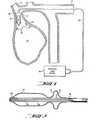
- FIG. 1 is a schematic view of the high-frequency intra-arterial cardiac support system in its mode of employment in support of the left heart.
- Left ventricle 10 is assisted by balloon pump 20 located in ascending aorta 11 between aortic valve 12 and the ostium of innominate artery 13.
- pump 20 comprises pumping balloon 14 and valve 15 downstream from balloon 14, both attached to two-lumen catheter 16 which is brought outside the body through the arterial tree, as via subclavian artery 17 in the Figure.
- Pump 20 as seen more particularly in Figure 2, comprises a shaped hollow tubular body of thin elastomeric material cemented to two-lumen catheter 16 to form pumping balloon 14 and valve 15.
- the end of catheter 16 is closed, and the end of balloon 14 is supported, by closure 23, which may advantageously be made of radio-opaque material to facilitate placement of the device.
- the interior of pumping balloon 14 is connected fluidically to one lumen of catheter 16 by holes 22, and the interior of valve 15 is connected fluidically to the other lumen by hole 21.
- dimensions such as thicknesses have been exaggerated in the interest of clarity.
- valve 15 when erected by inflation, should be just sufficient to substantially occlude ascending aorta 11, and the outside diameter of pumping balloon 14 should be somewhat less.
- the inside diameter of the ascending aorta is of the order of of 2.5 centimeters, and the available length for the balloon pump, between the aortic valve and the ostium of the innominate artery, is of the order of 5.0 centimeters.
- two-lumen catheter 16 is connected to control and drive mechanism 18 which cyclically and individually inflates and deflates balloon 14 and erects and collapses valve 15 by fluid flow through lumens of catheter 16.
- control and drive mechanism 18 which cyclically and individually inflates and deflates balloon 14 and erects and collapses valve 15 by fluid flow through lumens of catheter 16.
- the elements of such mechanisms are well known in the art, but the operating parameters of the mechanism of this invention are quite unusual. In particular, the frequencies of inflation and deflation are much higher, and the inflation and deflation volumes are much lower, than those of prior art devices, as will be set forth in greater detail hereinbelow.
- FIG 3 is a schematic view of the high-frequency intra-arterial cardiac support system of this invention in its mode of employment in support of the right heart.
- right ventricle 25 is assisted by balloon pump 20 located in pulmonary trunk 26 just downstream from pulmonary valve 27.
- the catheter be placed in the venous system, leading out through right ventricle 25 and superior vena cava 28 and a brachiocephalic vein 29.
- valve 15 is again located downstream from pumping balloon 14, but that the different direction of approach of the catheter requires that the valve now be placed at the far end of the assembly.
- This arrangement is shown in detail in Figure 4, where similar numbers refer to similar elements in the arrangement shown in Figure 2.
- FIG. 5 is a timing diagram illustrating the sequence of inflations and deflations of the pumping balloon and the valve of the preferred embodiment of the balloon pump of this invention.
- Two modes of operation are shown, called respectively “continuous” and “burst”.
- the letter “B” refers to the pumping balloon and the letter “V” refers to the valve.
- Upward displacement of a trace signifies increased pressure, or inflation, and downward displacement signifies decreased pressure, or deflation.
- the waveforms shown are illustrative only of timing relationships, and that actual balloon and valve pressure and flow waveforms will be quite rounded, approaching the sinusoidal for high frequencies of inflation and deflation.
- the pumping frequency of the balloon pump must be correspondingly increased. Defining the systolic duty cycle as being the fraction of the total heartbeat period occupied by the systolic period leads to a rule of thumb for the burst mode: that the pumping frequency of the balloon pump must be at least three times the beating frequency of the heart divided by the systolic duty cycle.
- pump throughput is essentially proportional to the product of pump displacement and pumping frequency, it follows that higher pumping frequencies permit smaller pumps. At lower pumping frequencies, pump throughput is limited largely by fluid inertia and viscosity forces in the catheter, and is only weakly dependent on pump displacement up to frequencies at which blood inertia effects become dominant: this leads to a preference for the highest practical pumping frequency. Analysis indicates that a pumping frequency of 1000 strokes per minute is attainable, or almost 14 times the nominal adult heart rate, using helium gas as the drive fluid. It is further likely that arterial compliance effects may be less pronounced at such higher frequencies. For one example, a small pumping balloon of only 7.5 ml displacement, at a pumping frequency of 12 per second and a displacement efficiency of 75% may yield a generous 4 liters per minute.
- FIG. 6 It is not absolutely necessary to use an externally-driven valve in order to accomplish pumping. Indeed, some pumping action can be observed if the valve be simply erected by inflation to some moderate constant pressure, especially if a liquid be used as the inflating fluid.
- a preferable arrangement is to use a one-way passive check valve, several of which have been suggested in the literature.
- the structure is mounted upon and cemented to two-lumen catheter 16, and the ribs are fluidically connected to one of the lumens by holes 24, so that they can be erected and collapsed by fluid, preferably a liquid, supplied from the outside through a lumen in the catheter.
- fluid preferably a liquid
Abstract
Description
- This invention relates generally to temporary cardiac assist devices used to assist the operation of a failing, traumatized or infarcted heart for a limited period until either the heart recovers or more definitive treatment can be provided. In particular, it relates to so-called intra-aortic balloon pumps. Such a pump does not require major thoracic surgery to connect it to the circulation but is a collapsible structure which may be introduced into an easily accessible large artery, such as a femoral, and may then be guided into some portion of the aorta, usually the thoracic aorta, where it can be employed to assist the left side of the heart, the side most frequently in need of assistance and the driving force behind the systemic circulation. In the usual "counterpulsation" mode of employment, the balloon is pneumatically inflated during diastole to increase blood pressure and deflated during systole to lower the pressure load upon the ventricle. This device and its mode of operation was described in a paper by Moulopolous, Topaz and Kolff, "Diastolic Balloon Pumping in the Aorta - A Mechanical Assistance to the Failing Circulation", American Heart Journal (1962) 63, p.669.
- Since intra-aortic balloon pumps can be applied with relatively minor surgery and fairly standard vascular catheterization procedures, and afford some useful assistance to the left heart, they are well regarded. However, they provide much less pumping assistance than one would desire, for at least three reasons: first, the conveniently available volume within the aorta is not large compared to the desired stroke volume of the heart; second, the necessity to avoid occlusion of important arteries such as the carotids and renals, and erosion of atherosclerotic plaques, further limits the size of a pump balloon; and third, the elastic compliance of the aortic walls makes the effective pumping displacement of the balloon less than its geometric displacement. Many inventions have been addressed to the alleviation of this problem: For example, U.S. Patent No. 3,504,662 to R.T. Jones shows how to attain better pump fluid dynamics, and U.S. Patent No. 3,692,018 to Goetz and Goetz shows how to direct the limited available flow predominantly to the critical brain and heart circulations. Still, there is no complete solution to the problem of adequate pump output. Also, since the counterpulsation mode requires synchronization with the natural heart, there is a further problem when the available ECG signal is weak, uneven or missing, as may occur in ill patients.
- It is therefore the principal object of this invention to provide an intra-arterial cardiac support system which can fully support the left heart by pumping the entire stroke volume of the heart while maintaining a low systolic intraventricular pressure. It is a further object of this invention to provide such full support with a balloon pump structure which is physically small, as required for easy insertion and safe operation. Further objects of this invention are to provide means for similar support to the right heart and to provide means for supporting circulation even when the heart is atonic or fibrillating.
- According to this invention, the desired objects are attained by positioning a small balloon pump, provided with valve means on its downstream side, in a major artery immediately adjacent to the heart, such as in the ascending aorta between the aortic valve and the ostium of the innominate artery, or in the pulmonary trunk. This small balloon pump iscyclically inflated and deflated at a frequency much higher than that of the beating of the heart, whereby the ejected stroke volume of the ventricle is pumped away by several rapid cycles of balloon pumping. other objects of this invention, as well as the means for attaining them, are set forth in the accompanying Specification and Drawings, wherein:
-
- FIG. 1 is a schematic view of the high-frequency intra-arterial cardiac support system in its mode of employment in support of the left heart.
- FIG. 2 is a cross-section view of a preferred embodiment of the balloon pump of this invention as used in the mode of employment illustrated in Figure 1.
- FIG. 3 is a schematic view of the high-frequency intra-arterial cardiac support system in its mode of employment in support of the right heart.
- FIG. 4 is a cross-section view of a preferred embodiment of the balloon pump of this invention as used in the mode of employment illustrated in Figure 3.
- FIG. 5 is a timing diagram illustrating the sequences of inflation and deflation of the parts of the preferred embodiment of the balloon pump.
- PIG. 6 is a perspective view of an alternative form of the valve part of the balloon pump.
- FIG. 7 is a aagittal cross-section of the valve shown in Figure 6, in the plane indicated by 7--7 in that Figure.
- FIG. 8 is a normal cross-section of the valve shown in Figure 6, in the plane indicated by 8--8 in that Figure.
- Reference is made to Figure 1, which is a schematic view of the high-frequency intra-arterial cardiac support system in its mode of employment in support of the left heart.
Left ventricle 10 is assisted byballoon pump 20 located in ascending aorta 11 betweenaortic valve 12 and the ostium ofinnominate artery 13.pump 20 comprisespumping balloon 14 andvalve 15 downstream fromballoon 14, both attached to two-lumen catheter 16 which is brought outside the body through the arterial tree, as viasubclavian artery 17 in the Figure. -
Pump 20, as seen more particularly in Figure 2, comprises a shaped hollow tubular body of thin elastomeric material cemented to two-lumen catheter 16 to formpumping balloon 14 andvalve 15. The end ofcatheter 16 is closed, and the end ofballoon 14 is supported, byclosure 23, which may advantageously be made of radio-opaque material to facilitate placement of the device. The interior ofpumping balloon 14 is connected fluidically to one lumen ofcatheter 16 byholes 22, and the interior ofvalve 15 is connected fluidically to the other lumen byhole 21. In the ,Drawings, dimensions such as thicknesses have been exaggerated in the interest of clarity. - Referring again to Figure 1, it is seen that the outside diameter of
valve 15, when erected by inflation, should be just sufficient to substantially occlude ascending aorta 11, and the outside diameter of pumpingballoon 14 should be somewhat less. Clearly, a number of sizes will be needed to fit the population of potential patients. In most adults, the inside diameter of the ascending aorta is of the order of of 2.5 centimeters, and the available length for the balloon pump, between the aortic valve and the ostium of the innominate artery, is of the order of 5.0 centimeters. - It can also be seen that two-
lumen catheter 16 is connected to control anddrive mechanism 18 which cyclically and individually inflates and deflatesballoon 14 and erects and collapsesvalve 15 by fluid flow through lumens ofcatheter 16. The elements of such mechanisms are well known in the art, but the operating parameters of the mechanism of this invention are quite unusual. In particular, the frequencies of inflation and deflation are much higher, and the inflation and deflation volumes are much lower, than those of prior art devices, as will be set forth in greater detail hereinbelow. - Reference is now made to Figure 3, which is a schematic view of the high-frequency intra-arterial cardiac support system of this invention in its mode of employment in support of the right heart. Here,
right ventricle 25 is assisted byballoon pump 20 located inpulmonary trunk 26 just downstream frompulmonary valve 27. In this application, it is preferable that the catheter be placed in the venous system, leading out throughright ventricle 25 andsuperior vena cava 28 and abrachiocephalic vein 29. It will be noted thatvalve 15 is again located downstream from pumpingballoon 14, but that the different direction of approach of the catheter requires that the valve now be placed at the far end of the assembly. This arrangement is shown in detail in Figure 4, where similar numbers refer to similar elements in the arrangement shown in Figure 2. - Reference is now made to Figure 5, which is a timing diagram illustrating the sequence of inflations and deflations of the pumping balloon and the valve of the preferred embodiment of the balloon pump of this invention. Two modes of operation are shown, called respectively "continuous" and "burst". In each case, the letter "B" refers to the pumping balloon and the letter "V" refers to the valve. Upward displacement of a trace signifies increased pressure, or inflation, and downward displacement signifies decreased pressure, or deflation. It will be recognized that the waveforms shown are illustrative only of timing relationships, and that actual balloon and valve pressure and flow waveforms will be quite rounded, approaching the sinusoidal for high frequencies of inflation and deflation.
- Examination of the solid-line "continuous mode" traces of Figure 5, in the context of the arrangements shown in Figures 1 and 3, shows that in each case the phasing of the motions of the pumping balloon and the valve, in the presence of the natural valves of the heart, is such as to cause peristaltic pumping of the blood away from the natural valves, and in the direction of natural flow. Considerations of desired pumping throughput and available space for the balloon pump indicate that the balloon pump should make at least three pumping cycles for each beat of the heart, and preferably more, in order to permit a smaller and more easily inserted and positioned balloon pump. This leads to the rule of thumb that the pumping frequency of the balloon pump must be at least three times the beating frequency of the heart.
- If it is desired to unload the natural ventricle completely, one may employ the "burst mode" illustrated in Figure 5, in which all the pumping cycles of the balloon pump are accomplished during the period of natural systole. Clearly, in order to provide at least three pumping cycles of the balloon pump within this shortened period, the pumping frequency of the balloon pump must be correspondingly increased. Defining the systolic duty cycle as being the fraction of the total heartbeat period occupied by the systolic period leads to a rule of thumb for the burst mode: that the pumping frequency of the balloon pump must be at least three times the beating frequency of the heart divided by the systolic duty cycle.
- If it is desired to increase perfusion of the coronary arteries in a system used to assist the left heart, one may make a slight modification of the control waveforms as indicated by the dashed lines labelled "C" in Figure 5. It can be seen that the effect is to omit a deflation of the valve and momentarily to i impede outflow from the pump during inflation of the pumping balloon, and application of a pulse of blood pressure to ostia of the coronary arteries, such as the one shown at 19 in Figure 1. One or more of these events may be used advantageously at the beginning of diastole, as shown for burst mode, or occasionally during continuous mode.
- Since pump throughput is essentially proportional to the product of pump displacement and pumping frequency, it follows that higher pumping frequencies permit smaller pumps. At lower pumping frequencies, pump throughput is limited largely by fluid inertia and viscosity forces in the catheter, and is only weakly dependent on pump displacement up to frequencies at which blood inertia effects become dominant: this leads to a preference for the highest practical pumping frequency. Analysis indicates that a pumping frequency of 1000 strokes per minute is attainable, or almost 14 times the nominal adult heart rate, using helium gas as the drive fluid. It is further likely that arterial compliance effects may be less pronounced at such higher frequencies. For one example, a small pumping balloon of only 7.5 ml displacement, at a pumping frequency of 12 per second and a displacement efficiency of 75% may yield a generous 4 liters per minute.
- At higher pumping frequencies, the precise phase relationship between the individual pumping cycles and the cardiac cycle is quite immaterial. Therefore, in the continuous mode, synchronization with the EKG is unnecessary. For this reason, when used bilaterally, this system can support circulation even when the heart is atonic or fibrillating.
- It is not absolutely necessary to use an externally-driven valve in order to accomplish pumping. Indeed, some pumping action can be observed if the valve be simply erected by inflation to some moderate constant pressure, especially if a liquid be used as the inflating fluid. A preferable arrangement is to use a one-way passive check valve, several of which have been suggested in the literature. For this purpose, I prefer the structure shown in Figures 6, 7 and 8 which are, respectively, a perspective view and sagittal and normal cross-sections of my preferred passive valve. As shown in the Figures, it is an umbrella-like structure comprising
inflatable ribs 31 supporting aflexible canopy 30, both made of thin elastomeric material. The structure is mounted upon and cemented to two-lumen catheter 16, and the ribs are fluidically connected to one of the lumens byholes 24, so that they can be erected and collapsed by fluid, preferably a liquid, supplied from the outside through a lumen in the catheter. - Given the foregoing teaching, those skilled in the art to which this invention pertains may readily devise further or extended embodiments. For example, in cases where one or more of the valves of the natural heart are damaged or otherwise incompetent, one may provide the balloon pump with an additional valve at the upstream end, either an externally-driven valve as shown in Figures 1 and 3, driven through an additional catheter lumen, or a passive valve as shown in Figures 6, 7 and 8. Various other features and advantages not specifically enumerated will occur to those versed in the art, as likewise many variations of the embodiments which have been illustrated, all of which may be achieved without departing from the spirit and scope of the invention as defined by the following claims:
Claims (11)
Applications Claiming Priority (2)
| Application Number | Priority Date | Filing Date | Title |
|---|---|---|---|
| US75510785A | 1985-07-15 | 1985-07-15 | |
| US755107 | 1985-07-15 |
Publications (2)
| Publication Number | Publication Date |
|---|---|
| EP0209070A2 true EP0209070A2 (en) | 1987-01-21 |
| EP0209070A3 EP0209070A3 (en) | 1988-07-20 |
Family
ID=25037757
Family Applications (1)
| Application Number | Title | Priority Date | Filing Date |
|---|---|---|---|
| EP19860109358 Withdrawn EP0209070A3 (en) | 1985-07-15 | 1986-07-09 | High frequency intra-arterial cardiac support system |
Country Status (3)
| Country | Link |
|---|---|
| EP (1) | EP0209070A3 (en) |
| JP (1) | JPS6284770A (en) |
| IL (1) | IL79405A0 (en) |
Cited By (7)
| Publication number | Priority date | Publication date | Assignee | Title |
|---|---|---|---|---|
| US4902272A (en) * | 1987-06-17 | 1990-02-20 | Abiomed Cardiovascular, Inc. | Intra-arterial cardiac support system |
| US4906229A (en) * | 1988-05-03 | 1990-03-06 | Nimbus Medical, Inc. | High-frequency transvalvular axisymmetric blood pump |
| FR2681789A1 (en) * | 1991-09-30 | 1993-04-02 | Nippon Zeon Co | Apparatus for circulatory assistance |
| US5372573A (en) * | 1989-06-20 | 1994-12-13 | British Technology Group Limited | Blood flow |
| WO1999015227A1 (en) * | 1997-09-26 | 1999-04-01 | Cardeon Corporation | Main stage catheterization instrument |
| US6669674B1 (en) | 1997-09-26 | 2003-12-30 | Cardeon Corporation | Introducer and perfusion cannula |
| US11426563B2 (en) | 2018-12-03 | 2022-08-30 | Nxt Biomedical, Llc | Blood pump or balloon cycling and venous occlusion |
Families Citing this family (2)
| Publication number | Priority date | Publication date | Assignee | Title |
|---|---|---|---|---|
| CA1325937C (en) * | 1987-05-29 | 1994-01-11 | Ingemar H. Lundquist | Retroperfusion and retroinfusion control apparatus, system and method |
| US11351355B2 (en) * | 2017-10-19 | 2022-06-07 | Datascope Corporation | Devices for pumping blood, related systems, and related methods |
Citations (4)
| Publication number | Priority date | Publication date | Assignee | Title |
|---|---|---|---|---|
| US3266487A (en) * | 1963-06-04 | 1966-08-16 | Sundstrand Corp | Heart pump augmentation system and apparatus |
| US3692018A (en) * | 1970-02-11 | 1972-09-19 | Robert H Goetz | Cardiac assistance device |
| US3939820A (en) * | 1974-10-29 | 1976-02-24 | Datascope Corporation | Single-chamber, multi-section balloon for cardiac assistance |
| US4522195A (en) * | 1981-05-25 | 1985-06-11 | Peter Schiff | Apparatus for left heart assist |
Family Cites Families (2)
| Publication number | Priority date | Publication date | Assignee | Title |
|---|---|---|---|---|
| JPS522231A (en) * | 1975-06-24 | 1977-01-08 | Hitachi Ltd | Information processing apparatus |
| JPS5545220A (en) * | 1978-09-27 | 1980-03-29 | Hitachi Ltd | Trunk circuit |
-
1986
- 1986-07-09 EP EP19860109358 patent/EP0209070A3/en not_active Withdrawn
- 1986-07-14 IL IL79405A patent/IL79405A0/en unknown
- 1986-07-15 JP JP61166562A patent/JPS6284770A/en active Pending
Patent Citations (4)
| Publication number | Priority date | Publication date | Assignee | Title |
|---|---|---|---|---|
| US3266487A (en) * | 1963-06-04 | 1966-08-16 | Sundstrand Corp | Heart pump augmentation system and apparatus |
| US3692018A (en) * | 1970-02-11 | 1972-09-19 | Robert H Goetz | Cardiac assistance device |
| US3939820A (en) * | 1974-10-29 | 1976-02-24 | Datascope Corporation | Single-chamber, multi-section balloon for cardiac assistance |
| US4522195A (en) * | 1981-05-25 | 1985-06-11 | Peter Schiff | Apparatus for left heart assist |
Non-Patent Citations (1)
| Title |
|---|
| American Heart Journal, Vol. 63, No. 5 May 1962 S.D. MOULOPOULOS et al. "Diastolic Balloon Pumping in the Aorta-A Mechanical Assistance to the Failing Circulation" pages 669-675 *pages 669, 670 * * |
Cited By (9)
| Publication number | Priority date | Publication date | Assignee | Title |
|---|---|---|---|---|
| US4902272A (en) * | 1987-06-17 | 1990-02-20 | Abiomed Cardiovascular, Inc. | Intra-arterial cardiac support system |
| US4906229A (en) * | 1988-05-03 | 1990-03-06 | Nimbus Medical, Inc. | High-frequency transvalvular axisymmetric blood pump |
| EP0415949A1 (en) * | 1988-05-03 | 1991-03-13 | Nimbus Medical Inc | High-frequency transvalvular axisymmetric blood pump. |
| EP0415949A4 (en) * | 1988-05-03 | 1991-07-03 | Nimbus Medical, Inc. | High-frequency transvalvular axisymmetric blood pump |
| US5372573A (en) * | 1989-06-20 | 1994-12-13 | British Technology Group Limited | Blood flow |
| FR2681789A1 (en) * | 1991-09-30 | 1993-04-02 | Nippon Zeon Co | Apparatus for circulatory assistance |
| WO1999015227A1 (en) * | 1997-09-26 | 1999-04-01 | Cardeon Corporation | Main stage catheterization instrument |
| US6669674B1 (en) | 1997-09-26 | 2003-12-30 | Cardeon Corporation | Introducer and perfusion cannula |
| US11426563B2 (en) | 2018-12-03 | 2022-08-30 | Nxt Biomedical, Llc | Blood pump or balloon cycling and venous occlusion |
Also Published As
| Publication number | Publication date |
|---|---|
| EP0209070A3 (en) | 1988-07-20 |
| JPS6284770A (en) | 1987-04-18 |
| IL79405A0 (en) | 1986-10-31 |
Similar Documents
| Publication | Publication Date | Title |
|---|---|---|
| US4785795A (en) | High-frequency intra-arterial cardiac support system | |
| US4902272A (en) | Intra-arterial cardiac support system | |
| US4080958A (en) | Apparatus for aiding and improving the blood flow in patients | |
| US6468200B1 (en) | Segmented peristaltic intra-aortic balloon pump | |
| US3504662A (en) | Intra-arterial blood pump | |
| US4014317A (en) | Multipurpose cardiocirculatory assist cannula and methods of use thereof | |
| US7229402B2 (en) | Minimally invasive ventricular assist technology and method | |
| US4546759A (en) | Method and apparatus for assisting human heart function | |
| US4861330A (en) | Cardiac assist device and method | |
| US5928132A (en) | Closed chest intra-aortic balloon based ventricular assist device | |
| US5688245A (en) | Cannula system for a biventricular cardiac support system or a cardiopulmonary bypass system | |
| US4527549A (en) | Method of and means for intraaortic assist | |
| EP0471029B1 (en) | Heart-assist balloon pump | |
| US6190304B1 (en) | Enhanced intra-aortic balloon assist device | |
| US4648384A (en) | Retrograde coronary sinus perfusion device and method | |
| US5820542A (en) | Modified circulatory assist device | |
| EP0415949B1 (en) | High-frequency transvalvular axisymmetric blood pump | |
| US8221303B2 (en) | Intra-ventricular cardiac assist device and related method of use | |
| US8784292B2 (en) | Double balloon pump cardiac assist device and related method of use | |
| JPH06510686A (en) | Cardiac support device that can be implanted subcutaneously | |
| US6149578A (en) | Piston-action intra-aortic coronary assist device | |
| US20080207986A1 (en) | Heart assist device | |
| WO1999059653A1 (en) | Coronary artery counterpulsation device and method | |
| EP0209070A2 (en) | High frequency intra-arterial cardiac support system | |
| US11253691B2 (en) | Intra-aortic dual balloon driving pump catheter device |
Legal Events
| Date | Code | Title | Description |
|---|---|---|---|
| PUAI | Public reference made under article 153(3) epc to a published international application that has entered the european phase |
Free format text: ORIGINAL CODE: 0009012 |
|
| AK | Designated contracting states |
Kind code of ref document: A2 Designated state(s): BE CH DE FR GB IT LI LU NL SE |
|
| PUAL | Search report despatched |
Free format text: ORIGINAL CODE: 0009013 |
|
| AK | Designated contracting states |
Kind code of ref document: A3 Designated state(s): BE CH DE FR GB IT LI LU NL SE |
|
| 17P | Request for examination filed |
Effective date: 19890112 |
|
| RAP1 | Party data changed (applicant data changed or rights of an application transferred) |
Owner name: ABIOMED LIMITED PARTNERSHIP |
|
| 17Q | First examination report despatched |
Effective date: 19900711 |
|
| RAP1 | Party data changed (applicant data changed or rights of an application transferred) |
Owner name: ABIOMED, INC. |
|
| RAP1 | Party data changed (applicant data changed or rights of an application transferred) |
Owner name: ABIOMED, INC. ( A DELAWARE CORPORATION) |
|
| STAA | Information on the status of an ep patent application or granted ep patent |
Free format text: STATUS: THE APPLICATION IS DEEMED TO BE WITHDRAWN |
|
| 18D | Application deemed to be withdrawn |
Effective date: 19920211 |
|
| RIN1 | Information on inventor provided before grant (corrected) |
Inventor name: SINGH, PARAM I. |