EP0213689A2 - Plasma torch shutdown circuit - Google Patents
Plasma torch shutdown circuit Download PDFInfo
- Publication number
- EP0213689A2 EP0213689A2 EP86303754A EP86303754A EP0213689A2 EP 0213689 A2 EP0213689 A2 EP 0213689A2 EP 86303754 A EP86303754 A EP 86303754A EP 86303754 A EP86303754 A EP 86303754A EP 0213689 A2 EP0213689 A2 EP 0213689A2
- Authority
- EP
- European Patent Office
- Prior art keywords
- power supply
- circuit
- signal
- torch
- voltage
- Prior art date
- Legal status (The legal status is an assumption and is not a legal conclusion. Google has not performed a legal analysis and makes no representation as to the accuracy of the status listed.)
- Withdrawn
Links
Images
Classifications
-
- H—ELECTRICITY
- H05—ELECTRIC TECHNIQUES NOT OTHERWISE PROVIDED FOR
- H05H—PLASMA TECHNIQUE; PRODUCTION OF ACCELERATED ELECTRICALLY-CHARGED PARTICLES OR OF NEUTRONS; PRODUCTION OR ACCELERATION OF NEUTRAL MOLECULAR OR ATOMIC BEAMS
- H05H1/00—Generating plasma; Handling plasma
- H05H1/24—Generating plasma
- H05H1/26—Plasma torches
- H05H1/32—Plasma torches using an arc
- H05H1/34—Details, e.g. electrodes, nozzles
- H05H1/36—Circuit arrangements
Definitions
- This invention relates to a plasma torch shutdown circuit as set forth in the introductory part of claim 1.
- Plasma torches also known as electric arc torches, are commonly used for cutting, welding and spray bonding of workpieces and operate by directing a plasma consisting of ionized gas particles toward a workpiece.
- Typical plasma torches are illustrated in US Patents 4,324,971, 4,170,727 and 3,813,510, assigned to our.
- a gas to be ionized is supplied to the front end of the torch in front of an electrode.
- a d.c. potential is applied between the electrode and the workpiece by a power supply that usually includes a dropping transformer and bridge rectifier. Gas ionized by this voltage exits an opening of a tip surrounding the electrode and appears as a flame which extends externally from the tip.
- the arc jumps from the electrode to the workpiece and applies heat sufficient to cut, weld or bond the workpiece, as desired.
- the torch can operate either in a stand-off mode or in a drag mode.
- the torch tip In the stand-off mode, the torch tip is maintained a short distance above the workpiece; say 6 mm.
- an arc is undesirably formed within the torch itself between the electrode and the surrounding tip and then from the tip to the workpiece. This condition is called double arcing.
- an arc is undesirably formed within the torch itself between the electrode and the tip or any other metallic part of the internal torch body which is electrically connected to the tip. The electricity completes its path by flowing from the tip to the workpiece because the tip is touching the workpiece. The existence of the internal arc is usually not readily apparent to the torch user. If permitted to continue for a time, internal damage to the torch occurs.
- One technique suggested for dealing with this problem is to sense an increased voltage of the torch tip resulting from the internal arcing, and turn off the power supply in response to an increase of that voltage over some threshold. This technique is satisfactory for detecting internal arcing during the stand-off mode, but is rendered inoperative during the drag mode because there is no voltage to detect on the top when the tip is in electrical contact with the workpiece which is grounded.
- the present invention is defined in the characterising part of claim 1.
- the undesired internal arcing of the plasma torch causes the voltage level between the internal torch electrode and the workpiece to drop to a fraction of its normal operating voltage.
- the undesired arcing is thus detected by this voltage drop and the power supply disconnected.
- these safety circuits are disabled for a short time after such initial turn-on in order to allow the operating voltage of the system to rise to its normal level before the automatic power shut-off feature is enabled.
- a plasma torch head 11 of a standard design is schematically illustrated adjacent a workpiece 13 upon which the torch is operating.
- a case 15 of the torch has a tip element 17 attached at one end.
- An electrode 19 is held within the case 15 and tip 17.
- the tip 17 has an opening 21 at one end.
- a source 23 of plasma gas under pressure is connected with the interior of the torch 11 by a conduit 25. The plasma gas flows through the conduit 25, around the electrode 19 and then out of the opening 21.
- Conductors 27 and 29 carry the direct current power supply to the torch head and workpiece.
- the negative voltage lead 27 is attached to the electrode 19, and the ground potential lead 29 is connected to the workpiece 13.
- an arc is formed between an end of the electrode 19 adjacent the tip opening 21 and the workpiece 13 through the flowing gas, thereby providing the heat for performing the desired cutting or welding operation on the workpiece 13.
- the power supply lines 27 and 29 of the example system of Figure 1 are connected to an output of a bridge rectifier whose input is connected to secondary windings of a drooping transformer 33.
- Primary windings of the transformer 33 are connected through lines 35 and 37 to single pole switches 39 and 41, respectively, and then to the a.c. power line source.
- the ON/OFF switches 39 and 41 are preferably operated together as contacts of a solenoid 43 in response to an electrical signal in a line 45.
- the desired condition of operation is, as is well known, for the arc to extend from the lower end of the electrode 19, through the orifice 21 and against the workpiece 13. It is not unusual, however, for the arc to extend instead between the electrode 19 and an inner surface of the tip 17. If this is permitted to continue very long, the electrode, tip and/or other internal parts are severely burned or melted due to excessive heat generated. This renders the torch unusable until repaired. Heretofore, such a condition has been detected primarily by a visual indication of the torch operator, but by the time it is noticed, excessive damage has already been done.
- the conditions that cause this undesirable internal arcing are many.
- One cause is a reduced flow of plasma gas through the torch and out the opening 21. It is the swirling motion of plasma gas that provides a high resistance path between the electrode and the internal surface of the tip 17. But when the plasma gas source 23 does not provide enough gas, or there is a leak in the system, or the opening 21 is covered by a placement against the workpiece, or some other cause, such internal arcing will occur.
- Another common cause of such internal arcing is the excessive wear of the lower end of the electrode 19 from extended periods of use. As the electrode end burns upward away from the opening 21, the arc finds a lower resistance path to the tip 17 than to the workpiece 13.
- control circuits 51 are provided to turn off the power to the transformer 33 by actuating the solenoid 43 when such conditions are detected. Since the transformer 33 is wound to have a generally constant current output under varying load conditions, it has been found that the undesired internal arcing conditions cause the output voltage across lines 27 and 29 of such a power supply to decrease significantly from that voltage that exists under normal operating conditions without the undesired internal arcing. It is, therefore, this voltage drop that is sensed by the circuits 51 and which causes the power to be turned off at switches 39 and 41. This voltage is sensed by a line 53 connected to the negative rectifier output line 27, and by a connection to ground potential.
- a manually operated switch 55 is Also connected to the control circuits 51, through a line 57, is a manually operated switch 55.
- the pushbutton switch 55 is of a type currently used in plasma torches to cause the power supply to be turned off unless the operator is depressing the switch.
- a plasma gas flow sensor 59 that is connected by a line 61 to the control circuits 51. As in current torches, the power supply is turned off in response to sensing little or no plasma gas flow into the torch.
- a threshold circuit 65 receives the bridge rectifier 31 output voltage as an input and emits as an output, in a line 67, a binary signal representative of whether the rectifier output voltage is above or below a specified threshold.
- a typical torch operating voltage is around 100 volts, and the threshold is set to be about 50 volts, or one-half of the normal operating voltage.
- the voltage in the line 67 is denoted to have a value of a logical "1" when the rectifier output voltage is above the set threshold, and a level of a logical "0" when below that threshold.
- the circuit 65 may be formed of any commonly available threshold device, such as a comparator circuit, inherent threshold operation of available logic elements, and the like.
- Additional logic circuit elements of Figure 2 include an OR-gate 69 having the line 67 as one of two inputs, the other input being a line 71.
- An output line 73 becomes one input of an AND-gate 75 whose output is a line 77.
- the AND-gate 75 has a second input, a line 79.
- the line 79 is an output of an AND-gate 83 which is shown to have four inputs, namely the line 57 from the operator controlled ON/OFF switch 55, the line 61 from the plasma gas flow sensor 59, and two other lines 85 that are often provided for detecting other conditions, such as excessive power supply temperature, open cabinet doors, and the like.
- a normal condition from any of these sensors in the four input lines to the AND gate 83 is considered to be a logical "1" voltage level.
- its output line 79 is a "1" which causes the driver circuit 81 to keep the power ON/OFF switch in its ON position.
- This initial turn-on condition is detected when the operator pushes the power control button 55 ( Figure 1) which causes the output of the AND-gate 83 ( Figure 2) in line 79 to rise from a logical "0" to a "1".
- the circuit 87 in response to that change of voltage level in the line 79, generates a logical "1" in the voltage level in the line 71 to effectively disable the threshold circuit 65. This occurs since, during that short interval of time after power is first turned on to the system, the logical "1" in line 71 is forced through the line 73 to the AND-gate 75 regardless of whether the voltage level in the line 67 is a "0" or "1".
- the reason for this timing circuit 87 is to force the control circuits to allow power to remain connected for a short time until the voltage level which is sensed by the threshold circuit 65 rises from zero to its normal operating voltage. If it does so rise during that interval, the return of the voltage level in the line 71 from a "1" to a "0" at the end of that short interval does not affect operation of the device. However, if there is a problem with internal arcing at the time that power is turned on to the system, it may turn off again at the end of that initial interval set by the timing circuit 87 since the voltage in the line 67 will be "0" instead of "1". But such a short period of arcing causes little damage.
- the timing circuit 87 can be of any convenient design that utilizes a resistance-capacitance (RC) circuit, as is well known.
- the output of the threshold detecting circuit 65 (which is shown in Figure 3(B)) changes from a "0" to a "1" sometime later, at time t1, the time necessary for the power supply output to reach its normal level after first being turned on.
- the signal in the line 71 keeps the control circuits from immediately shutting off the power supply again, at least until the time t2 when the signal output of the timing circuit 87 returns to its "0" level, as shown in Figure 3(A).
- the interval between times t0 and t2 is usually a fraction of a second, as little as 0.1 second.
- FIG. 3 Another change of condition is illustrated in Figure 3, occurring at time t3. It is assumed that the threshold circuit 65, at that instant, detects a low voltage, and its output thus drops from a "1" to a "0", as shown in Figure 3(B). This then causes the signal in line 77, as shown in Figure 3(D), to drop from a "1” to a "0", and the driving circuits 81 are caused to turn off the power supply through the solenoid switch.
Abstract
Description
- This invention relates to a plasma torch shutdown circuit as set forth in the introductory part of
claim 1. - Plasma torches, also known as electric arc torches, are commonly used for cutting, welding and spray bonding of workpieces and operate by directing a plasma consisting of ionized gas particles toward a workpiece. Typical plasma torches are illustrated in US Patents 4,324,971, 4,170,727 and 3,813,510, assigned to ourselves. A gas to be ionized is supplied to the front end of the torch in front of an electrode. A d.c. potential is applied between the electrode and the workpiece by a power supply that usually includes a dropping transformer and bridge rectifier. Gas ionized by this voltage exits an opening of a tip surrounding the electrode and appears as a flame which extends externally from the tip. As the torch head or front end is brought down towards the workpiece, the arc jumps from the electrode to the workpiece and applies heat sufficient to cut, weld or bond the workpiece, as desired.
- The torch can operate either in a stand-off mode or in a drag mode. In the stand-off mode, the torch tip is maintained a short distance above the workpiece; say 6 mm. In the drag mode, the torch tip is touching the work, thus being in electrical contact with the work, and the torch is dragged across the workpiece.
- Occasionally, during the use of such a torch in the stand-off mode, an arc is undesirably formed within the torch itself between the electrode and the surrounding tip and then from the tip to the workpiece. This condition is called double arcing. Occasionally, during the use of such a torch in the drag mode, an arc is undesirably formed within the torch itself between the electrode and the tip or any other metallic part of the internal torch body which is electrically connected to the tip. The electricity completes its path by flowing from the tip to the workpiece because the tip is touching the workpiece. The existence of the internal arc is usually not readily apparent to the torch user. If permitted to continue for a time, internal damage to the torch occurs.
- One technique suggested for dealing with this problem is to sense an increased voltage of the torch tip resulting from the internal arcing, and turn off the power supply in response to an increase of that voltage over some threshold. This technique is satisfactory for detecting internal arcing during the stand-off mode, but is rendered inoperative during the drag mode because there is no voltage to detect on the top when the tip is in electrical contact with the workpiece which is grounded.
- Therefore, it is a principal object of the present invention to provide a power supply control technique and system that turns off the power to a torch in response to undesired internal arcing no matter how the torch is being used at the time.
- The present invention is defined in the characterising part of
claim 1. The undesired internal arcing of the plasma torch causes the voltage level between the internal torch electrode and the workpiece to drop to a fraction of its normal operating voltage. The undesired arcing is thus detected by this voltage drop and the power supply disconnected. In order to allow the power supply to be initially turned on, these safety circuits are disabled for a short time after such initial turn-on in order to allow the operating voltage of the system to rise to its normal level before the automatic power shut-off feature is enabled. - The invention will be described in more detail, by way of example, and with reference to the accompanying drawings in which:
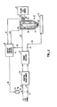
- Figure 1 is a system schematic block diagram of a plasma torch and its power supply that incorporates the improvements of the present invention;
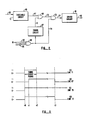
- Figure 2 is a block diagram of the control circuits of the system of Figure 1; and
- Figure 3 illustrates exemplary logic signals in the control circuit of Figure 2.
- Referring to Figure 1, a plasma torch head 11 of a standard design is schematically illustrated adjacent a
workpiece 13 upon which the torch is operating. Acase 15 of the torch has atip element 17 attached at one end. Anelectrode 19 is held within thecase 15 andtip 17. Thetip 17 has an opening 21 at one end. Asource 23 of plasma gas under pressure is connected with the interior of the torch 11 by aconduit 25. The plasma gas flows through theconduit 25, around theelectrode 19 and then out of the opening 21. -
Conductors negative voltage lead 27 is attached to theelectrode 19, and the groundpotential lead 29 is connected to theworkpiece 13. As is well known, an arc is formed between an end of theelectrode 19 adjacent the tip opening 21 and theworkpiece 13 through the flowing gas, thereby providing the heat for performing the desired cutting or welding operation on theworkpiece 13. - As is standard practice, the
power supply lines drooping transformer 33. Primary windings of thetransformer 33 are connected throughlines single pole switches OFF switches solenoid 43 in response to an electrical signal in aline 45. - The desired condition of operation is, as is well known, for the arc to extend from the lower end of the
electrode 19, through theorifice 21 and against theworkpiece 13. It is not unusual, however, for the arc to extend instead between theelectrode 19 and an inner surface of thetip 17. If this is permitted to continue very long, the electrode, tip and/or other internal parts are severely burned or melted due to excessive heat generated. This renders the torch unusable until repaired. Heretofore, such a condition has been detected primarily by a visual indication of the torch operator, but by the time it is noticed, excessive damage has already been done. - The conditions that cause this undesirable internal arcing are many. One cause is a reduced flow of plasma gas through the torch and out the opening 21. It is the swirling motion of plasma gas that provides a high resistance path between the electrode and the internal surface of the
tip 17. But when theplasma gas source 23 does not provide enough gas, or there is a leak in the system, or theopening 21 is covered by a placement against the workpiece, or some other cause, such internal arcing will occur. - Another common cause of such internal arcing is the excessive wear of the lower end of the
electrode 19 from extended periods of use. As the electrode end burns upward away from theopening 21, the arc finds a lower resistance path to thetip 17 than to theworkpiece 13. - Therefore, in accordance with the present invention, in order to automatically sense such undesired internal arcing,
control circuits 51 are provided to turn off the power to thetransformer 33 by actuating thesolenoid 43 when such conditions are detected. Since thetransformer 33 is wound to have a generally constant current output under varying load conditions, it has been found that the undesired internal arcing conditions cause the output voltage acrosslines circuits 51 and which causes the power to be turned off atswitches line 53 connected to the negativerectifier output line 27, and by a connection to ground potential. - Also connected to the
control circuits 51, through aline 57, is a manually operatedswitch 55. Thepushbutton switch 55 is of a type currently used in plasma torches to cause the power supply to be turned off unless the operator is depressing the switch. Also shown in Figure 1 is a plasmagas flow sensor 59 that is connected by aline 61 to thecontrol circuits 51. As in current torches, the power supply is turned off in response to sensing little or no plasma gas flow into the torch. - The
control circuits 51 are shown in a schematic block and logic diagram of Figure 2. Athreshold circuit 65 receives thebridge rectifier 31 output voltage as an input and emits as an output, in aline 67, a binary signal representative of whether the rectifier output voltage is above or below a specified threshold. A typical torch operating voltage is around 100 volts, and the threshold is set to be about 50 volts, or one-half of the normal operating voltage. For the purposes of this explanation, the voltage in theline 67 is denoted to have a value of a logical "1" when the rectifier output voltage is above the set threshold, and a level of a logical "0" when below that threshold. Thecircuit 65 may be formed of any commonly available threshold device, such as a comparator circuit, inherent threshold operation of available logic elements, and the like. - Additional logic circuit elements of Figure 2 include an OR-gate 69 having the
line 67 as one of two inputs, the other input being aline 71. Anoutput line 73 becomes one input of an AND-gate 75 whose output is aline 77. The AND-gate 75 has a second input, aline 79. - In operation, a "1" in the
line 67 will cause a "1" to appear in theline 73 which, in turn, will cause a logical "1" voltage level in theline 77 so long as a logical "1" exists in itssecond input 79 at the same time. When these conditions are met, drivingcircuits 81 are caused to emit a signal in theline 45 to the solenoid 43 (Figure 1) that keeps theswitches line 79 is an output of an AND-gate 83 which is shown to have four inputs, namely theline 57 from the operator controlled ON/OFF switch 55, theline 61 from the plasmagas flow sensor 59, and twoother lines 85 that are often provided for detecting other conditions, such as excessive power supply temperature, open cabinet doors, and the like. For this example, a normal condition from any of these sensors in the four input lines to the ANDgate 83 is considered to be a logical "1" voltage level. When all four lines are at that level, itsoutput line 79 is a "1" which causes thedriver circuit 81 to keep the power ON/OFF switch in its ON position. When any of these inputs becomes a logical "0", such as by the operator releasing theswitch 55 or the plasma gas flow stopping, the output in theline 79 goes to a logical "0", which causes theoutput 77 of the AND-gate 75 to also go to a logical "0" level. This in turn causes thedriver circuits 81 to operate thesolenoid 43 to open theswitches - When the power supply output voltage falls below the set threshold, a logical "0" exists in the
line 67 which will pass on through the OR-gate 69 and AND-gate 75 to cause thedriver circuits 81 to turn off the power unless there is a logical "1" in theline 71 that is a second input to the OR-gate 69. The voltage level in theline 71 is controlled by atiming circuit 87 whose input is obtained from theline 79. The function of thecircuit 87 is to provide a logical "1" in theline 71 for a short time, such as a 0.1 second, after power is initially turned on to the plasma torch system by closing theswitches line 79 to rise from a logical "0" to a "1". Thecircuit 87, in response to that change of voltage level in theline 79, generates a logical "1" in the voltage level in theline 71 to effectively disable thethreshold circuit 65. This occurs since, during that short interval of time after power is first turned on to the system, the logical "1" inline 71 is forced through theline 73 to the AND-gate 75 regardless of whether the voltage level in theline 67 is a "0" or "1". - The reason for this
timing circuit 87 is to force the control circuits to allow power to remain connected for a short time until the voltage level which is sensed by thethreshold circuit 65 rises from zero to its normal operating voltage. If it does so rise during that interval, the return of the voltage level in theline 71 from a "1" to a "0" at the end of that short interval does not affect operation of the device. However, if there is a problem with internal arcing at the time that power is turned on to the system, it may turn off again at the end of that initial interval set by thetiming circuit 87 since the voltage in theline 67 will be "0" instead of "1". But such a short period of arcing causes little damage. Thetiming circuit 87 can be of any convenient design that utilizes a resistance-capacitance (RC) circuit, as is well known. - The waveforms of Figure 3 best illustrate some of the operation of Figure 2 that has been described above. The voltage levels in the four lines identified in Figure 3 are given, either at a logical "0" or "1" level. In this example, it is assumed that power is initiated to the system at time t0. It is at this time that the output in the
line 79 goes from "0" to "1" since all of its inputs are then a logical "1" voltage level. This starts the timingcircuits 87 which causes its output in theline 71 to change from "0" to "1" at time t0, as shown in Figure 3(A). The output of the threshold detecting circuit 65 (which is shown in Figure 3(B)) changes from a "0" to a "1" sometime later, at time t1, the time necessary for the power supply output to reach its normal level after first being turned on. The signal in theline 71 keeps the control circuits from immediately shutting off the power supply again, at least until the time t2 when the signal output of thetiming circuit 87 returns to its "0" level, as shown in Figure 3(A). The interval between times t0 and t2 is usually a fraction of a second, as little as 0.1 second. - Another change of condition is illustrated in Figure 3, occurring at time t3. It is assumed that the
threshold circuit 65, at that instant, detects a low voltage, and its output thus drops from a "1" to a "0", as shown in Figure 3(B). This then causes the signal inline 77, as shown in Figure 3(D), to drop from a "1" to a "0", and the drivingcircuits 81 are caused to turn off the power supply through the solenoid switch. - Another condition, not shown, which will cause the power to be turned off, is for one of the inputs to the AND-gate 83 to go from a "1" to a "0". This will cause its output (Figure 3(C) curve) to go to a "0". When this occurs, the signal level in the
line 77 also goes from a "1" to a "0" and causes the drivingcircuits 81 to turn off the power to the system. - Although the present invention has been described with respect to a preferred embodiment and specific example thereof, it will be understood that the invention is entitled to protection within the full scope of the appended claims.
Claims (4)
Applications Claiming Priority (2)
| Application Number | Priority Date | Filing Date | Title |
|---|---|---|---|
| US77260685A | 1985-09-04 | 1985-09-04 | |
| US772606 | 1996-12-23 |
Publications (2)
| Publication Number | Publication Date |
|---|---|
| EP0213689A2 true EP0213689A2 (en) | 1987-03-11 |
| EP0213689A3 EP0213689A3 (en) | 1988-09-21 |
Family
ID=25095623
Family Applications (1)
| Application Number | Title | Priority Date | Filing Date |
|---|---|---|---|
| EP86303754A Withdrawn EP0213689A3 (en) | 1985-09-04 | 1986-05-16 | Plasma torch shutdown circuit |
Country Status (2)
| Country | Link |
|---|---|
| EP (1) | EP0213689A3 (en) |
| JP (1) | JPS62267080A (en) |
Cited By (7)
| Publication number | Priority date | Publication date | Assignee | Title |
|---|---|---|---|---|
| US5717187A (en) * | 1994-03-25 | 1998-02-10 | Commonwealth Scientific And Industrial Research Organisation | Plasma torch condition monitoring |
| US5756960A (en) * | 1994-03-25 | 1998-05-26 | Commonwealth Scientific And Industrial Research Organization | Detecting non-symmetrical nozzle wear in a plasma arc torch |
| ES2115542A1 (en) * | 1996-07-24 | 1998-06-16 | Iberdrola Sa | Power supply for plasma furnace torches. |
| WO1998056215A1 (en) * | 1997-06-06 | 1998-12-10 | Hypertherm, Inc. | A safety circuit for a blow forward contact start plasma arc torch |
| US7807937B2 (en) * | 2005-01-03 | 2010-10-05 | Illinois Tool Works Inc. | Method and system of conserving plasma torch consumable |
| US20140254054A1 (en) * | 2009-02-17 | 2014-09-11 | Albert Bulliard | Power supply device for plasma processing |
| CN109709427A (en) * | 2018-12-30 | 2019-05-03 | 常州九圣焊割设备有限公司 | Attrition component fault detection method in plasma arc torch |
Families Citing this family (1)
| Publication number | Priority date | Publication date | Assignee | Title |
|---|---|---|---|---|
| JPH0688141B2 (en) * | 1988-03-24 | 1994-11-09 | 株式会社小松製作所 | Double arc prevention cutting method in plasma arc cutting |
Citations (2)
| Publication number | Priority date | Publication date | Assignee | Title |
|---|---|---|---|---|
| FR2151219A5 (en) * | 1971-08-26 | 1973-04-13 | Shapiro Ilya | Plasma beam arc control - prevents voltage surges |
| JPS597480A (en) * | 1982-07-05 | 1984-01-14 | Matsushita Electric Ind Co Ltd | Automatic arc welding machine |
Family Cites Families (2)
| Publication number | Priority date | Publication date | Assignee | Title |
|---|---|---|---|---|
| JPS53108048A (en) * | 1977-03-04 | 1978-09-20 | Hitachi Ltd | Electron beam welding method |
| JPS6043831B2 (en) * | 1980-08-30 | 1985-09-30 | 株式会社三社電機製作所 | Damage prevention device for plasma arc torch |
-
1986
- 1986-05-14 JP JP11043386A patent/JPS62267080A/en active Pending
- 1986-05-16 EP EP86303754A patent/EP0213689A3/en not_active Withdrawn
Patent Citations (2)
| Publication number | Priority date | Publication date | Assignee | Title |
|---|---|---|---|---|
| FR2151219A5 (en) * | 1971-08-26 | 1973-04-13 | Shapiro Ilya | Plasma beam arc control - prevents voltage surges |
| JPS597480A (en) * | 1982-07-05 | 1984-01-14 | Matsushita Electric Ind Co Ltd | Automatic arc welding machine |
Non-Patent Citations (1)
| Title |
|---|
| PATENT ABSTRACTS OF JAPAN, vol. 8, no. 90 (M-292)[1527], 25th April 1984; & JP-A-59 007 480 (MATSUSHITA DENKI SANGYO K.K.) 14-01-1984 * |
Cited By (11)
| Publication number | Priority date | Publication date | Assignee | Title |
|---|---|---|---|---|
| US5717187A (en) * | 1994-03-25 | 1998-02-10 | Commonwealth Scientific And Industrial Research Organisation | Plasma torch condition monitoring |
| US5756960A (en) * | 1994-03-25 | 1998-05-26 | Commonwealth Scientific And Industrial Research Organization | Detecting non-symmetrical nozzle wear in a plasma arc torch |
| ES2115542A1 (en) * | 1996-07-24 | 1998-06-16 | Iberdrola Sa | Power supply for plasma furnace torches. |
| WO1998056215A1 (en) * | 1997-06-06 | 1998-12-10 | Hypertherm, Inc. | A safety circuit for a blow forward contact start plasma arc torch |
| US5900169A (en) * | 1997-06-06 | 1999-05-04 | Hypertherm, Inc. | Safety circuit for a blow forward contact start plasma arc torch |
| US7807937B2 (en) * | 2005-01-03 | 2010-10-05 | Illinois Tool Works Inc. | Method and system of conserving plasma torch consumable |
| US20140254054A1 (en) * | 2009-02-17 | 2014-09-11 | Albert Bulliard | Power supply device for plasma processing |
| US9214801B2 (en) * | 2009-02-17 | 2015-12-15 | Solvix Gmbh | Power supply device for plasma processing |
| US9997903B2 (en) | 2009-02-17 | 2018-06-12 | Solvix Gmbh | Power supply device for plasma processing |
| CN109709427A (en) * | 2018-12-30 | 2019-05-03 | 常州九圣焊割设备有限公司 | Attrition component fault detection method in plasma arc torch |
| CN109709427B (en) * | 2018-12-30 | 2021-09-03 | 常州九圣焊割设备股份有限公司 | Method for detecting faults of consumable parts in plasma arc spray gun |
Also Published As
| Publication number | Publication date |
|---|---|
| JPS62267080A (en) | 1987-11-19 |
| EP0213689A3 (en) | 1988-09-21 |
Similar Documents
| Publication | Publication Date | Title |
|---|---|---|
| CA2225942C (en) | Plasma pilot arc control | |
| AU614449B2 (en) | Plasma arc torch system interlock | |
| EP0573771B1 (en) | Contact status monitor | |
| KR950011708B1 (en) | Method and circuit for protecting plasma nozzle | |
| US6350960B1 (en) | Parts-in-place safety reset circuit and method for contact start plasma-arc torch | |
| US4814577A (en) | Control circuit in plasma arc cutting and welding equipment designed for transferred arc operation | |
| US6094329A (en) | DI protective switching device | |
| KR900007264B1 (en) | Method of control and apparatus for hot-wire welding | |
| JP2961657B2 (en) | Improved arc retreat circuit and method | |
| US5961855A (en) | Low voltage electrical based parts-in-place (PIP) system for contact start torch | |
| US4585921A (en) | Torch operation interlock device | |
| EP0213689A2 (en) | Plasma torch shutdown circuit | |
| US4663515A (en) | Plasma-arc torch interlock with flow sensing | |
| US6670572B2 (en) | Solenoid control and safety circuit system and method | |
| US4663512A (en) | Plasma-arc torch interlock with pressure sensing | |
| JP3458632B2 (en) | Welding voltage detection method and arc welding machine | |
| JP2850397B2 (en) | Plasma arc processing equipment | |
| US4862095A (en) | Wire electrode breakage detection method and apparatus | |
| KR960001529Y1 (en) | Control device for welding | |
| KR960004789B1 (en) | Welding device for preventing an electric shock | |
| KR100382125B1 (en) | Globular Transfer mode Control method and apparatus in the Inverter Welding Process | |
| JPS6159834B2 (en) | ||
| KR890008327Y1 (en) | Electric shock preventive circuit of a.c. arc welding m/c | |
| JP3264741B2 (en) | Filler wire supply TIG welding equipment | |
| KR200308216Y1 (en) | Voltage reducing device |
Legal Events
| Date | Code | Title | Description |
|---|---|---|---|
| PUAI | Public reference made under article 153(3) epc to a published international application that has entered the european phase |
Free format text: ORIGINAL CODE: 0009012 |
|
| AK | Designated contracting states |
Kind code of ref document: A2 Designated state(s): DE FR GB IT |
|
| PUAL | Search report despatched |
Free format text: ORIGINAL CODE: 0009013 |
|
| AK | Designated contracting states |
Kind code of ref document: A3 Designated state(s): DE FR GB IT |
|
| STAA | Information on the status of an ep patent application or granted ep patent |
Free format text: STATUS: THE APPLICATION IS DEEMED TO BE WITHDRAWN |
|
| 18D | Application deemed to be withdrawn |
Effective date: 19890322 |
|
| RIN1 | Information on inventor provided before grant (corrected) |
Inventor name: SPAULDING, RICHARD A. Inventor name: MOLLETT, WAYMAN LEON Inventor name: WILKINS, RAYMOND G. |