EP0213749B1 - Balloon dilatation catheter with advanceable non-removable guide wire - Google Patents
Balloon dilatation catheter with advanceable non-removable guide wire Download PDFInfo
- Publication number
- EP0213749B1 EP0213749B1 EP86305874A EP86305874A EP0213749B1 EP 0213749 B1 EP0213749 B1 EP 0213749B1 EP 86305874 A EP86305874 A EP 86305874A EP 86305874 A EP86305874 A EP 86305874A EP 0213749 B1 EP0213749 B1 EP 0213749B1
- Authority
- EP
- European Patent Office
- Prior art keywords
- balloon
- guide wire
- lumen
- dilatation catheter
- catheter
- Prior art date
- Legal status (The legal status is an assumption and is not a legal conclusion. Google has not performed a legal analysis and makes no representation as to the accuracy of the status listed.)
- Expired - Lifetime
Links
Images
Classifications
-
- A—HUMAN NECESSITIES
- A61—MEDICAL OR VETERINARY SCIENCE; HYGIENE
- A61M—DEVICES FOR INTRODUCING MEDIA INTO, OR ONTO, THE BODY; DEVICES FOR TRANSDUCING BODY MEDIA OR FOR TAKING MEDIA FROM THE BODY; DEVICES FOR PRODUCING OR ENDING SLEEP OR STUPOR
- A61M25/00—Catheters; Hollow probes
- A61M25/10—Balloon catheters
- A61M25/104—Balloon catheters used for angioplasty
-
- A—HUMAN NECESSITIES
- A61—MEDICAL OR VETERINARY SCIENCE; HYGIENE
- A61M—DEVICES FOR INTRODUCING MEDIA INTO, OR ONTO, THE BODY; DEVICES FOR TRANSDUCING BODY MEDIA OR FOR TAKING MEDIA FROM THE BODY; DEVICES FOR PRODUCING OR ENDING SLEEP OR STUPOR
- A61M25/00—Catheters; Hollow probes
- A61M25/01—Introducing, guiding, advancing, emplacing or holding catheters
- A61M25/09—Guide wires
- A61M25/09016—Guide wires with mandrils
- A61M25/09025—Guide wires with mandrils with sliding mandrils
-
- A—HUMAN NECESSITIES
- A61—MEDICAL OR VETERINARY SCIENCE; HYGIENE
- A61B—DIAGNOSIS; SURGERY; IDENTIFICATION
- A61B17/00—Surgical instruments, devices or methods, e.g. tourniquets
- A61B17/22—Implements for squeezing-off ulcers or the like on the inside of inner organs of the body; Implements for scraping-out cavities of body organs, e.g. bones; Calculus removers; Calculus smashing apparatus; Apparatus for removing obstructions in blood vessels, not otherwise provided for
- A61B2017/22001—Angioplasty, e.g. PCTA
-
- A—HUMAN NECESSITIES
- A61—MEDICAL OR VETERINARY SCIENCE; HYGIENE
- A61M—DEVICES FOR INTRODUCING MEDIA INTO, OR ONTO, THE BODY; DEVICES FOR TRANSDUCING BODY MEDIA OR FOR TAKING MEDIA FROM THE BODY; DEVICES FOR PRODUCING OR ENDING SLEEP OR STUPOR
- A61M25/00—Catheters; Hollow probes
- A61M25/10—Balloon catheters
- A61M2025/1043—Balloon catheters with special features or adapted for special applications
- A61M2025/1079—Balloon catheters with special features or adapted for special applications having radio-opaque markers in the region of the balloon
-
- A—HUMAN NECESSITIES
- A61—MEDICAL OR VETERINARY SCIENCE; HYGIENE
- A61M—DEVICES FOR INTRODUCING MEDIA INTO, OR ONTO, THE BODY; DEVICES FOR TRANSDUCING BODY MEDIA OR FOR TAKING MEDIA FROM THE BODY; DEVICES FOR PRODUCING OR ENDING SLEEP OR STUPOR
- A61M25/00—Catheters; Hollow probes
- A61M25/10—Balloon catheters
- A61M2025/1043—Balloon catheters with special features or adapted for special applications
- A61M2025/1093—Balloon catheters with special features or adapted for special applications having particular tip characteristics
Definitions
- This invention relates to a balloon dilatation catheter comprising a flexible tubular member, having first and second lumens extending therethrough, and an inflatable balloon which is carried by the distal portion of the tubular member, the first lumen extending through the balloon and not being in communication with the interior of the balloon, and the second lumen being in communication with the interior of the balloon.
- the size of the collapsed balloon profile in balloon dilatation catheters makes it possible to assess the potential ability of the balloon catheter to cross a lesion or stenosis.
- the smaller the profile of the collapsed balloon the tighter the lesion (or smaller the hole) the dilatation catheter is able to pass through.
- the present invention is characterised in that a guide wire is slidably disposed in and protrudes from the distal end of the first lumen, the distal end of the guide wire having a coil-like tip with a cross-sectional area which is greater than that of the first lumen and prevents removal of the guide wire through the first lumen.
- a balloon dilatation catheter 10 comprises a flexible elongate tubular member 11 having a first elongate flexible tubular element 12 which is provided with a first lumen 13 extending therethrough.
- the distal portion of the tubular element 12 is provided with a portion 12a of reduced diameter with a tapered transition portion 12b which adjoins a portion 12c of a larger diameter extending to the proximal extremity of the first tubular element.
- a second elongate flexible tubular element 16 is also provided which extends over the first elongate tubular element 12 and is disposed coaxially therewith.
- the second elongate tubular element 16 is of a size so that there is provided between the first and second tubular elements 12 and 16 an annular lumen 17 extending the length of the tubular elements 12 and 16.
- a balloon 18 is carried by the distal portion of the tubular element 16 near the distal extremity thereof and has its interior in communication with the lumen 17.
- the balloon 18 is formed integral with the second tubular element 16.
- the first and second tubular elements 12 and 16 can be formed of a suitable flexible thermo-plastic material such as a polyolefin or polyvinylchloride.
- the distal extremity of the second elongate tubular element 16 is shrunk onto the distal extremity of the first tubular element 12 to form a liquid-tight seal between their distal ends.
- the lumen 17 opens into the balloon 18 and can be used for inflating and deflating the balloon.
- it instead of forming the balloon 18 integral with the second elongate tubular element 16, it can be formed as a separate element and bonded to the second tubular element 16 by suitable means such as an adhesive.
- An adapter 21 is secured to the proximal extremity of the tubular member 11.
- the adapter 21 is of a conventional type and is provided with a main or central arm 22 and a side arm 23.
- the main arm 22 is in communication with the lumen 13 of the first tubular element 12 and is adapted to carry a guide wire 26.
- the guide wire 26 can be formed by a suitable material such as stainless steel and is provided with an elongate portion 26a, a necked down tapered portion 26b and a portion 26c at the distal extremity which is of substantially reduced diameter.
- a spring-like coil 28 is secured to the distal extremity of the guide wire 26 and is in the form of a helix.
- the proximal end of the coil 28 is secured to the distal portion of the guide wire 26 by solder 29.
- a semi-spherical tip 31 is provided at the distal extremity of the coil 28 and joins the tip of the wire 26 to the coil.
- the coil 28 is formed of a suitable material, for example platinum.
- the tip 31 is formed of a suitable material such as gold.
- a band 36 which serves as a marker, is provided on the portion 12a of the first tubular element 12 and is disposed substantially equidistant between the extremities of the balloon 18.
- a torquer 41 of a conventional type is secured to the proximal extremity of the guide wire 26 and is adapted to be grasped by hand for rotating the guide wire as hereinafter described.
- the balloon dilatation catheter shown in Figures 1 and 2 of the drawings can have dimensions such as the following:
- the tubular member 11 extending from the adapter 21 to the balloon 18 can have a suitable length ranging from 40 to 50 cm and preferably a dimension of approximately 135 cm.
- the portion 12c of the first or inner tubular element 12 can have an outside diameter ranging from 0.064 to 0.86 mm (0.025 to 0.034 inch), an inside diameter of 0.36 to 0.51 mm (0.014 to 0.020 inch) and preferably 0.69 and 0.41 mm (0.027 and 0.016 inch) respectively.
- the portion 12a can have an outside diameter of 0.41 to 0.56 mm (0.016 to 0.022 inch) and an inside diameter of 0.2 to 0.3 mm (0.008 to 0.012 inch) and preferably dimensions of 0.51 mm (0.020 inch) for the outside diameter and 0.25 mm (0.010 inch) for the inside diameter.
- the second tubular element 16 can have an outside diameter of 0.97 to 1.21 mm (0.038 to 0.048 inch) and an inside diameter of 0.84 to 1.07 mm (0.033 to 0.042 inch) and preferably an outside diameter of 1.14 mm (0.045 inch) and an inside diameter 0.97 mm (0.038 inch).
- the balloon 18, 2 mm in size can have a collapsed profile of 0.76 to 0.97 mm (0.030 to 0.038 inch) and can have a suitable length of, for example, 15 to 35 mm and preferably a length of approximately 25 mm.
- the distal extremity of the catheter 10 in which the distal extremities of the first and second tubular elements 12 and 16 are bonded together can have a suitable dimension ranging from 0.61 to 0.76 mm (0.024 to 0.030 inch) and preferably a dimension of 0.66 mm (0.026 inch). This extremity can have a length ranging from 3 to 10 mm and preferably a length of approximately 5 mm.
- the portion 26a of the guide wire 26 can have a dimension ranging from 0.33 to 0.36 mm (0.013 to 0.014 inch) and if desired can be coated with a suitable material such as PTFE.
- the portion 26c of the guide wire 26 can have a dimension such as 0.18 to 0.2 mm (0.007 to 0.008 inch).
- the coil 28 can have an outside diameter of 0.3 to 0.41 mm (0.012 to 0.016 inch) and preferably of approximately 0.38 mm (0.015 inch).
- the coil 28 can have a length ranging from 15 mm to 50 mm and preferably has a length of approximately 30 mm.
- the radiopaque marker band 36 can have an internal diameter of 0.53 mm (0.021 inch) with a wall thickness of 0.05 mm (0.002 inch) and a width of approximately 1.14 mm (0.045 inch).
- the catheter 10 with the balloon 18 in a collapsed state is introduced into the vessel in a conventional manner.
- the guide wire 26 can be utilized to facilitate the introduction and advancement of the dilatation catheter 10. Its progress can be observed upon a fluoroscope because the coil 28 is relatively opaque to X-rays.
- the guide wire 26 cannot be retracted from the catheter, it is independently manipulable with respect to the balloon dilatation catheter. For example, if desired the distal extremity of the guide wire 26 and, in particular, the coil 28 can be advanced so it is 7.6 to 10 cm (3 to 4 inches) ahead of the catheter. It also can be rotated by use of the torquer 41.
- the amount of travel of the guide wire 26 is determined by the length of the portion 26c of the guide wire.
- the rearmost extremity of the guide wire 26 is determined when the solder 29 reaches the distal extremity of the first flexible tubular element 12.
- this ex- tendability or advanceability of the guide wire in the dilatation catheter can vary from 10 to 20 cm.
- the amount of advancement of the guide wire 26 can also be adjusted within the limits just described by the positioning of the torquer 41 on the guide wire.
- the balloon 18 can be inflated by introducing a radiopaque contract liquid through the side arm 23.
- the marker 36 provided within the balloon 18 facilitates the positioning of the balloon in the stenosis prior to inflation.
- the balloon can be deflated and the balloon removed from the stenosis and the dilatation catheter 10 removed from the vessel.
Abstract
Description
- This invention relates to a balloon dilatation catheter comprising a flexible tubular member, having first and second lumens extending therethrough, and an inflatable balloon which is carried by the distal portion of the tubular member, the first lumen extending through the balloon and not being in communication with the interior of the balloon, and the second lumen being in communication with the interior of the balloon.
- Such a catheter is disclosed in US-A 4 411 055 (Simpson and Robert).
- The size of the collapsed balloon profile in balloon dilatation catheters makes it possible to assess the potential ability of the balloon catheter to cross a lesion or stenosis. In general, the smaller the profile of the collapsed balloon, the tighter the lesion (or smaller the hole) the dilatation catheter is able to pass through.
- Consequently between two dilatation catheters having the same nominal inflated balloon diameters, the one with the smaller collapsed profile conceivably can cross tighter lesions and thus has a distinct advantage over one with a larger collapsed balloon profile.
- In balloon dilatation catheters using removable guide wires, such as disclosed in US-A 4 411 055, the collapsed balloon profile has been reduced by reducing the outside diameter and the inside diameter of the guide wire lumen. This permits the balloon when evacuated and folded around the lumen to have a smaller effective diameter or, in other words, a smaller collapsed balloon profile. However, there is a limitation as to how much reduction in diameter can be obtained with such an approach because it is still necessary to be able to insert and remove the guide wire with such a balloon dilatation catheter. There is therefore a need for a new and improved balloon dilatation catheter with a guide wire in which it is possible to obtain still smaller collapsed balloon profiles.
- The present invention is characterised in that a guide wire is slidably disposed in and protrudes from the distal end of the first lumen, the distal end of the guide wire having a coil-like tip with a cross-sectional area which is greater than that of the first lumen and prevents removal of the guide wire through the first lumen.
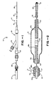
- In the accompanying drawings:
- Figure 1 is a side elevational view of a balloon dilatation catheter, and
- Figure 2 is an enlarged cross sectional view of a portion of the balloon dilatation catheter shown in Figure 1 which, in particular, shows the construction of the balloon.
- As shown in the drawings, a
balloon dilatation catheter 10 comprises a flexible elongate tubular member 11 having a first elongate flexibletubular element 12 which is provided with afirst lumen 13 extending therethrough. The distal portion of thetubular element 12 is provided with a portion 12a of reduced diameter with atapered transition portion 12b which adjoins a portion 12c of a larger diameter extending to the proximal extremity of the first tubular element. - A second elongate flexible
tubular element 16 is also provided which extends over the first elongatetubular element 12 and is disposed coaxially therewith. The second elongatetubular element 16 is of a size so that there is provided between the first and secondtubular elements tubular elements balloon 18 is carried by the distal portion of thetubular element 16 near the distal extremity thereof and has its interior in communication with the lumen 17. Theballoon 18 is formed integral with the secondtubular element 16. - The first and second
tubular elements - The distal extremity of the second elongate
tubular element 16 is shrunk onto the distal extremity of the firsttubular element 12 to form a liquid-tight seal between their distal ends. The lumen 17 opens into theballoon 18 and can be used for inflating and deflating the balloon. If desired, instead of forming theballoon 18 integral with the second elongatetubular element 16, it can be formed as a separate element and bonded to the secondtubular element 16 by suitable means such as an adhesive. - An
adapter 21 is secured to the proximal extremity of the tubular member 11. Theadapter 21 is of a conventional type and is provided with a main orcentral arm 22 and aside arm 23. Themain arm 22 is in communication with thelumen 13 of the firsttubular element 12 and is adapted to carry aguide wire 26. Theguide wire 26 can be formed by a suitable material such as stainless steel and is provided with an elongate portion 26a, a necked down taperedportion 26b and aportion 26c at the distal extremity which is of substantially reduced diameter. A spring-like coil 28 is secured to the distal extremity of theguide wire 26 and is in the form of a helix. The proximal end of thecoil 28 is secured to the distal portion of theguide wire 26 bysolder 29. Asemi-spherical tip 31 is provided at the distal extremity of thecoil 28 and joins the tip of thewire 26 to the coil. Thecoil 28 is formed of a suitable material, for example platinum. Thetip 31 is formed of a suitable material such as gold. - A
band 36, which serves as a marker, is provided on the portion 12a of the firsttubular element 12 and is disposed substantially equidistant between the extremities of theballoon 18. - A
torquer 41 of a conventional type is secured to the proximal extremity of theguide wire 26 and is adapted to be grasped by hand for rotating the guide wire as hereinafter described. - If it is assumed that the
balloon 18 has a diameter of 2 mm when fully inflated, the balloon dilatation catheter shown in Figures 1 and 2 of the drawings can have dimensions such as the following: The tubular member 11 extending from theadapter 21 to theballoon 18 can have a suitable length ranging from 40 to 50 cm and preferably a dimension of approximately 135 cm. The portion 12c of the first or innertubular element 12 can have an outside diameter ranging from 0.064 to 0.86 mm (0.025 to 0.034 inch), an inside diameter of 0.36 to 0.51 mm (0.014 to 0.020 inch) and preferably 0.69 and 0.41 mm (0.027 and 0.016 inch) respectively. The portion 12a can have an outside diameter of 0.41 to 0.56 mm (0.016 to 0.022 inch) and an inside diameter of 0.2 to 0.3 mm (0.008 to 0.012 inch) and preferably dimensions of 0.51 mm (0.020 inch) for the outside diameter and 0.25 mm (0.010 inch) for the inside diameter. The secondtubular element 16 can have an outside diameter of 0.97 to 1.21 mm (0.038 to 0.048 inch) and an inside diameter of 0.84 to 1.07 mm (0.033 to 0.042 inch) and preferably an outside diameter of 1.14 mm (0.045 inch) and an inside diameter 0.97 mm (0.038 inch). Theballoon catheter 10 in which the distal extremities of the first and secondtubular elements guide wire 26 can have a dimension ranging from 0.33 to 0.36 mm (0.013 to 0.014 inch) and if desired can be coated with a suitable material such as PTFE. Theportion 26c of theguide wire 26 can have a dimension such as 0.18 to 0.2 mm (0.007 to 0.008 inch). Thecoil 28 can have an outside diameter of 0.3 to 0.41 mm (0.012 to 0.016 inch) and preferably of approximately 0.38 mm (0.015 inch). Thecoil 28 can have a length ranging from 15 mm to 50 mm and preferably has a length of approximately 30 mm. Theradiopaque marker band 36 can have an internal diameter of 0.53 mm (0.021 inch) with a wall thickness of 0.05 mm (0.002 inch) and a width of approximately 1.14 mm (0.045 inch). - Operation and use of the balloon dilatation catheter as shown in Figures 1 and 2 is now briefly described as follows. Assume that a stenosis is to be crossed. The
catheter 10 with theballoon 18 in a collapsed state is introduced into the vessel in a conventional manner. Theguide wire 26 can be utilized to facilitate the introduction and advancement of thedilatation catheter 10. Its progress can be observed upon a fluoroscope because thecoil 28 is relatively opaque to X-rays. Although theguide wire 26 cannot be retracted from the catheter, it is independently manipulable with respect to the balloon dilatation catheter. For example, if desired the distal extremity of theguide wire 26 and, in particular, thecoil 28 can be advanced so it is 7.6 to 10 cm (3 to 4 inches) ahead of the catheter. It also can be rotated by use of thetorquer 41. - By utilizing such a
guide wire 26 with the dilatation catheter herein described, it is possible to reduce the profile of the dilatation catheter substantially with the only disadvantage being that the guide wire cannot be removed. The amount of travel of theguide wire 26 is determined by the length of theportion 26c of the guide wire. When thetapered portion 26b enters thetapered portion 12b of the firsttubular element 12, further travel is inhibited. The rearmost extremity of theguide wire 26 is determined when thesolder 29 reaches the distal extremity of the first flexibletubular element 12. Typically this ex- tendability or advanceability of the guide wire in the dilatation catheter can vary from 10 to 20 cm. The amount of advancement of theguide wire 26 can also be adjusted within the limits just described by the positioning of thetorquer 41 on the guide wire. - After the dilatation catheter has been positioned in the stenosis, the
balloon 18 can be inflated by introducing a radiopaque contract liquid through theside arm 23. Themarker 36 provided within theballoon 18 facilitates the positioning of the balloon in the stenosis prior to inflation. After theballoon 18 has been inflated one or more times, the balloon can be deflated and the balloon removed from the stenosis and thedilatation catheter 10 removed from the vessel.
Claims (3)
Priority Applications (1)
| Application Number | Priority Date | Filing Date | Title |
|---|---|---|---|
| AT86305874T ATE51758T1 (en) | 1985-07-30 | 1986-07-30 | BALLOON DILATION CATHETER WITH FIXED GUIDE WIRE. |
Applications Claiming Priority (2)
| Application Number | Priority Date | Filing Date | Title |
|---|---|---|---|
| US760397 | 1985-07-30 | ||
| US06/760,397 US4616653A (en) | 1985-07-30 | 1985-07-30 | Balloon dilatation catheter with advanceable non-removable guide wire |
Publications (2)
| Publication Number | Publication Date |
|---|---|
| EP0213749A1 EP0213749A1 (en) | 1987-03-11 |
| EP0213749B1 true EP0213749B1 (en) | 1990-04-11 |
Family
ID=25058991
Family Applications (1)
| Application Number | Title | Priority Date | Filing Date |
|---|---|---|---|
| EP86305874A Expired - Lifetime EP0213749B1 (en) | 1985-07-30 | 1986-07-30 | Balloon dilatation catheter with advanceable non-removable guide wire |
Country Status (6)
| Country | Link |
|---|---|
| US (1) | US4616653A (en) |
| EP (1) | EP0213749B1 (en) |
| JP (1) | JPS6272370A (en) |
| AT (1) | ATE51758T1 (en) |
| AU (1) | AU587051B2 (en) |
| DE (1) | DE3670207D1 (en) |
Families Citing this family (117)
| Publication number | Priority date | Publication date | Assignee | Title |
|---|---|---|---|---|
| US4664113A (en) * | 1984-05-30 | 1987-05-12 | Advanced Cardiovascular Systems, Inc. | Steerable dilatation catheter with rotation limiting device |
| JPS61162956A (en) * | 1985-01-11 | 1986-07-23 | 東レ株式会社 | Leak balloon catheter |
| US4641654A (en) * | 1985-07-30 | 1987-02-10 | Advanced Cardiovascular Systems, Inc. | Steerable balloon dilatation catheter assembly having dye injection and pressure measurement capabilities |
| US4921483A (en) * | 1985-12-19 | 1990-05-01 | Leocor, Inc. | Angioplasty catheter |
| US4724846A (en) * | 1986-01-10 | 1988-02-16 | Medrad, Inc. | Catheter guide wire assembly |
| US5350395A (en) * | 1986-04-15 | 1994-09-27 | Yock Paul G | Angioplasty apparatus facilitating rapid exchanges |
| US5061273A (en) * | 1989-06-01 | 1991-10-29 | Yock Paul G | Angioplasty apparatus facilitating rapid exchanges |
| CH670391A5 (en) * | 1986-07-29 | 1989-06-15 | Sarcem Sa | |
| JPH0771579B2 (en) * | 1986-08-05 | 1995-08-02 | 住友ベークライト株式会社 | Medical balloon catheter |
| ATE84727T1 (en) * | 1986-08-08 | 1993-02-15 | Scimed Life Systems Inc | DILATION GUIDE WIRE FOR ANGIOPLASTY. |
| US4846174A (en) * | 1986-08-08 | 1989-07-11 | Scimed Life Systems, Inc. | Angioplasty dilating guide wire |
| DE3787011T2 (en) * | 1987-01-06 | 1994-03-10 | Advanced Cardiovascular System | Dilatation catheter with a thin guide wire. |
| US4793350A (en) * | 1987-01-06 | 1988-12-27 | Advanced Cardiovascular Systems, Inc. | Liquid filled low profile dilatation catheter |
| US4771777A (en) * | 1987-01-06 | 1988-09-20 | Advanced Cardiovascular Systems, Inc. | Perfusion type balloon dilatation catheter, apparatus and method |
| US4976720A (en) * | 1987-01-06 | 1990-12-11 | Advanced Cardiovascular Systems, Inc. | Vascular catheters |
| WO1988006465A1 (en) * | 1987-02-27 | 1988-09-07 | Terumo Kabushiki Kaisha | Catheter equipped with expansible member and production thereof |
| US4793359A (en) * | 1987-04-24 | 1988-12-27 | Gv Medical, Inc. | Centering balloon structure for transluminal angioplasty catheter |
| US4820349A (en) * | 1987-08-21 | 1989-04-11 | C. R. Bard, Inc. | Dilatation catheter with collapsible outer diameter |
| US4927413A (en) * | 1987-08-24 | 1990-05-22 | Progressive Angioplasty Systems, Inc. | Catheter for balloon angioplasty |
| US4808164A (en) * | 1987-08-24 | 1989-02-28 | Progressive Angioplasty Systems, Inc. | Catheter for balloon angioplasty |
| JPS6458263A (en) * | 1987-08-28 | 1989-03-06 | Terumo Corp | Intravascular introducing catheter |
| EP0309754B1 (en) * | 1987-08-31 | 1993-07-21 | John W. Danforth | Angioplasty dilitation balloon catheter |
| US4892519A (en) * | 1987-12-03 | 1990-01-09 | Advanced Cardiovascular Systems, Inc. | Steerable perfusion dilatation catheter |
| US4832047A (en) * | 1987-12-15 | 1989-05-23 | Target Therapeutics | Guide wire device |
| DE3743578A1 (en) * | 1987-12-22 | 1989-07-13 | Andreas Dr Zeiher | BALLOON CATHETER FOR RECANALIZING STENOSES IN BODY CHANNELS, IN PARTICULAR CORONARY VESSELS AND PERIPHERAL ARTERIAL VESSELS |
| US4796642A (en) * | 1987-12-28 | 1989-01-10 | Cordis Leads, Inc. | Pacing lead stylet |
| US4884573A (en) * | 1988-03-07 | 1989-12-05 | Leocor, Inc. | Very low profile angioplasty balloon catheter with capacity to use steerable, removable guidewire |
| US4998917A (en) * | 1988-05-26 | 1991-03-12 | Advanced Cardiovascular Systems, Inc. | High torque steerable dilatation catheter |
| MY104678A (en) * | 1988-11-10 | 1994-05-31 | Bard Inc C R | Balloon dilatation catheter with integral guidewire. |
| US4932959A (en) * | 1988-12-01 | 1990-06-12 | Advanced Cardiovascular Systems, Inc. | Vascular catheter with releasably secured guidewire |
| WO1990006212A1 (en) * | 1988-12-05 | 1990-06-14 | Institut Gornogo Dela Sibirskogo Otdelenia Akademii Nauk Sssr | Single-stroke pneumatic device |
| US5480382A (en) * | 1989-01-09 | 1996-01-02 | Pilot Cardiovascular Systems, Inc. | Steerable medical device |
| US5308324A (en) * | 1989-01-09 | 1994-05-03 | Pilot Cardiovascular Systems, Inc. | Steerable medical device |
| US5108368A (en) * | 1990-01-04 | 1992-04-28 | Pilot Cardiovascular System, Inc. | Steerable medical device |
| US5203772A (en) * | 1989-01-09 | 1993-04-20 | Pilot Cardiovascular Systems, Inc. | Steerable medical device |
| US4998916A (en) * | 1989-01-09 | 1991-03-12 | Hammerslag Julius G | Steerable medical device |
| US5037391A (en) * | 1989-01-09 | 1991-08-06 | Pilot Cardiovascular Systems, Inc. | Steerable angioplasty device |
| US5454789A (en) * | 1989-01-13 | 1995-10-03 | Scimed Life Systems, Inc. | Innerless dilatation balloon catheter |
| US5085636A (en) * | 1989-01-13 | 1992-02-04 | Scimed Life Systems, Inc. | Balloon catheter with inflation-deflation valve |
| ES2049204T3 (en) * | 1989-01-30 | 1994-07-16 | Bard Inc C R | RAPIDLY CHANGEABLE CORONARY CATHETER. |
| US5728067A (en) * | 1989-01-30 | 1998-03-17 | C. R. Bard, Inc. | Rapidly exchangeable coronary catheter |
| US4994018A (en) * | 1989-05-31 | 1991-02-19 | Datascope Corporation | Intra-aortic balloon assembly |
| US5111829A (en) * | 1989-06-28 | 1992-05-12 | Boston Scientific Corporation | Steerable highly elongated guidewire |
| CA2009798A1 (en) * | 1989-07-26 | 1991-01-26 | Gary Gomringer | Guide wire |
| US4976690A (en) * | 1989-08-10 | 1990-12-11 | Scimed Life Systems, Inc. | Variable stiffness angioplasty catheter |
| US5484409A (en) * | 1989-08-25 | 1996-01-16 | Scimed Life Systems, Inc. | Intravascular catheter and method for use thereof |
| US5059183A (en) * | 1989-09-01 | 1991-10-22 | Neal Semrad | Stop guide wire and double ended obturator-catheter-sheath system and method of use of same |
| US5318529A (en) * | 1989-09-06 | 1994-06-07 | Boston Scientific Corporation | Angioplasty balloon catheter and adaptor |
| US5324263A (en) * | 1989-11-02 | 1994-06-28 | Danforth Biomedical, Inc. | Low profile high performance interventional catheters |
| US5209728B1 (en) * | 1989-11-02 | 1998-04-14 | Danforth Biomedical Inc | Low profile high performance interventional catheters |
| US5026384A (en) * | 1989-11-07 | 1991-06-25 | Interventional Technologies, Inc. | Atherectomy systems and methods |
| WO1991008014A1 (en) * | 1989-11-28 | 1991-06-13 | Leocor, Inc. | Low profile catheter |
| JP2528011B2 (en) * | 1989-12-20 | 1996-08-28 | テルモ株式会社 | Catheter |
| IL93141A0 (en) * | 1990-01-23 | 1990-11-05 | Urcan Medical Ltd | Ultrasonic recanalization system |
| US5045061A (en) * | 1990-02-02 | 1991-09-03 | C. R. Bard, Inc. | Balloon catheter and locking guidewire system |
| US5345945A (en) * | 1990-08-29 | 1994-09-13 | Baxter International Inc. | Dual coil guidewire with radiopaque distal tip |
| US5195989A (en) * | 1990-09-17 | 1993-03-23 | Scimed Life Systems, Inc. | Low profile catheter for increasing lumen size of a blood vessel and guide wire therefor |
| US5163911A (en) * | 1990-10-31 | 1992-11-17 | Baxter International Inc. | Over-the-wire catheter |
| FR2669826B1 (en) * | 1990-11-30 | 1996-07-12 | Leopold Plowiecki | CATHETER FOR DILATION OF THE ARTERIES. |
| US5403339A (en) * | 1991-06-21 | 1995-04-04 | Terumo Kabushiki Kaisha | Blood vessel dilator |
| US5833706A (en) * | 1991-07-05 | 1998-11-10 | Scimed Life Systems, Inc. | Single operator exchange perfusion catheter having a distal catheter shaft section |
| US5490837A (en) * | 1991-07-05 | 1996-02-13 | Scimed Life Systems, Inc. | Single operator exchange catheter having a distal catheter shaft section |
| US5976107A (en) * | 1991-07-05 | 1999-11-02 | Scimed Life Systems. Inc. | Catheter having extendable guide wire lumen |
| US6029671A (en) * | 1991-07-16 | 2000-02-29 | Heartport, Inc. | System and methods for performing endovascular procedures |
| US5324259A (en) * | 1991-12-18 | 1994-06-28 | Advanced Cardiovascular Systems, Inc. | Intravascular catheter with means to seal guidewire port |
| US5242396A (en) * | 1991-12-19 | 1993-09-07 | Advanced Cardiovascular Systems, Inc. | Dilatation catheter with reinforcing mandrel |
| US5417658A (en) * | 1992-03-17 | 1995-05-23 | Scimed Life Systems, Inc. | Balloon dilatation catheter having a torsionally soft component |
| WO1993018816A1 (en) * | 1992-03-17 | 1993-09-30 | Scimed Life Systems, Inc. | Balloon dilatation catheter having a free core wire |
| US5312340A (en) * | 1992-03-17 | 1994-05-17 | Scimed Life Systems, Inc. | Balloon dilatation catheter having dual sealing plugs |
| US5295493A (en) * | 1992-03-19 | 1994-03-22 | Interventional Technologies, Inc. | Anatomical guide wire |
| FR2690072A1 (en) * | 1992-04-16 | 1993-10-22 | Darinot Jean Claude | Artificial insemination gun esp. for inseminating cattle - comprises elongate tube with internal sliding shaft engaging semen-carrying straw, with internal formations restricting shaft movement |
| US5287858A (en) * | 1992-09-23 | 1994-02-22 | Pilot Cardiovascular Systems, Inc. | Rotational atherectomy guidewire |
| US5382234A (en) * | 1993-04-08 | 1995-01-17 | Scimed Life Systems, Inc. | Over-the-wire balloon catheter |
| JPH06296696A (en) * | 1993-04-14 | 1994-10-25 | Noboru Chiba | Catheter |
| US5409470A (en) * | 1993-05-07 | 1995-04-25 | C. R. Bard, Inc. | Dilatation catheter and guidewire with threaded tip connection |
| US5338301A (en) * | 1993-08-26 | 1994-08-16 | Cordis Corporation | Extendable balloon-on-a-wire catheter, system and treatment procedure |
| US5465733A (en) * | 1993-10-14 | 1995-11-14 | Hinohara; Tomoaki | Guide wire for catheters and method for its use |
| US5507301A (en) * | 1993-11-19 | 1996-04-16 | Advanced Cardiovascular Systems, Inc. | Catheter and guidewire system with flexible distal portions |
| US5460185A (en) * | 1994-03-25 | 1995-10-24 | Cordis Corporation | Tool and method facilitating rapid PCTA catheter exchange |
| US5667493A (en) * | 1994-12-30 | 1997-09-16 | Janacek; Jaroslav | Dilation catheter |
| US5951513A (en) * | 1995-02-24 | 1999-09-14 | Advanced Cardiovascular Systems, Inc. | Balloon catheter having non-bonded integral balloon and methods for its manufacture |
| US5830155A (en) * | 1995-10-27 | 1998-11-03 | Cordis Corporation | Guidewire assembly |
| US5836892A (en) * | 1995-10-30 | 1998-11-17 | Cordis Corporation | Guidewire with radiopaque markers |
| US5810790A (en) * | 1996-11-19 | 1998-09-22 | Ebling; Wendell V. | Catheter with viewing system and port connector |
| US6355016B1 (en) | 1997-03-06 | 2002-03-12 | Medtronic Percusurge, Inc. | Catheter core wire |
| US6190332B1 (en) | 1998-02-19 | 2001-02-20 | Percusurge, Inc. | Core wire with shapeable tip |
| US6228072B1 (en) | 1998-02-19 | 2001-05-08 | Percusurge, Inc. | Shaft for medical catheters |
| US20050119615A1 (en) * | 2000-04-06 | 2005-06-02 | Norborn Medical, Inc. | Guidewire for crossing occlusions or stenoses |
| US20080140101A1 (en) * | 2006-12-07 | 2008-06-12 | Revascular Therapeutic, Inc. | Apparatus for crossing occlusions or stenoses |
| US6746422B1 (en) | 2000-08-23 | 2004-06-08 | Norborn Medical, Inc. | Steerable support system with external ribs/slots that taper |
| US6824550B1 (en) | 2000-04-06 | 2004-11-30 | Norbon Medical, Inc. | Guidewire for crossing occlusions or stenosis |
| US20070225615A1 (en) * | 2006-03-22 | 2007-09-27 | Revascular Therapeutics Inc. | Guidewire controller system |
| US20060074442A1 (en) * | 2000-04-06 | 2006-04-06 | Revascular Therapeutics, Inc. | Guidewire for crossing occlusions or stenoses |
| US9254143B2 (en) | 1998-02-25 | 2016-02-09 | Revascular Therapeutics, Inc. | Guidewire for crossing occlusions or stenoses having a shapeable distal end |
| US6059767A (en) * | 1998-02-25 | 2000-05-09 | Norborn Medical, Inc. | Steerable unitary infusion catheter/guide wire incorporating detachable infusion port assembly |
| US6113579A (en) * | 1998-03-04 | 2000-09-05 | Scimed Life Systems, Inc. | Catheter tip designs and methods for improved stent crossing |
| US6517515B1 (en) | 1998-03-04 | 2003-02-11 | Scimed Life Systems, Inc. | Catheter having variable size guide wire lumen |
| US5947927A (en) * | 1998-03-23 | 1999-09-07 | Scimed Life Systems, Inc. | Convertible catheter having a single proximal lumen |
| US7381198B2 (en) | 2000-08-23 | 2008-06-03 | Revascular Therapeutics, Inc. | Steerable distal support system |
| US6595983B2 (en) | 2000-12-07 | 2003-07-22 | Jan K. Voda | Guide or diagnostic catheter for right coronary artery |
| US7150723B2 (en) * | 2001-11-29 | 2006-12-19 | C-I-Medic Co., Ltd. | Medical device including guide wire and balloon catheter for curing a coronary artery |
| JP4418366B2 (en) | 2002-08-13 | 2010-02-17 | ウィルソン−クック・メディカル・インコーポレーテッド | ERCP catheter with removable handle for basket-compatible basket |
| US7734332B2 (en) * | 2002-10-18 | 2010-06-08 | Ariomedica Ltd. | Atherectomy system with imaging guidewire |
| US8591540B2 (en) | 2003-02-27 | 2013-11-26 | Abbott Cardiovascular Systems Inc. | Embolic filtering devices |
| US7582740B2 (en) * | 2003-04-17 | 2009-09-01 | The Trustees Of Columbia University In The City Of New York | Methods and kits for detecting SARS-associated coronavirus |
| US20050209674A1 (en) * | 2003-09-05 | 2005-09-22 | Kutscher Tuvia D | Balloon assembly (V) |
| US7867218B1 (en) | 2004-02-24 | 2011-01-11 | Voda Heart Technology, Llc | Steerable catheter for right coronary artery |
| WO2006119503A1 (en) * | 2005-05-04 | 2006-11-09 | Abbott Laboratories | Guidewire apparatus with an expandable portion |
| US20070288036A1 (en) * | 2006-06-09 | 2007-12-13 | Niranjan Seshadri | Assembly for crossing a chronic total occlusion and method therefor |
| US20060282110A1 (en) * | 2006-07-11 | 2006-12-14 | Conor Medsystems, Inc. | Advanceable, non-removable guide wire balloon catheter delivery system for a stent and method |
| US20080015675A1 (en) * | 2006-07-11 | 2008-01-17 | Conor Medsystems, Inc. | Balloon catheter system and method |
| DE102006054533A1 (en) * | 2006-11-15 | 2008-05-21 | Resoimplant Gmbh | Fixation element for bone fragment |
| GB2450351B (en) | 2007-06-20 | 2012-01-18 | Cozart Bioscience Ltd | Monitoring an Immunoassay |
| JP5353100B2 (en) * | 2008-07-25 | 2013-11-27 | 株式会社カネカ | Balloon catheter |
| US8657821B2 (en) | 2008-11-14 | 2014-02-25 | Revascular Therapeutics Inc. | Method and system for reversibly controlled drilling of luminal occlusions |
| US8162891B2 (en) | 2008-11-26 | 2012-04-24 | Revascular Therapeutics, Inc. | Delivery and exchange catheter for storing guidewire |
| US10849771B2 (en) | 2011-06-27 | 2020-12-01 | Boston Scientific Scimed, Inc. | Stent delivery systems and methods for making and using stent delivery systems |
Family Cites Families (9)
| Publication number | Priority date | Publication date | Assignee | Title |
|---|---|---|---|---|
| US2856934A (en) * | 1957-09-24 | 1958-10-21 | Petillo Diomede | Catheters |
| US3452740A (en) * | 1966-05-31 | 1969-07-01 | Us Catheter & Instr Corp | Spring guide manipulator |
| US4194513A (en) * | 1977-05-05 | 1980-03-25 | Indiana University Foundation | Antenatal cell extracting device and method |
| US4411055A (en) * | 1980-05-19 | 1983-10-25 | Advanced Cardiovascular Systems, Inc. | Vascular guiding catheter assembly and vascular dilating catheter assembly and a combination thereof and methods for making the same |
| US4545390A (en) * | 1982-09-22 | 1985-10-08 | C. R. Bard, Inc. | Steerable guide wire for balloon dilatation procedure |
| CH652933A5 (en) * | 1983-05-27 | 1985-12-13 | Wilson Cook Medical Inc | Probe head. |
| US4538622A (en) * | 1983-11-10 | 1985-09-03 | Advanced Cardiovascular Systems, Inc. | Guide wire for catheters |
| US4664113A (en) * | 1984-05-30 | 1987-05-12 | Advanced Cardiovascular Systems, Inc. | Steerable dilatation catheter with rotation limiting device |
| US4641654A (en) * | 1985-07-30 | 1987-02-10 | Advanced Cardiovascular Systems, Inc. | Steerable balloon dilatation catheter assembly having dye injection and pressure measurement capabilities |
-
1985
- 1985-07-30 US US06/760,397 patent/US4616653A/en not_active Expired - Lifetime
-
1986
- 1986-07-25 AU AU60550/86A patent/AU587051B2/en not_active Ceased
- 1986-07-30 EP EP86305874A patent/EP0213749B1/en not_active Expired - Lifetime
- 1986-07-30 DE DE8686305874T patent/DE3670207D1/en not_active Expired - Lifetime
- 1986-07-30 AT AT86305874T patent/ATE51758T1/en not_active IP Right Cessation
- 1986-07-30 JP JP61179788A patent/JPS6272370A/en active Granted
Also Published As
| Publication number | Publication date |
|---|---|
| US4616653A (en) | 1986-10-14 |
| AU6055086A (en) | 1987-02-05 |
| DE3670207D1 (en) | 1990-05-17 |
| ATE51758T1 (en) | 1990-04-15 |
| EP0213749A1 (en) | 1987-03-11 |
| AU587051B2 (en) | 1989-08-03 |
| JPH0363909B2 (en) | 1991-10-03 |
| JPS6272370A (en) | 1987-04-02 |
Similar Documents
| Publication | Publication Date | Title |
|---|---|---|
| EP0213749B1 (en) | Balloon dilatation catheter with advanceable non-removable guide wire | |
| US5520645A (en) | Low profile angioplasty catheter and/or guide wire and method | |
| US5449343A (en) | Steerable dilatation catheter | |
| US4771776A (en) | Dilatation catheter with angled balloon and method | |
| EP0213752B1 (en) | Steerable balloon dilatation catheter assembly having dye injection and pressure measurement capabilities | |
| EP0274129B1 (en) | Reinforced balloon dilatation catheter with slitted exchange sleeve and method | |
| US5242394A (en) | Steerable dilatation catheter | |
| US5465733A (en) | Guide wire for catheters and method for its use | |
| EP0213750B1 (en) | Self-venting balloon dilatation catheter | |
| US5439447A (en) | Balloon dilation catheter with hypotube | |
| US4998923A (en) | Steerable dilatation catheter | |
| US5779688A (en) | Low profile balloon-on-a-wire catheter with shapeable and/or deflectable tip and method | |
| AU610846B2 (en) | Liquid filled low profile dilatation catheter | |
| US5002532A (en) | Tandem balloon dilatation catheter | |
| CA1315632C (en) | Kissing balloon catheter | |
| US4775371A (en) | Stiffened dilatation catheter and method of manufacture | |
| US4946466A (en) | Transluminal angioplasty apparatus | |
| EP0274130A2 (en) | Steerable low profile balloon dilatation catheter | |
| JPH0626576B2 (en) | Device for performing angiogenesis | |
| CA1262854A (en) | Steerable soft-tip catheter and method of using same | |
| EP0277370B1 (en) | Tandem balloon dilatation catheter | |
| US6932836B2 (en) | Catheter and stent delivery system | |
| CA1245937A (en) | Balloon dilatation catheter with advanceable non- removable guide wire | |
| EP0288833A1 (en) | Balloon dilatation catheter with laser cutting capability |
Legal Events
| Date | Code | Title | Description |
|---|---|---|---|
| PUAI | Public reference made under article 153(3) epc to a published international application that has entered the european phase |
Free format text: ORIGINAL CODE: 0009012 |
|
| AK | Designated contracting states |
Kind code of ref document: A1 Designated state(s): AT CH DE FR GB IT LI NL |
|
| 17P | Request for examination filed |
Effective date: 19870720 |
|
| 17Q | First examination report despatched |
Effective date: 19890303 |
|
| GRAA | (expected) grant |
Free format text: ORIGINAL CODE: 0009210 |
|
| AK | Designated contracting states |
Kind code of ref document: B1 Designated state(s): AT CH DE FR GB IT LI NL |
|
| REF | Corresponds to: |
Ref document number: 51758 Country of ref document: AT Date of ref document: 19900415 Kind code of ref document: T |
|
| REF | Corresponds to: |
Ref document number: 3670207 Country of ref document: DE Date of ref document: 19900517 |
|
| ET | Fr: translation filed | ||
| ITF | It: translation for a ep patent filed |
Owner name: MODIANO & ASSOCIATI S.R.L. |
|
| PLBE | No opposition filed within time limit |
Free format text: ORIGINAL CODE: 0009261 |
|
| STAA | Information on the status of an ep patent application or granted ep patent |
Free format text: STATUS: NO OPPOSITION FILED WITHIN TIME LIMIT |
|
| 26N | No opposition filed | ||
| ITTA | It: last paid annual fee | ||
| PGFP | Annual fee paid to national office [announced via postgrant information from national office to epo] |
Ref country code: GB Payment date: 19980921 Year of fee payment: 13 |
|
| PGFP | Annual fee paid to national office [announced via postgrant information from national office to epo] |
Ref country code: FR Payment date: 19980925 Year of fee payment: 13 Ref country code: DE Payment date: 19980925 Year of fee payment: 13 |
|
| PGFP | Annual fee paid to national office [announced via postgrant information from national office to epo] |
Ref country code: NL Payment date: 19980929 Year of fee payment: 13 Ref country code: AT Payment date: 19980929 Year of fee payment: 13 |
|
| PGFP | Annual fee paid to national office [announced via postgrant information from national office to epo] |
Ref country code: CH Payment date: 19981009 Year of fee payment: 13 |
|
| PG25 | Lapsed in a contracting state [announced via postgrant information from national office to epo] |
Ref country code: GB Free format text: LAPSE BECAUSE OF NON-PAYMENT OF DUE FEES Effective date: 19990730 Ref country code: AT Free format text: LAPSE BECAUSE OF NON-PAYMENT OF DUE FEES Effective date: 19990730 |
|
| PG25 | Lapsed in a contracting state [announced via postgrant information from national office to epo] |
Ref country code: LI Free format text: LAPSE BECAUSE OF NON-PAYMENT OF DUE FEES Effective date: 19990731 Ref country code: FR Free format text: THE PATENT HAS BEEN ANNULLED BY A DECISION OF A NATIONAL AUTHORITY Effective date: 19990731 Ref country code: CH Free format text: LAPSE BECAUSE OF NON-PAYMENT OF DUE FEES Effective date: 19990731 |
|
| PG25 | Lapsed in a contracting state [announced via postgrant information from national office to epo] |
Ref country code: NL Free format text: LAPSE BECAUSE OF NON-PAYMENT OF DUE FEES Effective date: 20000201 |
|
| REG | Reference to a national code |
Ref country code: CH Ref legal event code: PL |
|
| GBPC | Gb: european patent ceased through non-payment of renewal fee |
Effective date: 19990730 |
|
| NLV4 | Nl: lapsed or anulled due to non-payment of the annual fee |
Effective date: 20000201 |
|
| PG25 | Lapsed in a contracting state [announced via postgrant information from national office to epo] |
Ref country code: DE Free format text: LAPSE BECAUSE OF NON-PAYMENT OF DUE FEES Effective date: 20000503 |
|
| REG | Reference to a national code |
Ref country code: FR Ref legal event code: ST |
|
| PG25 | Lapsed in a contracting state [announced via postgrant information from national office to epo] |
Ref country code: IT Free format text: LAPSE BECAUSE OF NON-PAYMENT OF DUE FEES;WARNING: LAPSES OF ITALIAN PATENTS WITH EFFECTIVE DATE BEFORE 2007 MAY HAVE OCCURRED AT ANY TIME BEFORE 2007. THE CORRECT EFFECTIVE DATE MAY BE DIFFERENT FROM THE ONE RECORDED. Effective date: 20050730 |