EP0215537B1 - An intubating device - Google Patents
An intubating device Download PDFInfo
- Publication number
- EP0215537B1 EP0215537B1 EP86301716A EP86301716A EP0215537B1 EP 0215537 B1 EP0215537 B1 EP 0215537B1 EP 86301716 A EP86301716 A EP 86301716A EP 86301716 A EP86301716 A EP 86301716A EP 0215537 B1 EP0215537 B1 EP 0215537B1
- Authority
- EP
- European Patent Office
- Prior art keywords
- stylet
- holder
- hub
- tube
- extending
- Prior art date
- Legal status (The legal status is an assumption and is not a legal conclusion. Google has not performed a legal analysis and makes no representation as to the accuracy of the status listed.)
- Expired - Lifetime
Links
- 239000002184 metal Substances 0.000 claims description 19
- 239000007788 liquid Substances 0.000 claims description 13
- 239000012530 fluid Substances 0.000 claims description 10
- 238000000034 method Methods 0.000 description 7
- 206010010071 Coma Diseases 0.000 description 2
- 239000004698 Polyethylene Substances 0.000 description 1
- 206010042618 Surgical procedure repeated Diseases 0.000 description 1
- 230000005587 bubbling Effects 0.000 description 1
- 210000004051 gastric juice Anatomy 0.000 description 1
- 210000003736 gastrointestinal content Anatomy 0.000 description 1
- 239000000314 lubricant Substances 0.000 description 1
- 239000000463 material Substances 0.000 description 1
- 239000004033 plastic Substances 0.000 description 1
- 229920003023 plastic Polymers 0.000 description 1
- -1 polyethylene Polymers 0.000 description 1
- 229920000573 polyethylene Polymers 0.000 description 1
- 229920002635 polyurethane Polymers 0.000 description 1
- 239000004814 polyurethane Substances 0.000 description 1
- 229920000915 polyvinyl chloride Polymers 0.000 description 1
- 239000004800 polyvinyl chloride Substances 0.000 description 1
- 238000011084 recovery Methods 0.000 description 1
- 210000002784 stomach Anatomy 0.000 description 1
- 238000001356 surgical procedure Methods 0.000 description 1
- XLYOFNOQVPJJNP-UHFFFAOYSA-N water Substances O XLYOFNOQVPJJNP-UHFFFAOYSA-N 0.000 description 1
Images
Classifications
-
- A—HUMAN NECESSITIES
- A61—MEDICAL OR VETERINARY SCIENCE; HYGIENE
- A61J—CONTAINERS SPECIALLY ADAPTED FOR MEDICAL OR PHARMACEUTICAL PURPOSES; DEVICES OR METHODS SPECIALLY ADAPTED FOR BRINGING PHARMACEUTICAL PRODUCTS INTO PARTICULAR PHYSICAL OR ADMINISTERING FORMS; DEVICES FOR ADMINISTERING FOOD OR MEDICINES ORALLY; BABY COMFORTERS; DEVICES FOR RECEIVING SPITTLE
- A61J15/00—Feeding-tubes for therapeutic purposes
- A61J15/0003—Nasal or oral feeding-tubes, e.g. tube entering body through nose or mouth
- A61J15/0007—Nasal or oral feeding-tubes, e.g. tube entering body through nose or mouth inserted by using a guide-wire
Definitions
- the invention relates to intubating devices and more particularly to a new and improved intubating device of the type that permits aspiration of gastric juices to determine if the device is properly positioned.
- Intubating or naso-gastric devices in one form or another have been known for centuries and are used to provide nourishment to human patients, many of whom may be comatose or semi-comatose or who are otherwise unable to take nourishment. For example, following surgery a patient may need such a device for a brief period of time during recovery.
- such devices consist of four parts or elements, namely, a flexible feeding tube for conveying nourishment, a stylet preferably made of metal for positioning the feeding tube, a Bolus tube or weight for positioning the feeding tube in the duodena or jejunal and a connector for attachment of a supply of nourishment to the feeding tube.
- intubating or naso-gastric devices it is, of course, essential that the device be properly positioned in order that it can accomplish its desired function. It is also important that the device be properly positioned as quickly and expeditiously as possible. Due to the fact that the device extends into the patient, it is not possible to visually observe the positioning of the device. For this reason, it has become necessary to develop ways and means of determining the position of the intubating device within the patient.
- One way of determining the position of the intubating device is to make the feeding tube of a radio- opaque material so that its position can be determined by X-ray or the like. This procedure is time consuming and subjects the patient to additional X-rays.
- Another procedure for determining the position of the intubating device is to feed air through the feeding tube.
- the physician can then listen for the bubbling air with a stethoscope or the like and determine the position of the tube.
- Another procedure for determining the position of the intubating device is to aspirate the stomach through the feeding tube and determine the location by removing the contents with a syringe or the like.
- US-A 4,388,076 Another United States patent of interest is US-A 4,388,076. This patent purports to be directed to the problem of repositioning the intubating device in the event that it is found to have been incorrectly positioned in the first instance.
- This patent discloses a flexible feeding tube having discharge openings at one end.
- a metal stylet positioned in telescoping relationship within the feeding tube.
- the proximal end of the flexible feeding tube is attached to a connector which, in turn, is adapted to be connected to a syringe so that the syringe communicates with the interior of the flexible feeding tube.
- the metal stylet extends through the flexible tube and into the bore of the connector.
- the terminal end of the metal stylet is formed into a hook which is positioned and secured within the passageway of the connector.
- the stylet is removed before the process of feeding liquid nourishment to the patient.
- the positioning of the hook member is a task requiring a certain amount of manipulative skill and, with the stylet in this position, there is the possibility of clogging the passageway.
- Another object of this invention is to provide a new and improved intubating device wherein a metal stylet is used to position a flexible tube which is secured to the connector so as not to obstruct the passageway through the connector.
- a still further object of this invention is to provide a new and improved intubating device which can be manufactured and assembled simply and expeditiously.
- Another object of this invention is to provide a new and improved intubating device having a flexible tube, a connector and a positioning stylet wherein the connector has an unobstructed passageway to the flexible tube.
- a further object of this invention is to provide a new and improved intubating device having a flexible tube, a connector and a stylet wherein the stylet is embedded in the connector so that it does not interfere with the passage of liquids.
- the invention therefore provides an intubating device having a stylet which may be positioned within a human patient without removal of the stylet during aspiration of samples to determine the correct position of the device
- a tube connector having connected at one end thereof a flexible feeding tube for conveying liquid nourishment to the patient and having an opening at the other end
- a stylet holder having a circular flange portion extending from the stylet holder for hand manipulation of the stylet holder
- a fluid passageway extending through the said stylet holder and having an opening in the other end of the stylet holder for receipt of a supply of liquid nourishment at the said opening and for flow through the said fuid passageway
- the stylet holder with the stylet being adapted to be
- a flexible feeding tube 4 which may be made of some suitable plastic, such as polyvinylchloride, polyethylene or polyurethane.
- the terminal end of the flexible feeding tube may have suitable openings for discharge of liquid nourishment passed through the tube.
- connector member 6 adapted to be connected at one end to a source of liquid noruishment, such as a syringe.
- the other end of the connector member 6 is adapted to be connected to the flexible feeding tube 4.
- One end of the connector member 6 has a female recess 8 for receipt of the flexible feeding tube 4 and the other end of the tubular connector has a female recess 10 for receipt of the male member of the metal positioning stylet to be described subsequently.
- the device For the purpose of closing the intubating device when not in use, the device is provided with a plug 12 attached to a flexible strap member 14.
- the tube connector 6 has a male member 16 adapted to fit within the female recess 18.
- the terminal end of the flexible feeding tube 4 is in telescoping relationship with a bolus tube 20 having a plurality of small weights 22.
- the purpose of the Bolus tube and weights is to assist in positioning the feeding tube in the desired position within the patient.
- the Bolus tube and weights provide a degree of rigidity to the flexible feeding tube for this purpose.
- this means includes a stylet holder 24 having a circular flange extending therefrom. This circular flange is used to position the device by hand manipulation.
- the stylet holder includes a female recess 26 at the terminal end adapted to receive a male tube or nozzle from a source of liquid nourishment such as a syringe or the like. Extending through the stylet is a fluid passageway 28. The purpose of the passageway 28 is threefold: It is used for supplying water as a lubricant; it is used to aspirate the stomach contents to determine positioning of the stylet; and it is used for ausculation to determine placement.
- the other end of the stylet holder includes a hub 30.
- Means is provided for connecting a metal stylet to the stylet holder in a permanent manner in order not to interfere with the flow of fluid for the purposes described above.
- this means includes a metal stylet consisting of a twisted metal wire 32.
- the wire is twisted to provide a rough outer surface.
- the hub member 30 has a blind hole 34 having a smaller inner diameter than the outer diameter of the metal stylet 32.
- the metal stylet is fixedly embedded in the blind hole 34 and the rough twisted surface of the metal stylet ensures the fixed position of the stylet with respect to the stylet holder.
- the stylet With the metal stylet attached to the hub of the stylet in a position offset from the center of the stylet holder and the hub member, the stylet does not interfere with the flow of fluid through the passageway 28 to allow for the aspiration of fluids from the patient through the passageway to determine if the assembly is correctly positioned and before liquid nourishment is connected to the assembly for flow through the feeding tube.
- the hub 30 of the stylet holder is placed within the female recess of the tube connector so that the metal stylet is positioned within the flexible tube to form an intubating assembly.
- the assembly is then placed within the human patient and manipulated until it is believed to be properly positioned.
- the patient is then aspirated by a syringe or the like and the contents analyzed to determine if the intubating assembly is properly positioned. If the intubating device is not properly positioned, it may be repositioned, without removing the stylet, and the procedure repeated until the intubating assembly is properly positioned.
- the stylet is removed and liquid nourishment may be supplied to the patient in the usual manner.
Landscapes
- Health & Medical Sciences (AREA)
- Life Sciences & Earth Sciences (AREA)
- Animal Behavior & Ethology (AREA)
- General Health & Medical Sciences (AREA)
- Public Health (AREA)
- Veterinary Medicine (AREA)
- Media Introduction/Drainage Providing Device (AREA)
- Infusion, Injection, And Reservoir Apparatuses (AREA)
Description
- The invention relates to intubating devices and more particularly to a new and improved intubating device of the type that permits aspiration of gastric juices to determine if the device is properly positioned.
- Intubating or naso-gastric devices in one form or another have been known for centuries and are used to provide nourishment to human patients, many of whom may be comatose or semi-comatose or who are otherwise unable to take nourishment. For example, following surgery a patient may need such a device for a brief period of time during recovery. Typically, such devices consist of four parts or elements, namely, a flexible feeding tube for conveying nourishment, a stylet preferably made of metal for positioning the feeding tube, a Bolus tube or weight for positioning the feeding tube in the duodena or jejunal and a connector for attachment of a supply of nourishment to the feeding tube.
- In the use of intubating or naso-gastric devices it is, of course, essential that the device be properly positioned in order that it can accomplish its desired function. It is also important that the device be properly positioned as quickly and expeditiously as possible. Due to the fact that the device extends into the patient, it is not possible to visually observe the positioning of the device. For this reason, it has become necessary to develop ways and means of determining the position of the intubating device within the patient.
- One way of determining the position of the intubating device is to make the feeding tube of a radio- opaque material so that its position can be determined by X-ray or the like. This procedure is time consuming and subjects the patient to additional X-rays.
- Another procedure for determining the position of the intubating device is to feed air through the feeding tube. The physician can then listen for the bubbling air with a stethoscope or the like and determine the position of the tube.
- Another procedure for determining the position of the intubating device is to aspirate the stomach through the feeding tube and determine the location by removing the contents with a syringe or the like.
- The problem with the above procedures for determining the position of the intubating device is that most of these procedures require removal of the metal stylet before they can be carried out. If it is determined that the intubating device is improperly positioned then the stylet must be reinserted in the feeding tube. The reinsertion of the stylet may result in considerable discomfort and possible danger to the patient.
- There are numerous prior art U.S. patents relating to intubating or naso-gastric devices including: US-A 4,249,535; US-A 3,503,385; US-A 3,395,711; US-A 4,033,331; US-A 3,896,815; US-A 3,957,055; US-A 3,964,488; US-A 2,688,329; US-A 3,070,089.
- Another United States patent of interest is US-A 4,388,076. This patent purports to be directed to the problem of repositioning the intubating device in the event that it is found to have been incorrectly positioned in the first instance.
- This patent discloses a flexible feeding tube having discharge openings at one end. There is a metal stylet positioned in telescoping relationship within the feeding tube. The proximal end of the flexible feeding tube is attached to a connector which, in turn, is adapted to be connected to a syringe so that the syringe communicates with the interior of the flexible feeding tube. The metal stylet extends through the flexible tube and into the bore of the connector.
- The terminal end of the metal stylet is formed into a hook which is positioned and secured within the passageway of the connector. The stylet is removed before the process of feeding liquid nourishment to the patient.
- The positioning of the hook member is a task requiring a certain amount of manipulative skill and, with the stylet in this position, there is the possibility of clogging the passageway.
- With the foregoing in mind, it is an object of this invention to provide a simple, easily constructed intubating device.
- It is another object of this invention to provide a new and improved intubating device for positioning the feeding tube and for supplying liquid nourishment to a patient.
- Another object of this invention is to provide a new and improved intubating device wherein a metal stylet is used to position a flexible tube which is secured to the connector so as not to obstruct the passageway through the connector.
- A still further object of this invention is to provide a new and improved intubating device which can be manufactured and assembled simply and expeditiously.
- Another object of this invention is to provide a new and improved intubating device having a flexible tube, a connector and a positioning stylet wherein the connector has an unobstructed passageway to the flexible tube.
- A further object of this invention is to provide a new and improved intubating device having a flexible tube, a connector and a stylet wherein the stylet is embedded in the connector so that it does not interfere with the passage of liquids.
- The invention therefore provides an intubating device having a stylet which may be positioned within a human patient without removal of the stylet during aspiration of samples to determine the correct position of the device comprising: a tube connector having connected at one end thereof a flexible feeding tube for conveying liquid nourishment to the patient and having an opening at the other end; a stylet holder having a circular flange portion extending from the stylet holder for hand manipulation of the stylet holder; a hub at one other end of the stylet holder extending from the circular flange; a blind hole in the hub extending from the end of the hub towards the circular flange, the blind hole being offset from the centre of the hub; a fluid passageway extending through the said stylet holder and having an opening in the other end of the stylet holder for receipt of a supply of liquid nourishment at the said opening and for flow through the said fuid passageway; a metal stylet embedded in the blind hole and extending from it; the stylet holder with the stylet being adapted to be positioned in interlocking relationship with the tube connector and the feeding tube with the fluid passageway unobstructed. When the intubating device is initially positioned, an aspiration process may be accomplished through the unobstructed fluid passageway and, after after the device is properly positioned, liquid nourishment may flow unobstructed through the passageway.
- The accompanying drawings exemplify a preferred embodiment of the invention. In the drawings:
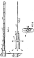
- Figure 1 is a plan view of the intubating device;
- Figure 2 is a side view of the stylet member; and
- Figure 3 is a sectional view taken along line 3-3 of Figure 2.
- Referring to the illustrative drawings, there is shown a flexible feeding tube 4 which may be made of some suitable plastic, such as polyvinylchloride, polyethylene or polyurethane. The terminal end of the flexible feeding tube may have suitable openings for discharge of liquid nourishment passed through the tube.
- There is a
connector member 6 adapted to be connected at one end to a source of liquid noruishment, such as a syringe. - The other end of the
connector member 6 is adapted to be connected to the flexible feeding tube 4. One end of theconnector member 6 has a female recess 8 for receipt of the flexible feeding tube 4 and the other end of the tubular connector has a female recess 10 for receipt of the male member of the metal positioning stylet to be described subsequently. - For the purpose of closing the intubating device when not in use, the device is provided with a
plug 12 attached to aflexible strap member 14. For this purpose thetube connector 6 has a male member 16 adapted to fit within the female recess 18. The terminal end of the flexible feeding tube 4 is in telescoping relationship with abolus tube 20 having a plurality of small weights 22. The purpose of the Bolus tube and weights is to assist in positioning the feeding tube in the desired position within the patient. The Bolus tube and weights provide a degree of rigidity to the flexible feeding tube for this purpose. - Means is provided for insuring proper positioning of the flexible feeding tube within the patient. As embodied, this means includes a
stylet holder 24 having a circular flange extending therefrom. This circular flange is used to position the device by hand manipulation. The stylet holder includes afemale recess 26 at the terminal end adapted to receive a male tube or nozzle from a source of liquid nourishment such as a syringe or the like. Extending through the stylet is afluid passageway 28. The purpose of thepassageway 28 is threefold: It is used for supplying water as a lubricant; it is used to aspirate the stomach contents to determine positioning of the stylet; and it is used for ausculation to determine placement. The other end of the stylet holder includes a hub 30. - Means is provided for connecting a metal stylet to the stylet holder in a permanent manner in order not to interfere with the flow of fluid for the purposes described above.
- As embodied, this means includes a metal stylet consisting of a
twisted metal wire 32. Conveniently, the wire is twisted to provide a rough outer surface. The hub member 30 has a blind hole 34 having a smaller inner diameter than the outer diameter of themetal stylet 32. The metal stylet is fixedly embedded in the blind hole 34 and the rough twisted surface of the metal stylet ensures the fixed position of the stylet with respect to the stylet holder. With the metal stylet attached to the hub of the stylet in a position offset from the center of the stylet holder and the hub member, the stylet does not interfere with the flow of fluid through thepassageway 28 to allow for the aspiration of fluids from the patient through the passageway to determine if the assembly is correctly positioned and before liquid nourishment is connected to the assembly for flow through the feeding tube. - In use, the hub 30 of the stylet holder is placed within the female recess of the tube connector so that the metal stylet is positioned within the flexible tube to form an intubating assembly. The assembly is then placed within the human patient and manipulated until it is believed to be properly positioned. The patient is then aspirated by a syringe or the like and the contents analyzed to determine if the intubating assembly is properly positioned. If the intubating device is not properly positioned, it may be repositioned, without removing the stylet, and the procedure repeated until the intubating assembly is properly positioned.
- After the device is properly positioned, the stylet is removed and liquid nourishment may be supplied to the patient in the usual manner.
Claims (3)
Applications Claiming Priority (2)
| Application Number | Priority Date | Filing Date | Title |
|---|---|---|---|
| US776774 | 1985-09-17 | ||
| US06/776,774 US4636200A (en) | 1985-09-17 | 1985-09-17 | Intubating device |
Publications (3)
| Publication Number | Publication Date |
|---|---|
| EP0215537A2 EP0215537A2 (en) | 1987-03-25 |
| EP0215537A3 EP0215537A3 (en) | 1987-11-04 |
| EP0215537B1 true EP0215537B1 (en) | 1990-02-07 |
Family
ID=25108325
Family Applications (1)
| Application Number | Title | Priority Date | Filing Date |
|---|---|---|---|
| EP86301716A Expired - Lifetime EP0215537B1 (en) | 1985-09-17 | 1986-03-11 | An intubating device |
Country Status (6)
| Country | Link |
|---|---|
| US (1) | US4636200A (en) |
| EP (1) | EP0215537B1 (en) |
| JP (1) | JPS6266866A (en) |
| AU (1) | AU587862B2 (en) |
| CA (1) | CA1253049A (en) |
| DE (1) | DE3668780D1 (en) |
Families Citing this family (27)
| Publication number | Priority date | Publication date | Assignee | Title |
|---|---|---|---|---|
| US4790825A (en) * | 1986-09-05 | 1988-12-13 | Electro Catheter Corporation | Closed chest cannulation method and device for atrial-major artery bypass |
| US4819619A (en) * | 1987-01-16 | 1989-04-11 | Augustine Scott D | Device for inserting a nasal tube |
| FR2622117B1 (en) * | 1987-10-27 | 1997-01-31 | Cordis Sa | CANNULA AND PEN CATHETER INTRODUCER |
| US4986279A (en) * | 1989-03-01 | 1991-01-22 | National-Standard Company | Localization needle assembly with reinforced needle assembly |
| US4966582A (en) * | 1989-06-30 | 1990-10-30 | Sit James K | Injection site platform |
| US5059183A (en) * | 1989-09-01 | 1991-10-22 | Neal Semrad | Stop guide wire and double ended obturator-catheter-sheath system and method of use of same |
| US5092847A (en) * | 1990-04-06 | 1992-03-03 | Sherwood Medical Company | Enteral feeding tube stylet |
| US5242389A (en) * | 1990-07-19 | 1993-09-07 | Sherwood Medical Company | Enteral feeding tube enteral feeding tube with separate stylet lumen |
| JPH07108319B2 (en) * | 1990-09-13 | 1995-11-22 | 住友ベークライト株式会社 | Catheter for intestinal insertion |
| JP2518244Y2 (en) * | 1990-10-16 | 1996-11-27 | テルモ株式会社 | Guide wire assembly |
| US5382238A (en) * | 1993-05-20 | 1995-01-17 | Quinton Instrument Company | Catheter stiffeners |
| US5512045A (en) * | 1993-12-22 | 1996-04-30 | Gurchumelidze; Teimuraz P. | Surgical decompression and irrigation apparatus and method |
| JP3318921B2 (en) * | 1995-02-21 | 2002-08-26 | ニプロ株式会社 | Stylet and stylet connector |
| US5658253A (en) * | 1995-02-21 | 1997-08-19 | Abbott Laboratories | Stylet device for guiding an enteral feeding tube |
| US6193691B1 (en) * | 1999-03-30 | 2001-02-27 | Depuy Orthopaedics, Inc. | Catheter system |
| US7179269B2 (en) * | 2002-05-20 | 2007-02-20 | Scimed Life Systems, Inc. | Apparatus and system for removing an obstruction from a lumen |
| US20090165784A1 (en) * | 2007-12-28 | 2009-07-02 | Tyco Healthcare Group Lp | Lubricious intubation device |
| US20080103448A1 (en) * | 2006-10-30 | 2008-05-01 | Schorn Greg M | Stylet Having a Roughened Outer Surface |
| WO2009067247A1 (en) * | 2007-11-21 | 2009-05-28 | Becton, Dickinson And Company | Safety stylet |
| WO2009148969A1 (en) * | 2008-06-02 | 2009-12-10 | Sta-Med, Llc | Needle cover assembly for a syringe |
| US20100100049A1 (en) * | 2008-10-22 | 2010-04-22 | Godfrey Mark W | Securement device for vascular access system |
| US7955317B2 (en) * | 2009-06-30 | 2011-06-07 | Tyco Healthcare Group Lp | Female adaptor for feeding line |
| US8162882B2 (en) | 2010-06-23 | 2012-04-24 | Sta-Med, Llc | Automatic-locking safety needle covers and methods of use and manufacture |
| WO2012166746A1 (en) | 2011-05-31 | 2012-12-06 | Sta-Med, Llc | Blood collection safety devices and methods of use and manufacture |
| AU2013101567B4 (en) * | 2013-05-27 | 2014-03-13 | P & M Hebbard Pty Ltd | A catheter system |
| US10758706B2 (en) * | 2016-11-16 | 2020-09-01 | Boston Scientific Scimed, Inc. | Catheter compatible stiffening stylet with packaging and device hold elements |
| MX2021013473A (en) * | 2019-05-06 | 2022-01-06 | Bles Biochemicals Incorporated | Feeding tube with integrated stylet. |
Family Cites Families (6)
| Publication number | Priority date | Publication date | Assignee | Title |
|---|---|---|---|---|
| US3572333A (en) * | 1968-10-14 | 1971-03-23 | Becton Dickinson Co | Obturator |
| US3757768A (en) * | 1972-04-07 | 1973-09-11 | Medical Evaluation Devices And | Manipulable spring guide-catheter and tube for intravenous feeding |
| US4559046A (en) * | 1979-08-20 | 1985-12-17 | Catheter Technology Corporation | Apparatus for intravenous therapy and hyperalimentation |
| US4388076A (en) * | 1981-02-11 | 1983-06-14 | Biosearch Medical Products Inc. | Intubating device |
| US4390017A (en) * | 1981-08-07 | 1983-06-28 | Harrison Eugene O | Enteral feeding system |
| US4496347A (en) * | 1982-09-24 | 1985-01-29 | Viridian, Inc. | Feeding tube stylet |
-
1985
- 1985-09-17 US US06/776,774 patent/US4636200A/en not_active Expired - Fee Related
-
1986
- 1986-03-11 EP EP86301716A patent/EP0215537B1/en not_active Expired - Lifetime
- 1986-03-11 DE DE8686301716T patent/DE3668780D1/en not_active Expired - Lifetime
- 1986-03-18 CA CA000504427A patent/CA1253049A/en not_active Expired
- 1986-03-20 JP JP61063859A patent/JPS6266866A/en active Granted
- 1986-09-16 AU AU62736/86A patent/AU587862B2/en not_active Ceased
Also Published As
| Publication number | Publication date |
|---|---|
| JPH0340627B2 (en) | 1991-06-19 |
| CA1253049A (en) | 1989-04-25 |
| AU587862B2 (en) | 1989-08-31 |
| US4636200A (en) | 1987-01-13 |
| EP0215537A3 (en) | 1987-11-04 |
| JPS6266866A (en) | 1987-03-26 |
| DE3668780D1 (en) | 1990-03-15 |
| AU6273686A (en) | 1987-03-19 |
| EP0215537A2 (en) | 1987-03-25 |
Similar Documents
| Publication | Publication Date | Title |
|---|---|---|
| EP0215537B1 (en) | An intubating device | |
| US5242389A (en) | Enteral feeding tube enteral feeding tube with separate stylet lumen | |
| US4388076A (en) | Intubating device | |
| US4270542A (en) | Gastro-intestinal tubes | |
| US5078701A (en) | Wire guided intestinal catheter | |
| US7699818B2 (en) | Insertion system and methods for nasogastric tubes | |
| US4249535A (en) | Gastric feeding device | |
| US7740620B2 (en) | Insertion system and methods for nasogastric tubes including feeding tubes | |
| US7695459B2 (en) | Nasogastric tube insertion system and method | |
| US4874365A (en) | Feeding tube facilitating improved placement and permitting subsequent delivery of a second prescribed product and method therefor | |
| EP0400369A3 (en) | Gastrostomy tube | |
| EP1464315A2 (en) | Polyurethane feeding tube and associated adaptors | |
| EP0242051A1 (en) | Enteral feeding tube assembly and suction tube therefor | |
| USRE32306E (en) | Intubating device | |
| EP2811925B1 (en) | Apparatus for administering fluid to a medical tube | |
| US20210322280A1 (en) | Feeding tube with inflatable balloon component and at least one of a carbon dioxide sampling line and a suction tube component | |
| GB2032780A (en) | Gastro-intestinal tube | |
| US6500164B1 (en) | Suction device | |
| CA2087335C (en) | Enteral feeding tube | |
| CN217366589U (en) | Integral structure of nasal feeding tube |
Legal Events
| Date | Code | Title | Description |
|---|---|---|---|
| PUAI | Public reference made under article 153(3) epc to a published international application that has entered the european phase |
Free format text: ORIGINAL CODE: 0009012 |
|
| AK | Designated contracting states |
Kind code of ref document: A2 Designated state(s): DE FR GB IT |
|
| RAP1 | Party data changed (applicant data changed or rights of an application transferred) |
Owner name: SHERWOOD MEDICAL COMPANY |
|
| PUAL | Search report despatched |
Free format text: ORIGINAL CODE: 0009013 |
|
| AK | Designated contracting states |
Kind code of ref document: A3 Designated state(s): DE FR GB IT |
|
| 17P | Request for examination filed |
Effective date: 19880407 |
|
| 17Q | First examination report despatched |
Effective date: 19880725 |
|
| GRAA | (expected) grant |
Free format text: ORIGINAL CODE: 0009210 |
|
| AK | Designated contracting states |
Kind code of ref document: B1 Designated state(s): DE FR GB IT |
|
| REF | Corresponds to: |
Ref document number: 3668780 Country of ref document: DE Date of ref document: 19900315 |
|
| ET | Fr: translation filed | ||
| ITF | It: translation for a ep patent filed |
Owner name: MODIANO & ASSOCIATI S.R.L. |
|
| PLBE | No opposition filed within time limit |
Free format text: ORIGINAL CODE: 0009261 |
|
| STAA | Information on the status of an ep patent application or granted ep patent |
Free format text: STATUS: NO OPPOSITION FILED WITHIN TIME LIMIT |
|
| 26N | No opposition filed | ||
| ITTA | It: last paid annual fee | ||
| REG | Reference to a national code |
Ref country code: GB Ref legal event code: 732E |
|
| REG | Reference to a national code |
Ref country code: GB Ref legal event code: 732E |
|
| REG | Reference to a national code |
Ref country code: FR Ref legal event code: TP |
|
| REG | Reference to a national code |
Ref country code: GB Ref legal event code: IF02 |
|
| PGFP | Annual fee paid to national office [announced via postgrant information from national office to epo] |
Ref country code: GB Payment date: 20050302 Year of fee payment: 20 |
|
| PGFP | Annual fee paid to national office [announced via postgrant information from national office to epo] |
Ref country code: FR Payment date: 20050321 Year of fee payment: 20 |
|
| PGFP | Annual fee paid to national office [announced via postgrant information from national office to epo] |
Ref country code: IT Payment date: 20050329 Year of fee payment: 20 |
|
| PGFP | Annual fee paid to national office [announced via postgrant information from national office to epo] |
Ref country code: DE Payment date: 20050502 Year of fee payment: 20 |
|
| PG25 | Lapsed in a contracting state [announced via postgrant information from national office to epo] |
Ref country code: GB Free format text: LAPSE BECAUSE OF EXPIRATION OF PROTECTION Effective date: 20060310 |
|
| REG | Reference to a national code |
Ref country code: GB Ref legal event code: PE20 |