EP0215745B1 - Machine for washing, breaking and fulling of fabrics, with pneumatic dragging - Google Patents
Machine for washing, breaking and fulling of fabrics, with pneumatic dragging Download PDFInfo
- Publication number
- EP0215745B1 EP0215745B1 EP86830235A EP86830235A EP0215745B1 EP 0215745 B1 EP0215745 B1 EP 0215745B1 EP 86830235 A EP86830235 A EP 86830235A EP 86830235 A EP86830235 A EP 86830235A EP 0215745 B1 EP0215745 B1 EP 0215745B1
- Authority
- EP
- European Patent Office
- Prior art keywords
- fabric
- machine
- per
- duct
- dragging
- Prior art date
- Legal status (The legal status is an assumption and is not a legal conclusion. Google has not performed a legal analysis and makes no representation as to the accuracy of the status listed.)
- Expired
Links
Images

Classifications
-
- D—TEXTILES; PAPER
- D06—TREATMENT OF TEXTILES OR THE LIKE; LAUNDERING; FLEXIBLE MATERIALS NOT OTHERWISE PROVIDED FOR
- D06B—TREATING TEXTILE MATERIALS USING LIQUIDS, GASES OR VAPOURS
- D06B3/00—Passing of textile materials through liquids, gases or vapours to effect treatment, e.g. washing, dyeing, bleaching, sizing, impregnating
- D06B3/28—Passing of textile materials through liquids, gases or vapours to effect treatment, e.g. washing, dyeing, bleaching, sizing, impregnating of fabrics propelled by, or with the aid of, jets of the treating material
-
- D—TEXTILES; PAPER
- D06—TREATMENT OF TEXTILES OR THE LIKE; LAUNDERING; FLEXIBLE MATERIALS NOT OTHERWISE PROVIDED FOR
- D06C—FINISHING, DRESSING, TENTERING OR STRETCHING TEXTILE FABRICS
- D06C17/00—Fulling
-
- D—TEXTILES; PAPER
- D06—TREATMENT OF TEXTILES OR THE LIKE; LAUNDERING; FLEXIBLE MATERIALS NOT OTHERWISE PROVIDED FOR
- D06C—FINISHING, DRESSING, TENTERING OR STRETCHING TEXTILE FABRICS
- D06C19/00—Breaking or softening of fabrics
Definitions
- the invention relates to a machine that is of use for carrying out a treatment operation of the fabric, suitable to prepare said fabric for the finishing, and in particular to a machine that operates a washing, a bringing together of wefts and warp yarns of the fabric, and an at least partial fulling of the fabric ; this machine is of use for the treatment of light fabrics and also of heavy fabrics and in particular of relatively stiff fabrics.
- Similar machines usually provide a wall, against which the fabric is pushed or thrown more or less violently, which fabric there undergoes the mentioned treatment before going back to the lower tank shaped part with water and cleansing agents wherefrom the fabric is taken again to be once more thrown towards the wall.
- the inclination of this wall can be adjustable, in respect to the throwing direction of the fabric.
- the purpose of the machine, object of this invention is to carry out with greater efficiency the mentioned treatment and then obtain a better result on the fabric, even with shorter times of treatment.
- a machine comprises - in combination with a wall towards which the fabric is directed in order to strike against said wall and undergo the action thereof - a duct for the dragging of the fabric ; means to feed said fabric to said duct ; and means to convey a dragging air stream towards the outlet of said duct for the dragging of the fabric, in order to project it pneumatically against said wall, that is grid shaped and angularly adjustable.
- the direction of the projection of the fabric can be oriented towards the grid-shaped wall and upwards.
- Said means of conveyance can have a portion forming an annular nozzle around the outlet of the fabric duct ; a shaping of the dragging duct and a shaping of a pneumatic pipe surrounding said duct for the dragging of the fabric can cooperate to carry out the portion forming the nozzle ; these two shapings can be axially adjustable to each other.
- the means of feeding the fabric can include a couple of cylinders - per se known - through which the fabric is passed, and the speed of said cylinders is settled depending on the fabric requirement.
- a means to push the air - like a fan - sucks it from the inside and/or the outside of the working casing, and is connected to said pipe upstream in respect to the shapings.
- the machine can also comprise means for supporting the fabric, along the trajectory of the projection towards the grid.
- Said means can be pneumatic. They can include longitudinal ducts or canalizations at least in the lower area of the duct for the pneumatic projection, and/or a lower grid type structure to blow the air into the duct of pneumatic projection, and/or a second nozzle for the impulsion of the fabric.
- number 1 indicates a tank defined by the bottom of a chamber which can be closed at the upper side 1A and shows suitable means for the entrance, with inspection and checking doors.
- the upper closing wall 1A slants upwards and towards the end 1 B of the casing itself, and at this end 1 B a grid type wall 3 is placed, articulated at 5 and thus so predisposed that its slant can be angularly adjusted in respect to the vertical line.
- an air jet for the transportation is carried out, which is of use for dragging and projecting a fabric against the grid wall 3, being the fabric part of one piece (or several pieces) that is closed in such a way as to form a ring - simple or multiple - and is contained in the casing 1, 1A, being the fabric able to plunge into the liquid contained in the bottom of the tank 1, to be repeatedly recycled and projected against the grid wall 3.
- the fabric, indicated by T, is drawn upwards according to the arrowfT by an assembly of two dragging cylinders 7 and 8, one of them at least being driven into rotation at an adjustable speed and the other being urged towards the first one and possibly being driven into rotation at the same peripheral speed to drag the lifted fabric and feed it according to a trajectory T1 to a duct 9 for the pneumatic dragging of the fabric.
- This duct 9 shows an enlarged area 9A with a double truncated cone profile, which extends and ends with an outlet 9B adjacent to the truncated cone portion which is tapering towards said outlet.
- the axis of the duct 9, 9A, 9B is oriented towards the grid wall 3 and upwards.
- the duct 9, 9A, 9B is surrounded by a pipe 10 that is fed by compressed air through a duct 12 that is deviated in respect to the axis of the assembly 9,10, and comes from a fan 14 ; said fan sucks from an inlet 16 lying below the assembly 9, 10 inside the casing 1, 1A, or still inside the casing 1, 1 A - above the assembly 9, 10, or sucks from the outside or partially form the inside and partially from the outside.
- the pipe 12, 10 extends beyond the outlet 9B with a portion 10A extending towards the grid 3 and upwards as shown in the drawing.
- the stream of air pushed by the fan 14 forms a means of pneumatic conveyance for the fabric that comes out from the outlet 9B of the duct 9, 9A, and is dragged by the stream of air coming from the duct 12 and that flows into the annular way between the duct 9 and the pipe 10, through the nozzle formed by the two shapings 9A and 10B, the latter being formed by the pipe 10, to carry out a truncated cone nozzle converging towards the outlet 9B and by this way suitable to act energetically on the fabric coming out from the same outlet 9B ; the fabric is dragged by the air stream along the duct 10 and in particular along the end portion 10A of the duct, and is violently projected against the grid 3, where the action of treatment of the fabric takes place.
- the assembly of the cylinders 7 and 8 drags the fabric by lifting it according to the arrow fT and feeding it to the duct 9, 9A, 9B for the extent that is required by the effect of dragging caused by the air stream on the same fabric.
- the fabric can be fed for the required extent by the system of pneumatic dragging or for a lower extent, so that a certain tension is maintained in the projected fabric.
- the fabric is violently treated by the grid 3 and then falls again towards the lower portion of the casing 1, where it gets soaked by the liquid contained in the bottom of this casing forming a tank ; the fabric can also be invested with a liquid projected or distributed by fall, along the trajectory upstream the cylinders 7 and 8.
- the fabric drawn by the two cylinders 7 and 8 can be even partially squeezed by these two cylinders before being driven into the duct 9 by the effect of the pneumatic dragging.
- the two shapings 9A and 10B can be adjusted in a mutual axial position, in order to vary the dragging effect by the air conveyed by the nozzle formed by these two shapings.
- devices are provided to assure a support, especially a pneumatic support of the fabric thrown towards the grid.
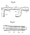
- a second annular nozzle 61 can be provided at the end of the duct 10A, which is fed by a duct 12A.
- it can be provided to divide the air jet of the duct 12, thus realizing (Fig. 6) a jacket 110A around the duct 10A, to form a second nozzle 63.
- the second annular nozzle 61 can even be simply fed by air coming from the outside ; in that case there is no need of the duct 12A.
Description
- The invention relates to a machine that is of use for carrying out a treatment operation of the fabric, suitable to prepare said fabric for the finishing, and in particular to a machine that operates a washing, a bringing together of wefts and warp yarns of the fabric, and an at least partial fulling of the fabric ; this machine is of use for the treatment of light fabrics and also of heavy fabrics and in particular of relatively stiff fabrics.
- Similar machines usually provide a wall, against which the fabric is pushed or thrown more or less violently, which fabric there undergoes the mentioned treatment before going back to the lower tank shaped part with water and cleansing agents wherefrom the fabric is taken again to be once more thrown towards the wall. The inclination of this wall can be adjustable, in respect to the throwing direction of the fabric.
- The purpose of the machine, object of this invention, is to carry out with greater efficiency the mentioned treatment and then obtain a better result on the fabric, even with shorter times of treatment. These and other purposes and advantages will be evident to the experts through the reading of the text that follows.
- Basically a machine according to the invention comprises - in combination with a wall towards which the fabric is directed in order to strike against said wall and undergo the action thereof - a duct for the dragging of the fabric ; means to feed said fabric to said duct ; and means to convey a dragging air stream towards the outlet of said duct for the dragging of the fabric, in order to project it pneumatically against said wall, that is grid shaped and angularly adjustable.
- The direction of the projection of the fabric can be oriented towards the grid-shaped wall and upwards.
- Said means of conveyance can have a portion forming an annular nozzle around the outlet of the fabric duct ; a shaping of the dragging duct and a shaping of a pneumatic pipe surrounding said duct for the dragging of the fabric can cooperate to carry out the portion forming the nozzle ; these two shapings can be axially adjustable to each other.
- The means of feeding the fabric can include a couple of cylinders - per se known - through which the fabric is passed, and the speed of said cylinders is settled depending on the fabric requirement.
- A means to push the air - like a fan - sucks it from the inside and/or the outside of the working casing, and is connected to said pipe upstream in respect to the shapings.
- The machine can also comprise means for supporting the fabric, along the trajectory of the projection towards the grid. Said means can be pneumatic. They can include longitudinal ducts or canalizations at least in the lower area of the duct for the pneumatic projection, and/or a lower grid type structure to blow the air into the duct of pneumatic projection, and/or a second nozzle for the impulsion of the fabric.
- The invention will be better understood by following the description and the enclosed drawings, that show a practical non restricting exemplification of the same invention.
- In the drawing :
- Fig. 1 shows a whole side cross section view ;
- Figs. 2 to 6 show transversal and longitudinal sections of some different ways of carrying out an effect of pneumatic support.
- According to what is illustrated in Fig. 1 in the enclosed drawing,
number 1 indicates a tank defined by the bottom of a chamber which can be closed at the upper side 1A and shows suitable means for the entrance, with inspection and checking doors. The upper closing wall 1A slants upwards and towards theend 1 B of the casing itself, and at thisend 1 B agrid type wall 3 is placed, articulated at 5 and thus so predisposed that its slant can be angularly adjusted in respect to the vertical line. - Corresponding and oriented towards the
wall 3 an air jet for the transportation is carried out, which is of use for dragging and projecting a fabric against thegrid wall 3, being the fabric part of one piece (or several pieces) that is closed in such a way as to form a ring - simple or multiple - and is contained in thecasing 1, 1A, being the fabric able to plunge into the liquid contained in the bottom of thetank 1, to be repeatedly recycled and projected against thegrid wall 3. The fabric, indicated by T, is drawn upwards according to the arrowfT by an assembly of twodragging cylinders 7 and 8, one of them at least being driven into rotation at an adjustable speed and the other being urged towards the first one and possibly being driven into rotation at the same peripheral speed to drag the lifted fabric and feed it according to a trajectory T1 to aduct 9 for the pneumatic dragging of the fabric. Thisduct 9 shows an enlarged area 9A with a double truncated cone profile, which extends and ends with anoutlet 9B adjacent to the truncated cone portion which is tapering towards said outlet. The axis of theduct grid wall 3 and upwards. Theduct pipe 10 that is fed by compressed air through aduct 12 that is deviated in respect to the axis of theassembly fan 14 ; said fan sucks from aninlet 16 lying below theassembly casing 1, 1A, or still inside thecasing 1, 1 A - above theassembly pipe outlet 9B with aportion 10A extending towards thegrid 3 and upwards as shown in the drawing. The stream of air pushed by thefan 14 forms a means of pneumatic conveyance for the fabric that comes out from theoutlet 9B of theduct 9, 9A, and is dragged by the stream of air coming from theduct 12 and that flows into the annular way between theduct 9 and thepipe 10, through the nozzle formed by the twoshapings 9A and 10B, the latter being formed by thepipe 10, to carry out a truncated cone nozzle converging towards theoutlet 9B and by this way suitable to act energetically on the fabric coming out from thesame outlet 9B ; the fabric is dragged by the air stream along theduct 10 and in particular along theend portion 10A of the duct, and is violently projected against thegrid 3, where the action of treatment of the fabric takes place. The assembly of thecylinders 7 and 8 drags the fabric by lifting it according to the arrow fT and feeding it to theduct - The fabric is violently treated by the
grid 3 and then falls again towards the lower portion of thecasing 1, where it gets soaked by the liquid contained in the bottom of this casing forming a tank ; the fabric can also be invested with a liquid projected or distributed by fall, along the trajectory upstream thecylinders 7 and 8. The fabric drawn by the twocylinders 7 and 8 can be even partially squeezed by these two cylinders before being driven into theduct 9 by the effect of the pneumatic dragging. - The two
shapings 9A and 10B can be adjusted in a mutual axial position, in order to vary the dragging effect by the air conveyed by the nozzle formed by these two shapings. - According to a development of the invention, devices are provided to assure a support, especially a pneumatic support of the fabric thrown towards the grid.
- For this purpose, it is possible to provide for example the achievement of the
portion 10A with undulations forminglongitudinal channels 51, along the whole periphery of the section (Fig. 2) orchannels 53 along the lower portion only (Fig. 3) or a grid system 55 (Fig. 4) especially longitudinal and with anunderlying canalization 57 for the air that comes from theduct 12 or other source of air under pressure. As an alternative solution (Fig. 5) a secondannular nozzle 61 can be provided at the end of theduct 10A, which is fed by aduct 12A. As another alternative solution, it can be provided to divide the air jet of theduct 12, thus realizing (Fig. 6) ajacket 110A around theduct 10A, to form asecond nozzle 63. - The drawing shows only an exemplification, given as a practical demonstration of the invention that can vary in the forms and dispositions. The possible mention of reference numbers in the enclosed claims has the purpose of facilitating the reading of the claims with reference to the description and the drawing, and therefore does not have the purpose of placing limits to the scope of the protection represented by the claims.
- The second
annular nozzle 61 can even be simply fed by air coming from the outside ; in that case there is no need of theduct 12A.
Claims (13)
Applications Claiming Priority (2)
| Application Number | Priority Date | Filing Date | Title |
|---|---|---|---|
| IT09483/85A IT1187084B (en) | 1985-08-27 | 1985-08-27 | MACHINE FOR WASHING, BREAKING AND FOLLING OF FABRICS, WITH PNEUMATIC DRAGING |
| IT948385 | 1985-08-27 |
Publications (2)
| Publication Number | Publication Date |
|---|---|
| EP0215745A1 EP0215745A1 (en) | 1987-03-25 |
| EP0215745B1 true EP0215745B1 (en) | 1989-03-15 |
Family
ID=11130812
Family Applications (1)
| Application Number | Title | Priority Date | Filing Date |
|---|---|---|---|
| EP86830235A Expired EP0215745B1 (en) | 1985-08-27 | 1986-08-27 | Machine for washing, breaking and fulling of fabrics, with pneumatic dragging |
Country Status (7)
| Country | Link |
|---|---|
| US (1) | US4766743A (en) |
| EP (1) | EP0215745B1 (en) |
| CN (1) | CN1018464B (en) |
| DE (1) | DE3662407D1 (en) |
| ES (1) | ES2001579A6 (en) |
| IT (1) | IT1187084B (en) |
| PT (1) | PT83249B (en) |
Cited By (7)
| Publication number | Priority date | Publication date | Assignee | Title |
|---|---|---|---|---|
| EP0312509A1 (en) * | 1987-10-13 | 1989-04-19 | Officina Meccanica Biancalani & C. di Fiorenzo Biancalani & C. S.n.c. | Method for the ageing, softening, washing and fulling of fabrics, with pneumatic transfer of the fabric and machine for carrying out the method |
| EP0665319A2 (en) * | 1993-12-10 | 1995-08-02 | Icbt Madinox | Device for treating and softening an endless textile web |
| US5678429A (en) * | 1995-01-19 | 1997-10-21 | Zonco Federico & Figlio S.N.C. | Machine for the wet and dry treatment of fabrics in rope or open-width form |
| US5937492A (en) * | 1997-05-09 | 1999-08-17 | Flainox, S.R.L. | Finishing machine with pneumatic entrainment of fabric in strand form |
| EP0535287B2 (en) † | 1991-09-21 | 2001-08-08 | Solipat Ag | Method and apparatus for improving handle and surface of fabrics and knitgoods |
| DE19813477C2 (en) * | 1998-03-27 | 2001-11-08 | Then Maschinen Und Appbau Gmbh | Method and device for treating strand-like textile material |
| CN104160082A (en) * | 2012-01-10 | 2014-11-19 | 比安卡拉尼有限公司 | Fabric treatment machine provided with impact members |
Families Citing this family (26)
| Publication number | Priority date | Publication date | Assignee | Title |
|---|---|---|---|---|
| US5014525A (en) * | 1989-10-24 | 1991-05-14 | Madinox S.A. | Machine for dyeing fabric in a rope |
| US5299339A (en) * | 1990-05-14 | 1994-04-05 | S. Sclayos S.A. | Jet dyeing apparatus and method |
| US5440771A (en) * | 1990-05-14 | 1995-08-15 | S. Sclavos S.A. | Jet dyeing apparatus and method |
| DE4119152C2 (en) * | 1991-06-11 | 1993-11-25 | Krantz H Gmbh & Co | Device for the wet treatment of textile goods |
| DE4426336A1 (en) * | 1993-08-23 | 1995-03-02 | Thies Gmbh & Co | Process for treating a textile web and device for carrying it out |
| US5621937A (en) * | 1994-04-04 | 1997-04-22 | S. Sclavos, S.A. | Jet dyeing apparatus and method |
| US5577282A (en) * | 1995-05-22 | 1996-11-26 | Gaston County Dyeing Machine Company | Textile wet processing machine and method |
| US5713223A (en) * | 1995-08-30 | 1998-02-03 | Lin; Teng Chi | Dyeing machine with reversible dye spouter |
| US5893933A (en) * | 1996-05-23 | 1999-04-13 | Solipat Ag | Device and method for the continuous fulling of a material web of textile woven fabrics and knitted fabrics |
| FR2778417B1 (en) * | 1998-05-05 | 2000-12-22 | Alliance Machines Textiles | HOSE WET TREATMENT MACHINE |
| IT1305000B1 (en) * | 1998-09-17 | 2001-04-05 | Flainox Srl | PROCESS AND MACHINE FOR FINISHING FABRIC. |
| IT1304999B1 (en) * | 1998-09-17 | 2001-04-05 | Flainox Srl | FABRIC FINISHING MACHINE. |
| IT1314963B1 (en) * | 2000-06-21 | 2003-01-21 | Biancalani F & C Off Mec | MACHINE FOR THE CONTINUOUS TREATMENT OF A FABRIC |
| ITFI20010168A1 (en) * | 2001-09-12 | 2003-03-12 | Coramtex Srl | MACHINE AND METHOD FOR THE CONTINUOUS TREATMENT OF A FABRIC |
| DE10349374B4 (en) * | 2003-10-21 | 2009-04-09 | Then Maschinen (B.V.I.) Ltd., Road Town | Wet treatment machine for rope-shaped textile goods |
| BRPI0619973B1 (en) * | 2005-12-16 | 2018-07-10 | Southern Mills, Inc. | METHOD FOR PRODUCING A THERMAL PROTECTIVE FABRIC, THERMAL PROTECTIVE FABRIC AND METHODS FOR INCREASING THERMAL PROTECTION FOR A THERMAL PROTECTIVE WEAR. |
| DE102007036408B3 (en) * | 2007-08-02 | 2008-12-18 | Then Maschinen Gmbh | Apparatus for treating rope-shaped textile goods |
| ITFI20070198A1 (en) | 2007-09-04 | 2009-03-05 | Coramtex Srl | "FABRIC TREATMENT MACHINE WITH A ROTATING DRUM AROUND A NON-PARALLEL AXIS OF THE DRUM GEOMETRIC AXIS" |
| ITFI20070197A1 (en) | 2007-09-04 | 2009-03-05 | Coramtex Srl | "MACHINE AND METHOD FOR THE CONTINUOUS TREATMENT OF ROPE FABRICS" |
| WO2009157883A1 (en) * | 2008-06-23 | 2009-12-30 | Canlar Makina Sanayi Ve Ticaret Limited Sirketi | Fabric dyeing machine having full-scale inner drum which doesn't contain fabric carrying pipe |
| CN101798740B (en) * | 2010-03-31 | 2012-08-01 | 泰安康平纳机械有限公司 | Multifunctional fulling and softening finishing machine |
| ITFI20120096A1 (en) * | 2012-05-18 | 2013-11-19 | Coramtex Srl | "TREATMENT LINE TO RETURN AND VOLUMINIZE A FABRIC AND ITS FABRIC TREATMENT METHOD" |
| US20190289374A1 (en) | 2012-08-02 | 2019-09-19 | Joseph L. Vilella | Mutually secure optical data network and method |
| CN103757782B (en) * | 2013-12-27 | 2016-05-04 | 浙江百盛实业有限公司 | Wool fulling milling, the integrated apparatus of rubbing, reel |
| CN103952891A (en) * | 2014-04-18 | 2014-07-30 | 吴江市科时达纺织有限公司 | Fabric finishing device |
| US10793984B2 (en) | 2016-08-04 | 2020-10-06 | Pvh Corporation | Non-iron fabrics and garments, and a method of finishing the same |
Family Cites Families (11)
| Publication number | Priority date | Publication date | Assignee | Title |
|---|---|---|---|---|
| US3718012A (en) * | 1970-09-21 | 1973-02-27 | M Vinas | Device for the wet treatment of textile materials |
| US3685325A (en) * | 1971-04-27 | 1972-08-22 | Synalloy Corp | Apparatus for liquid treatment of textile material webs |
| US3952558A (en) * | 1973-03-28 | 1976-04-27 | Avesta Jernverks Aktiebolag | Machine for dyeing or other wet-treatment of textiles |
| TR18620A (en) * | 1974-05-04 | 1977-05-13 | Thies A Jun | PROCEDURE AND INSTALLATION FOR THE TREATMENT OF LONG RANGE WEAVING STATES |
| FR2317407A1 (en) * | 1975-07-07 | 1977-02-04 | Textile Processing Ab | Dyeing textile by advancing in closed path in dyeing chamber - by dye circulation and in which gas fills remainder of chamber |
| US4129017A (en) * | 1977-01-27 | 1978-12-12 | Burlington Industries, Inc. | Lab sample jet dyeing machine |
| GB2031969B (en) * | 1978-10-18 | 1983-03-09 | Hisaka Works Ltd | Jet treatment of textiles |
| DE2908888A1 (en) * | 1979-03-07 | 1980-09-18 | Thies Kg | METHOD AND DEVICE FOR THE SURFACE TREATMENT OF ENDLESS TEXTILE MATERIALS |
| IT1135149B (en) * | 1981-01-23 | 1986-08-20 | Attilio Bertoldi | MACHINE FOR FOLLING, WASHING AND PRE-DRYING OF ROPE FABRICS |
| US4570404A (en) * | 1983-03-07 | 1986-02-18 | Knudson Gary Art | Two-part hold-down apparatus with slip joint for seamed panel assemblies |
| US4545221A (en) * | 1983-07-21 | 1985-10-08 | Burlington Industries, Inc. | Adjustment and cleaning of the venturi gap in a dyeing machine |
-
1985
- 1985-08-27 IT IT09483/85A patent/IT1187084B/en active
-
1986
- 1986-08-25 PT PT83249A patent/PT83249B/en not_active IP Right Cessation
- 1986-08-25 US US06/900,360 patent/US4766743A/en not_active Expired - Lifetime
- 1986-08-25 CN CN86105196A patent/CN1018464B/en not_active Expired
- 1986-08-25 ES ES8601328A patent/ES2001579A6/en not_active Expired
- 1986-08-27 DE DE8686830235T patent/DE3662407D1/en not_active Expired
- 1986-08-27 EP EP86830235A patent/EP0215745B1/en not_active Expired
Cited By (7)
| Publication number | Priority date | Publication date | Assignee | Title |
|---|---|---|---|---|
| EP0312509A1 (en) * | 1987-10-13 | 1989-04-19 | Officina Meccanica Biancalani & C. di Fiorenzo Biancalani & C. S.n.c. | Method for the ageing, softening, washing and fulling of fabrics, with pneumatic transfer of the fabric and machine for carrying out the method |
| EP0535287B2 (en) † | 1991-09-21 | 2001-08-08 | Solipat Ag | Method and apparatus for improving handle and surface of fabrics and knitgoods |
| EP0665319A2 (en) * | 1993-12-10 | 1995-08-02 | Icbt Madinox | Device for treating and softening an endless textile web |
| US5678429A (en) * | 1995-01-19 | 1997-10-21 | Zonco Federico & Figlio S.N.C. | Machine for the wet and dry treatment of fabrics in rope or open-width form |
| US5937492A (en) * | 1997-05-09 | 1999-08-17 | Flainox, S.R.L. | Finishing machine with pneumatic entrainment of fabric in strand form |
| DE19813477C2 (en) * | 1998-03-27 | 2001-11-08 | Then Maschinen Und Appbau Gmbh | Method and device for treating strand-like textile material |
| CN104160082A (en) * | 2012-01-10 | 2014-11-19 | 比安卡拉尼有限公司 | Fabric treatment machine provided with impact members |
Also Published As
| Publication number | Publication date |
|---|---|
| CN1018464B (en) | 1992-09-30 |
| US4766743A (en) | 1988-08-30 |
| CN86105196A (en) | 1987-03-04 |
| PT83249B (en) | 1992-10-30 |
| PT83249A (en) | 1986-09-01 |
| ES2001579A6 (en) | 1988-06-01 |
| EP0215745A1 (en) | 1987-03-25 |
| DE3662407D1 (en) | 1989-04-20 |
| IT8509483A0 (en) | 1985-08-27 |
| IT1187084B (en) | 1987-12-16 |
Similar Documents
| Publication | Publication Date | Title |
|---|---|---|
| EP0215745B1 (en) | Machine for washing, breaking and fulling of fabrics, with pneumatic dragging | |
| FI66948C (en) | SYSTEM FOER TORRFORMNING AV PAPPER ELLER ANNAT ARMMATERIAL AV PARTIKLAR ELLER FIBER | |
| US4365424A (en) | Method for surface treatment of an endless textile structure | |
| US20220025563A1 (en) | Jet suction box and jet suction process | |
| NO161389B (en) | PROCEDURE FOR THE PREPARATION OF A MATERIAL COVER AND DEVICE FOR IMPLEMENTING THE PROCEDURE. | |
| EP1425454B1 (en) | Machine and method for the continuous treatment of a fabric | |
| US3157440A (en) | Fibrous raw material feeding arrangements for spinning machines | |
| US4468937A (en) | Machine for the fulling and washing of cord fabrics | |
| US3979930A (en) | Method and an apparatus for treating textile materials | |
| US3144187A (en) | Thread conveyor | |
| US4083208A (en) | Apparatus for the wet treatment of textiles | |
| US3987517A (en) | Pneumatic dust collecting system for fiber processing machine | |
| US1568958A (en) | Steel-cleaning machine | |
| US3375539A (en) | Traveling overhead textile machine cleaner | |
| US2141578A (en) | Conveyer for drying plants | |
| US3943596A (en) | Cleaning of textile carding machines | |
| US2828552A (en) | Paper drying machine | |
| JPS6099044A (en) | Cleaning apparatus of wefting region of loom | |
| US3374118A (en) | Floor cleaning method for textile mills | |
| US2597490A (en) | Apparatus for treating textile materials | |
| US2834061A (en) | Pneumatic fiber cleaning apparatus | |
| US4083207A (en) | Apparatus for the wet treatment of textile materials | |
| US2813306A (en) | Apparatus for removing dust and granular material from asbestos fibre | |
| US2136506A (en) | Cotton-gin condenser | |
| NZ197566A (en) | Wool cleaning apparatus:debris passes through grille of axially rotatable rods |
Legal Events
| Date | Code | Title | Description |
|---|---|---|---|
| PUAI | Public reference made under article 153(3) epc to a published international application that has entered the european phase |
Free format text: ORIGINAL CODE: 0009012 |
|
| AK | Designated contracting states |
Kind code of ref document: A1 Designated state(s): BE CH DE FR GB LI |
|
| 17P | Request for examination filed |
Effective date: 19870520 |
|
| 17Q | First examination report despatched |
Effective date: 19880607 |
|
| GRAA | (expected) grant |
Free format text: ORIGINAL CODE: 0009210 |
|
| AK | Designated contracting states |
Kind code of ref document: B1 Designated state(s): BE CH DE FR GB LI |
|
| REF | Corresponds to: |
Ref document number: 3662407 Country of ref document: DE Date of ref document: 19890420 |
|
| ET | Fr: translation filed | ||
| PLBE | No opposition filed within time limit |
Free format text: ORIGINAL CODE: 0009261 |
|
| STAA | Information on the status of an ep patent application or granted ep patent |
Free format text: STATUS: NO OPPOSITION FILED WITHIN TIME LIMIT |
|
| 26N | No opposition filed | ||
| REG | Reference to a national code |
Ref country code: GB Ref legal event code: IF02 |
|
| PGFP | Annual fee paid to national office [announced via postgrant information from national office to epo] |
Ref country code: CH Payment date: 20050810 Year of fee payment: 20 |
|
| PGFP | Annual fee paid to national office [announced via postgrant information from national office to epo] |
Ref country code: FR Payment date: 20050819 Year of fee payment: 20 |
|
| PGFP | Annual fee paid to national office [announced via postgrant information from national office to epo] |
Ref country code: GB Payment date: 20050824 Year of fee payment: 20 Ref country code: BE Payment date: 20050824 Year of fee payment: 20 |
|
| PGFP | Annual fee paid to national office [announced via postgrant information from national office to epo] |
Ref country code: DE Payment date: 20051020 Year of fee payment: 20 |
|
| PG25 | Lapsed in a contracting state [announced via postgrant information from national office to epo] |
Ref country code: GB Free format text: LAPSE BECAUSE OF EXPIRATION OF PROTECTION Effective date: 20060826 |
|
| REG | Reference to a national code |
Ref country code: GB Ref legal event code: PE20 |
|
| REG | Reference to a national code |
Ref country code: CH Ref legal event code: PL |
|
| BE20 | Be: patent expired |
Owner name: *CORMATEX S.R.L. Effective date: 20060827 Owner name: *OFFICINA MECCANICA BIANCALANI & C. DI FIORENZO BI Effective date: 20060827 |