EP0216353A2 - Method and apparatus for backing up data transmission system - Google Patents
Method and apparatus for backing up data transmission system Download PDFInfo
- Publication number
- EP0216353A2 EP0216353A2 EP86113078A EP86113078A EP0216353A2 EP 0216353 A2 EP0216353 A2 EP 0216353A2 EP 86113078 A EP86113078 A EP 86113078A EP 86113078 A EP86113078 A EP 86113078A EP 0216353 A2 EP0216353 A2 EP 0216353A2
- Authority
- EP
- European Patent Office
- Prior art keywords
- unit
- data transmission
- backup
- processor
- service unit
- Prior art date
- Legal status (The legal status is an assumption and is not a legal conclusion. Google has not performed a legal analysis and makes no representation as to the accuracy of the status listed.)
- Granted
Links
Images


Classifications
-
- G—PHYSICS
- G06—COMPUTING; CALCULATING OR COUNTING
- G06F—ELECTRIC DIGITAL DATA PROCESSING
- G06F11/00—Error detection; Error correction; Monitoring
- G06F11/07—Responding to the occurrence of a fault, e.g. fault tolerance
- G06F11/16—Error detection or correction of the data by redundancy in hardware
- G06F11/20—Error detection or correction of the data by redundancy in hardware using active fault-masking, e.g. by switching out faulty elements or by switching in spare elements
- G06F11/202—Error detection or correction of the data by redundancy in hardware using active fault-masking, e.g. by switching out faulty elements or by switching in spare elements where processing functionality is redundant
- G06F11/2023—Failover techniques
- G06F11/2025—Failover techniques using centralised failover control functionality
-
- G—PHYSICS
- G06—COMPUTING; CALCULATING OR COUNTING
- G06F—ELECTRIC DIGITAL DATA PROCESSING
- G06F11/00—Error detection; Error correction; Monitoring
- G06F11/07—Responding to the occurrence of a fault, e.g. fault tolerance
- G06F11/16—Error detection or correction of the data by redundancy in hardware
- G06F11/20—Error detection or correction of the data by redundancy in hardware using active fault-masking, e.g. by switching out faulty elements or by switching in spare elements
- G06F11/202—Error detection or correction of the data by redundancy in hardware using active fault-masking, e.g. by switching out faulty elements or by switching in spare elements where processing functionality is redundant
- G06F11/2038—Error detection or correction of the data by redundancy in hardware using active fault-masking, e.g. by switching out faulty elements or by switching in spare elements where processing functionality is redundant with a single idle spare processing component
Definitions
- the present invention relates to method and apparatus for backing up a master station of a data transmission system having the master station and a slave station, and more particularly to method and apparatus for preventing an overrun when a failure occurs in the master station or service unit in a POS (point of sales) system or computer network systems.
- POS point of sales
- a service unit master station
- a backup unit to a data transmission line in common to terminals (slave station) and use the backup unit when the service unit is down, in order to enhance reliability.
- a signal line for controlling switching between the service unit and the backup units is connected between the service unit and the backup units, and an inhibit signal is supplied to the signal line to switch the service unit and the backup unit.
- each backup unit requires the signal line and a logic unit to control it.
- the prior art system needs a number of signal lines and logic units having complex logic functions such as distinguishment between down state of the service unit and power-off state. This is a cause of cost increase. Further, because of a noise on the signal line, the logic unit may cause malfuntion. Because it is not possible to prevent an overrun signal due to a failure of the service unit from being transmitted to the data transmission line, the reliability to the backup operation is not sufficient and the influence of overrun to the slave station cannot be crucially prevented.
- a service unit, a backup unit and at least one slave station are connected to a data transmission line, and the service unit and the backup unit each comprises a main processor for controlling itself and at least one sub-processor for performing a specific processing such as line controlling or file processing.
- the main processor, sub-processor and junction of the main processor and sub-processor is very small, the operations thereof are mutually monitored by the main processor and the sub-processor and if a failure is detected, the data transmission control operation is frozen so that influence to other units such as lines service unit or slave station by an error data signal or an overrun signal is prevented.
- means to monitor the operation of other unit is provided in each of the main processor and the sub-processor, and when a failure is detected, the data transmission control operation of the service unit is frozen or disabled so that the failure service unit is electrically or physically disconnected from the data transmission line.
- the backup unit can detect the freezing or disabling of the data transmission control operation by the service unit by detecting abnormality or error indication factors such as polling error, line impedance abnormal or absence of token through the conventional data transmission line.
- the backup unit detects the failure in the data transmission control operation of the service station, it tests the validity of the data transmission control operation of its own unit and then immediately starts the backup operation to the service unit.
- FIG. lA shows a configuration of a data transmission system in accordance with an embodiment of the present invention.
- a central processing unit 1 is located in a head office of the POS system and performs collective data processings to branch offices. It is selectively connected by a line switch 2 to a service unit 3 or a backup unit 4 located in each bracnh office.
- the central processing unit 1 is not essential to the present invention.
- the service unit 3 comprises a main processor 5A and at least one sub-processor 6A
- the backup unit 4 comprises at least the same elements (circuits) as the service unit 3, that is, a main processor 5B and a sub-processor 6B.
- the units 3 and 4 respectively have files so that data from slave stations are doubly stored therein.
- the sub-processor 6A of the service unit 3 serving as a master station controls data transmissions between the master station and a plurality of slave stations 9 connected thereto by a data transmission line 8.
- the slave stations are usually cash/card registers.
- the transmission line 8 may be in-line or local area network.
- the sub-processor 6B of the backup unit 4 functions as the slave station and monitors whether a polling signal is sent from the master station (branch office) during a predetermined time interval or not.
- a signal line 7A or 7B When a signal line 7A or 7B is at a logical level “1" or is enabled, it indicates “functions as master station.” While the service unit 3 operates normally, the signal line 7A is at a locial level “1" and the signal line 7B is at a logical level "0".
- the central processing unit 1 is connected to the unit 3 or 4 whose signal line 7A or 7B is at a logical level "1".
- the other sub-processor may be disk controller or host communication controller.
- Fig. 1B shows a relationship between a mutual monitor time of the main processor 5A and the sub-processor 6A and a monitor time for polling from the service unit 3 by the backup unit 4 and the slave station 9.
- the mutual monitor time (for example, six seconds) of the main processor 5A and the sub-processor 6A is shorter than the monitor time for the polling from the service unit 3 by the backup unit 4 (for example, 15 seconds).
- the monitor time for the polling from the service unit 3 by the slave station 9 is further longer (for example, 30 seconds).
- the backup unit 4 After the backup unit 4 has detected an error or abnormality in the polling from the service unit 4 and before the slave station 9 detects the error in the polling from the service unit to switch to the off-line mode, the backup unit completes the switching to the service unit operation and starts the line service.
- Preparation for the switching to the service unit operation includes loading of a service unit program to a main memory, internal self-check and checking of presence or absence of data transmission.
- the program is stored in e.g. a magnetic disk unit (not shown) connected to the system.
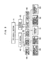
- Fig. 2 shows a block diagram of the main processor 5A and the sub-processor 6A of the service unit 3.
- the backup unit 4 is similarly configured.
- the main processor 5A comprises a CPU 11, a ROM 12, a RAM 13 and logic circuits 14 and 15 for controlling an interface to the sub-processor 6A.
- the logic circuit 14 is an interface for sending commands and data from the main processor 5A to the sub-processor 6A
- the logic circuit 15 is an interface for sending sub-processor status and data from the sub-processor 6A to the main processor 5A.
- the sub-processor such as floppy disk drive (FDD) or magnetic card reader (MCR) (not shown) may be connected to the CUP 11 of the main processor 5A in the same manner.
- the sub-processor 6A comprises a sub-CPU 18, a ROM 19, a RAM 20, an interface 16 for receiving commands and data from the main processor 5A, an interface 17 for sending status and data of the sub-processor 6A from the sub-processor 6A to the main processor 5A, a latch 23 for generating an enable signal indicating that the service unit is functioning as the master station, to the line switch 2, a latch 24 for holding the entire sub-processor 6A in a reset state, a transmitter 25 for converting a serial data from the sub-CPU 18 to an electrical signal on the data transmission line 8 and transmitting it, a receiver 26 for converting the signal on the data transmission line 8 to an internal signal, a NAND inverter 27 for inverting the output of the latch 24 to enable or disable the transmitter 25, a selection gate 28, and an impedance detector 29 to be described later.
- the input to the interfacre 16 is connected to the output of the interface 14 of the main processor 5A, and the output of the interface 17 is connected to the input of the interface 15 of the main processor 5A.
- the reset terminal of the latch 23 is connected to an output of an OR circuit 21.
- One input of the OR circuit 21 is connected to a signal line 31 extending from the main processor 5A and the other input is connected to an output line 36 of the latch 24.
- the signal of the main processor 5A is applied to a set terminal of the latch 23 through the line 34.
- the main processor 11 can set or reset the latch 23 by setting the signal lines 31 and 34 to logical levels "0" and "1".
- the output of the latch 23 is supplied to the signal line 7A in Fig. lA.
- the set terminal of the latch 24 is connected to the output of the OR circuit 22, and the inputs of the OR circuit are connected to the signal line 32 extending from the main processor 5A and the signal line 33 extending from the sub-CPU 18.
- the reset terminal of the latch 24 is connected to the signal line 35 extending from the main processor 5A.
- the main processor 5A can set and reset the latch 24.
- the output signal from the latch 24 is applied to the OR circuit 21 through the signal line 36, to the reset terminal of the sub-CPU 18 and to the NAND gate 27.
- the output of the NAND gate 27 is connected to the enable terminal of the transmitter 25.
- Fig. 3 shows a program structure of the main processor 5A. Necessary programs are stored in the ROM 12.
- An OS (operating system) kernel section 41 controls the overall processor. Under the program module, an I/O control section 42 and a system control section 43 are operated.
- the I/O control section 42 controls I/O devices.
- a communication control section 44 to the central processing unit 1, a master station control unit 45 for controlling data transmission with terminals and a slave station control section 46 such as control section for FDD and MCR operate under the I/O control section 42.
- the system control section 43 controls tasks of an application processing section 48 and processes input/output requests of the application processing section 48 through an I/O start control section 47.
- the master station control section 45 and the slave station control section 46 have communication processing section 49 with the application processing section 48, recovery processing section 50, command issuing section 51 for the sub-processor 6A, interrupt processing section 52 for interruption from the sub-processor 6A, and transmission/reception control section 53.
- the recovery processing section 50 also has a function to control freezing of the sub-processor 6A.
- the interrupt processing section 52 reads, checks and analyzes the status of sub-processor 6A.
- the transmission/reception control section 53 has a function to transmit and receive data and a function to process a data link level.
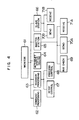
- Fig. 4 shows a program structure of the sub-processor 6A. Necessary programs are stored in the ROM 19.
- a monitor section 61 starts program modules, a command processing section 62 for a command from the main processor 54, an interrupt status issuing section 64 for the main processor 5A, a recovery processing section 63, a master station function control section 65 and a slave station function control unit 66, and processes end codes prepared by the program modules.
- the command processing section 62 reads a command issued by the main processor 5A to the sub-processor 6A and checks it by a timer monitor method.
- the interrupt status issuing section 64 reports processed results of other modules to the main processor 5A.
- the recovery processing section 63 controls retry to errors generated during data processing by the sub-processor and controls self-freezing.
- the master station function control section 65 is started when the sub-processor operates as the master station to start lower-order program modules, a bus check section 69 for detecting presence or absence of data transmission, a polling signal send control section 70A and a receive control section 71A.
- the slave station function control section 66 is started when the sub-processor operates as the slave station and the unit is operated as the backup unit for the master station. Under the module 66, there are a send control section 70B for responding to the polling, and a receive control section 71 for monitoring the polling.
- the send/receive control sections 70A, 70B, 71A and 71B control input/output processing at a physical level of data and procedures of data link level.
- Fig. 5A shows a transmission/reception data table used for an interface between the main processor 5A and the sub-processor 6A
- Fig. 5B shows a command format for illustrating types of commands delivered from the main processor 5A to the sub-processor 6A
- Fig. 5C shows a status format illustrating the contents of an interrupt status delivered from the sub-processor 6A to the main processor 5A.
- the transmission data table of Fig. 5A includes fields in a frame, address field, command field and information field.
- the information field is of up to 512-byte length and a transmitted data is of up to 514-byte length including the address, command and information fields.
- a minimum length is 2-byte length, that is, only the address command field.
- the 5B includes an initialization field to designate whether the sub-processor is to operate as a service unit or a backup unit (slave station), a test field to check validity of a hardware of the sub-processor 6A, a logging report field to report a record of the operation of the sub-processor 6 to the main processor 5A, a bus check field for checking data transmission status of the data transmission line, and transmission and reception fields to transmit and receive data.
- the meaning of the bits of the interrupt status is shown in Fig. 5C. When the transmission error bit and the reception error bit are at a logical level "1", detailed information of the error is accompanied although it is omitted in the present embodiment.
- the test command includes a sub-command to indicate a type of test, although it is omitted in the present embodiment.
- the service unit 3 in Fig. 1A starts the master station control section 45 of Fig. 3.
- the master station control unit 45 starts the transmission operation in accordance with the flow chart of Fig. 6.
- the communication processing section 49 for the application processing section 48 receives data prepared by the application processing section 48
- the transmission/reception control section 53 prepares the slave station address and command field at the link level, and sets the transmission data length into the transmission data table (Fig. 5A).
- the data table is prepared in the RAM 13 and set into the interface 14 to the sub-processor 6A.
- the command issuing section 51 sets the command "send" into the interface 14.
- the interrupt processing section 52 monitors the interruption from the sub-processor 6A in a timer monitor method as shown by blocks 103 - 107.
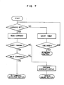
- the sub-processor 6A reads the command in accordance with the flow chart of Fig. 7, checks parity and validity of the command, and if they are normal, checks the content of the command and starts the master station function control section 65.
- the function control section 65 recognizes that the command is "send", it starts a send routine 70. As shown in Fig.
- the send routine 70 first reads the transmission data table prepared by the main processor 5A through the interface 16, secondly checks if the transmission data length is between 2 bytes and 514 bytes, thirdly checks the validity of the address field, fourthly checks the validity of the command field, and if they are normal, sends the data to the slave station through the transmitter 25 and the data transmission line 8.
- the transmission data length is 714 bytes due to an error in the interface 16.
- a transmission data length error is detected by the data length check routine shown in Fig. 8, an end code indicating the transmission data length error is generated, and the process returns from the transmission routine 70 to the master station function control section 65.
- the master station function control section 65 detects the end code of the transmission error, the process returns to the monitor section 61.
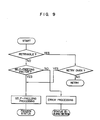
- the monitor section 61 starts the recovery processing section 63 to perform the recovery processing in accordance with a flow chart of Fig. 9.
- the transmission data length error is a retryable error factor. It is assumed that the same error consecutively occurs and the number of times of retry is exceeded.
- the recovery processing section 63 judges that it is an unrecoverable (uncorrectable) error and starts the freezing control section 68.
- the freezing control section 68 sets the signal line 33 of Fig. 2 to a logical level "1" by the I/O command to set the latch 24.
- the output signal line 36 of the latch 24 is set to a logical level "1”
- the sub-CPU 18 is reset and the transmitter 25 is disabled through the inverter 27.
- the sub-processor 6A is electrically disconnected from the data transmission bus line 8.
- the signal line 36 is set to a logical level "1”
- the latch 23 which indicates the master station is reset and the signal line 7 is reset to a logical level "0" so that the service unit 3 is disconnected from the central processing unit 1.
- the main processor 5A starts the recovery processing section 50 to perform the freezing processing of the sub-processor 6A, and resets the latch 23 and sets the latch 24 through the signal lines 31 and 32. At this time, the latch 23 has been reset and the latch 24 has been set by the self-freezing operation of the sub-processor 6A.
- the backup unit is usually started as a slave station as shown in Fig. 10.
- the backup unit 4 monitors the polling to its own unit under the data transmission control from the service unit 3 which is the master station.
- the sub-processor 6B of the backup unit 4 detects the polling error and reports it to the main processor 5B as a kind of reception error.
- the main processor 5B receives the polling error report, it starts the master station control section 45 of Fig. 3.
- the master station control section 45 reinitializes the sub-processor 6B as a master station.
- the main processor 5B issues a command "test" to check the validity of the elements of the sub-processor 6B.
- the test may include a CRC (cycle redundancy check) test for the ROM 19, a write/read test for the RAM 20, and a self-loop test in which transmission data is simultaneously received and the transmission data and the reception data are compared.
- the self-loop test includes an internal self-loop test in which a selector 28 selects an input to the transmitter 25 as the reception data, and an external self-loop test in which the selector 28 selects an output of the receiver 26. In the external self-loop test, since the data is sent to the data transmission bus line 8, only the station which operates as the master station executes such a test during a period between successive transmissions of polling signals.
- the main processor 5B issues a command "check bus" to check presence or absence of the data transmission on the data transmission bus line 8 to determine that the service unit 3 is not carrying out the data transmission control operation.
- the method to check the presence or absence of thedata transmission includes a method for detecting a data transmission carrier, which is conventionally known, and a method for detecting an impedance on the data transmission line. In the present embodiment, the data status is checked by program-scanning the impedance.
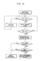
- Fig. 11 shows an embodiment of an impedance detector 29, and Fig.
- FIG. 12 shows a program structure for scanning the output of the impedance detector 29 and measuring durations of low impedance or high impedance (disconnection) status.
- a low impedance (LZ) counter shown in Fig. 12 measures the duration of the low impedance.
- the sub-processor 6B checks the impedance on the data transmission bus line 8 in accordance with the flow chart in Fig. 12 and reports the absence of the data transmission to the main processor 5B by the content of the interrupt status.
- the main processor 5B sets the signal line 34 to a logical level "1" by the output command to set the latch 23 which indicates the master station and start the communication with the central processing unit 1.
- the main processor 5B commands the transmission of the polling data to the sub-processor 6B and starts the data transmission control service as the master station.
- the present invention can be applied to a multi-computer system which has a plurality of service units and at least one backup unit.
- a task of the system is shared and each service unit performs the shared task. If one of the service units is down, a backup unit will replace the shared task of the service unit.
- Each service unit sends a polling signal with a number of identification which is uniquely assigned, while it is in the valid state.
- the backup unit monitors the polling signals from the service units as to whether they come during each predetermined time period or not. When one of the service unit is down or faulty, the processor thereof is frozen into a disable state in accordance with the scheme of the present invention.
- the backup unit detects which service unit is down in response to the number sent with the polling signal, and then replaces the data processing function of the fault service unit in accordance with the scheme of the present invention.
- a plurality of elemental processors constituting the service unit such as the main processor and the sub-processor are mutually monitored so that when the service unit is down, the sub-processor connecting the data bus line is frozen into a disable state and the service unit is thereby electrically or physically disconnected from the data bus line.
- the backup unit detects the error in the response from the service unit through the data bus line and checks the validity of the backup unit itself by the self-check, and then replaces the data processing function of the service unit.
Abstract
Description
- The present invention relates to method and apparatus for backing up a master station of a data transmission system having the master station and a slave station, and more particularly to method and apparatus for preventing an overrun when a failure occurs in the master station or service unit in a POS (point of sales) system or computer network systems.
- In a data transmission system, it is usual to connect a service unit (master station) and a backup unit to a data transmission line in common to terminals (slave station) and use the backup unit when the service unit is down, in order to enhance reliability. In a prior art system of this type such as a daisy chain type disclosed in JP-A-57-81655 laid open on May 21, 1982, a signal line for controlling switching between the service unit and the backup units, in addition to the data transmission line, is connected between the service unit and the backup units, and an inhibit signal is supplied to the signal line to switch the service unit and the backup unit. In this system, each backup unit requires the signal line and a logic unit to control it. Namely, the prior art system needs a number of signal lines and logic units having complex logic functions such as distinguishment between down state of the service unit and power-off state. This is a cause of cost increase. Further, because of a noise on the signal line, the logic unit may cause malfuntion. Because it is not possible to prevent an overrun signal due to a failure of the service unit from being transmitted to the data transmission line, the reliability to the backup operation is not sufficient and the influence of overrun to the slave station cannot be crucially prevented.
- It is an object to the present invention to provide method and apparatus for switching between a service unit and a backup unit in a data transmission system having the service unit and the backup unit, without requiring an additional or dedicated signal line.
- It is another object of the present invention to provide method and apparatus for backing up a data transmission system when a service unit is down, without disturbing other units or causing malfunction.
- It is other object of the present invention to provide method and apparatus for backing up data transmission system to enhance reliability of start of backup operation based on combination of detections of different factors representing failures of a service unit.
- In accordance with a feature of the present invention, a service unit, a backup unit and at least one slave station are connected to a data transmission line, and the service unit and the backup unit each comprises a main processor for controlling itself and at least one sub-processor for performing a specific processing such as line controlling or file processing. Based on empirical facts that a possibility of occurrence of failures simultaneously at two or more of the main processor, sub-processor and junction of the main processor and sub-processor is very small, the operations thereof are mutually monitored by the main processor and the sub-processor and if a failure is detected, the data transmission control operation is frozen so that influence to other units such as lines service unit or slave station by an error data signal or an overrun signal is prevented.
- In the present invention, means to monitor the operation of other unit is provided in each of the main processor and the sub-processor, and when a failure is detected, the data transmission control operation of the service unit is frozen or disabled so that the failure service unit is electrically or physically disconnected from the data transmission line. On the other hand, the backup unit can detect the freezing or disabling of the data transmission control operation by the service unit by detecting abnormality or error indication factors such as polling error, line impedance abnormal or absence of token through the conventional data transmission line. When the backup unit detects the failure in the data transmission control operation of the service station, it tests the validity of the data transmission control operation of its own unit and then immediately starts the backup operation to the service unit.
-
- Fig. 1A is a block diagram showing a service unit/backup unit switching system in accordance with an embodiment of the present invention.
- Fig. 1B is a timing diagram for explaining a backup operation between the service unit, the backup unit and a data transmission line in the configuration shown in Fig. 1A.
- Fig. 2 is a block diagram showing the configuration of a main processor and a sub-processor of the service unit and the backup unit.
- Figs. 3 and 4 show program structures of a main processor and a sub-processor, respectively.
- Figs. 5A, 5B and 5C show a data table of interface information of the main processor and the sub-processor, and formats thereof, respectively.
- Fig. 6 shows a transmission flow chart of the main processor.
- Fig. 7 shows a command flow chart of the sub-processor.
- Fig. 8 shows a transmission flow chart of the sub-processor.
- Fig. 9 shows a recovery processing flow chart of the sub-processor.
- Fig. 10 shows a processing flow chart of the backup unit.
- Fig. 11 shows a circuit configuration of an impedance detector.
- Fig. 12 shows a flow chart of an impedance check program.
- In order to facilitate the understanding of the present invention, an embodiment of the present invention applied to a POS system is explained, although it should be understood that the present invention is applicable to a multi-computer system.
- Fig. lA shows a configuration of a data transmission system in accordance with an embodiment of the present invention. A central processing unit 1 is located in a head office of the POS system and performs collective data processings to branch offices. It is selectively connected by a
line switch 2 to aservice unit 3 or abackup unit 4 located in each bracnh office. The central processing unit 1 is not essential to the present invention. Theservice unit 3 comprises amain processor 5A and at least onesub-processor 6A, and thebackup unit 4 comprises at least the same elements (circuits) as theservice unit 3, that is, amain processor 5B and asub-processor 6B. Theunits sub-processor 6A of theservice unit 3 serving as a master station controls data transmissions between the master station and a plurality ofslave stations 9 connected thereto by adata transmission line 8. The slave stations are usually cash/card registers. Thetransmission line 8 may be in-line or local area network. While theservice unit 3 operates normally, thesub-processor 6B of thebackup unit 4 functions as the slave station and monitors whether a polling signal is sent from the master station (branch office) during a predetermined time interval or not. When asignal line service unit 3 operates normally, thesignal line 7A is at a locial level "1" and thesignal line 7B is at a logical level "0". The central processing unit 1 is connected to theunit signal line - Fig. 1B shows a relationship between a mutual monitor time of the
main processor 5A and thesub-processor 6A and a monitor time for polling from theservice unit 3 by thebackup unit 4 and theslave station 9. The mutual monitor time (for example, six seconds) of themain processor 5A and thesub-processor 6A is shorter than the monitor time for the polling from theservice unit 3 by the backup unit 4 (for example, 15 seconds). The monitor time for the polling from theservice unit 3 by theslave station 9 is further longer (for example, 30 seconds). - After the
backup unit 4 has detected an error or abnormality in the polling from theservice unit 4 and before theslave station 9 detects the error in the polling from the service unit to switch to the off-line mode, the backup unit completes the switching to the service unit operation and starts the line service. - Preparation for the switching to the service unit operation includes loading of a service unit program to a main memory, internal self-check and checking of presence or absence of data transmission. The program is stored in e.g. a magnetic disk unit (not shown) connected to the system.
- Fig. 2 shows a block diagram of the
main processor 5A and thesub-processor 6A of theservice unit 3. Thebackup unit 4 is similarly configured. - The
main processor 5A comprises a CPU 11, aROM 12, aRAM 13 andlogic circuits sub-processor 6A. Thelogic circuit 14 is an interface for sending commands and data from themain processor 5A to thesub-processor 6A, and thelogic circuit 15 is an interface for sending sub-processor status and data from thesub-processor 6A to themain processor 5A. The sub-processor such as floppy disk drive (FDD) or magnetic card reader (MCR) (not shown) may be connected to the CUP 11 of themain processor 5A in the same manner. - The
sub-processor 6A comprises asub-CPU 18, aROM 19, aRAM 20, aninterface 16 for receiving commands and data from themain processor 5A, aninterface 17 for sending status and data of thesub-processor 6A from thesub-processor 6A to themain processor 5A, alatch 23 for generating an enable signal indicating that the service unit is functioning as the master station, to theline switch 2, alatch 24 for holding theentire sub-processor 6A in a reset state, atransmitter 25 for converting a serial data from thesub-CPU 18 to an electrical signal on thedata transmission line 8 and transmitting it, areceiver 26 for converting the signal on thedata transmission line 8 to an internal signal, aNAND inverter 27 for inverting the output of thelatch 24 to enable or disable thetransmitter 25, aselection gate 28, and animpedance detector 29 to be described later. The input to theinterfacre 16 is connected to the output of theinterface 14 of themain processor 5A, and the output of theinterface 17 is connected to the input of theinterface 15 of themain processor 5A. The reset terminal of thelatch 23 is connected to an output of anOR circuit 21. One input of theOR circuit 21 is connected to asignal line 31 extending from themain processor 5A and the other input is connected to anoutput line 36 of thelatch 24. The signal of themain processor 5A is applied to a set terminal of thelatch 23 through theline 34. The main processor 11 can set or reset thelatch 23 by setting thesignal lines latch 23 is supplied to thesignal line 7A in Fig. lA. - The set terminal of the
latch 24 is connected to the output of theOR circuit 22, and the inputs of the OR circuit are connected to thesignal line 32 extending from themain processor 5A and the signal line 33 extending from the sub-CPU 18. The reset terminal of thelatch 24 is connected to thesignal line 35 extending from themain processor 5A. Themain processor 5A can set and reset thelatch 24. The output signal from thelatch 24 is applied to theOR circuit 21 through thesignal line 36, to the reset terminal of the sub-CPU 18 and to theNAND gate 27. The output of theNAND gate 27 is connected to the enable terminal of thetransmitter 25. - Fig. 3 shows a program structure of the
main processor 5A. Necessary programs are stored in theROM 12. An OS (operating system)kernel section 41 controls the overall processor. Under the program module, an I/O control section 42 and asystem control section 43 are operated. The I/O control section 42 controls I/O devices. Acommunication control section 44 to the central processing unit 1, a master station control unit 45 for controlling data transmission with terminals and a slavestation control section 46 such as control section for FDD and MCR operate under the I/O control section 42. Thesystem control section 43 controls tasks of anapplication processing section 48 and processes input/output requests of theapplication processing section 48 through an I/Ostart control section 47. The master station control section 45 and the slavestation control section 46 havecommunication processing section 49 with theapplication processing section 48,recovery processing section 50,command issuing section 51 for the sub-processor 6A, interrupt processing section 52 for interruption from the sub-processor 6A, and transmission/reception control section 53. Therecovery processing section 50 also has a function to control freezing of the sub-processor 6A. The interrupt processing section 52 reads, checks and analyzes the status of sub-processor 6A. The transmission/reception control section 53 has a function to transmit and receive data and a function to process a data link level. - Fig. 4 shows a program structure of the sub-processor 6A. Necessary programs are stored in the
ROM 19. Amonitor section 61 starts program modules, acommand processing section 62 for a command from the main processor 54, an interruptstatus issuing section 64 for themain processor 5A, arecovery processing section 63, a master stationfunction control section 65 and a slave stationfunction control unit 66, and processes end codes prepared by the program modules. Thecommand processing section 62 reads a command issued by themain processor 5A to the sub-processor 6A and checks it by a timer monitor method. The interruptstatus issuing section 64 reports processed results of other modules to themain processor 5A. Therecovery processing section 63 controls retry to errors generated during data processing by the sub-processor and controls self-freezing. The master stationfunction control section 65 is started when the sub-processor operates as the master station to start lower-order program modules, abus check section 69 for detecting presence or absence of data transmission, a polling signal sendcontrol section 70A and a receive control section 71A. The slave stationfunction control section 66 is started when the sub-processor operates as the slave station and the unit is operated as the backup unit for the master station. Under themodule 66, there are asend control section 70B for responding to the polling, and a receive control section 71 for monitoring the polling. The send/receivecontrol sections - Fig. 5A shows a transmission/reception data table used for an interface between the
main processor 5A and the sub-processor 6A, Fig. 5B shows a command format for illustrating types of commands delivered from themain processor 5A to the sub-processor 6A, and Fig. 5C shows a status format illustrating the contents of an interrupt status delivered from the sub-processor 6A to themain processor 5A. - When the HDLC (high level data link control) of the CCITT Standard is used as the data link level procedure in the present embodiment, the transmission data table of Fig. 5A includes fields in a frame, address field, command field and information field. In the present embodiment, the information field is of up to 512-byte length and a transmitted data is of up to 514-byte length including the address, command and information fields. A minimum length is 2-byte length, that is, only the address command field. The command shown in Fig. 5B includes an initialization field to designate whether the sub-processor is to operate as a service unit or a backup unit (slave station), a test field to check validity of a hardware of the sub-processor 6A, a logging report field to report a record of the operation of the sub-processor 6 to the
main processor 5A, a bus check field for checking data transmission status of the data transmission line, and transmission and reception fields to transmit and receive data. The meaning of the bits of the interrupt status is shown in Fig. 5C. When the transmission error bit and the reception error bit are at a logical level "1", detailed information of the error is accompanied although it is omitted in the present embodiment. The test command includes a sub-command to indicate a type of test, although it is omitted in the present embodiment. - The backup operation for the
service unit 3 and thebackup unit 4 is explained with reference to flow charts of Figs. 6 to 10. - The
service unit 3 in Fig. 1A starts the master station control section 45 of Fig. 3. In themain processor 5A, when theapplication processing section 48 requests data transmission to theslave station 9, the master station control unit 45 starts the transmission operation in accordance with the flow chart of Fig. 6. When thecommunication processing section 49 for theapplication processing section 48 receives data prepared by theapplication processing section 48, the transmission/reception control section 53 prepares the slave station address and command field at the link level, and sets the transmission data length into the transmission data table (Fig. 5A). The data table is prepared in theRAM 13 and set into theinterface 14 to the sub-processor 6A. Then, thecommand issuing section 51 sets the command "send" into theinterface 14. Thereafter, the interrupt processing section 52 monitors the interruption from the sub-processor 6A in a timer monitor method as shown by blocks 103 - 107. - When the command processing section recognizes through the
interface 16 to themain processor 5A that themain processor 5A has set the command, the sub-processor 6A reads the command in accordance with the flow chart of Fig. 7, checks parity and validity of the command, and if they are normal, checks the content of the command and starts the master stationfunction control section 65. When thefunction control section 65 recognizes that the command is "send", it starts a send routine 70. As shown in Fig. 8, the send routine 70 first reads the transmission data table prepared by themain processor 5A through theinterface 16, secondly checks if the transmission data length is between 2 bytes and 514 bytes, thirdly checks the validity of the address field, fourthly checks the validity of the command field, and if they are normal, sends the data to the slave station through thetransmitter 25 and thedata transmission line 8. - Let us assume that the transmission data length is 714 bytes due to an error in the
interface 16. Thus, a transmission data length error is detected by the data length check routine shown in Fig. 8, an end code indicating the transmission data length error is generated, and the process returns from the transmission routine 70 to the master stationfunction control section 65. When the master stationfunction control section 65 detects the end code of the transmission error, the process returns to themonitor section 61. Themonitor section 61 starts therecovery processing section 63 to perform the recovery processing in accordance with a flow chart of Fig. 9. The transmission data length error is a retryable error factor. It is assumed that the same error consecutively occurs and the number of times of retry is exceeded. Therecovery processing section 63 then judges that it is an unrecoverable (uncorrectable) error and starts the freezingcontrol section 68. The freezingcontrol section 68 sets the signal line 33 of Fig. 2 to a logical level "1" by the I/O command to set thelatch 24. As theoutput signal line 36 of thelatch 24 is set to a logical level "1", the sub-CPU 18 is reset and thetransmitter 25 is disabled through theinverter 27. Thus, the sub-processor 6A is electrically disconnected from the datatransmission bus line 8. As thesignal line 36 is set to a logical level "1", thelatch 23 which indicates the master station is reset and the signal line 7 is reset to a logical level "0" so that theservice unit 3 is disconnected from the central processing unit 1. - If there is no interruption request from the sub-processor 6A for more than a predetermined time period, the
main processor 5A starts therecovery processing section 50 to perform the freezing processing of the sub-processor 6A, and resets thelatch 23 and sets thelatch 24 through thesignal lines latch 23 has been reset and thelatch 24 has been set by the self-freezing operation of the sub-processor 6A. - The backup unit is usually started as a slave station as shown in Fig. 10. As slave
station control section 46 of Fig. 3 and the slave stationfunction control unit 66 of Fig. 4 are started, thebackup unit 4 monitors the polling to its own unit under the data transmission control from theservice unit 3 which is the master station. As theservice unit 3 ceases the data transmission control operation, the sub-processor 6B of thebackup unit 4 detects the polling error and reports it to themain processor 5B as a kind of reception error. When themain processor 5B receives the polling error report, it starts the master station control section 45 of Fig. 3. The master station control section 45 reinitializes the sub-processor 6B as a master station. Then themain processor 5B issues a command "test" to check the validity of the elements of the sub-processor 6B. The test may include a CRC (cycle redundancy check) test for theROM 19, a write/read test for theRAM 20, and a self-loop test in which transmission data is simultaneously received and the transmission data and the reception data are compared. The self-loop test includes an internal self-loop test in which aselector 28 selects an input to thetransmitter 25 as the reception data, and an external self-loop test in which theselector 28 selects an output of thereceiver 26. In the external self-loop test, since the data is sent to the datatransmission bus line 8, only the station which operates as the master station executes such a test during a period between successive transmissions of polling signals. - If the validity is determined through the internal self-loop test in any appropriate time such as power-on time, the
main processor 5B issues a command "check bus" to check presence or absence of the data transmission on the datatransmission bus line 8 to determine that theservice unit 3 is not carrying out the data transmission control operation. The method to check the presence or absence of thedata transmission includes a method for detecting a data transmission carrier, which is conventionally known, and a method for detecting an impedance on the data transmission line. In the present embodiment, the data status is checked by program-scanning the impedance. Fig. 11 shows an embodiment of animpedance detector 29, and Fig. 12 shows a program structure for scanning the output of theimpedance detector 29 and measuring durations of low impedance or high impedance (disconnection) status. A low impedance (LZ) counter shown in Fig. 12 measures the duration of the low impedance. - The sub-processor 6B checks the impedance on the data
transmission bus line 8 in accordance with the flow chart in Fig. 12 and reports the absence of the data transmission to themain processor 5B by the content of the interrupt status. Themain processor 5B then sets thesignal line 34 to a logical level "1" by the output command to set thelatch 23 which indicates the master station and start the communication with the central processing unit 1. Themain processor 5B commands the transmission of the polling data to the sub-processor 6B and starts the data transmission control service as the master station. - The present invention can be applied to a multi-computer system which has a plurality of service units and at least one backup unit. In this kind of system, for example, a task of the system is shared and each service unit performs the shared task. If one of the service units is down, a backup unit will replace the shared task of the service unit. Each service unit sends a polling signal with a number of identification which is uniquely assigned, while it is in the valid state. The backup unit monitors the polling signals from the service units as to whether they come during each predetermined time period or not. When one of the service unit is down or faulty, the processor thereof is frozen into a disable state in accordance with the scheme of the present invention. The backup unit detects which service unit is down in response to the number sent with the polling signal, and then replaces the data processing function of the fault service unit in accordance with the scheme of the present invention.
- In accordance with the present invention described above, a plurality of elemental processors constituting the service unit, such as the main processor and the sub-processor are mutually monitored so that when the service unit is down, the sub-processor connecting the data bus line is frozen into a disable state and the service unit is thereby electrically or physically disconnected from the data bus line. Thus, the backup unit detects the error in the response from the service unit through the data bus line and checks the validity of the backup unit itself by the self-check, and then replaces the data processing function of the service unit. Accordingly, an overrun or disturbance caused due to failure of the service unit is essentially prevented, no dedicated signal line is required between the backup unit and the service unit to switch between the service unit and the backup unit, even when the backup operation is implemented in a daisy chain and the cost of the service/backup unit switching system is reduced and the error due to the control of the service/backup unit switching signal line is eliminated.
Claims (17)
said service unit including:
a main processor (5A, 5B) for controlling the entire unit;
at least one sub-processor (6A, 6B) for performing a specific processing;
error detection means (12, 19; 11, 18) located in said main processor and said sub-processor for mutually monitor the validity of the operation of other unit to detect an error in the unit; and
disconnection means (22, 24, 27, 25) for disconnecting said service unit from said data transmission line in response to the output of said error detection means;
said backup unit further including:
backup start means (26, 29, 11-13) for detecting the disconnection of said system service unit through the data transmission line to start said backup unit.
said master unit and said backup unit each comprising a plurality of processor blocks (5A, 6A; 5B, 6B0 and disabling means (27, 25, 36) for disabling its own unit;
said processor blocks each including error detection means (11, 12; 18, 19) for mutually monitoring validity and normality of operations of other processor blocks to detect any errors;
said disabling means freezing the data transmission control operation of its own unit in responce to the output of said error detection means and disconnecting its own unit from said data transmission line; and
said backup unit further comprising means (29, 26, 11, 12) for detecting the frozen status of the operation of said master unit based on the status of said data transmission line and signals therefrom and starting said backup unit in response to the detected output.
Applications Claiming Priority (2)
| Application Number | Priority Date | Filing Date | Title |
|---|---|---|---|
| JP211929/85 | 1985-09-25 | ||
| JP60211929A JPS6272248A (en) | 1985-09-25 | 1985-09-25 | Active/standby changeover method for data transmission system |
Publications (3)
| Publication Number | Publication Date |
|---|---|
| EP0216353A2 true EP0216353A2 (en) | 1987-04-01 |
| EP0216353A3 EP0216353A3 (en) | 1988-11-09 |
| EP0216353B1 EP0216353B1 (en) | 1993-02-17 |
Family
ID=16614011
Family Applications (1)
| Application Number | Title | Priority Date | Filing Date |
|---|---|---|---|
| EP86113078A Expired - Lifetime EP0216353B1 (en) | 1985-09-25 | 1986-09-23 | Method and apparatus for backing up data transmission system |
Country Status (4)
| Country | Link |
|---|---|
| US (1) | US4775976A (en) |
| EP (1) | EP0216353B1 (en) |
| JP (1) | JPS6272248A (en) |
| DE (1) | DE3687777T2 (en) |
Cited By (6)
| Publication number | Priority date | Publication date | Assignee | Title |
|---|---|---|---|---|
| DE3736550A1 (en) * | 1986-10-28 | 1988-05-11 | Hitachi Ltd | METHOD AND DEVICE FOR SIMULTANEOUS DATA TRAFFIC |
| FR2630558A1 (en) * | 1988-04-20 | 1989-10-27 | Binh Paul | Terminal for data processing |
| GB2228114A (en) * | 1989-02-13 | 1990-08-15 | Westinghouse Brake & Signal | Processor testing system |
| EP0470880A1 (en) * | 1990-08-09 | 1992-02-12 | Bull S.A. | Apparatus for service processor dynamic swapping |
| US5774642A (en) * | 1990-08-09 | 1998-06-30 | Bull S.A. | Architecture for dynamic service processor exchange providing multitasking environment where multiple processors have access to a system configuration table |
| EP0760503B1 (en) * | 1995-06-19 | 2001-08-22 | Compaq Computer Corporation | Fault tolerant multiple network servers |
Families Citing this family (55)
| Publication number | Priority date | Publication date | Assignee | Title |
|---|---|---|---|---|
| US5317715A (en) * | 1987-12-15 | 1994-05-31 | Advanced Micro Devices, Inc. | Reduced instruction set computer system including apparatus and method for coupling a high performance RISC interface to a peripheral bus having different performance characteristics |
| US4879716A (en) * | 1987-12-23 | 1989-11-07 | Bull Hn Information Systems Inc. | Resilient data communications system |
| US5247692A (en) * | 1988-02-08 | 1993-09-21 | Nec Corporation | Multiple file system having a plurality of file units holding the same files in which loss of data is prevented in a failure of a file unit |
| JPH0783366B2 (en) * | 1988-03-15 | 1995-09-06 | 富士通株式会社 | Building management system |
| JPH0271644A (en) * | 1988-09-07 | 1990-03-12 | Toshiba Corp | Master slave type control system |
| JPH0814797B2 (en) * | 1988-11-14 | 1996-02-14 | 日本電気株式会社 | Checking method in redundant processing equipment |
| JP2755437B2 (en) * | 1989-07-20 | 1998-05-20 | 富士通株式会社 | Continuous operation guarantee processing method of communication control program |
| US5008805A (en) * | 1989-08-03 | 1991-04-16 | International Business Machines Corporation | Real time, fail safe process control system and method |
| DE645685T1 (en) * | 1989-08-31 | 1995-11-09 | Yokogawa Electric Corp | Method for controlling a line computer for executing and relocating a translated program from a data storage collection. |
| JPH03164837A (en) * | 1989-11-22 | 1991-07-16 | Hitachi Ltd | Spare switching system for communication control processor |
| WO1991008535A1 (en) * | 1989-11-27 | 1991-06-13 | Olin Corporation | Method and apparatus for providing backup process control |
| US5038368A (en) * | 1990-02-02 | 1991-08-06 | David Sarnoff Research Center, Inc. | Redundancy control circuit employed with various digital logic systems including shift registers |
| JP2560510B2 (en) * | 1990-03-06 | 1996-12-04 | 日本電気株式会社 | Network management manager switching method |
| US5195040A (en) * | 1990-03-19 | 1993-03-16 | The United States Of America As Represented By The Secretary Of The Navy | Backup navigation system |
| US5126730A (en) * | 1990-03-30 | 1992-06-30 | At&T Bell Laboratories | Multipoint TBOS interface including backup response unit |
| US5271013A (en) * | 1990-05-09 | 1993-12-14 | Unisys Corporation | Fault tolerant computer system |
| US5187706A (en) * | 1990-10-30 | 1993-02-16 | At&T Bell Laboratories | Dual access rings for communications networks |
| US5289578A (en) * | 1990-11-09 | 1994-02-22 | Foreign Exchange Transaction Services, Inc. | Activation of a dormant sibling computer in a communication network by overriding a unique dormant node address with a common active node address |
| US5530949A (en) * | 1991-03-19 | 1996-06-25 | Fujitsu Limited | Transmission equipment |
| JPH0564077A (en) * | 1991-08-30 | 1993-03-12 | Sony Corp | Switcher |
| GB9121540D0 (en) * | 1991-10-10 | 1991-11-27 | Smiths Industries Plc | Computing systems and methods |
| US5815651A (en) * | 1991-10-17 | 1998-09-29 | Digital Equipment Corporation | Method and apparatus for CPU failure recovery in symmetric multi-processing systems |
| US5289179A (en) * | 1991-11-27 | 1994-02-22 | At&T Bell Laboratories | Maintaining stable virtual circuit data connections with spare protocol handler |
| US5530908A (en) * | 1992-06-26 | 1996-06-25 | Motorola, Inc. | Apparatus for providing fault tolerance in a radio communication system |
| US5408647A (en) * | 1992-10-02 | 1995-04-18 | Compaq Computer Corporation | Automatic logical CPU assignment of physical CPUs |
| US5351019A (en) * | 1992-12-15 | 1994-09-27 | Alcatel Network Systems, Inc. | Local area network interface and interfacing method for network element |
| JPH06205295A (en) * | 1992-12-28 | 1994-07-22 | Sony Corp | Video signal transmitter |
| US5448766A (en) * | 1993-05-10 | 1995-09-05 | Motorola, Inc. | Method and apparatus for automatically replacing a non-functioning transmitter in a radio communication system |
| US5566297A (en) * | 1994-06-16 | 1996-10-15 | International Business Machines Corporation | Non-disruptive recovery from file server failure in a highly available file system for clustered computing environments |
| DE4429278C2 (en) * | 1994-08-19 | 1996-09-12 | Siemens Ag | Functional unit |
| US5491792A (en) * | 1994-09-23 | 1996-02-13 | Forney International, Inc. | Sequence of events system using a redundant analog I/O board system |
| KR0133337B1 (en) * | 1994-12-21 | 1998-04-21 | 양승택 | Tarket system control |
| US5495569A (en) * | 1994-12-30 | 1996-02-27 | Compaq Computer Corp. | Circuit for ensuring that a local interrupt controller in a microprocessor is powered up active |
| US5627962A (en) * | 1994-12-30 | 1997-05-06 | Compaq Computer Corporation | Circuit for reassigning the power-on processor in a multiprocessing system |
| JP2735023B2 (en) * | 1995-03-30 | 1998-04-02 | 日本電気株式会社 | Data control system |
| US5917723A (en) * | 1995-05-22 | 1999-06-29 | Lsi Logic Corporation | Method and apparatus for transferring data between two devices with reduced microprocessor overhead |
| US5535191A (en) * | 1995-06-28 | 1996-07-09 | Seiko Communications Systems, Inc. | Method and apparatus for switching between redundant hardware in a wireless data communication system |
| JPH0923254A (en) * | 1995-07-05 | 1997-01-21 | Fujitsu Ltd | Inter-system data link system |
| JP3445435B2 (en) * | 1995-09-11 | 2003-09-08 | 株式会社東芝 | Control device and control method for continuous data server device |
| US5771343A (en) * | 1996-02-14 | 1998-06-23 | Sterling Commerce, Inc. | System and method for failure detection and recovery |
| US6073193A (en) * | 1997-04-24 | 2000-06-06 | Cypress Semiconductor Corp. | Fail safe method and apparatus for a USB device |
| US6275200B1 (en) * | 1997-12-17 | 2001-08-14 | Lacerta Enterprises, Inc. | Method and apparatus for a transparent network guest controller |
| JP2001229097A (en) * | 2000-02-18 | 2001-08-24 | Fujitsu Ltd | Distribution processing system and client |
| JP2002024141A (en) * | 2000-07-05 | 2002-01-25 | Nec Corp | Method, device and system for substituting translation of electronic mail |
| US7334006B1 (en) * | 2000-09-27 | 2008-02-19 | Microsoft Corporation | Off-line support for cumulative backups |
| US6992979B2 (en) * | 2001-02-07 | 2006-01-31 | Lucent Technologies Inc. | Maintaining information to optimize restorable dynamic routing with shared backup |
| US6918062B2 (en) * | 2001-09-28 | 2005-07-12 | Intel Corporation | System and method to implement a cost-effective remote system management mechanism using a serial communication controller and interrupts |
| US20040153700A1 (en) * | 2003-01-02 | 2004-08-05 | Nixon Mark J. | Redundant application stations for process control systems |
| US20040249585A1 (en) * | 2003-06-04 | 2004-12-09 | Barr Andrew H. | Apparatus and method for detecting high impedance failures in system interconnect |
| US7653123B1 (en) | 2004-09-24 | 2010-01-26 | Cypress Semiconductor Corporation | Dynamic data rate using multiplicative PN-codes |
| US7906982B1 (en) | 2006-02-28 | 2011-03-15 | Cypress Semiconductor Corporation | Interface apparatus and methods of testing integrated circuits using the same |
| WO2009063565A1 (en) * | 2007-11-16 | 2009-05-22 | Fujitsu Limited | Control system, control method, master device, and controller |
| US8522069B2 (en) * | 2010-01-21 | 2013-08-27 | Wincor Nixdorf International Gmbh | Process for secure backspacing to a first data center after failover through a second data center and a network architecture working accordingly |
| US10776233B2 (en) | 2011-10-28 | 2020-09-15 | Teradyne, Inc. | Programmable test instrument |
| US9759772B2 (en) | 2011-10-28 | 2017-09-12 | Teradyne, Inc. | Programmable test instrument |
Citations (3)
| Publication number | Priority date | Publication date | Assignee | Title |
|---|---|---|---|---|
| JPS5831440A (en) * | 1981-08-19 | 1983-02-24 | Fujitsu Ltd | Automatic switching system for remote communication control processing device |
| US4500951A (en) * | 1981-01-07 | 1985-02-19 | Hitachi, Ltd. | Plant control system |
| EP0139125A2 (en) * | 1983-09-12 | 1985-05-02 | International Business Machines Corporation | Computer system including a workstation takeover control apparatus |
Family Cites Families (3)
| Publication number | Priority date | Publication date | Assignee | Title |
|---|---|---|---|---|
| US4133027A (en) * | 1977-09-13 | 1979-01-02 | Honeywell Inc. | Process control system with backup process controller |
| US4521871A (en) * | 1982-04-12 | 1985-06-04 | Allen-Bradley Company | Programmable controller with back-up capability |
| US4623883A (en) * | 1984-12-10 | 1986-11-18 | Ncr Corporation | Automatic communications switch |
-
1985
- 1985-09-25 JP JP60211929A patent/JPS6272248A/en active Granted
-
1986
- 1986-09-23 EP EP86113078A patent/EP0216353B1/en not_active Expired - Lifetime
- 1986-09-23 DE DE8686113078T patent/DE3687777T2/en not_active Expired - Fee Related
- 1986-09-24 US US06/911,073 patent/US4775976A/en not_active Expired - Lifetime
Patent Citations (3)
| Publication number | Priority date | Publication date | Assignee | Title |
|---|---|---|---|---|
| US4500951A (en) * | 1981-01-07 | 1985-02-19 | Hitachi, Ltd. | Plant control system |
| JPS5831440A (en) * | 1981-08-19 | 1983-02-24 | Fujitsu Ltd | Automatic switching system for remote communication control processing device |
| EP0139125A2 (en) * | 1983-09-12 | 1985-05-02 | International Business Machines Corporation | Computer system including a workstation takeover control apparatus |
Non-Patent Citations (1)
| Title |
|---|
| PATENT ABSTRACTS OF JAPAN, vol. 7, no. 109 (P-196)[1254], 12th May 1983; & JP-A-58 031 440 (FUJITSU K.K.) 24-02-1983 * |
Cited By (11)
| Publication number | Priority date | Publication date | Assignee | Title |
|---|---|---|---|---|
| DE3736550A1 (en) * | 1986-10-28 | 1988-05-11 | Hitachi Ltd | METHOD AND DEVICE FOR SIMULTANEOUS DATA TRAFFIC |
| FR2630558A1 (en) * | 1988-04-20 | 1989-10-27 | Binh Paul | Terminal for data processing |
| GB2228114A (en) * | 1989-02-13 | 1990-08-15 | Westinghouse Brake & Signal | Processor testing system |
| GB2228114B (en) * | 1989-02-13 | 1993-02-10 | Westinghouse Brake & Signal | A system comprising a processor |
| AU634748B2 (en) * | 1989-02-13 | 1993-03-04 | Westinghouse Brake And Signal Holdings Limited | A system comprising a processor |
| US5504860A (en) * | 1989-02-13 | 1996-04-02 | Westinghouse Brake And Signal Holding Limited | System comprising a processor |
| EP0470880A1 (en) * | 1990-08-09 | 1992-02-12 | Bull S.A. | Apparatus for service processor dynamic swapping |
| FR2665778A1 (en) * | 1990-08-09 | 1992-02-14 | Bull Sa | ARCHITECTURE FOR DYNAMIC SERVICE PROCESSOR EXCHANGE. |
| WO1992002878A1 (en) * | 1990-08-09 | 1992-02-20 | Bull S.A. | Dynamic service processor exchange architecture |
| US5774642A (en) * | 1990-08-09 | 1998-06-30 | Bull S.A. | Architecture for dynamic service processor exchange providing multitasking environment where multiple processors have access to a system configuration table |
| EP0760503B1 (en) * | 1995-06-19 | 2001-08-22 | Compaq Computer Corporation | Fault tolerant multiple network servers |
Also Published As
| Publication number | Publication date |
|---|---|
| US4775976A (en) | 1988-10-04 |
| DE3687777T2 (en) | 1993-09-02 |
| DE3687777D1 (en) | 1993-03-25 |
| EP0216353B1 (en) | 1993-02-17 |
| JPH0560701B2 (en) | 1993-09-02 |
| EP0216353A3 (en) | 1988-11-09 |
| JPS6272248A (en) | 1987-04-02 |
Similar Documents
| Publication | Publication Date | Title |
|---|---|---|
| EP0216353B1 (en) | Method and apparatus for backing up data transmission system | |
| US4729124A (en) | Diagnostic system | |
| EP0147046B1 (en) | Fault-tolerant communications controlller system | |
| US5068851A (en) | Apparatus and method for documenting faults in computing modules | |
| EP0010211B1 (en) | Data storage subsystem comprising a pair of control units and method for the automatic recovery of data from a defaulting one of these control units | |
| US5086499A (en) | Computer network for real time control with automatic fault identification and by-pass | |
| CA2051786C (en) | Universal scheme of input/output redundancy in a process control system | |
| US4979108A (en) | Task synchronization arrangement and method for remote duplex processors | |
| US4890224A (en) | Method and apparatus for fault tolerant communication within a computing system | |
| US5644700A (en) | Method for operating redundant master I/O controllers | |
| JPH03131939A (en) | High-reliability computer diagnostic system | |
| JPH01293450A (en) | Troubled device specifying system | |
| EP0348704B1 (en) | Apparatus and method for simultaneously presenting error interrupt and error data to a support processor | |
| US4860289A (en) | Reset circuit for electrically isolated circuits communicating via uart | |
| US5742851A (en) | Information processing system having function to detect fault in external bus | |
| EP1999908B1 (en) | Apparatus for detecting errors in a communication system | |
| JP2827713B2 (en) | Redundant device | |
| JP3127941B2 (en) | Redundant device | |
| JP2521996B2 (en) | Communication system diagnostic method | |
| JP2001175545A (en) | Server system, fault diagnosing method, and recording medium | |
| CA1269141A (en) | Task synchronization arrangement and method for remote duplex processors | |
| KR930010950B1 (en) | Error-detecting device | |
| JP2825464B2 (en) | Communication device | |
| JPH0454747A (en) | Data transfer system | |
| EP0342261A1 (en) | Arrangement for error recovery in a self-guarding data processing system |
Legal Events
| Date | Code | Title | Description |
|---|---|---|---|
| PUAI | Public reference made under article 153(3) epc to a published international application that has entered the european phase |
Free format text: ORIGINAL CODE: 0009012 |
|
| AK | Designated contracting states |
Kind code of ref document: A2 Designated state(s): DE SE |
|
| PUAL | Search report despatched |
Free format text: ORIGINAL CODE: 0009013 |
|
| AK | Designated contracting states |
Kind code of ref document: A3 Designated state(s): DE SE |
|
| 17P | Request for examination filed |
Effective date: 19881110 |
|
| 17Q | First examination report despatched |
Effective date: 19910325 |
|
| GRAA | (expected) grant |
Free format text: ORIGINAL CODE: 0009210 |
|
| AK | Designated contracting states |
Kind code of ref document: B1 Designated state(s): DE SE |
|
| REF | Corresponds to: |
Ref document number: 3687777 Country of ref document: DE Date of ref document: 19930325 |
|
| PLBI | Opposition filed |
Free format text: ORIGINAL CODE: 0009260 |
|
| 26 | Opposition filed |
Opponent name: SIEMENS AG Effective date: 19931118 |
|
| EAL | Se: european patent in force in sweden |
Ref document number: 86113078.9 |
|
| PLBO | Opposition rejected |
Free format text: ORIGINAL CODE: EPIDOS REJO |
|
| PLBN | Opposition rejected |
Free format text: ORIGINAL CODE: 0009273 |
|
| STAA | Information on the status of an ep patent application or granted ep patent |
Free format text: STATUS: OPPOSITION REJECTED |
|
| 27O | Opposition rejected |
Effective date: 19960208 |
|
| PGFP | Annual fee paid to national office [announced via postgrant information from national office to epo] |
Ref country code: SE Payment date: 20010723 Year of fee payment: 16 |
|
| PGFP | Annual fee paid to national office [announced via postgrant information from national office to epo] |
Ref country code: DE Payment date: 20011129 Year of fee payment: 16 |
|
| PG25 | Lapsed in a contracting state [announced via postgrant information from national office to epo] |
Ref country code: SE Free format text: LAPSE BECAUSE OF NON-PAYMENT OF DUE FEES Effective date: 20020924 |
|
| PG25 | Lapsed in a contracting state [announced via postgrant information from national office to epo] |
Ref country code: DE Free format text: LAPSE BECAUSE OF NON-PAYMENT OF DUE FEES Effective date: 20030401 |
|
| EUG | Se: european patent has lapsed |