EP0216525B1 - A rotatable centrifugal fan blade assembly and air flow circulation apparatus - Google Patents
A rotatable centrifugal fan blade assembly and air flow circulation apparatus Download PDFInfo
- Publication number
- EP0216525B1 EP0216525B1 EP86306601A EP86306601A EP0216525B1 EP 0216525 B1 EP0216525 B1 EP 0216525B1 EP 86306601 A EP86306601 A EP 86306601A EP 86306601 A EP86306601 A EP 86306601A EP 0216525 B1 EP0216525 B1 EP 0216525B1
- Authority
- EP
- European Patent Office
- Prior art keywords
- disk
- rotor
- members
- air flow
- fan blade
- Prior art date
- Legal status (The legal status is an assumption and is not a legal conclusion. Google has not performed a legal analysis and makes no representation as to the accuracy of the status listed.)
- Expired - Lifetime
Links
- 230000000712 assembly Effects 0.000 description 4
- 238000000429 assembly Methods 0.000 description 4
- 230000001788 irregular Effects 0.000 description 2
- 230000007423 decrease Effects 0.000 description 1
- 230000001771 impaired effect Effects 0.000 description 1
- 238000012423 maintenance Methods 0.000 description 1
- 238000013341 scale-up Methods 0.000 description 1
Images

Classifications
-
- H—ELECTRICITY
- H05—ELECTRIC TECHNIQUES NOT OTHERWISE PROVIDED FOR
- H05K—PRINTED CIRCUITS; CASINGS OR CONSTRUCTIONAL DETAILS OF ELECTRIC APPARATUS; MANUFACTURE OF ASSEMBLAGES OF ELECTRICAL COMPONENTS
- H05K7/00—Constructional details common to different types of electric apparatus
- H05K7/20—Modifications to facilitate cooling, ventilating, or heating
- H05K7/20009—Modifications to facilitate cooling, ventilating, or heating using a gaseous coolant in electronic enclosures
- H05K7/20136—Forced ventilation, e.g. by fans
- H05K7/20172—Fan mounting or fan specifications
-
- F—MECHANICAL ENGINEERING; LIGHTING; HEATING; WEAPONS; BLASTING
- F04—POSITIVE - DISPLACEMENT MACHINES FOR LIQUIDS; PUMPS FOR LIQUIDS OR ELASTIC FLUIDS
- F04D—NON-POSITIVE-DISPLACEMENT PUMPS
- F04D29/00—Details, component parts, or accessories
- F04D29/26—Rotors specially for elastic fluids
- F04D29/28—Rotors specially for elastic fluids for centrifugal or helico-centrifugal pumps for radial-flow or helico-centrifugal pumps
- F04D29/281—Rotors specially for elastic fluids for centrifugal or helico-centrifugal pumps for radial-flow or helico-centrifugal pumps for fans or blowers
Landscapes
- Engineering & Computer Science (AREA)
- Microelectronics & Electronic Packaging (AREA)
- Physics & Mathematics (AREA)
- Thermal Sciences (AREA)
- Mechanical Engineering (AREA)
- General Engineering & Computer Science (AREA)
- Structures Of Non-Positive Displacement Pumps (AREA)
- Connection Of Motors, Electrical Generators, Mechanical Devices, And The Like (AREA)
- Motor Or Generator Cooling System (AREA)
Description
- This invention relates to rotatable centrifugal fan blade assemblies.
- US-A-4,385,333 discloses a rotatable centrifugal fan blade assembly comprising a substantially parallel circular rotor and disk member with a centrally disposed aperture and blade members disposed in a plane substantially normal to the plane of the rotor and the disk member.
- The movement of air into and out of housings of various units of equipment in use in the work place is done by the means of fans for the most part. As more and more machines are moved into the work place, the level of noise created by them increases substantially. Nevertheless, machines that are used in the modern office, including computer disk drives, must maintain adequate air flow for various purposes, in particular but not limited to maintenance of air pressure differentials and air flows. Accordingly the present invention seeks to provide rotatable centrifugal fan blade assemblies which are relatively quiet and produce an adequate air flow.
- According to one aspect of the present invention, there is provided a rotatable centrifugal fan blade assembly comprising: substantially parallel circular rotor and disk members at least one of which has a centrally disposed aperture (19), and a plurality of blade members each disposed in a plane substantially normal to the planes of said rotor and disk members, each blade member having leading and trailing edges, characterised in that at least one of the disk members has cut-outs each of which is located between the connection between two adjacent blade members in said at least one disk, and each of which is defined by a larger area disposed towards the trailing edge of one of said two blade members and by a smaller area disposed toward the leading edge of the other of said two blade members and in that the blade members extend between the rotor and the disk member.
- According to a further aspect of the present invention there is provided an air flow circulation apparatus comprising a centrifugal fan blade assembly in which only one of said disk members has a centrally disposed aperture and the second of said disk members comprises a rotor, the apparatus including a spindle member.
- In the preferred embodiment the air flow apparatus includes a magnetic media disk mounted on said spindle.
- The air flow apparatus may include an electrically conductive element between said rotor and said housing.
- The invention is illustrated, merely by way of example, in the accompanying drawings, in which:-
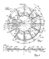
- Figure 1 shows a rotatable centrifugal fan blade assembly according to the present invention with one disk or plate removed and viewed from the side of the removed disk;
- Figure 2 is a side view of the fan blade assembly of Figure 1;
- Figure 3 is a cut-away portion of a disk of a fan blade assembly according to the present invention for the purposes of illustration;
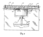
- Figure 4 is a top view of an air flow circulation apparatus according to the present invention; and
- Figure 5 is a view of the apparatus of Figure 4 taken on the line 5-5.
- The present invention will be described in relation to a rotatable centrifugal fan blade assembly specifically adapted for use in a magnetic disk media information storage unit. The particular fan blade assembly described is drawn to dimensions which fit within a space already existing in such a unit.
- Referring now to Figure 1 there is shown a rotatable centrifugal
fan blade assembly 10 according to the present invention viewed from the side to which a rotor 9 (Figure 5) would be attached. Thefan blade assembly 10 consists essentially of aflat disk 56 and fan blades 20-31. The blades 20-31 are orientated along radii extending from a line C, normal to the plane of thedisk 56, at the centre of the disk. The number and spacing of the blades may be varied and the blades themselves may be curved forwardly or backwardly. - Although it is well known in the art, it is relevant to note that the spacing between one blade and the next, for example the
blade 20 to theblade 21 and theblade 21 to theblade 22, varies. This disposition of the blades at varying angular distances from one another is well known to break up the frequency content of the noise generated by the fan blade assembly. So long as the angles distribute the blade/disk weight evenly about the centre of the fan blade assembly, no imbalance will result from such blade distribution. - Figure 2 is a side view of the fan blades 23-29 as they are firmly mounted on (or integrally formed with) the
disk 56. Because of the size limitation of the storage unit for which the fan blade assembly of Figure 1 is developed, the outer diameter of thedisk 56 is 7.5cm (3 inch) and the height of each of the blades 20-31 is 2.5mm (0.1 inch) through most of the body of the blade and 3mm (0.12 inch) at an outer edge 101-112 of the blades 20-31 respectively. The enhanced size of the outer edges 101-112 permits easy mounting and centring of the blades and the disk onto therotor 9. It will be appreciated that thedisk 56 and the blades 20-31 may be formed as an integral unit. - Referring back to Figure 1, the
disk 56 is provided with two (concentric and centrally disposed with respect to an external circumference D4) internal circumferences D1 and D2. In Figure 1, the first internal circumference D1 (the most centrally disposed) provides for the narrowest points ofinlet aperture 19 through thedisk 56. The second internal circumference D2 (disposed distally from the circumference D1) provides for the widest portion of the inlet aperture. If the fan blade assembly is turning in the direction shown by arrow W, that is clockwise, as seen in Figure 1, then the air pressure caused by the rotation of the blades will be greater on the leading edges of the blades than on the trailing edges. This can be seen easily with reference to Figure 3 where the cut-away portion of adisk 80 would be rotating in the direction of the arrow W. A movingblade 81 will develop greater air pressure on a face side or leadingedge 85 than on a rear side ortrailing edge 86. Adisk inlet aperture 82 is expanded by a cut-out 83 defined by aline 84 as if cut from thedisk 80. The cut-out 83, therefore, allows air on the opposite side of thedisk 80 from theblade 81 to enter at areas where the air pressure is lower, i.e. behind theblade 81. It is believed that the extension of thedisk 80 in front of theblade 81 does not allow air to flow back in the wrong direction (opposite to that of entry) to areas where the air pressure is higher, i.e. in front of theblade 81. This special inlet geometry thus effectively increases the inlet size without reducing the effective blade size by allowing the blade to extend to the internal diameter D1 as illustrated in Figure 1, while at the same time allowing for air to enter the fan blade assembly from as wide an area as defined by the circumference D2. - Referring back to Figure 1, it will be noted that one cut-out 44-55 is provided for each of the blades 21-20 respectively. These cut-outs are defined on one side by lines 32-43, respectively, and at their distal end by the circumference D2. For example, the
blade 29 has its cut-out 52 defined by aline 40 extending from the circumference D1 to apoint 89. The exact path of theline 40 and its corresponding lines 32-39, 41-43 for the other blades extends straight from the circumference D1 at the leading edge of one blade to a point on the circumference D2 less than 3.2mm (0.13 inch) from the trailing edge of the next forward blade, and from that point over an arc or flat to that trailing edge. The trailing edge of each blade provides the forward edge of the cut-out, and the central area of the cut-out is open to a completely removed central portion of thedisk 56 defined at its distal perimeter by the circumference D1. These cut-out areas and central circular cut-out defined by the circumference D1 form theinlet aperture 19. For support of the fan blade assembly, some structure (not shown) may be attached to or formed integrally with thedisk 56 which may block portions of the inlet aperture to allow the attachment of a spindle or shaft (not shown), upon which the fan blade assembly may rotate. - It will be appreciated that the cut-outs in the fan blade assembly provide a wider inlet space at the area of low pressure behind the blades and that this wider space tapers to a narrower space when it reaches an area in front of the blades. The exact geometry of the cut-out is not critical but it is important that whatever the geometry is, it provides for a wider inlet at the area of lower pressure and a narrower inlet at the face of the blade, an area of higher pressure. It will be seen from Figure 1 that because of the irregular spacing of the blades 20-31, the slopes of the lines 32-43 are drawn to match (or fit) this irregular pattern or spacing. The larger width portion of the cut-outs may be terminated distally at some point further than the circumference D2 so long as the structural integrity of the overall fan blade assembly is not impaired. Likewise, the larger width portion may be terminated distally within the circumference D2. The specific ratios of circumferences shown may be used to scale up or down the size of a fan blade assembly within the preferred embodiment and the ratios themselves may be altered as well, so long as there is a larger opening on the low pressure side of the blades as described above.
- Referring now to Figures 4 and 5, the
fan blade assembly 10 is seen attached to therotor 9 to form an air flow circulation apparatus 11 according to the present invention with amedia platter 88 connected thereto via aspindle 8. Therotor 9 is connected to a motor (not shown) for rotating theplatter 88 which may, for example, be a magnetic media disk. In this side view apoint 89 coincident with the circumference D2 of Figure 2 is visible. Above thedisk 56 is aconductive element 87 which is electrically connected to the centre of therotor 9 to prevent electrical build-up on theplatter 88. Theconductive element 87 is electrically connected to a drive enclosure housing 7 by means of screws Z and R. In operation, air flow is indicated on Figure 4 by arrows A. The primary air flow is directed through aninterstice 14 which is a space betweencircuit boards aperture 13 in thecircuit board 6. Theaperture 13 is of an appropriate diameter to ensure that the primary air flow proceeds in the direction just indicated, approximately 1.3cm (0.5 inch) for a 7.5cm (3 inch) blade. Air is then directed outwardly by the blades 20-31 through theinterstice 14 to an area outside the housing 7. Clearance between thecircuit board 6 and theconductive element 87 is approximately 1.4mm (0.055 inch) and theinterstice 14 gives a clearance of approximately 4.8mm (0.19 inch) between thecircuit board 5 and the back of thecircuit board 6. These dimensions may, of course, be varied. - In known fan blade assemblies, blades were merely built onto the upper surface of a rotor with no covering such as the
disk 56. The addition of thedisk 56 in thefan blade assembly 10 to quieten the blades decreases their effective width by the width of the disk 56 (that is, otherwise the blades would extend to a width equal to the width shown plus the width of the disk 56). Nevertheless, the design of the fan blade assembly of Figure 1 produces approximately 85 percent of the air flow which is produced by known open bladed assemblies at substantially reduced sound level. The fan blade assembly rotates at approximately 3600 revolutions per minute as conventional. In one known fan blade assembly the fan blades are equally spaced, but 14 blades were required to deliver adequate air flow. The fan blade assembly of Figure 1 produces approximately 85 percent of the air flow of the known fan blade assembly with only 12 blades and eliminates a substantial portion of the noise.
Claims (6)
- A rotatable centrifugal fan blade assembly comprising: substantially parallel circular rotor and disk members (9, 56) at least one of which has a centrally disposed aperture (19), and a plurality of blade members (20 - 31) each disposed in a plane substantially normal to the planes of said rotor and disk members (9, 56), each blade member having leading and trailing edges, characterised in that at least one of the disk members has cut-outs (44 - 55) each of which is located between the connection between two adjacent blade members in said at least one disk, and each of which is defined by a larger area disposed towards the trailing edge of one of said two blade members and by a smaller area disposed toward the leading edge of the other of said two blade members and in that the blade members (20, 31) extend between the rotor (9) and the disk member (56).
- A rotatable centrifugal fan blade assembly as claimed in claim 1, characterised by including a spindle member, the rotor having a surface which is perpendicular to a long axis of the spindle member, said surface having a centrally located substantially cone-shaped mass, the substantially flattened apex of which is directed into said centrally disposed aperture.
- An air flow circulation apparatus comprising: a centrifugal fan blade assembly as claimed in claim 1 characterised in that only one of said disk members (56) has a centrally disposed aperture (19) and the second of said disk members comprises a rotor (9); and further characterised by including a spindle member (8) rotatable by said rotor and extending therefrom in a direction away from said disk member; a housing (7); and at least first and second circuit board member (5, 6) mounted on said housing, the first board member being mounted relatively near to said disk member and provided with an aperture to allow air flow to pass from a side opposite said disk member to a side facing said disk member, said second board member being positioned so that an interstice (14) exists between said first and second circuit board members of sufficient size to permit air flow therebetween.
- An air flow apparatus as claimed in claim 2 characterised by including a magnetic media disk (88) mounted on said spindle member.
- An air flow apparatus as claimed in claim 2 or 3 characterised by including an electrically conductive element (87) between said rotor (9) and said housing (7).
- An air flow apparatus as claimed in any of claims 3 to 5 characterised in that the rotor has a surface which is perpendicular to a long axis of the spindle member, said surface having a centrally located substantially cone-shaped mass, the substantially flattened apex of which is directed into said centrally disposed aperture.
Applications Claiming Priority (2)
| Application Number | Priority Date | Filing Date | Title |
|---|---|---|---|
| US773280 | 1985-09-06 | ||
| US06/773,280 US4662830A (en) | 1985-09-06 | 1985-09-06 | Quiet centrifugal fan |
Publications (3)
| Publication Number | Publication Date |
|---|---|
| EP0216525A2 EP0216525A2 (en) | 1987-04-01 |
| EP0216525A3 EP0216525A3 (en) | 1988-08-24 |
| EP0216525B1 true EP0216525B1 (en) | 1991-11-06 |
Family
ID=25097746
Family Applications (1)
| Application Number | Title | Priority Date | Filing Date |
|---|---|---|---|
| EP86306601A Expired - Lifetime EP0216525B1 (en) | 1985-09-06 | 1986-08-27 | A rotatable centrifugal fan blade assembly and air flow circulation apparatus |
Country Status (6)
| Country | Link |
|---|---|
| US (1) | US4662830A (en) |
| EP (1) | EP0216525B1 (en) |
| JP (1) | JPS6258098A (en) |
| AU (1) | AU6216786A (en) |
| CA (1) | CA1290300C (en) |
| DE (1) | DE3682356D1 (en) |
Families Citing this family (23)
| Publication number | Priority date | Publication date | Assignee | Title |
|---|---|---|---|---|
| JPH0198458U (en) * | 1987-12-22 | 1989-06-30 | ||
| US4917572A (en) * | 1988-05-23 | 1990-04-17 | Airflow Research And Manufacturing Corporation | Centrifugal blower with axial clearance |
| JPH0214500U (en) * | 1988-07-14 | 1990-01-30 | ||
| US5121290A (en) * | 1990-06-25 | 1992-06-09 | At&T Bell Laboratories | Circuit pack cooling using perforations |
| US5171128A (en) * | 1991-01-18 | 1992-12-15 | Twin City Fan & Blower Co. | Fan wheel for a fan or blower assembly |
| JPH05102688A (en) * | 1991-06-21 | 1993-04-23 | Toshiba Corp | Electronic device apparatus |
| JPH0593560A (en) * | 1991-10-03 | 1993-04-16 | Mitsubishi Juko Reinetsu Service Kk | Refrigerant recoverying and reproducing device |
| US5288203A (en) * | 1992-10-23 | 1994-02-22 | Thomas Daniel L | Low profile fan body with heat transfer characteristics |
| US5484262A (en) * | 1992-10-23 | 1996-01-16 | Nidec Corporation | Low profile fan body with heat transfer characteristics |
| US5785116A (en) * | 1996-02-01 | 1998-07-28 | Hewlett-Packard Company | Fan assisted heat sink device |
| US5740013A (en) * | 1996-07-03 | 1998-04-14 | Hewlett-Packard Company | Electronic device enclosure having electromagnetic energy containment and heat removal characteristics |
| US5794685A (en) * | 1996-12-17 | 1998-08-18 | Hewlett-Packard Company | Heat sink device having radial heat and airflow paths |
| US6011331A (en) * | 1997-04-22 | 2000-01-04 | Emerson Electric Co. | Electric motor having an improved airflow cooling system |
| US6213866B1 (en) | 1999-01-26 | 2001-04-10 | John S. Impellizzeri | Ventilating base |
| US6176299B1 (en) | 1999-02-22 | 2001-01-23 | Agilent Technologies, Inc. | Cooling apparatus for electronic devices |
| WO2001002701A1 (en) * | 1999-07-06 | 2001-01-11 | Girgis, Sami, E. | Rotary ram fluid pressurizing machine |
| JP4855227B2 (en) * | 2006-11-30 | 2012-01-18 | 三菱電機株式会社 | Choke coil unit and power device using the same |
| JP5868303B2 (en) * | 2012-10-16 | 2016-02-24 | 横浜ゴム株式会社 | Pneumatic tire |
| US9777743B2 (en) * | 2012-11-06 | 2017-10-03 | Asia Vital Components Co., Ltd. | Centrifugal fan impeller structure |
| US9777742B2 (en) * | 2012-11-06 | 2017-10-03 | Asia Vital Components Co., Ltd. | Centrifugal fan impeller structure |
| US10480525B2 (en) * | 2016-03-08 | 2019-11-19 | Asia Vital Components Co., Ltd. | Fan blade with improved structure |
| US10400780B2 (en) * | 2016-03-08 | 2019-09-03 | Asia Vital Components Co., Ltd. | Structure of fan blades |
| US10100840B2 (en) * | 2016-03-08 | 2018-10-16 | Asia Vital Components Co., Ltd. | Fan wheel structure |
Family Cites Families (7)
| Publication number | Priority date | Publication date | Assignee | Title |
|---|---|---|---|---|
| US2918017A (en) * | 1956-06-11 | 1959-12-22 | Arthur L Collins | Centrifugal pumps |
| US2870959A (en) * | 1956-11-07 | 1959-01-27 | Amana Refrigeration Inc | Blower wheel |
| US4092687A (en) * | 1976-09-07 | 1978-05-30 | Sycor, Inc. | Disc file assembly |
| US4304532A (en) * | 1979-12-17 | 1981-12-08 | Mccoy Lee A | Pump having magnetic drive |
| US4385333A (en) * | 1980-08-04 | 1983-05-24 | International Memories, Inc. | Magnetic disc drive system |
| DE3278616D1 (en) * | 1982-09-29 | 1988-07-07 | Ibm | Electronic assembly with forced convection cooling |
| GB2142786B (en) * | 1983-05-23 | 1986-12-31 | Data General Corp | Disc drive system |
-
1985
- 1985-09-06 US US06/773,280 patent/US4662830A/en not_active Expired - Lifetime
-
1986
- 1986-08-27 DE DE8686306601T patent/DE3682356D1/en not_active Expired - Fee Related
- 1986-08-27 EP EP86306601A patent/EP0216525B1/en not_active Expired - Lifetime
- 1986-08-28 CA CA000517004A patent/CA1290300C/en not_active Expired - Fee Related
- 1986-09-02 AU AU62167/86A patent/AU6216786A/en not_active Abandoned
- 1986-09-04 JP JP61208832A patent/JPS6258098A/en active Granted
Also Published As
| Publication number | Publication date |
|---|---|
| US4662830A (en) | 1987-05-05 |
| JPH0226078B2 (en) | 1990-06-07 |
| JPS6258098A (en) | 1987-03-13 |
| EP0216525A2 (en) | 1987-04-01 |
| EP0216525A3 (en) | 1988-08-24 |
| DE3682356D1 (en) | 1991-12-12 |
| CA1290300C (en) | 1991-10-08 |
| AU6216786A (en) | 1987-03-12 |
Similar Documents
| Publication | Publication Date | Title |
|---|---|---|
| EP0216525B1 (en) | A rotatable centrifugal fan blade assembly and air flow circulation apparatus | |
| JP3481970B2 (en) | High efficiency, low axial profile, low noise axial fan | |
| US7435051B2 (en) | Multi-stage blower | |
| WO2001024676A3 (en) | Impeller and housing assembly with reduced noise and improved airflow | |
| JP3734182B2 (en) | Cooling device in electrical equipment | |
| JP3865504B2 (en) | fan | |
| JPS61279800A (en) | Fan | |
| US6783325B1 (en) | High air flow fan tray bracket | |
| US3237849A (en) | Frame for electrically driven fan | |
| JP2769211B2 (en) | Blower | |
| JPS63289295A (en) | Blower | |
| JP2702755B2 (en) | Axial fan | |
| EP0482032B1 (en) | A fan for an electrically operated machine | |
| JP3368613B2 (en) | Blower | |
| JP2001003900A (en) | Brushless axial fan | |
| JP2000340974A (en) | Fan equipment and electronic apparatus comprising the same | |
| CN220286038U (en) | Range hood, centrifugal fan and blades thereof | |
| JPH0579492A (en) | Lateral flow fan | |
| CN217152339U (en) | Noise-reduction centrifugal wind wheel and range hood | |
| JPH05126093A (en) | Centrifugal fan | |
| JPH11132191A (en) | Multiblade blower | |
| JPH05312187A (en) | Centrifugal pump | |
| JPH0740717Y2 (en) | Centrifugal blower impeller | |
| JP2568573B2 (en) | Fan | |
| JPS6218392Y2 (en) |
Legal Events
| Date | Code | Title | Description |
|---|---|---|---|
| PUAI | Public reference made under article 153(3) epc to a published international application that has entered the european phase |
Free format text: ORIGINAL CODE: 0009012 |
|
| AK | Designated contracting states |
Kind code of ref document: A2 Designated state(s): DE FR GB |
|
| PUAL | Search report despatched |
Free format text: ORIGINAL CODE: 0009013 |
|
| AK | Designated contracting states |
Kind code of ref document: A3 Designated state(s): DE FR GB |
|
| 17P | Request for examination filed |
Effective date: 19890125 |
|
| 17Q | First examination report despatched |
Effective date: 19901023 |
|
| RAP1 | Party data changed (applicant data changed or rights of an application transferred) |
Owner name: SEAGATE TECHNOLOGY INTERNATIONAL |
|
| GRAA | (expected) grant |
Free format text: ORIGINAL CODE: 0009210 |
|
| AK | Designated contracting states |
Kind code of ref document: B1 Designated state(s): DE FR GB |
|
| REF | Corresponds to: |
Ref document number: 3682356 Country of ref document: DE Date of ref document: 19911212 |
|
| ET | Fr: translation filed | ||
| PLBE | No opposition filed within time limit |
Free format text: ORIGINAL CODE: 0009261 |
|
| STAA | Information on the status of an ep patent application or granted ep patent |
Free format text: STATUS: NO OPPOSITION FILED WITHIN TIME LIMIT |
|
| 26N | No opposition filed | ||
| PGFP | Annual fee paid to national office [announced via postgrant information from national office to epo] |
Ref country code: FR Payment date: 19960712 Year of fee payment: 11 |
|
| PGFP | Annual fee paid to national office [announced via postgrant information from national office to epo] |
Ref country code: GB Payment date: 19970721 Year of fee payment: 12 |
|
| PGFP | Annual fee paid to national office [announced via postgrant information from national office to epo] |
Ref country code: DE Payment date: 19970811 Year of fee payment: 12 |
|
| PG25 | Lapsed in a contracting state [announced via postgrant information from national office to epo] |
Ref country code: FR Free format text: LAPSE BECAUSE OF NON-PAYMENT OF DUE FEES Effective date: 19980430 |
|
| REG | Reference to a national code |
Ref country code: FR Ref legal event code: ST |
|
| PG25 | Lapsed in a contracting state [announced via postgrant information from national office to epo] |
Ref country code: GB Free format text: LAPSE BECAUSE OF NON-PAYMENT OF DUE FEES Effective date: 19980827 |
|
| GBPC | Gb: european patent ceased through non-payment of renewal fee |
Effective date: 19980827 |
|
| PG25 | Lapsed in a contracting state [announced via postgrant information from national office to epo] |
Ref country code: DE Free format text: LAPSE BECAUSE OF NON-PAYMENT OF DUE FEES Effective date: 19990601 |