EP0216725A2 - Pacemaker - Google Patents
Pacemaker Download PDFInfo
- Publication number
- EP0216725A2 EP0216725A2 EP86730143A EP86730143A EP0216725A2 EP 0216725 A2 EP0216725 A2 EP 0216725A2 EP 86730143 A EP86730143 A EP 86730143A EP 86730143 A EP86730143 A EP 86730143A EP 0216725 A2 EP0216725 A2 EP 0216725A2
- Authority
- EP
- European Patent Office
- Prior art keywords
- signal
- signals
- pacemaker
- memory
- data
- Prior art date
- Legal status (The legal status is an assumption and is not a legal conclusion. Google has not performed a legal analysis and makes no representation as to the accuracy of the status listed.)
- Granted
Links
Images


Classifications
-
- A—HUMAN NECESSITIES
- A61—MEDICAL OR VETERINARY SCIENCE; HYGIENE
- A61N—ELECTROTHERAPY; MAGNETOTHERAPY; RADIATION THERAPY; ULTRASOUND THERAPY
- A61N1/00—Electrotherapy; Circuits therefor
- A61N1/18—Applying electric currents by contact electrodes
- A61N1/32—Applying electric currents by contact electrodes alternating or intermittent currents
- A61N1/36—Applying electric currents by contact electrodes alternating or intermittent currents for stimulation
- A61N1/362—Heart stimulators
- A61N1/365—Heart stimulators controlled by a physiological parameter, e.g. heart potential
- A61N1/36585—Heart stimulators controlled by a physiological parameter, e.g. heart potential controlled by two or more physical parameters
Definitions
- the invention relates to a pacemaker of the type specified in the preamble of claim 1.
- the disadvantage here is that the response of the pacemaker system to physiological events is extremely limited and complex influences are not possible.
- the invention specified in the characterizing part of claim 1 is based on the object of making it possible to adapt to changing operating conditions in a pacemaker of the type mentioned at the outset, which play an essential role in the cardiac region in particular as a result of changing clinical pictures and also different derivation conditions for measured values.
- the invention is based on the knowledge that it is important for pacemakers to find assignments within almost any nonlinear linkages which result in the desired behavior.
- the ones carried out with the appropriate technical measures Links must also be clearly recognizable for the doctor and the associated pacemaker behavior must be controllable. In contrast to many technical applications in which control or regulating systems are used, in the case of the pacemaker-human system, the system must never fail due to these types of connection.
- the permissible ranges which can be measured in the variation can also be preprogrammed.
- the changeover from the linking of the variables in the sense of a control to the prescribed "regulation" by external programming means can be switched on and off, this switching on and off can also take place automatically, so that the system is switched back to "controlled” operation if the approximation according to a programmed strategy does not result in a sufficiently precise adaptation.
- the body temperature can also be preferably calibrated together under steady-state conditions. With changing load conditions, the differences in the measured values of these sensors provide an indication of load fluctuations during operation and, when the peripheral temperature increases compared to the temperature in the central body area, cause an increase in the cardiac output. If one of the sensors fails, the remaining one delivers a stationary value.
- the measured variables containing the respective physiological parameters and containing transducers are subjected to an analog / digital conversion, and the digital value obtained forms - at least indirectly - the address or address information for selecting the stored output data, which are stored in memory locations in a variable memory can be recorded so that the functional relationship for a set of output variables can be freely determined by changing the memory contents.
- the measures according to the invention result in the advantageous possibility of linking the input variables of a plurality of measurement sensors for the same physiological variable.
- This consists in that the partial addresses for addressing the memory locations of the one memory are generated by combining the digital values formed from the measured values to form a common digital value.
- the tabulation of the functional relationship is not exclusively by assigning pairs of values, i.e. by storing a size corresponding to the respective absolute value in the respective memory location, but that the memory locations may also contain other information about the functional relationship instead of the absolute value - for example as a slope measure or as respective differences to a reference value.
- Another possibility of linking two variables relating to the same physiological parameters is that the digitized values are each subjected to a mathematical averaging and the averaged output values are subjected to further processing.
- a corresponding read-only memory is also provided, which contains empirical values that can be accessed by a large number of patients, so that if the other variable memories have not yet been programmed, a limited operation is possible. Switching over to reading out memory values from these respectively assigned read-only memories can be done by changing a single bit (memory selection bit), so that at least one emergency operation is possible even in the event of a malfunction.
- a linear timer which simulates one or more time constants is now optionally switched on in the digital processing branch before or after a tabulated addressable memory.
- the type of time constant (s) or the corresponding behavior of a control element (D or I behavior) or a delay time can be programmed by entering the relevant parameters.
- digital replication by an appropriate computer which evaluates the associated transmission function digitally is preferred.
- time constants take into account the fact that in some physiological measurable variables in the body, quantities of body fluids or other substance quantities are involved, which require a certain time until they together uniformly assume the physical or chemical measured variable. Examples include blood temperature or blood oxygen saturation, blood pH, systolic intervals, etc.
- the values that characterize the signal processing can be specifically changed by appropriate programming or when the system is self-adjusted, those values that characterize the system in question.
- Two blood temperature sensors one of which is located in a peripheral part of the circuit and the other is provided in the area of the body center, provide different measured values when the physical stress state changes. In the state of rest, however, both sensors deliver the same values after some time if they are intact. A check can therefore also be carried out on an implanted system if the patient is examined at rest (and possibly under different loads).
- the control of the temporally stationary behavior of a measured value and thus of a stationary output signal of the transducer enables a module for temporally averaging, which outputs only those signals that are subject to limited temporal fluctuations as valid.
- the signals of the two aforementioned sensors for the blood temperature in the stationary case are redundant, and allow conclusions to be drawn about their function or a mutual calibration.
- the heart actions during non-intervening operation are available for calibration as an additional reference signal.
- a corresponding control of the signals supplied by a measuring sensor results from the fact that the signals which are set in the body and which characterize physiological variables can only change at a limited time rate. So if signal values deviate greatly from immediately preceding signals, there is also an indication of a malfunction.
- the signals of such sensors which are placed differently in the body circulation, are adapted to one another during processing by the system shown here before they are brought together in a manner which corresponds to the physiological conditions.
- Part of the physical body's own control system can be simulated by a suitable time constant and by a storable - possibly non-linear - relationship.
- the calibration can preferably be carried out in such a way that a stimulation rate is first set in the case of stationary exercise, which corresponds to the relevant exercise case, the natural cardiac activity of the patient at earlier times also being able to be used as a comparison.
- the provision of further — possibly external — sensors, which are connected to the system for information exchange shown here by means of the interactive communication of the programming means, is favorable, with the system being fully programmable the link between the signal flow paths and the influencing variables can also be preselected.
- the behavior of an already implanted pacemaker can be adapted both to the further findings of the treating physicians about the patient in general or his further clinical picture, but in addition, advances in the medical application of the technology shown here can also be taken into account retrospectively.
- the technical implementation of the programmability of the links is preferably carried out in such a way that an additional memory is provided in the manner of a matrix, in which memory locations are provided for a number of the modules described above (table memory, time constant memory, link modules, averager) which contain the addresses of Record storage locations in which the input and output data for these blocks are to be stored.
- the parameters characterizing the electrostimulation have different intensities on the stimulation behavior of the pacemaker, the stimulation preferably being influenced in such a way that the cardiac output is adapted to the current physical load.
- a module connected downstream of the last linking element serves to adapt the size influencing the stimulation of the heart in such a way that the performance of the heart changed due to the stimulation (preferably via the stimulation rate) only within that due to the parameters determined physiologically in the body Performance range is adjusted, which the patient's heart is able to scan.
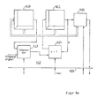
- FIG. 1 first shows the basic structure of a pacemaker with means for processing at least one input measured variable for the physiological influencing, preferably of the heart rate.
- At the input end there is therefore at least one measured value pickup for a measurement variable that can be recorded inside or outside the body, which can be used for the physiological control of the stimulation rate or the basic heartbeat interval — in the case of a demand pacemaker.
- a measurement variable that can be recorded inside or outside the body, which can be used for the physiological control of the stimulation rate or the basic heartbeat interval — in the case of a demand pacemaker.
- These are quantities which differ from such signals which can be derived electrically in the heart and which each serve only to prevent stimulation in competition with chamber intrinsic actions or to synchronize the stimulation pulses and only concern a current heart action.
- all stimulation variables can be changed as a function of the "physiological" input variables, for which a connection for a stimulation behavior can be found that is valid over several heartbeats.
- These are all parameters relevant to the stimulation that are not related to just one specific heart action, but relate to the stimulation behavior in general. This also includes the parameters which are "programmable" in pacemakers and which can also be found in the future and which
- Corresponding sensors are in the form of temperature-dependent resistors for measuring the blood temperature, as measuring electrodes for determining impe Danzcardiographischen (electroplethysmographic) data, as a photoelectric sensor for determining the blood oxygen saturation by means of a light barrier, as chemical probes for determining the pH value or as a pressure or sound sensor for measurement values that are related to the mechanical contraction, known in principle.
- the measurement variables recorded in the heart itself and forming a measure of the chamber filling which are thus already linked to a variable that characterizes the cardiac output - and thus the performance of the heart - can be advantageously used to influence the stimulation parameters (especially the heart rate ).
- additional physiological measurement values can be obtained from the electrical voltage potentials recorded on the heart, such as the Q-T interval, which can also be used for heart rate control.
- the analog output signals of the transducers are each fed to a downstream analog / digital converter, which converts the input signals into corresponding signals which can be processed with the described digital storage means or signal processors.
- the processing The data words forming a measured value are carried out by means of a microprocessor and its peripheral components for data storage and processing.
- FIG. 1 the physical (hardware) structure of the pacemaker system shown below is shown.
- This is a microprocessor system 110 which can communicate bidirectionally with an external control unit 120 as a programming unit by means of telemetry.
- the implantable unit contains a conventional multiprogrammable system III which interacts with the ventricle and / or the atrium via one or two electrodes.
- a parameter memory 112 is provided as an interface to the rest of the pacemaker system, which at the same time serves as a buffer for data exchange with the conventional pacemaker system.
- the parameter memory initially contains the data which the multiprogrammable pacemaker 101 has as operating parameters, i.e. Control variables are specified. These variables form the values of a one or two chamber pacemaker that can be set by external programming, whereby the operating mode (from V00 to DDD) is also programmable.
- those operating parameters are also recorded in the memory 112, which were recorded in the patient's body via further sensors and derived from "physiological" input variables. In the case of the Q-T intervals, however, they can also be derived via the stimulation electrodes themselves.
- the microprocessor system surrounding this block serves to determine further control variables, preferably the basic rate, and to supplement the system 111 in this respect. This has the advantage that the use of system 101 in a conventional manner does not require additional knowledge beyond that which is necessary when using known multiprogrammable pacemakers.
- the pacemaker 111 can also be operated without "physiological" measured variables, the basic stimulation rate being predefined by external programming in accordance with the conventional pacemakers.
- the signal and data processing necessary for the operation of the pacemaker part 111 can also be carried out by the CPU 113 of the microprocessor system.
- a RAM memory 114 and a ROM memory 115 as well as an input / output unit 116 are assigned to the CPU 113, by means of which the data traffic with the peripheral modules 111 and 125 is carried out. It should be mentioned that with the system shown the signal processing takes place as described below, the memories and data links shown there being generated by appropriate programming, so to speak "software" and are present in RAM or ROM memory areas . The system appears to the user zer like an arrangement with the physical structure described, which could also be implemented in hardware accordingly.
- Both the parameter memory 112 is connected to the input / output unit 116 as well as various measuring sensors 117, 118, 119, 120, which supply the recorded signals of the unit 116 by means of digital / analog converters 121 to 124.
- the signal recorders were mentioned at the beginning and are attached to or on the patient's body - especially on the stimulation electrode or the housing of the pacemaker itself.
- the signal processing by the CPU is serial, the individual assemblies of the structure to be described below being included in the data exchange, if necessary according to corresponding interrupt requirements, so that the signal processing - adapted to the time requirements of the signals - is carried out clocked virtually simultaneously.
- a data transmission from and to the implanted unit takes place by means of the control unit 120 Telemetry assembly 151, which communicates with the corresponding telemetry assembly 125.
- the control unit has its own CPU 152, which exchanges data with its own RAM memories 153 or ROM memories 154. There is also an input / output unit 155 to which the telemetry unit 151 and a video interface 156 are connected. The video interface is connected to a monitor 157, which, in accordance with the program present in the external unit 150, enables data from the implantable system to be queried and changed. It is of particular importance that the entire operator guidance and the means for graphical representation are available in the external unit, including data about the general structure of the implantable system. The graphic processing of the data obtained and the specifications necessary for programming the internal system provide a convenient mode of operation which gives the operator information about the operating state of the implantable system at all times.
- the programming is carried out by means of a light pen 158, with which information can be selected by contacting the screen. Accordingly, a pressure-sensitive screen can be used, in which the selection of information is possible by touching the screen surface.
- a selection of screen pages can be made (corresponding to the "scrolling" in a file), preference being given both to the operation and to the assessment of the data arising during operation a preparation in graphical representations is made in internationally understandable symbols.
- the individual functional areas of the implantable system can be selected separately, a search tree structure leading from the parameter areas that relate to the basic functioning of the pacemaker to more subtle links, which can be reached with different access codes to a depth assigned to the relevant user.
- a log 159 can be printed out for documentation purposes by means of a printer 159.
- the external design of the assemblies 110 and 150 is also shown in FIG. 1 and shows that the implantable part has the dimensions of a normal pacemaker 160, while the external communication part 161 also has a graphical display area 163 in addition to an antenna part 162 which can be placed on the patient's body .
- the following description relates to details of the assembly 116 and in particular to the linking of the "physiological" input variables of the measuring transducers 117 to 120 and the data link and their control.
- FIG. 2 shows the matrix-like memory structure of a map provided for controlling the system, the memory locations of the matrix being searchable by column and row address signals and the numerical value available at the addressed memory location being able to be read in or out.
- Each map is common with one Seed address feature searchable, so that on the one hand a simplified addressing is possible in normal operation, but on the other hand, a reconfiguration of the processing and a closed reading or changing the content of a map in connection with the external communication unit can be done easily.
- the corresponding data contents differ from one another by additional attributes, which are differentiated in corresponding downstream data discriminators (not shown).
- the common address feature of each map memory enables direct access to the content of the respective entire memory area for reading in and reading out or changing data.
- the map data for the data processing preferably have access addresses which can be called up in accordance with those of auxiliary memories which contain only linkage, selection or other auxiliary information such as data sets which can be read out by the communication unit and which contain graphic or characteristic data for the pacemaker type in question.
- control and access level 306 This direct access is indicated by the control and access level 306 in the lower part of the drawing.
- a data field can therefore also form a memory, the information of which form the determination of the sequence in relation to the interconnection of inputs and outputs of various characteristic map components.
- the storage unit shown in FIG. 2 need not form a physical or hardware unit in the storage area of the system, as shown.
- the structure in question can also be generated purely by software.
- the memory unit according to FIG. 2 - which is also synonymously referred to here as "map memory” or “memory matrix”, forms part of a "cell” shown in FIG. 3 as a signal processing module, in which the memory unit is still surrounded by auxiliary modules, which are advantageously in a module-like manner Structure are provided for each map and are linked in the networking, so that only the inputs and outputs of this cell appear as interfaces. Blocks that are not required for a specific application are deactivated by loading corresponding control parameters in the auxiliary memory (as described below).
- the signals from various transducers are combined in a block 301, taking into account of each signal of each transducer associated G ewichtungssignal.
- the block 301 also simultaneously forms a switch module, which uses the access level 306 to select various signals as input (ie address signals) and, depending on the "switch position" (influenced by the selection information from the control level 306), different signals by means of the following map for variable addressing of the output of signals from the subsequent map field memory 302 in the form of digitized amplitude information.
- the selected input signals each form partial address signals, which overall sweep the memory area of the subsequent map.
- the input data can not only be switched by block data to be supplied separately in block 301, but also (individually or jointly) subjected to logical or mathematical operations, ie data can be selected, moved or "processed” in some other way.
- work areas or work characteristic curves can be selected in this way, the selection data which characterize permissible address areas being recorded in a corresponding characteristic map.
- the selection data identify only those signal data as permissible addresses which have a data value that deviates from "zero".
- the address range that can be selected can thus be restricted or influenced in any other way.
- a limited number of frequently used linking operations are kept in stock and can be called up directly from the control level.
- More complex operations can also be subjected to input variables by means of a correspondingly programmed map memory, which permits any evaluation of input signals by appropriately specifying output signal values as data values in the relevant memory locations addressed by combination of the input signals.
- input signals can also be subjected exclusively to a logical combination in block 301, the subsequent map either being "bridged” with regard to data processing by a corresponding control signal (not shown) or it is rendered ineffective by the map in question in that the memory locations in each case their addresses are stored so that the input signals appear again at the output of block 302.
- the control level 306 itself can - as is also shown below with reference to FIG. 4a - also be reached by output signals of the map memory 302, so that the signal linkage can be influenced via the blocks 301 as a function of signals contained in maps.
- a data record contained in a corresponding memory 302 thus contains, in addition to an instruction as to whether it is signal, selection or linkage or other auxiliary information, in the case of the selection information the names of the relevant map cells, the output and input for the one to be treated Form signal.
- the selection information the names of the relevant map cells, the output and input for the one to be treated Form signal.
- linking information there is also the agreed name for a logical or mathematical operation.
- several data links in the overall structure of the system can also be influenced. This is because they are determined by link memories - as described below.
- the pacemaker shown is "self-learning" in such a way that the configuration of the processing with regard to the selection of measured values and processing can largely adapt automatically to the input signals found and their changes.
- Such changes are in particular: the shutdown of disturbed transducers and, in particular, the transition from an operation determined by several physiological transducers to the operating mode influenced by one or no such transducers. While two transducers for the same size can often be operated in differential mode, a single remaining transducer can often - with a correspondingly increased probability of error - also still contribute effectively to the control.
- evaluation numbers are also included in the processing, which, in the case of an evaluated summary, contain a statement about the value of an input signal with regard to its expected reliability.
- the evaluated summary is preferably carried out with standardized input signals. It combines input signals containing similar information to form a combined output signal, this is done according to the mathematical laws for averaging measured values with weighting. This averaging can be done either by digital processing via calculation based on a formula or by means of a storable table in the form of the map field memory.
- additional evaluations of the signal in question are made with regard to disturbances inherent therein, expressed by unexpected fluctuations or superimposed amplitudes.
- the corresponding circuits for interference detection correspond to circuits that are already used for the elimination of disturbed input signals in medical electronics.
- the module 301 is therefore supplied with digitized data in various ways.
- the data is brought together in each case at an input level according to a link which can be predetermined via the outer programming and access level 306.
- the input signals G ll to G 1n are used for addressing the lines of the map memory 302, the data G 1 to G 3 for addressing the lines, while the data 1 to 3 relate to the data contents - that is to say the data to be written into the individually addressed memory locations.
- the type of link in the memory 301 can be predetermined via the external control (access or programming) level, various mathematical links (summation, multiplication) or logical links being selectable so that the data is added up, multiplied or can be converted in each case according to a logical condition, the logical conditions apart from AND, AND / OR or other known links which can be implemented by logic gates also consisting of "larger", “smaller” or “equal” relationships. It can also be specified that a certain fixed logical value is output if the specified condition is met.
- the assembly 301 thus permits the processing of signals with a fixed logic level as well as those with a variable level in digital representation.
- the number of levels of the component 301 increases accordingly if the map memory 302 is multidimensional, as is indicated by the perspective layering in FIG. 3. An additional addressing level is required for each dimension.
- the representation in FIG. 3 has a rather symbolic form. Any other appropriate design of the real memory is possible.
- the circuit 302 is followed by a programmable signal processing module 303, which enables time-dependent linear processing of the signal value, while in the module 302 there is a non-linear tabular relationship between the input and output variable as a map.
- the two modules 302 and 303 are to be influenced by external programming means via the control level, the coefficients of a linear differential equation which determines the temporal transition behavior (in a likewise matrix-like arrangement corresponding to the other data) preferably being in the module 303 modules) can be entered.
- the temporal processing is carried out by the internal microprocessor in accordance with systems which, by means of digitally adjustable parameters, enable the digital simulation of linear physical systems.
- the separation of non-linear and linear system components of signal processing results in a simple system structure with simple adaptability, which can be easily set externally.
- the signal processing part 303 can also cause a signal delay in such a way that a predetermined signal delay (by designating the corresponding number of clock signals of a system clock) is specified by means of a certain parameter, the output signals then corresponding to the set number in the manner of a digital delay line (shift register ) appears delayed at the output only by the specified number of clock signals compared to the input.
- a predetermined signal delay by designating the corresponding number of clock signals of a system clock
- the representations shown in block 303 provide examples of a possible transition behavior, which is described by the characteristic values of the linear differential equations in question.
- the assemblies 304 and 305 generate a label for the reliability of the signal output by the module 300, which is fed to the input of the subsequent corresponding module, so that in each stage there is a measure of the reliability which can be taken into account in the subsequent combination .
- Faulty signals can be eliminated in this way by using other error-free signals instead in the subsequent processing. In this way it can be determined whether the relevant input is subject to interference signals. An indication of this is given when, for measured values which are by their nature subject to a slow change (blood temperature etc.), signals are processed which have an erratic character.
- one criterion is to be seen in the fact that when comparing two or more signals, which show a similar course of change under certain conditions, deviations from this similarity occur.
- the digital input signals in the form of additional information of at least one bit are an indication of the reliability of the corresponding measured value - or after the time-dependent processing in a module 303 - for linking Measured values is added.
- the arrangement 304 for weighting contains a mean value generator and a comparator for fault detection, to which the input signal from the assembly 301 is fed directly and the output signal of the fault detection is supplied, with the output signal of 304 being displayed in the event of deviations which go beyond a predetermined amount is that the input signals may only have a reduced reliability, so that the weighting in the evaluation must be reduced accordingly.
- the signal G summarizes the weighting signals from pre-stages that have already carried out a corresponding evaluation. It is added to the level 304 in the assembly 305 and the evaluated summary is made available as the output signal of the level 300.
- the construction Groups 304 and 305 can also be switched via control level 306, depending on signal data as well as by external programming.
- the "cells" containing maps can contain various types of information. For example, they form read-only memories - even without linking their data contents to other cells, whereby they can be addressed by physiological measured values or output signals from other characteristic value memories. In this way, areas that are traversed by the (address-forming) input signals can be specially marked for subsequent stages or for external communication with a graphic representation. Permissible work areas or highlighted areas can be specified or logical links. If the memory contents are not intended as output signals for subsequent memory cells for addressing or as a data signal, such characteristic maps can also only serve to inform the user or to control the communication system in order to highlight certain operating areas for external communication in the graphics used there.
- FIG. 4 the arrangement of the assemblies described above is illustrated in a matrix-like structure, as is assumed for the addressing of the individual modules within their linking erknüpfungstechnisch in a V 406th
- a function group that can be addressed by means of row and column numbers each comprises the functional elements, one as such a cell which can be selected by addressing, consisting of summing part 402, map 403, linear timer 404 and weighting unit 405 (corresponding to the L representation in FIG. 3).
- These function groups are repeated in any row and column grid, with the aid of two matrix-like storage areas, on the one hand, for each function module with respect to its inputs, the "grid square" of the module whose output signal is fed to this module. Since the summing unit 402 has several inputs, several columns and address labels can be provided for each module.
- the output signal data are assigned to the subsequent cells, as described above.
- the input variables of the pacemaker system are each assigned to a memory element of a row, so that the corresponding input can be used to determine whether the output signals of which modules are to form the relevant parameters.
- the first memory 406 contains the signal links valid in normal operation - programmable by the external communication part.
- the system structure for an alternative operating state is predefined in a second memory 407 organized in a matrix-like manner, again in each case in column and row assignment.
- FIG. 4a shows how a histogram memory can be formed by linking two map cells 410 and 411 (corresponding to cells 401 in FIG. 4) and a counter cell 412, which, when read out later, provides information about the behavior of the pacemaker system.
- cell 410 forms a (programmable) reference field, in the memory locations of which values which are addressable by output signals from preceding cells or else by input signals, values are recorded which serve as reference variables in comparison operations.
- a counter matrix 411 counter values are recorded in the individual memory locations, which are also organized in a matrix-like manner, which record the occurrence of certain events - normally the exceeding or falling below the corresponding reference value contained in cell 410.
- memory cells 410 and 411 are addressed in parallel.
- the input signal which is to be compared with the values recorded in the reference cell 410, is fed to a comparator 413, which compares it with the respectively addressed signal in the reference cell 410 according to an externally specifiable condition.
- the content of the counter map 411 according to FIG. 4a is preferably fed to a block 300 according to FIG. 3 as an input variable and, after corresponding logical decisions, the operating behavior is changed by means of a corresponding map.
- the map matrix addressed based on the counter reading is followed by a further map memory for calling up different maps which change existing links (memory 406 in FIG. 4) or influence the parameter memory (112 in FIG. 1) or Switch or replace maps that serve as read-only memories accordingly, and it is advantageous if the parameter memory 112, which influences the conventional behavior of the pacemaker, is also constructed in accordance with the maps that control the physiological control Partly possible according to the processing of the physiological parameters.
- “Physiological” measured variables which are determined in the conventional part of the pacemaker, such as the QT distance or a spontaneous frequency that arises under certain loads, can thus be transferred as an interface to the rest of the system via the parameter memory 112. This interface is also suitable for transmission when determining physiological parameters via the electrode or other measurement transducers provided in the conventional area of the pacemaker.
- the output of block 411 (or any other module) is resettable by expensive plane via a corresponding control of the S 306, a switching element, which emits in response to the output of the block 411 a signal to the control plane, which affects a connection matrix 406, in turn, the Controls blocks 301 (in Figure 3).
- Maps can be switched, ie exchanged, evaluated differently or changed in their link with previous and subsequent maps. How these changes are to be made is recorded in the maps that define the links.
- the system thus also becomes “self-learning", whereby only a number of or a certain frequency of events lead to a change in the configuration.
- Decisive for the change in the system behavior are disturbances of predetermined frequency or intensity or the non-occurrence of predetermined operating states, which make a specific pacemaker configuration necessary from the point of view of therapy, so that the stimulation can always be carried out in the simplest mode of operation - which is clearest for the doctor.
- the memory can also be used to check the success of the programming carried out by him.
- the physiological quantities recorded in the body are each linked to the other signals of the same type on corresponding “linking levels”, so that physically correct further processing takes place.
- an adaptation of the temporal and amplitude behavior of the signal to be processed and linked is carried out between two linking stages (if necessary), so that the signal in question at the respective linking point has a further physiological variable that is important in controlling cardiac activity. is adjusted.
- the system can work in parallel with the signals that are running in the body, which influence the cardiac activity, and the body's own control processes, and in the different linkage levels the respective physiological signals at the relevant level can also be detected by additional measurement sensors and either used as control signals or else flow into the further signal processing according to their value.
- a separate map memory is provided for the "calibration" of transducers.
- signals that are on the one hand a measure of the power requirement and on the other hand characteristic of the cardiac output itself as well as those sizes that are only available for a short time are also fed in correctly and a statement about the processing ability of the preceding stages enable or allow the corresponding processing parameters (blocks 302 and 303) to be set correctly.
- the signal processing can also be influenced by feedback of a quantity which allows a conclusion to be drawn about the cardiac output. This feedback takes place in such a way that the physiological measured values are combined in the processing and transformed in such a way that they form a measure of the current need for the cardiac output.
- a criterion of the actual cardiac output derived from the heart is used as a comparison criterion, whereby this heart time volume is taken into account as feedback when selecting the stimulation values in the context of a table.
- the table setting the stimulation parameters is updated on the basis of the cardiac output actually set with the stimulation with the relevant parameters. In the case of input addresses which require a certain cardiac output, the stimulation parameters or signal values which lead to the necessary stimulation parameters are entered.
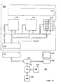
- FIG. 5 shows a pacemaker system as it is presented to the attending doctor on the screen of his control device in the block diagram. At the same time, it forms the basis for the functional description of a pacemaker system, as can also be generated in a conventional manner, for example in terms of hardware.
- Figure 5 shows the implantable part, the arrangement in question is of course not limited to implantable systems, but can also be used accordingly for external pacemakers.
- Block 501 shown in dashed lines, indicates the areas of the human body located outside the heart, from which physiological measurement variables are derived which relate to the function of the pacemaker, while heart 502 interacts with the system via the stimulation electrodes and measurement sensors placed in the heart.
- a conventional pacemaker 503 is self-sufficient and, if necessary, multiprogrammable via a programming unit 504. (In a system shown in FIG. 1, which reproduces the real links, programming is carried out by the uniform control unit by means of the parameter memory 112.)
- a block 504 which can be called up as a page on the control unit and contains the conventionally programmable parameters in familiar identification. Different types of pacemakers can be implemented completely.
- the translation of the parameters actually set in the implantable system into a conventional system is carried out in the external control part, a selector switch being provided which allows different implementations.
- FIG. 4 The blocks provided with strongly drawn borders are assemblies in accordance with FIG. 4, which contain the functional elements in accordance with FIGS. 2 and 3 and are logically connected in the manner shown by means of the linking matrix indicated in FIG. 4.
- FIG. 5 shows examples of links in a preferred embodiment, the mode of operation being reproduced in detail below. It can be seen that the output signals of various analog transducers 505 to 509 in the block diagram in the course of signal processing in each case in different groups can be linked.
- the analog input variables are converted beforehand by means of analog / digital converters 510 to 514.
- the output variables of the converters are each fed to evaluation modules 515 to 519, with an individual, ie programmable, adaptation being carried out in these modules.
- This adaptation includes the elimination of non-linearities of the transducers by appropriate programming of the characteristic diagrams shown above, and enables the programming of time-dependent changes in the transmission characteristic and of weighting factors.
- the transmission behavior of a transducer can be changed by programming the map.
- the sensor 506 detects the oxygen partial pressure in the right ventricle or the respiration rate
- the sensor 507 is used to determine the blood temperature, preferably in the vena cava. While the partial pressure of oxygen or the respiration rate are a good measure of the current oxygen deficit - provided the corresponding map has been calibrated accordingly - the blood temperature has an integrating character and only rises or falls with a certain time delay.
- the time constant within the block 517 is provided with a differentiating characteristic by appropriate programming, so that preferably the differential changes in blood temperature as a measure of an activity or idle state are linked to the output variable of block 516.
- the superimposition can take place either linearly by weighted sum formation or else by means of a map, with one input variable addressing a coordinate axis in each case in a two-dimensional map.
- the link in module 520 is also dependent on a number of digital output signals from sensors 521 to 523, which - as previously described with reference to FIG. 2 - cause switching of the map in block 520.
- a mercury switch 521 which is implanted with the pacemaker housing, thus recognizes the current position of the patient (lying down, standing) and thus provides an additional evaluation option for the load on the patient.
- a digital activity sensor 522 also recognizes whether accelerations and decelerations above a predetermined limit occur, whether the patient is currently at rest or in motion and switches the map located in block 520 accordingly.
- the measurement processing is controlled by a common system clock to ensure synchronicity.
- a digitally operating fault detection system detects whether a load variable can currently not be determined. For example, if, for example, the respiration rate is recorded by means of a microphone, strong noises caused by a coughing of the patient or the like are generated by an additional microphone present in the interference detection unit 523. recognized and used for blanking the measured values of the transducer 506, which could be done by switching the corresponding characteristic diagram or else by reducing the weighting factor by connection to block 516.
- An additional sensor 505 forms a recording of the patient's activity with an analog output signal.
- the accelerations and decelerations are recorded in terms of amplitude and frequency and processed further via modules 510 and 515.
- the block 524 serves to combine the output variable of the block 520 with a signal which indicates the actual physical activity.
- the output signal of block 524 thus indicates the cardiac output (cardiac output).
- the output signals of blocks 514 and 520 are partially redundant and can be related to each other to increase reliability in the following map.
- An additional transmission module 525 which is included in the telemetry system according to FIG. 1, is of particular importance. External load data determined by means of an ergometer can be fed into block 525 via this module, whereby both the output variable of block 515 and that of block 520 are related to the current load by external programming. By inserting the current one Load data into the memory locations of the map in block 525 addressed by means of the output signals of blocks 515 and 520 can be checked or calibrated, so that the HZV requirement is calibrated, so that the reliability of the system is increased or a regulation is generated. By transmitting and comparing the load signal available outside the body and comparing it with the corresponding signal received inside the body, there is a possibility of calibration or a link to the rules.
- Two further sensors 508 and 509 record signals which also relate to the cardiac output.
- the transducer 508 for the stroke volume (via the systolic intervals as a pressure transducer or microphone or by means of impedance cardiography or a combination of both methods) forms a measure of the volume adaptation of the heart in response to a predetermined physical load.
- the further measured value sensor 509 for the QT distance determines a measure of the current frequency requirement from the signals recorded in the heart on the stimulation pulses, likewise using a corresponding characteristic map.
- Either the outputs of blocks 524 and 526 are superimposed on one another and control the heart rate (as the basic rate of demand pacemaker 503) directly.
- This control can be carried out taking into account the current stroke volume (arrow from block 518 to 527), so that all those variables which influence the heart rate are processed in a combined manner and a cardiac output volume which is favorable due to the determined variables is obtained.
- the additional evaluation of the slave volume in block 527 can take place with a different weighting than that entered in block 526 as a tendency for the frequency to be observed, so that in particular control oscillations are avoided here. If there are a large number of stable values to be detected, the stroke volume can also be omitted entirely during processing in block 526. The same applies to the size Qt.
- the pacemaker can also be used in controlled operation, only the link in module 527 having to be changed.
- the cardiac output requirement in the map is compared in accordance with block 527 with the product of the stroke volume and the current rate, the rate being increased or decreased until the product of stroke volume and frequency corresponds to the cardiac output volume specified by block 524. It can be seen that different control or regulating mechanisms can be realized by different combinations can, whereby in particular within the map the rate can be varied step by step using a search strategy so that the greatest possible amount of time is achieved.
- An additional fault detector 528 switches off the signals recorded in the heart when there are faults detected, the fault criteria corresponding to those which prevent the pacemaker from controlling the heart from demand pacemakers.
- An arrow from the output of block 527, which is directed to parameter memory 504, indicates that the programmed parameters of the pacemaker are being changed. This includes in particular an expansion of the programmed time variables, such as refractory or blanking times with decreasing frequency. This relationship can generally be related to the timing of the pacemaker.
- the programmable change in block 504 is preferably carried out by means of a map stored there, the memory of which contains the programmed operating values of the pacemaker and is addressed by a variable derived from the frequency.
- the pacemaker 503 is in particular a single-chamber pacemaker for ventricular stimulation, since in this way there is no need to insert an additional electrode into the atrium.
- the transducers for other physiological variables are arranged in the pacemaker housing or in the ventricular electrode, so that the implantation technique is not different from the conventional one Pacemakers differentiate or compared to AV pacemakers is.
- FIG. 5 a shows how the individual characteristic maps 531 to 534 are addressed by the external communication unit, how they are addressed in the corresponding cells — as shown above — and how the data located there are read out or new data read in.
- the addressing takes place independently of the rest of the operation of the pacemaker 535, which is determined by non-physiological data, this control being switched inactive during the programming of the physiological part (signal fixed value).
- the basic stimulation rate and the other physiologically determined operating parameters are set during programming to a value corresponding to the patient's idle state.
- the configuration data (map 534) contained in the pacemaker which define the data-related linkage of the maps, call up a graphic representation that corresponds to this configuration.
- the individual maps are shown as blocks on a screen or LCD screen and can be called up by programming with a light pen or, in the case of a touch-sensitive display, by pressing.
- the respective map or the corresponding module appears enlarged on the screen so that the data fields marked with a cursor can be changed.
- any individual can be used in so-called "window" technology structures of the link diagram can be called up and changed.
- the communication system shown can be inserted into a standard data processing system (PC or the like), the communication interface to the pacemaker forming an additional populated printed circuit board which can be plugged into the PC and is supplied with the associated software programmed to contain the aforementioned functions, so that the communication part requires only small memory costs with an existing PC. Nevertheless - in accordance with the existing expansion of the PC - there is a very large processing capacity, which enables simultaneous calling and the display of even complex representations, whereby the operator guidance gives the user hints and warnings for the configuration programming of the system. A protocol of the programming process is created via a printer, which documents the set operating state of the pacemaker.
- PC data processing system
- the pro grammed data entries or the configuration can be stored simultaneously in a central memory, so that the operating parameters of the pacemaker in question can preferably also be called up via external data communication options and are available to any doctor in emergencies.
- the programming part is in particular also designed as a communication terminal, so that complex software, which also affects the operator prompting and the configuration of the pacemaker, is stored centrally and transmitted to the respective communication terminal. In this way it is ensured that the latest software is used in each case during the programming, so that further development - taking into account the respective hardware status - can also take place after the implantation.
- the experience with a certain type of pacemaker in a large number of patients with the corresponding clinical picture can therefore subsequently contribute to the further development or improvement of the already implanted system.
- the representation shown on the screen of the communication unit corresponds, for example, to a block diagram as shown in FIG. 5.
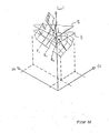
- the characteristic diagrams shown in FIGS. 6a to 6c represent examples of relationships between variables stored in matrix-like memories, as are used in the pacemaker concept described above.
- the representation is preferably carried out in three-axis coordinate systems so that a perspective graphic representation can take place in the external control unit. If only two coordinate axes are used, they are displayed in the plane. An additional display option is by superimposing two characteristic diagrams in one diagram.
- the characteristic diagrams selected here are based on three-axis systems, since the associated memory is then constructed as a two-dimensional matrix, so that the corresponding numerical values can also be represented on the plane, i.e. on the screen, and thus either by graphic input using a light pen or can be changed by entering numbers with cursor addressing.
- the numerical values K 1 and K 2 can be two different input variables that are linked or else it is a measurement variable and a parameter - for example the current heart rate or the blood temperature.
- a parameter - for example the current heart rate or the blood temperature.
- a calibration can be carried out by spatially aligning the two maps, or a regulation of a predetermined strategy can be implemented, which consists, for example, in that the volume is made between two overlaid maps or by the dependent variable gradual variation of an independent variable a relative or absolute maximum is sought.
- the independent variable represents a measured value
- the dependent variable according to the strategy above all be changed and the change is monitored according to a difference criterion.
- one of the axes forms the time axis, so that cardiac events of the past, in particular as histograms, are stored by means of the characteristic diagrams and can be transferred from the heart to the control unit using the same graphic display means, which also affect the rest of the pacemaker system.
- the time-dependent behavior of the pacemaker as a function of cardiac events can be represented in the control part using graphic means, as is known from conventional pacemakers from the display of the stimulation rate as a function of the repetition rate of spontaneous cardiac actions.
- the control functions of the maps are permanently programmed, they serve as storage for the variable values in the control, which serve as the basis for the control criterion, the control process representing the state by graphically displaying the current field of the most recently performed values for the attending physician of the system graphically.
- the system - as stated - can be switched between a control and a regulating system at any time. This switchover can take place automatically as a function of previous signals if a corresponding map assignment is provided.
- FIG. 6b shows the cardiac output as a function of the heart rate and the stroke volume in a further map.
- This map has for the control of the Pacemaker is of particular importance since the cardiac output is a measure of the performance of the heart, especially since the change in the heart rate is not a sufficient criterion in itself if the achievable stroke volume is disregarded.
- the map reproduced in FIG. 6b shows the purely mathematical relationship that arises arithmetically, with two different load curves L1 and L2 being shown, provided that a constant physical load when controlling the pacemaker is also countered by a corresponding, corresponding cardiac output.
- the stroke volume is shown to be changeable between the minimum and maximum physiologically permissible values, with the same correspondingly valid for the heart rate.
- the pacemaker With the pacemaker, however, only the heart rate can be influenced, while the stroke volume adjusts itself according to the existing adaptability of the heart.
- a product with the heart rate it provides a measure of the current performance of the heart
- a reduction or enlargement - based on a constant heart rate - is a criterion in that the body's internal control system requests an increase or decrease in the cardiac output, insofar as this is desired Adaptability is still present in the patient concerned.
- the representation according to FIG. 6c is used to enable the doctor to make a better assessment of the consequences of the individual control or regulating variables and, if appropriate, a correspondingly selected operating characteristic of the control.
- FIG. 6c is another map The dependence of the stroke volume on the heart rate and the load is reproduced, the axial direction being chosen in accordance with that in the map according to FIG. 6b in order to enable a simplified comparison. It is shown that the stroke volume is limited to higher values when the adaptability of the heart is limited, the stroke volume being reduced at higher frequency values because the ventricular filling is reduced, particularly in the case of the ischemic heart.
- the working range of the pacemaker is to be determined, whereby the automatic adjustment by map overlay assumes that the external load size must not deviate from the cardiac output by more than a predetermined amount if the performance of the heart the burden should be adequate in the long term.
- the characteristic curve according to FIG. 6c is in particular set in such a way that frequency ranges in which increasing load a reduction in stroke volume (in relation to the corresponding stroke volume value at a higher frequency) are avoided, since in such a case a higher frequency value leads to better cardiac output.
- FIG. 6d the link between the control of the heart rate and a plurality of input signals after an exclusive OR link is shown using the diagram known from the previous figures.
- the display is also an example of a system configuration in which the signal processing path is dependent on a signal event itself.
- the heart rate is initially influenced in a manner linked to the stroke volume, as shown above.
- the arrow shown in the diagram assumes, however, that the change in stroke volume in the patient concerned (or a corresponding size) can only be used to a limited extent for heart rate control.
- a further load-related parameter of the pacemaker for example the blood temperature
- the recorded blood temperature is converted in a corresponding map into the associated load level B, which is linked to the output signal of the map, which contains the rate depending on a size correlated with the stroke volume, by means of an OR relationship, so that the control of the heart rate is taken from the blood temperature if an assigned heart rate is not reached when a certain temperature level is reached.
- the load level as a function of the temperature is represented by a horizontal surface which shifts vertically in a level-like manner. If the level exceeds a load value that is greater than a corresponding one If the load is adequately covered by the cardiac output resulting from the cardiac output, the temperature sensor takes over the "guidance" by influencing the heart rate so that the cardiac output is adjusted to the direction.
- the load is only adjusted by physiological stroke volume adaptation, which can lead to unsatisfactory adaptation behavior at peak loads.
- Even changing the programming of the characteristic curve (F1) in the available work area does not create any change here, since with a lower increase in heart rate with an increase in PEP, only stroke volume adaptation due to LVEP is used to a greater extent even at reduced rates.
- the heart rate is additionally increased during exercise by means of an additional performance-related physiological parameter determined in the patient's body when the product of stroke volume and heart rate is no longer adequate for the physical activity is.
- a measured variable must then be recorded which is exactly correlated with the current stroke volume, while the parameter PEP recorded here provides information only for a portion of the stroke volume adaptation.
- a map is used which, depending on the current heart rate, switches over to the control by means of another parameter.
- the signals PEP and LVEP form sound transducers in the can by means of a compression spring taken signals that are representative of the stroke volume.
- a suitably programmed map which contains data linking instructions for different maps and ensures that above a predetermined rate level, the blood temperature at a value that corresponds to a high level of physical activity, the blood temperature contributes to the further rate increase that the cardiac output is adapted to the actual load and the additional adaptability of the stroke volume (which does not need to be recorded when controlled by PEP) also forms an additional reserve at higher frequencies.
- the blood temperature will, for example, generate an additional programmable relative change in the heart rate as a difference value, so that there is no need to take account of measurement errors inherent in the absolute values. (An additional measurement of the absolute stroke volume is possible, for example, by electroplethysmographic measurement.)
- Such a control has the advantage that short-term adjustments to the stroke volume do not lead to excessive frequency jumps, but nevertheless an additional adaptation of the cardiac output to the load is possible in the case of prolonged heavy physical exertion (the blood temperature rises with a delay).
- the metrological links by programming the system precisely determine its technical function on the one hand and make it an automatic control or regulating system - on the other hand, the attending physician can control the functioning of the system at any time by checking the memory allocations and intervene as required .
- the embodiment of the invention is not limited to the example given above. Rather, a large number of variants are conceivable which make use of the solution shown, even in the case of fundamentally different types.
- the implementation is not limited to implementation with discrete logic modules, but can also advantageously be implemented with programmed logic, in particular using a microprocessor.
Abstract
Description
Die Erfindung betrifft einen Herzschrittmacher der im Oberbegriff des Anspruchs 1 angegebenen Art.The invention relates to a pacemaker of the type specified in the preamble of
Es ist bei künstlichen Herzschrittmachern bekannt, eine Anpassung an die physiologischen Gegebenheiten in der Weise vorzunehmen, daß eine Umschaltung von Betriebszuständen (MODES) in Abhängigkeit von im Herzen auftretenden Ereignissen vorgenommen wird.It is known in artificial pacemakers to adapt to the physiological conditions in the To make a way that a switching of operating states (MODES) is carried out depending on events occurring in the heart.
Daneben war es schon vorher bekannt, diese Umschaltungen auch von außen über externe Programmiermittel vorzunehmen (Multiprogrammierbarer Schrittmacher).In addition, it was previously known to carry out these changes from the outside using external programming means (multiprogrammable pacemaker).
Bei diesen Veränderungen handelt es sich jedoch stets um solche Signale, welche das Verhalten des Schrittmachers in der Weise betrifft, daß die Konkurrenz der Stimulationsimpulse mit Spontanaktionen vermieden werden soll.However, these changes are always signals which affect the behavior of the pacemaker in such a way that the competition of the stimulation pulses with spontaneous actions is to be avoided.
Nachteilig ist dabei, daß die Reaktion des Schrittmachersystems auf physiologische Ereignisse damit äußerst eingeschränkt ist und komplexe Beeinflussungen nicht möglich sind.The disadvantage here is that the response of the pacemaker system to physiological events is extremely limited and complex influences are not possible.
Der im kennzeichnenden Teil des Anspruchs 1 angegebenen Erfindung liegt die Aufgabe zugrunde, bei einem Herzschrittmacher der eingangs genannten Gattung eine Anpassung an sich ändernde Betriebsbedingungen zu ermöglichen, die gerade im kardialen Bereich infolge sich verändernder Krankheitsbilder und ebenfalls veränderlichen Ableitungsbedingen für Meßwerte eine wesentliche Rolle spielen.The invention specified in the characterizing part of
Der Erfindung liegt die Erkenntnis zugrunde, daß es bei Herzschrittmachern darauf ankommt, innerhalb von nahezu beliebigen nichtlinearen Verknüpfungen Zuordnungen aufzufinden, welche in das gewünschte Verhalten bewirken. Die mit den entsprechenden technischen Maßnahmen vorgenommenen Verknüpfungen müssen darüberhinaus für den Arzt anschaulich erkennbar und das zugehörige Schrittmacherverhalten kontrollierbar sein. Im Gegensatz zu vielen technischen Anwendungen, bei denen Steuerungs- oder Regelsysteme verwendet werden, darf es im Falle des Systems Schrittmacher-Mensch in keinem Fall zu einem Versagen des Systems kommen, welche durch diese Arten der Verknüpfung bedingt ist.The invention is based on the knowledge that it is important for pacemakers to find assignments within almost any nonlinear linkages which result in the desired behavior. The ones carried out with the appropriate technical measures Links must also be clearly recognizable for the doctor and the associated pacemaker behavior must be controllable. In contrast to many technical applications in which control or regulating systems are used, in the case of the pacemaker-human system, the system must never fail due to these types of connection.
Auch aus diesem Grund lassen sich bekannte Regelungstechniken hier nicht ohne weiteres verwenden, da sie theoretische Ableitungen voraussetzen, welche in der Anpassung des Regelsystems an den Menschen zu komplex wären, als daß sie in ihren Auswirkungen vollständig überschaut werden könnten. Es gilt also ein System zu finden, bei dem die Meßwertverarbeitung zu jedem Zeitpunkt für den behandelnden Arzt überschaubar ist.For this reason, too, known control techniques cannot be used here easily, since they presuppose theoretical derivations which would be too complex to adapt the control system to humans, so that their effects could be completely overlooked. It is therefore important to find a system in which the processing of measured values is manageable for the attending doctor at all times.
Da die Lebensgewohnheiten dieses Patienten, die mögliche Schädigung des Herzens und die Bedingungen für das Wohlbefinden nicht standardisierbar sind erweisen sich die beanspruchten Maßnahmen insbesondere auch wegen der Anpassung an wechselnde Krankheitsbilder als besonders günstig.Since the lifestyle of this patient, the possible damage to the heart and the conditions for well-being cannot be standardized, the measures claimed prove to be particularly favorable, in particular because of the adaptation to changing clinical pictures.
Bei einer anderen bevorzugten Weiterbildung lassen sich die zulässigen Bereiche, welche bei der Variation durchmessen werde.n können, ebenfalls vorprogrammieren.In another preferred development, the permissible ranges which can be measured in the variation can also be preprogrammed.
In anderen Weiterbildungen ist die Umschaltung von der Verknüpfung der Größen im Sinn einer Steuerung zu der vorgeschriebenen "Regelung" durch äußere Programmiermittel ein- und ausschaltbar, wobei diese Ein- und Ausschaltung ebenfalls selbsttätig erfolgen kann, so daß auf den "gesteuerten" Betrieb zurückgeschaltet wird, wenn durch die Annäherung entsprechend einer programmierten Strategie keine genügend genaue Anpassung erreicht wird.In other developments, the changeover from the linking of the variables in the sense of a control to the prescribed "regulation" by external programming means can be switched on and off, this switching on and off can also take place automatically, so that the system is switched back to "controlled" operation if the approximation according to a programmed strategy does not result in a sufficiently precise adaptation.
Werden für die Ermittlung der Körpertemperatur zwei Meßwertaufnehmer verwendet, so können diese ebenfalls bevorzugt bei stationären Verhältnissen gemeinsam geeicht werden. Bei wechselnden Belastungsverhältnissen geben die Differenzen der Meßwerte dieser Aufnehmer im Betrieb einen Anhaltspunkt für Belastungsschwankungen und veranlassen bei einer Zunahme der peripheren Temperatur gegenüber der Temperatur im zentralen Körperbereich eine Heraufsetzung des Herzzeitvolumens. Bei Ausfall eines der Meßwertaufnehmer liefert der verbleibende einen stationären Wert. Bei anderen Weiterbildungen der Erfindung werden die mittels Meßwertaufnehmern enthaltenden, die jeweiligen physiologischen Parameter kennzeichnenden Meßgrößen einer Analog/Digital-Wandlung unterzogen und der erhaltene Digitalwert bildet - mindestens mittelbar - die Adresse oder eine Adresseninformation zur Auswahl der gespeicherten Ausgangsdaten, die in Speicherplätzen eines veränderlichen Speichers festgehalten werden können, so daß der funktionale Zusammenhang für einen Satz Ausgangsgrößen durch Veränderung der Speicherinhalte frei festgelegt werden kann.If two sensors are used to determine the body temperature, these can also be preferably calibrated together under steady-state conditions. With changing load conditions, the differences in the measured values of these sensors provide an indication of load fluctuations during operation and, when the peripheral temperature increases compared to the temperature in the central body area, cause an increase in the cardiac output. If one of the sensors fails, the remaining one delivers a stationary value. In other developments of the invention, the measured variables containing the respective physiological parameters and containing transducers are subjected to an analog / digital conversion, and the digital value obtained forms - at least indirectly - the address or address information for selecting the stored output data, which are stored in memory locations in a variable memory can be recorded so that the functional relationship for a set of output variables can be freely determined by changing the memory contents.
Durch die Maßnahmen nach der Erfindung ergibt sich die vorteilhafte Möglichkeit, die Eingangsgrößen mehrerer Meßwertaufnehmer für dieselbe physiologische Größe miteinander zu verknüpfen. Diese besteht darin, daß die Teiladressen zur Adressierung der Speicherplätze des einen Speichers durch Zusammensetzung der aus den Meßwerten gebildeten Digitalwerte zu einer gemeinsamen Digitalwert erzeugt werden.The measures according to the invention result in the advantageous possibility of linking the input variables of a plurality of measurement sensors for the same physiological variable. This consists in that the partial addresses for addressing the memory locations of the one memory are generated by combining the digital values formed from the measured values to form a common digital value.
Es soll hinzugefügt werden, daß die Tabellierung des funktionalen Zusammenhangs selbstverständlich nicht ausschließlich direkt durch Zuordnung von Wertepaaren, d.h. durch Abspeicherung eines dem jeweiligen Absolutwert entsprechenden Größe in dem jeweiligen Speicherplatz vorgenommen werden muß, sondern daß die Speicherplätze anstelle des Absolutwerts auch andere Information über den funktionalen Zusammenhang - beispielsweise als Steigungsmaß oder als jeweilige Differenzen zu einem Bezugswert enthalten kann.It should be added that, of course, the tabulation of the functional relationship is not exclusively by assigning pairs of values, i.e. by storing a size corresponding to the respective absolute value in the respective memory location, but that the memory locations may also contain other information about the functional relationship instead of the absolute value - for example as a slope measure or as respective differences to a reference value.
Eine andere Möglichkeit der Verknüpfung zweier denselben physiologischen Parameter betreffenden Größen besteht darin, daß die digitalisierten Werte jeweils einer mathematischen Mittelung unterzogen werden und die gemittelten Ausgangswerte der Weiterverarbeitung unterzogen werden.Another possibility of linking two variables relating to the same physiological parameters is that the digitized values are each subjected to a mathematical averaging and the averaged output values are subjected to further processing.
Durch die zuvor beschriebenen Maßnahmen der tabellierten Verarbeitung von nichtlinearen funktionalen Zusammenhängen und deren Verknüpfung ist es möglich, die vom Körper abgeleiteten physiologischen Meßgrößen in einer Art und Weise zu verarbeiten, welche dem behandelnden Arzt stets eine gute Übersicht über die aktuellen Signalzustände gibt.The previously described measures of tabular processing of nonlinear functional relationships and their linking make it possible to process the physiological measurement variables derived from the body in a manner which always gives the attending physician a good overview of the current signal states.
Bei einer anderen bevorzugten Ausführung ist neben den in den programmierbaren Kennfeldspeichern noch jeweils ein entsprechender Festwertspeicher vorgesehen, der Erfahrungswerte enthält, auf die bei einer großen Zahl von Patienten zurückgegriffen werden kann, so daß, wenn die übrigen veränderlichen Speicher noch nicht programmiert sind, trotzdem ein eingeschränkter Betrieb möglich ist. Das Umschalten zum Auslesen von Speicherwerten aus diesen jeweils zugeordneten Festwertspeichern kann durch Änderung eines einzigen Bits (Speicherauswahl-Bit) erfolgen, so daß auch in einem eventuellen Störfall mindestens ein Notbetrieb möglich ist.In another preferred embodiment, in addition to those in the programmable map memories, a corresponding read-only memory is also provided, which contains empirical values that can be accessed by a large number of patients, so that if the other variable memories have not yet been programmed, a limited operation is possible. Switching over to reading out memory values from these respectively assigned read-only memories can be done by changing a single bit (memory selection bit), so that at least one emergency operation is possible even in the event of a malfunction.
Ein weiteres Problem bei der Verarbeitung einer im Körper ableitbaren Größe besteht darin, daß bei dieser Signalverknüpfung vielfach auch der zeitabhängige Verlauf von Eingangs- und Ausgangsgrößen berücksichtigt werden muß. Da die im Vorstehenden dargestellte tabellarische Verknüpfung im Kennfeld zwar die Berücksichtigung nichtlinearer Zusammenhänge zuläßt, können jedoch zeitliche Vor- bzw. Nachwirkungen nicht ohne weiteres berücksichtigt werden, auch würde die Programmierung nichtlinearer zeitabhängiger Vorgänge die Übersichtlichkeit sehr stark beeinträchtigen bzw. wäre aufgrund der komplexen zu berücksichtigenden zusammenhänge mit zumutbarem Aufwand überhaupt nicht ausführbar.Another problem with the processing of a variable that can be derived in the body is that with this signal linkage the time-dependent course of input and output variables must also be taken into account in many cases. Since the table shown above Linking in the map allows the consideration of nonlinear relationships, but temporal pre- and after-effects can not be taken into account easily, the programming of nonlinear time-dependent processes would also impair the clarity very much or would not be at all due to the complex relationships to be taken into account with reasonable effort executable.
Gemäß der bevorzugten Ausführung wird nun gegebenenfalls jeweils im digitalen Verarbeitungszweig vor bzw. nach einem tabelliert adressierbaren Speicher ein lineares Zeitglied eingeschaltet, welches eine oder mehrere Zeitkonstanten simuliert. Dabei ist die Art der Zeitkonstante(n) bzw. das entsprechende Verhalten eines Regelgliedes (D- oder I-Verhalten) oder ein Verzögerungszeit durch Eingabe der betreffenden Parameter programmierbar. Neben der physikalischen Realisierung durch analoge Bauelemente (aktive Übertragungsglieder mit Speichergliedern und Widerständen, wobei die Widerstände durch die Programmierung veränderbar sind, wird die digitale Nachbildung durch einen entsprechenden Rechner, der die zugehörige Ubertragungsfunktion digital auswertet bevorzugt. Bei dieser Weiterbildung der Erfindung wird in günstiger Weise die Erkenntnis berücksichtigt, daß bei einer Anordnung, welche aufgrund von zusätzlich im Körper ableitbaren Größen ein Ausgangssignal zur elektrischen Stimulation des Herzens bildet, eine genügende Genauigkeit auch dann erzielt werden kann, wenn die zeitabhängigen und die nichtlinearen Teile der übertragungsfunktionen konzentriert und getrennt verarbeitet werden.According to the preferred embodiment, a linear timer which simulates one or more time constants is now optionally switched on in the digital processing branch before or after a tabulated addressable memory. The type of time constant (s) or the corresponding behavior of a control element (D or I behavior) or a delay time can be programmed by entering the relevant parameters. In addition to the physical implementation by means of analog components (active transmission elements with memory elements and resistors, the resistances being changeable by programming), digital replication by an appropriate computer which evaluates the associated transmission function digitally is preferred. This further development of the invention is advantageous the knowledge takes into account that with an arrangement which forms an output signal for electrical stimulation of the heart on the basis of variables which can additionally be derived in the body, sufficient accuracy can also be achieved if the time-dependent and the non-linear parts of the transfer functions are concentrated and processed separately.
Derartige Zeitkonstanten tragen der Tatsache Rechnung, daß bei einigen physiologischen im Körper ableitbaren Meßgrößen Mengen von Körperflüssigkeiten- oder anderen Substanzmengen beteiligt sind, bei denen es eine gewisse Zeit erfordert, bis sie gemeinsam gleichmäßig die physikalische oder chemische Meßgröße annehmen. Als Beispiel dafür sei die Bluttemperatur oder die Blutsauerstoffsättigung, der pH-Wert des Blutes, die systolischen Intervalle etc. genannt.Such time constants take into account the fact that in some physiological measurable variables in the body, quantities of body fluids or other substance quantities are involved, which require a certain time until they together uniformly assume the physical or chemical measured variable. Examples include blood temperature or blood oxygen saturation, blood pH, systolic intervals, etc.
Durch die Trennung der Einstellung von Zeitkonstanten und der übrigen tabellarischen Programmierung lassen sich beim Abgleich der die Signalverarbeitung kennzeichnenden Werte durch entsprechende Programmierung oder bei Selbstabgleich des Systems gezielt diejenigen Werte verändern, welche das betreffende System wesentlich kennzeichnen.By separating the setting of time constants and the other tabular programming, the values that characterize the signal processing can be specifically changed by appropriate programming or when the system is self-adjusted, those values that characterize the system in question.
So ist es bei der Auswertung der Körpertemperatur zur Auswertung in Richtung auf eine die Belastung des Patienten kennzeichnenden Größe vorteilhaft, durch Verarbeitung des Meßwertes für die Körpertemperatur (in digitaler Form) zunächst eine differenzierende Komponente anzubringen, um die integrierende am Wärmetransport beteiligten Blutmenge zu kompensieren.Thus, when evaluating the body temperature for evaluation in the direction of a variable characterizing the load on the patient, it is advantageous to first apply a differentiating component by processing the measured value for the body temperature (in digital form) in order to compensate for the integrating amount of blood involved in the heat transport.
Um die Störsicherheit der Anordnung zu vergrößern, sind Maßnahmen vorgesehen, welche Fehler erkennen und in ihrer Auswirkung dadurch eliminieren, daß auf Ersatzfunktionen umgeschaltet wird.In order to increase the interference immunity of the arrangement, measures are provided which recognize errors and eliminate their effect by switching to replacement functions.
Zwei Meßwertaufnehmer für die Bluttemperatur, von denen einer in einem peripheren Teil des Kreislaufs angeordnet und der andere im Bereich des Körperzentrums vorgesehen ist, liefern unterschiedliche Meßwerte, wenn sich der körperliche Belastungszustand ändert. Im Zustand der Ruhe liefern beide Aufnehmer jedoch nach einiger Zeit gleiche Werte, wenn sie intakt sind. Eine Kontrolle läßt sich also auch bei einem implantierten System durchführen, wenn der Patient dazu jeweils in Ruhe (und gegebenenfalls bei unterschiedlichen Belastungen) untersucht wird. Die Kontrolle des zeitlich stationären Verhaltens eines Meßwertes und damit eines stationären Ausgagssignals des Meßwertgebers ermöglicht eine Baugruppe zur zeitlichen Mittelwertbildung, welche nur diejenigen Signale als gültig ausgibt, die begrenzten zeitlichen Schwankungen unterliegen. Somit sind also die Signale der beiden vorgenannten Meßwertaufnehmer für die Bluttemperatur im stationären Fall redundant, und lassen Rückschlüsse auf ihre Funktion zu bzw. eine gegenseitige Eichung.Two blood temperature sensors, one of which is located in a peripheral part of the circuit and the other is provided in the area of the body center, provide different measured values when the physical stress state changes. In the state of rest, however, both sensors deliver the same values after some time if they are intact. A check can therefore also be carried out on an implanted system if the patient is examined at rest (and possibly under different loads). The control of the temporally stationary behavior of a measured value and thus of a stationary output signal of the transducer enables a module for temporally averaging, which outputs only those signals that are subject to limited temporal fluctuations as valid. Thus, the signals of the two aforementioned sensors for the blood temperature in the stationary case are redundant, and allow conclusions to be drawn about their function or a mutual calibration.
Zur Eichung stehen weiterhin neben einem ergometrisch aufgenommenen Signal als zusätzliches Bezugssignal die Herzeigenaktionen bei nicht intervenierendem Betrieb zur Verfügung.In addition to an ergometrically recorded signal, the heart actions during non-intervening operation are available for calibration as an additional reference signal.
Eine entsprechende Kontrolle der von einem Meßwertaufnehmer gelieferten Signale ergibt sich aus der Berücksichtigung der Tatsache, daß die sich im Körper einstellenden, physiologische Größen kennzeichnenden Signale nur mit einer begrenzten zeitlichen Rate ändern können. Weichen also Signalwerte in starkem Maße von unmittelbar vorangegangenen Signalen stark ab, so ist damit ebenfalls ein Indiz für eine Fehlfunktion gegeben.A corresponding control of the signals supplied by a measuring sensor results from the fact that the signals which are set in the body and which characterize physiological variables can only change at a limited time rate. So if signal values deviate greatly from immediately preceding signals, there is also an indication of a malfunction.
Im Voranstehenden wurde bereits erwähnt, daß verschiedene Meßwertaufnehmer für dieselbe physiologische Größe (beispielsweise die Körpertemperatur) an verschiedenen Stellen des Körpers vorgesehen sein können, um eine erhöhte Sicherheit bei der Erfassung zu ermöglichen. Hierbei werden aber auch zusätzliche Informationen geliefert, welche die zeitliche Steuerung beeinflussen können. Dabei ist zunächst einmal vorauszuschicken, daß gemäß einer bevorzugten Ausführung der Erfindung die Signale derartiger unterschiedlich im Körperkreislauf plazierten Meßwertaufnehmer bei der Verarbeitung durch das hier dargestellte System vor der Zusammenführung in einer den physiologischen Verhältnissen entsprechenden Weise aneinander angepaßt werden. Dabei ist durch eine geeignete Zeitkonstante und durch einen abspeicherbaren - gegebenenfalls nichtlinearen - Zusammenhang ein Teil des physikalischen körpereigenen Regelsystems nachbildbar.It has already been mentioned in the foregoing that different measuring sensors for the same physiological variable (for example the body temperature) can be provided at different points in the body in order to enable increased security in the detection. However, additional information is also provided that can influence the timing. First of all, it should be noted that, according to a preferred embodiment of the invention, the signals of such sensors, which are placed differently in the body circulation, are adapted to one another during processing by the system shown here before they are brought together in a manner which corresponds to the physiological conditions. Part of the physical body's own control system can be simulated by a suitable time constant and by a storable - possibly non-linear - relationship.
Die Eichung läßt sich mit dem hier dargestellten System bevorzugt in der Weise vornehmen, daß zunächst bei stationärer Belastung eine Stimulationsrate eingestellt wird, welche dem betreffenden Belastungsfall entspricht, wobei auch die natürliche Herztätigkeit des Patienten zu früheren Zeitpunkten als Vergleich herangezogen werden kann.With the system shown here, the calibration can preferably be carried out in such a way that a stimulation rate is first set in the case of stationary exercise, which corresponds to the relevant exercise case, the natural cardiac activity of the patient at earlier times also being able to be used as a comparison.
Bei anderen vorteilhaften Weiterbildungen der Erfindung ist das Vorsehen weiterer - gegebenenfalls externer - Meßwertaufnehmer, die mittels der interaktiven Kommunikation der Programmiermittel mit dem hier dargestellten System zum Informationsaustausch verbunden sind - günstig, wobei im Rahmen der vollständigen Programmierbarkeit des Systems auch die Verknüpfung der Signalflußwege bzw. der Einflußgrößen vorwählbar ist. Auf diese Weise kann das Verhalten eines bereits implantierten Schrittmachers sowohl den weiteren Erkenntnissen der behandelnden Ärzte über den Patienten allgemein bzw. dessen weiteren Krankheitsbild angepaßt werden, daneben können aber auch Fortschritte bei der medizinischen Anwendung der hier dargestellten Technik überhaupt nachträglich noch Berücksichtigung finden. Die technische Realisierung der Programmierbarkeit der Verknüpfungen erfolgt bevorzugt in der Weise, daß ein zusätzlicher Speicher nach Art einer Matrix vorgesehen ist, in dem für eine Anzahl der vorstehend beschriebenen Baugruppen (Tabellenspeicher, Zeitkonstantenspeicher, Verknüpfungsbausteine, Mittelwertbildner) Speicherplätze vorgesehen sind, welche die Adressen von Speicherplätzen aufnehmen, in denen die Ein- bzw. Ausgangsdaten für diese Bausteine abzulegen sind.In other advantageous developments of the invention, the provision of further — possibly external — sensors, which are connected to the system for information exchange shown here by means of the interactive communication of the programming means, is favorable, with the system being fully programmable the link between the signal flow paths and the influencing variables can also be preselected. In this way, the behavior of an already implanted pacemaker can be adapted both to the further findings of the treating physicians about the patient in general or his further clinical picture, but in addition, advances in the medical application of the technology shown here can also be taken into account retrospectively. The technical implementation of the programmability of the links is preferably carried out in such a way that an additional memory is provided in the manner of a matrix, in which memory locations are provided for a number of the modules described above (table memory, time constant memory, link modules, averager) which contain the addresses of Record storage locations in which the input and output data for these blocks are to be stored.
Die die Elektrostimulation kennzeichnenden Parameter wirken sich mit unterschiedliche Intensität auf das Stimulationsverhalten des Schrittmachers aus, wobei die Stimulation bervorzugt in der Weise beeinflußt wird, daß die Herzleistung der aktuellen körperlichen Belastung angepaßt wird.The parameters characterizing the electrostimulation have different intensities on the stimulation behavior of the pacemaker, the stimulation preferably being influenced in such a way that the cardiac output is adapted to the current physical load.
Eine dem letzten Verknüpfungselement nachgeschaltete Baugruppe dient dazu, die Stimulation des Herzens beeinflussende Größe derart anzupassen, daß die aufgrund der Stimulation veränderte Leistung des Herzens (vorzugsweise über die Stimulationsrate) dem aufgrund der physiologisch im Körper ermittelten Paramter nur innerhalb desjenigen Leistungsbereichs angepaßt wird, den das Herz des Patienten zu überstreichen in der Lage ist.A module connected downstream of the last linking element serves to adapt the size influencing the stimulation of the heart in such a way that the performance of the heart changed due to the stimulation (preferably via the stimulation rate) only within that due to the parameters determined physiologically in the body Performance range is adjusted, which the patient's heart is able to scan.
Es ist ersichtlich, wie sich mittels des hier dargestellten Systems für den Arzt in übersichtlicher Form das gesamte Reaktions- und Steuerverhalten in anschaulicher Weise programmieren und überblicken läßt.It can be seen how the system shown here can be used to clearly program and overview the entire reaction and control behavior for the doctor.
Die Anpassung an bestimmte Therapieformen ist ohne Schwierigkeiten möglich, wobei beispielsweise beim ischämischen Herzen diejenigen Frequenzbereiche, in denen das Herz eine adäquate Leistungsfähigkeit zeigt, durch Stimulation mit der betreffenden Rate bei nichtspontaner Herzaktivität durch Programmierung gezielt "anwählbar" sind, so daß im Betrieb aufgrund der nichtlinearen Eigenschaften des Systems jene "leistungsfähigen Arbeitsbereiche" des Herzens aufgesucht werden.The adaptation to certain forms of therapy is possible without difficulty, for example in ischemic heart those frequency ranges in which the heart shows adequate performance can be "selected" by stimulation at the relevant rate with non-spontaneous cardiac activity through programming, so that in operation due to the nonlinear properties of the system seek out those "powerful work areas" of the heart.
Vorteilhafte Weiterbildungen des Ausführungsbeispiels sind in den Unteransprüchen gekennzeichnet bzw. werden bei der nachstehenden Darstellung zusammen mit einer bevorzugten Ausführung der Erfindung näher beschrieben. Es zeigen:
- Fig. 1 die Systemstruktur eines Ausführungsbeispiels der Erfindung,
- Fig. 2 ein im Speicherbereich des Ausführungsbeipiels benutztes Kennfeld,
- Fig. 3 die in einem Signalverarbeitungsbaustein vorhandenen Elemente unter Einschluß eines Kennfeldes nach
Figur 2, - Fig. 4 eine Anordnung von Signalverarbeitungsbausteinen zur programmierbaren Verknüpfung,
- Fig. 4a eine Hilfsbaustein zur Signalspeicherung und Verknüpfung im Zusammenhang mit den Anordnungen gemäß Figuren 3 und 4,
- Fig. 5 ein gemäß der Erfindung mit den vorstehenden Bausteinen realisierter Herzschrittmacher in Blockdarstellung
- Fig. 5a ein Bild zur Veranschaulichung des Zusammenwirkens der Kommunikationseinheit mit den Bausteinen gemäß Figuren 4 und 4a sowie
- Fig. 6a bis 6e verschiedene Kennfelder in räumlicher Darstellung zur Erläuterung verschiedener Varianten des Ausführungsbeispiels.
- 1 shows the system structure of an embodiment of the invention,
- 2 shows a map used in the memory area of the exemplary embodiment,
- 3 shows the elements present in a signal processing module, including a map according to FIG. 2,
- 4 shows an arrangement of signal processing modules for programmable linking,
- 4a shows an auxiliary module for signal storage and linking in connection with the arrangements according to FIGS. 3 and 4,
- 5 shows a pacemaker realized according to the invention with the above components in block diagram
- 5a is an image to illustrate the interaction of the communication unit with the components according to FIGS. 4 and 4a and
- 6a to 6e different maps in a spatial representation to explain different variants of the embodiment.
Bei dem nachstehend beschriebenen Ausführungsbeispiel eines Herzschrittmachers gemäß der Erfindung werden verschiedene Baugruppen, welche der Signalbearbeitung dienen und als matrixartig organisierte bzw. Kennfelder enthaltende Speicher beschrieben sind, in ähnlicher Konfiguration mehrfach benutzt, so daß es für das Verständnis ausreichend ist, wenn diese Grundbaugruppen in ihrer Funktion allgemein beschrieben werden. Bei den späteren Darstellungen des funktionalen Zusammenwirkens der Gesamtanordnung entsprechend den wiedergegebenen Blockschaltbildern kann dann auf die Beschreibung von Einzelheiten der Funktionsweise dieser Baugruppen verzichtet werden.In the exemplary embodiment of a pacemaker according to the invention described below, various assemblies which serve for signal processing and are described as memories organized in a matrix-like manner or containing maps are used several times in a similar configuration, so that it is sufficient for understanding that these basic assemblies are in their Function generally described. In the later depictions of the functional interaction of the overall arrangement in accordance with the block diagrams shown, the description of details of the functioning of these assemblies can then be dispensed with.
In Figur 1 ist zunächst einmal der grundsätzliche Aufbau eines Herzschrittmachers mit Mitteln zur Verarbeitung minstens einer Eingangs-Meßgröße zur physiologischen Beeinflussung vorzugsweise der Herzrate dargestellt.FIG. 1 first shows the basic structure of a pacemaker with means for processing at least one input measured variable for the physiological influencing, preferably of the heart rate.
Eingangsseitig ist also mindestens ein Meßwertaufnehmer für eine innerhalb oder außerhalb des Körpers aufnehmbare Meßgröße vorgesehen, welche zur physiologischen Steuerung der Stimulationsrate bzw. des Herzschlaggrundintervalls - im Falle eines Demand-Schrittmachers - heranziehbar ist. Dabei handelt es sich um solche Größen, welche von solchen elektrisch im Herzen ableitbaren Signalen verschieden sind, die jeweils nur zur Verhinderung einer Stimulation in Konkurrenz zu Kammereigenaktionen bzw. zur Synchronisation der Stimulationsimpulse dienen und nur eine aktuelle Herzaktion betreffen. Entsprechend sind sämtliche Stimulationsgrößen in Abhängigkeit von den "physiologischen" Eingangsgrößen veränderbar, für die ein Zusammenhang für ein Stimulationsverhalten auffindbar ist das über mehrere Herzschläge gültig ist. Das sind alle für die Stimulation relevanten Größen, die nicht in Beziehung zu nur einer bestimmten Herzaktion stehen, sondern das Stimulationsverhalten im allgemeinen betreffen. Dazu gehören auch die bei Schrittmachern "programmierbaren" Parameter und auch künftig aufzufindende, welche das Stimulationsverhalten - gemessenan der erzielten Leistungsfähigkeit des Herzens - verbessern.At the input end, there is therefore at least one measured value pickup for a measurement variable that can be recorded inside or outside the body, which can be used for the physiological control of the stimulation rate or the basic heartbeat interval — in the case of a demand pacemaker. These are quantities which differ from such signals which can be derived electrically in the heart and which each serve only to prevent stimulation in competition with chamber intrinsic actions or to synchronize the stimulation pulses and only concern a current heart action. Accordingly, all stimulation variables can be changed as a function of the "physiological" input variables, for which a connection for a stimulation behavior can be found that is valid over several heartbeats. These are all parameters relevant to the stimulation that are not related to just one specific heart action, but relate to the stimulation behavior in general. This also includes the parameters which are "programmable" in pacemakers and which can also be found in the future and which improve the stimulation behavior - measured in relation to the performance of the heart.
Entsprechende Meßwertaufnehmer sind in Form von temperaturabhängig veränderlichen Widerständen zur Messung der Bluttemperatur, als Meßelektroden zur Ermittlung von impedanzkardiografischen (elektroplethysmographischen) Daten, als fotoelektrischer Meßwertaufnehmer für die Ermittlung der Blutsauerstoffsättigung mittels einer Lichtschranke, als chemische Sonden zur Ermittlung des pH-Wertes oder als Druck bzw. Schallaufnehmer für Meßwerte, die mit der mechanischen Kontraktion in Zusammenhang stehen, grundsätzlich bekannt. Insbesondere die im Herzen selbst aufgenommenen und ein Maß für die Kammerfüllung bildenden Meßgrößen, die damit bereits mit einer für das Herzzeitvolumen - und damit für die Leistungsfähigkeit des Herzens - kennzeichnenden Größe verknüpft sind, lassen sich in vorteilhafter Weise zur Beeinflußung der Stimulationsparameter (insbesondere der Herzrate) heranziehen.Corresponding sensors are in the form of temperature-dependent resistors for measuring the blood temperature, as measuring electrodes for determining impe Danzcardiographischen (electroplethysmographic) data, as a photoelectric sensor for determining the blood oxygen saturation by means of a light barrier, as chemical probes for determining the pH value or as a pressure or sound sensor for measurement values that are related to the mechanical contraction, known in principle. In particular, the measurement variables recorded in the heart itself and forming a measure of the chamber filling, which are thus already linked to a variable that characterizes the cardiac output - and thus the performance of the heart - can be advantageously used to influence the stimulation parameters (especially the heart rate ).
Aber auch aus den am Herzen aufgenommenen elektrischen Spannungspotentialen können zusätzliche physiologische Meßwerte gewonnen werden, wie beispielsweise das Q-T-Intervall, welches ebenfalls zur Herzfrequenzsteuerung herangezogen werden kann.However, additional physiological measurement values can be obtained from the electrical voltage potentials recorded on the heart, such as the Q-T interval, which can also be used for heart rate control.
Diese Größen werden nachfolgend als "physiologische Meß- oder Eingangsgrößen" bezeichnet. Bei einem mehrere Eingangssignale verarbeitenden Schrittmacher ist demnach von einem "multiphysiologischen Schrittmacher" zu sprechen.These quantities are referred to below as "physiological measurement or input quantities". In the case of a pacemaker which processes a plurality of input signals, one therefore speaks of a "multiphysiological pacemaker".
Die analogen Ausgangssignale der Meßwertaufnehmer werden jeweils einem nachgeschalteten Analog-/Digital-Wandler zugeführt, der die Eingangssignale in entsprechende mit den beschriebenen digitalen Speichermitteln bzw. Signalprozessoren verarbeitbare Signale umwandelt. Die Verarbeitung der jeweils einen Meßwert bildenden Datenworte erfolgt dabei mittels eines Mikroprozessors und dessen peripheren Bausteinen zur Datenspeicherung und -verarbeitung.The analog output signals of the transducers are each fed to a downstream analog / digital converter, which converts the input signals into corresponding signals which can be processed with the described digital storage means or signal processors. The processing The data words forming a measured value are carried out by means of a microprocessor and its peripheral components for data storage and processing.
Bei dem in Figur 1 dargestellten Ausführungsbeispiel ist die physikalische (Hardware-)Struktur des nachfolgend dargestellten Schrittmachersystems wiedergegebenen. Es handelt sich dabei um ein Mikroprozessorsystem 110, welches mittels Telemetrie mit einer äußeren Steuereinheit 120 als Programmiereinheit bidirektional kommunizieren kann.In the embodiment shown in Figure 1, the physical (hardware) structure of the pacemaker system shown below is shown. This is a
Die implantierbare Einheit enthält ein konventionelles multiprogrammierbares System lll, das über eine oder zwei Elektroden mit dem Ventrikel und/oder dem Atrium in Wechselwirkung tritt. Als Interface zu dem übrigen Schrittmachersystem ist ein Parameterspeicher 112 vorgesehen, welcher gleichzeitig als Puffer für den Datenaustausch mit dem konventionellen Schrittmachersystem dient. In dem Parameterspeicher sind zunächst einmal diejenigen Daten enthalten, welche dem multiprogrammierbaren Schrittmacher 101 als Betriebsparameter, d.h. Steuergrößen, vorgegeben sind. Diese Größen bilden die durch externe Programmierung einstellbaren Werte eines Ein- oder Zweikammerschrittmachers, wobei der Betriebsmodus (von V00 bis DDD) ebenfalls programmierbar ist.The implantable unit contains a conventional multiprogrammable system III which interacts with the ventricle and / or the atrium via one or two electrodes. A
Zusätzlich werden in dem Speicher 112 noch solche Betriebsparameter festgehalten, die über weitere Meßwertaufnehmer im Körper des Patienten aufgenommen und aus "physiologischen" Eingangsgrößen hergeleitet wurden. Im Falle der Q-T-Intervalle können sie aber auch über die Stimulationselektroden selbst abgeleitet sein.In addition, those operating parameters are also recorded in the
Während das Schrittmachersystem 111 selbst also diejenigen Schaltungen enthält, welche eine Konkurrenz von stimulierenden Ereignissen mit Spontanimpulsen vermeiden, dient das diese Block umgebende Mikroprozessorsystem dazu, weitere Steuergrößen, vorzugsweise die Grundrate, festzulegen und das System 111 insoweit zu ergänzen. Das hat den Vorteil, daß für die Benutzung des Systems 101 auf konventionelle Weise keine zusätzlichen Kenntnisse erforderlich sind, die über diejenigen hinausgehen, welche bei der Benutzung bekannter multiprogrammierbarer Schrittmacher notwendig sind.So while the
Der Schrittmacher 111 ist auch ohne "physiologische" aufgenommene Meßgrößen betriebsfähig, wobei die Grundstimulationsrate entsprechend den konventionellen Schrittmachern durch externe Programmierung vorgegeben wird. Je nach technischer Ausführung lassen sich auch die für den Betrieb des Schrittmacherteils 111 notwendigen Signal- und Datenverarbeitungen durch die CPU 113 des Mikroprozessorsystems vornehmen.The
Der CPU 113 zugeordnet sind jeweils ein RAM-Speicher 114 und ein ROM-Speicher 115 sowie eine Ein-/Ausgangseinheit 116, durch die der Datenverkehr mit den peripheren Baugruppen 111 und 125 vorgenommen wird. Dabei ist zu erwähnen, daß mit dem dargestellten System die Signalverarbeitung so erfolgt, wie sie weiter unten beschrieben ist, wobei die dort dargestellten Speicher und Datenverknüpfungen durch entsprechende Programmierung, sozusagen "softwaremäßig" erzeugt werden und in RAM- bzw. ROM-Speicherbereichen vorhanden sind. Das System erscheint dem Benutzer wie eine Anordnung mit der beschriebenen physikalischen Struktur, die entsprechend auch hardwaremäßig realisiert werden könnte. Zur Vermeidung der Darstellung des zeitlichen Nacheinanders bei der Bearbeitung von Programmen in der bei der Datenverarbeitung üblichen Strukturierung, die durch die ausschließlich serielle Verarbeitung durch die CPU in einem Mikroprozessorsystem bedingt ist, erfolgt hier die Beschreibung so, als ob die betreffenden Speicher separat als Hardware erzeugt und mit den den Datenfluß in den Blockdiagrammen repräsentierenden Steuer-und Datenübertragungsleitungen verbunden wären.A
An die Ein-/Ausgangseinheit 116 ist sowohl der Parameterspeicher 112 angeschlossen als auch verschiedene Meßwertaufnehmer 117, 118, 119, 120, welche mittels Digital/Analog-Wandlern 121 bis 124 die aufgenommenen Signale der Einheit 116 zuführen. Die Signalaufnehmer wurden eingangs erwähnt und werden im oder am Körper des Patienten angebracht - insbesondere an der Stimulationselektrode oder dem Gehäuse des Schrittmachers selbst.Both the
Die Signalverarbeitung durch die CPU erfolgt seriell, wobei die einzelnen Baugruppen der nachfolgend zu beschreibenden Struktur gegebenenfalls nach entsprechenden Interrupt-Anforderungen in den Datenaustausch einbezogen werden, so daß die Signalverarbeitung - angepaßt an die zeitlichen Anforderungen der Signale - getaktet quasi gleichzeitig vorgenommen wird.The signal processing by the CPU is serial, the individual assemblies of the structure to be described below being included in the data exchange, if necessary according to corresponding interrupt requirements, so that the signal processing - adapted to the time requirements of the signals - is carried out clocked virtually simultaneously.
Mittels der Steuereinheit 120 erfolgt eine Datenübertragung von und zu der implantierten Einheit über eine Telemetrie-Baugruppe 151, welche mit der entsprechenden Telemetrie-Baugruppe 125 kommuniziert.A data transmission from and to the implanted unit takes place by means of the
Die Steuereinheit weist eine eigene CPU 152 auf, die mit eigenen RAM-Speichern 153 bzw. ROM-Speichern 154 Daten austauscht. Außerdem ist eine Ein-/Ausgangseinheit 155 vorhanden, an die die Telemetrie-Einheit 151 und ein Videointerface 156 angeschlossen sind. Das Videointerface steht mit einem Monitor 157 in Verbindung, welches entsprechend dem in der externen Einheit 150 vorhandenen Programm die Abfrage von Daten aus dem implantierbaren System und deren Veränderung ermöglicht. Von besonderer Bedeutung ist, daß die gesamte Bedienerführung und die Mittel zur grafischen Darstellung in der externen Einheit vorhanden sind, einschließlich Daten über die generelle Struktur des implantierbaren Systems. Durch grafische Aufbereitung der erhaltenen Daten und der zur Programmierung des internen Systems notwendigen Festlegungen ist eine komfortable Betriebsweise vorgesehen, welche der Bedienungsperson jederzeit Aufschluß über den Betriebszustand des implantierbaren Systems gibt. Die Programmierung erfolgt dabei mittels eines Lichtgriffels 158, mit dem durch Kontaktierung des Bildschirms Informationen ausgewählt werden können. Entsprechend ist ein druckempfindlicher Bildschirm verwendbar, bei dem die Auswahl von Informationen durch Berühren der Bildschirmoberfläche möglich ist. Damit kann entsprechend den bekannten Techniken der grafischen Bildverarbeitung eine Auswahl von Bildschirmseiten (entsprechend dem "Blättern" in einer Kartei) erfolgen, wobei sowohl bei der Bedienung als auch bei der Beurteilung der sich im Betrieb einstellenden Daten bevorzugt eine Aufbereitung in grafischen Darstellungen in international verständlichen Symbolen vorgenommen wird. Die einzelnen Funktionsbereiche des implantierbaren Systems sind dabei separat anwählbar, wobei von denjenigen Parameterbereichen, die grundsätzliche Funktionsweise des Schrittmachers betreffen, zu subtileren Verknüpfungen eine Suchbaumstruktur führt, welche mit unterschiedlichen Zugangscodes bis jeweils zu einer dem betreffenden Anwender zugeordneten Tiefe erreichbar ist. Mittels eines Druckers 159 kann ein Protokollausdruck zu Dokumentationszwecken erfolgen.The control unit has its
Die äußere Gestaltung der Baugruppen 110 und 150 ist ebenfalls in Figur 1 wiedergegeben und zeigt, daß der implantierbare Teil die Abmessungen eines normalen Schrittmachers 160 hat, während der externe Kommunikationsteil 161 neben einem auf den Körper des Patienten auflegbaren Antennenteil 162 zusätzlich eine grafische Darstellungsfläche 163 aufweist.The external design of the
Die nachfolgende Beschreibung bezieht sich auf Einzelheiten der Baugruppe 116 und speziell auf die Verknüpfung der "physiologischen" Eingangsgrößen der Meßweraufnehmer 117 bis 120 sowie die Datenverknüpfung und deren Steuerung.The following description relates to details of the
In Figur 2 ist die matrixartige Speicherstruktur eines zur Steuerung des Systems vorgesehenen Kennfelds wiedergegeben, wobei die Speicherplätze der Matrix durch Spalten-und Zeilenadressensignale aufsuchbar sind und der an dem adressierten Speicherplatz vorhandene Zahlenwert ein- bzw. auslesbar ist. Jedes Kennfeld ist mittels eines gemeinsamen Adressenmerkmals aufsuchbar, so daß einerseits eine vereinfachte Adressierung im Normalbetrieb möglich ist, andererseits aber auch eine Neukonfiguration der Verarbeitung und ein ein geschlossenes Auslesen oder Ändern des Inhalts eines Kennfeldes im Zusammenhang mit der externen Kommunikationseinheit ohne weiteres erfolgen kann.FIG. 2 shows the matrix-like memory structure of a map provided for controlling the system, the memory locations of the matrix being searchable by column and row address signals and the numerical value available at the addressed memory location being able to be read in or out. Each map is common with one Seed address feature searchable, so that on the one hand a simplified addressing is possible in normal operation, but on the other hand, a reconfiguration of the processing and a closed reading or changing the content of a map in connection with the external communication unit can be done easily.
Während im Normalbetrieb eine Verknüpfung der Adresseingänge und Datenein- bzw. Ausgänge nach einem vorgebenen Verknüpfungsschema erfolgt, wobei in vorangehenden Kennfeldspeichern durch Adressierung ausgelesene Daten zur Adressierung nachfolgender Kennfeldspeicher dienen, können diese Daten auch Informationen beihalten, welche die Verknüpfung der Daten aufeinanderfolgender Kennfelder selbst betreffen, sei es bezüglich der Richtung der Verknüpfung oder hinsichtlich bei der Verknüpfung auszuführender (logischer oder mathematischer) Operationen. Die entsprechenden Dateninhalte unterscheiden sich durch zusätzliche Attribute voneinander, welche in entsprechenden nachgeschalteten (nicht dargestellten) Datendiskriminatoren unterschieden werden. Bei der externen Kommunikation ist durch das gemeinsame Adressenmerkmal eines jeden Kennfeldspeichers ein Direktzugriff auf den Inhalt des jeweiligen gesamten Speicherbereiches zum Ein- und Auslesen oder Verändern von Daten möglich. Die Kennfelddaten für die Datenverarbeitung weisen dabei bevorzugt Zugriffsadressen auf, die denjenigen von Hilfsspeichern entsprechend aufrufbar sind, welche ausschließlich Verknüpfungs-, Auswahl- oder sonstige Hilfsinformationen wie von der Kommunikationseinheit auslesbare Datensätze mit Grafik- oder Kenndaten für den betreffenden Schrittmachertyp enthalten.While in normal operation the address inputs and data inputs and outputs are linked according to a predetermined linking scheme, data read out by addressing in previous map memories being used for addressing subsequent map memories, this data can also contain information which relates to the linking of the data of successive maps themselves. be it with regard to the direction of the link or with regard to (logical or mathematical) operations to be carried out during the link. The corresponding data contents differ from one another by additional attributes, which are differentiated in corresponding downstream data discriminators (not shown). In the case of external communication, the common address feature of each map memory enables direct access to the content of the respective entire memory area for reading in and reading out or changing data. The map data for the data processing preferably have access addresses which can be called up in accordance with those of auxiliary memories which contain only linkage, selection or other auxiliary information such as data sets which can be read out by the communication unit and which contain graphic or characteristic data for the pacemaker type in question.
Dieser Direktzugriff ist durch die Steuer- und Zugriffsebene 306 im unteren Teil der Zeichnung angedeutet. Ein Datenfeld kann also neben einem Baustein der Signalverarbeitung im Sinne der Verknüpfung von Eingangs- und Ausgangssignalen auch einen Speicher bilden, dessen Informationen zum Bestimmen der Aufeinanderfolge bezüglich der Zusammenschaltung von Ein- und Ausgängen von verschiedenen Kennfeldbausteinen bilden.This direct access is indicated by the control and
Die in Figur 2 wiedergegebene Speichereinheit braucht in dieser Form nicht - wie dargestellt - eine physikalische oder hardwaremäßige Einheit im Speicherbereich des Systems zu bilden. Die betreffende Struktur ist auch rein softwaremäßig erzeugbar.In this form, the storage unit shown in FIG. 2 need not form a physical or hardware unit in the storage area of the system, as shown. The structure in question can also be generated purely by software.
Die Speichereinheit gemäß Figur 2 - die hier synonym auch als "Kennfeldspeicher" oder "Speichermatrix" bezeichnet ist, bildet einen Teil einer in Figur 3 wiedergegebenen "Zelle" als Signalverarbeitungsbaustein, bei der die Speichereinheit noch von Hilfsbaugruppen umgeben ist, welche günstigerweise in einer modulartigen Struktur bei jedem Kennfeld vorgesehen sind und bei der Vernetzung mit verknüpft werden, so daß nur die Ein- und Ausgänge dieser Zelle als Schnittstellen in Erscheinung treten. Bei einer bestimmten Anwendung nicht benötigte Bausteine werden jeweils durch das Laden entsprechender Steuerparamter im Hilfsspeicher (wie weiter unten beschrieben) inaktiv geschaltet.The memory unit according to FIG. 2 - which is also synonymously referred to here as "map memory" or "memory matrix", forms part of a "cell" shown in FIG. 3 as a signal processing module, in which the memory unit is still surrounded by auxiliary modules, which are advantageously in a module-like manner Structure are provided for each map and are linked in the networking, so that only the inputs and outputs of this cell appear as interfaces. Blocks that are not required for a specific application are deactivated by loading corresponding control parameters in the auxiliary memory (as described below).
Die Zusammenfassung der Signale verschiedener Meßwertaufnehmer erfolgt in einem Block 301 unter Berücksichtigung der jedem Signal eines jeden Meßwertaufnehmers zugeordneten Gewichtungssignal. Der Block 301 bildet auch gleichzeitig eine Schalterbaugruppe, welche über die Zugriffsebene 306 verschiedene Signale als Eingangs- (d.h. Adressensignale) auswählt und je nach "Schalterstellung" (beeinflußt über die Auswahlinformation der Steuerebene 306) unterschiedliche Signale mittels des nachfolgenden Kennfeldes zur variablen Adressierung der Ausgabe von Signalen aus dem nachfolgenden Kenfeldspeicher 302 in Form von digitalisierten Amplitudeninformationen verknüpft. Die ausgewählten Eingangssignale bilden jeweils Teiladressensignale, die insgesamt den Speicherbereich des nachfolgenden Kennfeldes überstreichen. Durch dem Block 301 separat zuzuführende Verknüpfungsdaten lassen sich die Eingangsdaten nicht nur schalten, sondern auch (einzeln oder gemeinsam) logischen oder mathematischen Operationen unterziehen, d.h. es können Daten ausgewählt, verschoben oder in sonstiger Weise "bearbeitet" werden. Insbesondere sind auf diese Weise Arbeitsbereiche oder Arbeitskennlinien auswählbar, wobei die Auswahldaten, welche zulässige Adressenbereiche kennzeichnen, in einem entsprechenden Kennfeld festgehalten sind.The signals from various transducers are combined in a
Bei paralleler Adressierung von die Signaldaten und die Auswahldaten enthaltenden Speichern und Verknüpfung über Block 301 kennzeichnen (beispielsweise durch eine über die Steuerebene 306 aufgerufene UND-Verknüpfung) die Auswahldaten nur solche Signaldaten als zulässige Adressen, welche einen von "Null" abweichenden Datenwert aufweisen. Der auswählbare Adressenbereich läßt sich also beliebig einschränken oder in sonstiger Weise beeinflussen. Bevorzugt wird hierzu eine beschränkte Anzahl von häufig zu verwendenden Verknüpfungsoperationen direkt über die Steuerebene aufrufbar vorrätig gehalten. Komplexeren Operationen können Eingangsgrößen auch durch einen entsprechend programmierten Kennfeldspeicher unterworfen werden, der jegliche Bewertung von Eingangssignalen durch entsprechende Vorgabe von Ausgangssignalwerten als Datenwerte in den betreffenden durch Kombination der Eingangssignale adressierten Speicherplätze zuläßt. Andererseits können Eingangssignale auch ausschließlich einer logischen Verknüpfung im Block 301 unterzogen werden, wobei das nachfolgende Kennfeld entweder bezüglich der Datenverarbeitung durch ein entsprechendes Steuersignal (nicht dargestellt) "überbrückt" wird oder aber es wird durch das betreffende Kennfeld dadurch unwirksam gemacht, daß in die Speicherplätze jeweils deren Adressen eingespeichert sind, so daß die Eingangssignale am Ausgang von Block 302 direkt wieder erscheinen.With parallel addressing of the stores and linking containing the signal data and the selection data via block 301 (for example by means of an AND link called up via control level 306), the selection data identify only those signal data as permissible addresses which have a data value that deviates from "zero". The address range that can be selected can thus be restricted or influenced in any other way. Before For this purpose, a limited number of frequently used linking operations are kept in stock and can be called up directly from the control level. More complex operations can also be subjected to input variables by means of a correspondingly programmed map memory, which permits any evaluation of input signals by appropriately specifying output signal values as data values in the relevant memory locations addressed by combination of the input signals. On the other hand, input signals can also be subjected exclusively to a logical combination in
Die Steuerebene 306 selbst kann - wie auch anhand von Figur 4a weiter unten dargestellt ist - ebenfalls von Ausgangssignalen der Kennfeldspeicher 302 erreicht werden, so daß in Abhängigkeit von in Kennfeldern enthaltenen Signalen die Signalverknüpfung über die Blöcke 301 beeinflußbar ist. Ein in einem entsprechenden Speicher 302 enthaltener Datensatz enhält also neben einer Anweisung, ob es sich um Signal-, Auswahl- oder Verknüpfungs- bzw. sonstige Hilfsinformation handelt, im Falle der Auswahlinformation die Bezeichnungen der betreffenden Kennfeldzellen, die Ausgang und Eingang für das zu behandelnde Signal bilden. Bei Verknüpfungsinformationen kommt noch die vereinbarte Bezeichnung einer logischen oder mathematischen Operation hinzu. Zusätzlich kann in Abhängigkeit von in Kennfeldern adressierten Daten auch mehrere Datenverknüpfungen in der Gesamtstruktur des Systems beeinflußt werden. Diese werden nämlich durch Verknüpfungsspeicher - wie weiter unten beschrieben - festgelegt. Wird durch ein in einem Speicherplatz enthaltenes Signal ein solcher Verknüpfungsspeicher aufgerufen, ändert sich die Systemstruktur mehr oder weniger grundlegend. Auf diese Weise ist der dargestellte Herzschrittmacher in der Weise "selbstlernend", daß sich die Konfiguration der Verarbeitung bezüglich der Meßwertauswahl und Verarbeitung weitgehend den vorgefundenen Eingangssignalen und deren Veränderungen selbsttätig anpassen kann. Derartige Veränderungen sind insbesondere: die Abschaltung von gerstörten Meßwertaufnehmern und dabei insbesondere der Übergang von einem durch mehrere physiologische Meßwertaufnehmer bestimmten Betrieb auf die durch einen bzw. keinen derartigen Aufnehmer beeinflußte Betriebsweise. Während zwei Meßwertaufnehmer für dieselbe Größe sich häufig im Differenzbetrieb betreiben lassen, kann ein einzelner verbleibender Aufnehmer häufig - bei entsprechend erhöhter Fehlerwahrscheinlichkeit - ebenfalls noch wirksam zur Steuerung beitragen.The
Zusammen mit den Datensignalen werden bei der Bearbeitung noch Bewertungszahlen mitgeführt, die bei einer bewerteten Zusammenfassung eine Aussage über die Wertigkeit eines Eingangssignals bezüglich seiner erwarteten Zuverlässigkeit beinhalten. Die bewertete Zusammenfassung wird bevorzugt mit normierten Eingangssignalen vorgenommen. Sie verknüpft gleichartige Informationen enthaltende Eingangssignale jeweils zu einem zusammengefaßten Ausgangssignal, wobei dies nach den mathematischen Gesetzen für die Mittelwertbildung von Meßwerten mit Gewichtung erfolgt. Dabei kann diese Mittelwertbildung entweder durch digitale Verarbeitung über Errechnung nach einem formelmäßigen Zusammenhang erfolgen oder aber mittels einer abspeicherbaren Tabelle in Form des hennfeldspeichers. Zur Ermittlung des Gewichts des betreffenden Eingangssignals werden zusätzliche Auswertungen des betreffenden Signals im Hinblick auf darin innewohnende Störungen, ausgedrückt durch nicht zu erwartende Schwankungen oder überlagerte Amplituden. Die entsprechenden Schaltungen zur Störerkennung entsprechen Schaltungen, wie sie bereits zur Elimination von gestörten Eingangssignalen in der Medizinelektronik angewendet werden.Along with the data signals, evaluation numbers are also included in the processing, which, in the case of an evaluated summary, contain a statement about the value of an input signal with regard to its expected reliability. The evaluated summary is preferably carried out with standardized input signals. It combines input signals containing similar information to form a combined output signal, this is done according to the mathematical laws for averaging measured values with weighting. This averaging can be done either by digital processing via calculation based on a formula or by means of a storable table in the form of the map field memory. In order to determine the weight of the input signal in question, additional evaluations of the signal in question are made with regard to disturbances inherent therein, expressed by unexpected fluctuations or superimposed amplitudes. The corresponding circuits for interference detection correspond to circuits that are already used for the elimination of disturbed input signals in medical electronics.
Der Baugruppe 301 werden also digitalisierte Daten in verschiedener Art zugeführt. Im einzelnen werden dabei die Daten jeweils einer Eingangsebene nach einer über die äußere Programmierungs- und Zugriffsebene 306 vorgebbaren Verknüpfungen zusammengeführt. Die Eingangssignale Gll bis G1n dienen zur Adressierung der Zeilen des Kennfeldspeichers 302, die Daten G1 bis G3 zur Adressierung der Zeilen, während die Daten 1 bis 3 die Dateninhalte - also die in den einzelnen adressierten Speicherplätze einzuschreibenden Daten betreffen.The
Über die externe Steuer-(Zugriffs- bzw. Programmier)ebene ist die Art der Verknüpfung in dem Speicher 301 vorgebbar, wobei verschiedene mathematische Verknüpfungen (Summierung, Mutliplikation) oder logische Verknüpfungen auswählbar ist, so daß die Daten addiert, multipliziert oder jeweils nach einer logischen Bedingung überführbar sind, wobei die logischen Bedingungen außer UND-, UND/ODER oder weiteren bekannten, durch logische Gatter ausführbare Verknüpfungen auch aus "Größer", "Kleiner" oder "Gleich"-Beziehungen bestehen können. Dabei ist auch vorgebbar, daß beim Einhalten der vorgegebenen Bedingung ein bestimmter fester logischer Wert ausgegeben wird. Die Baugruppe 301 läßt also die Verarbeitung von Signalen sowohl mit festem logischem Pegel als auch solcher mit variablem Pegel in digitaler Darstellung zu.The type of link in the
Die Anzahl der Ebenen des Bauelementes 301 vergrößert sich entsprechend, wenn der Kennfeldspeicher 302 mehrdimensional ausgebildet ist, wie es durch die perspektivische Schichtung in Figur 3 angedeutet ist. Für jede Dimension ist eine zusätzliche Adressierungsebene erforderlich. Die Darstellung in Figur 3 hat dabei eine eher symbolische Form. Es ist jede andere zweckentsprechende Gestaltung der realen Speicher möglich.The number of levels of the
Der Schaltung 302 ist eine programmierbare Signalverarbeitungsbaugruppe 303 nachgeschaltet, die eine zeitabhängige lineare Verarbeitung des Signalwerts ermöglicht, während in der Baugruppe 302 ein nichtlinearer tabellierbarer Zusammenhang zwischen Ein- und Ausgangsgröße als Kennfeld vorhanden ist. Die beiden Baugruppen 302 und 303 sind durch externe Programmiermittel über die Steuerebene zu beeinflussen, wobei bevorzugt in die Baugruppe 303 die Koeffizienten einer das zeitliche übergangsverhalten bestimmenden linearen Differentialgleichung (in ebenfalls matrixartiger Anordnung entsprechend den übrigen Datenbaugruppen) eingebbar sind. Die zeitliche Verarbeitung erfolgt dabei durch den internen Mikroprozessor entsprechend solchen Systemen, die durch digital einstellbare Parameter die digitale Nachbildung linearer physikalischer Systeme ermöglichen. Durch die Trennung nichtlinearer und linearer Systemkomponenten der Signalverarbeitung ergibt sich bei einfacher Anpaßbarkeit eine einfache Systemstruktur, die extern unkompliziert einstellbar ist.The
Der Signalverarbeitungsteil 303 kann auch eine Signalverzögerung in der Weise bewirken, daß mittels eines bestimmten Parameters eine vorgegebene Signalverzögerung (durch die Bezeichnung der entsprechenden Zahl von Taktsignalen eines Systemtakts) vorgegeben wird, wobei daraufhin die Ausgangssignale entsprechend der eingestellten Zahl nach Art einer digitalen Verzögerungsleitung (Schieberegister) erst um die angegebene Anzahl von Taktsignalen gegenüber dem Eingang verzögert am Ausgang erscheint. Die im Block 303 wiedergegebenen Darstellungen geben Beispiele für ein mögliches Übergangsverhalten dar, das durch die Kennwerte der betreffenden linearen Differentialgleichungen beschrieben wird.The
Die Baugruppen 304 und 305 erzeugen eine Kennzeichnung für die Zuverlässigkeit des durch den Baustein 300 ausgebenen Signals, das dem Eingang der nachfolgenden entsprechenden Baustein zugeführt wird, so daß in jeder Stufe ein Maß für die Zuverlässigkeit gegeben ist, welches bei der nachfolgenden Zusammenführung berücksichtigt werden kann. Fehlerhafte Signale lassen sich auf diese Weise dadurch eleminieren, daß bei der nachfolgenden Verarbeitung statt dessen auf andere fehlerfreie Signale zurückgegriffen wird. So kann ermittelt werden, ob der betreffende Eingang mit Störsignalen behaftet ist. Ein Anzeichen dafür ist dann gegeben, wenn bei Meßwerten, welche ihrer Natur nach eine langsame Veränderung unterliegen (Bluttemperatur etc.) Signale zur Verarbeitung gelangen, welche sprunghaften Charakter haben. Desweiteren ist ein Kriterium darin zu sehen, daß beim Vergleich zweier oder mehrerer Signale, die unter bestimmten Bedingungen ein gleichartigen Änderungsverlauf zeigen, Abweichungen von dieser Gleichartigkeit auftreten. Wichtig für die Verarbeitung bei dem dargestellten Schrittmacher ist die Tatsache, daß den digitalen Eingangssignalen in Form von einer zusätzlichen Information von mindestens einem Bit eine Kennzeichnung über die Zuverlässigkeit des entsprechenden Meßwerts - bzw. nach der zeitabhängigen Verarbeitung in einer Baugruppe 303 - für eine Verknüpfung von Meßwerten zugefügt wird.The
Die Anordnung 304 zur Gewichtung enthält im einfachen Fall zur Störerkennung einen Mittelwertbildner und einen Vergleicher, dem das Eingangssignal von der Baugruppe 301 direkt und das Ausgangssignal der Störerkennung zugeführt wird, wobei bei Abweichungen, die über einen vorgegebenen Betrag hinausgehen, über das Ausgangssignal von 304 angezeigt wird, daß die Eingangssignale gegebenenfalls nur eine verringerte Zuverlässigkeit aufweist, so daß die Gewichtung bei der Bewertung entsprechend herabzusetzen ist. Das Signal G faßt die Gewichtungssignale von Vorstufen zusammen, die selbst schon eine entsprechene Bewertung vorgenommen haben. Es wird in der Baugruppe 305 dem der Stufe 304 zugefügt und die bewertete Zusammenfasssung als Ausgangssignal der Stufe 300 zur Verfügung gestellt. Die Baugruppen 304 und 305 sind ebenfalls über die Steuerebene 306 sowohl abhängig von Signaldaten als auch durch äußere Programmierung - schaltbar.In the simple case, the
Die Kennfelder enthaltenden "Zellen" können verschiedene Arten von Informationen enthalten. Sie bilden beispielsweise Festwertspeicher - auch ohne Verknüpfung ihrer Dateninhalte mit anderen Zellen, wobei sie durch physiologische Meßwerte oder Ausgangssignale anderer Kennwertspeicher adressierbar sind. Auf diese Weise lassen sich Bereiche, welche von den (Adressen bildenden) Eingangssignalen durchlaufen werden, für nachfolgende Stufen oder für die externe Kommunikation mit grafischer Darstellung besonders kennzeichnen. Zulässige Arbeitsbereiche oder hervorgehobene Bereiche sind vorgebbar oder aber logische Verknüpfungen. Wenn die Speicherinhalte als Ausgangssignale nicht für nachfolgenden Speicherzellen zur Adressierung oder als Datensignal bestimmt sind, können derartige Kennfelder auch lediglich zur Information des Benutzers oder zur Steuerung des Kommunikationssystems dienen, um bestimmte Betriebsbereiche für die externe Kommunikation bei den dort verwendeten Grafiken hervorzuheben.The "cells" containing maps can contain various types of information. For example, they form read-only memories - even without linking their data contents to other cells, whereby they can be addressed by physiological measured values or output signals from other characteristic value memories. In this way, areas that are traversed by the (address-forming) input signals can be specially marked for subsequent stages or for external communication with a graphic representation. Permissible work areas or highlighted areas can be specified or logical links. If the memory contents are not intended as output signals for subsequent memory cells for addressing or as a data signal, such characteristic maps can also only serve to inform the user or to control the communication system in order to highlight certain operating areas for external communication in the graphics used there.
In Figur 4 ist die Anordnung der zuvor beschriebenen Baugruppen in einer matrixartigen Struktur dargestellt, wie sie für die Adressierung der einzelnen Baugruppen im Rahmen ihrer Verknüpfung in einem Verknüpfungsspeicher 406 zugrundegelegt wird. Für die Zuordnung der Auswahl kann sie auch entsprechend grafisch dargeboten werden. Dabei umfaßt eine mittels Zeilen- und Spaltennummer adressierbare Funktionsgruppe jeweils die Funktionselemente, einer als solche durch Adressierung auswählbaren Zelle, bestehend aus Summierteil 402, Kennfeld 403, linearem Zeitglied 404 und Gewichtungseinheit 405 (entsprechend deL Darstellung in Figur 3). Diese Funktionsgruppen wiederholen sich in einem beliebigen Zeilen-und Spaltenraster, wobei mittels zweier matrixartig organisierter Speicherbereiche einerseits für jede Funktionsbaugruppe bezüglich ihrer Eingänge das "Planquadrat" derjenigen Baugruppe eingebbar ist, deren Ausgangssignal dieser Baugruppe zugeführt wird. Da die Summiereinheit 402 mehrere Eingänge aufweist, können pro Baugruppe mehrere Spalten und Adressenkennzeichnungen vorgesehen werden.In Figure 4, the arrangement of the assemblies described above is illustrated in a matrix-like structure, as is assumed for the addressing of the individual modules within their linking erknüpfungsspeicher in a V 406th For the assignment of the selection, it can also be presented graphically. A function group that can be addressed by means of row and column numbers each comprises the functional elements, one as such a cell which can be selected by addressing, consisting of summing
Zusätzlich werden die ausgegebenen Signaldaten den nachfolgenden Zellen zugeordnet, wie es zuvor beschrieben wurde. In der äußersten rechten Spalte des die Verknüpfungsinformation aufnehmenden Speichers 406 sind beispielsweise die Eingangsgrößen des Schrittmachersystems jeweils einem Speicherelement einer Zeile zugeordnet, so daß durch die entsprechende Eingabe festgelegt werden kann, ob die Ausgangssignale welcher Baugruppen die betreffenden Parameter bilden sollen. Der erste Speicher 406 enthält die im Normalbetrieb gültigen Signalverknüpfungen - programmierbar durch den externen Kommunikationsteil.In addition, the output signal data are assigned to the subsequent cells, as described above. In the rightmost column of the
In einen zweiten matrixartig organisierten Speicher 407 ist - jeweils wieder in Spalten- und Zeilenzuordnung - die Systemstruktur für einen alternativen Betriebszustand, wie er durch die Signaldaten selbst über die Steuerebene 306 aufrufbar ist, vorgegeben.The system structure for an alternative operating state, as can be called up by the signal data itself via the
In Figur 4a ist dargestellt, wie durch Verknüpfung zweier Kennfeldzellen 410 und 411 (entsprechend den Zellen 401 in Figur 4) und einer Zählerzelle 412 eine Histogrammspeicher gebildet wird, kann, welcher beim späteren Auslesen Aufschluß über das Verhalten des Schrittmachersystems gibt.FIG. 4a shows how a histogram memory can be formed by linking two
Dabei bildet die Zelle 410 ein (programmierbares) Bezugsfeld, in dessen Speicherplätzen, welche durch Ausgangssignale vorangehender Zellen oder aber von Eingangssignalen addressierbar sin3, Werte festgehalten werden, die als Bezugsgrößen bei Vergleichsoperationen dienen. In einer Zählermatrix 411 werden in den einzelnen Speicherplätzen, die ebenfalls matrixartig organisiert sind, jeweils Zählerstände festgehalten, die dem Auftreten bestimmter Ereignisse - im Normalfall dem über- oder Unterschreiten des entsprechenden in der Zelle 410 enthaltenden Bezugswerts - festhalten. Die Speicherzellen 410 und 411 werden dazu parallel adressiert. Das Eingangssignal, welches mit den in der Bezugszelle 410 festgehaltenen Werten verglichen werden soll, wird einem Komparator 413 zugeführt, der es nach einer von außen vorgebbaren Bedingung mit dem jeweils adressierten Signal in der Bezugszelle 410 vergleicht. Ist die Bedingung erfüllt, so wird durch das einmalige Auftreten dieses Zustands (gesteuert durch ein Taktsignal) der am Ausgang des Zählspeichers in der adressierten Position vorhandene Wert um "l" erhöht und wieder eingelesen. Auf diese Weise ergibt sich ein später auszulesendes Kennfeld, welches in der graphischen Darstellung die Häufigkeit des Erreichens vorgegebener Betriebswerte übersichtlich anzeigt.In this case,
Weiterhin vorgesehen ist die Möglichkeit, das Betriebsverhalten des Schrittmachers auch unter Berücksichtigung der Häufigkeit des Einhaltens vorgegebener Betriebswerte zu verändern. Dazu wird vorzugsweise der Inhalt des Zählerkennfeldes 411 nach Figur 4a einem Block 300 gemäß Figur 3 als Eingangsgröße zugeführt und nach entsprechenden logischen Entscheidungen mittels eines entsprechenden Kennfeldes das Betriebsverhalten geändert. Dazu ist der aufgrund des Zählerstandes (Verhalten in der Vergangenheit) adressierten Kennfeld-Matrix ein weiterer KennfeldSpeicher zum Aufruf von unterschiedlichen Kennfeldern nachgeordnet, welche vorhandene Verknüpfungen verändern (Speicher 406 in Figur 4, oder aber den Parameterspeicher (112 in Figur 1) beeinflussen bzw. als Festwertspeicher dienende Kennfelder entsprechend umschalten oder ersetzen. Dazu ist es günstig, wenn der Parameterspeicher 112, welcher das konventionelle Verhalten des Schrittmachers beeinflußt, ebenfalls entsprechend den Kennfeldern, die die physiologische Steuerung kontrollieren, aufgebaut ist. Auf diese Weise ist auch die Programmierung des konventionellen Teils entsprechend der Verarbeitung der physiologischen Parameter möglich.There is also the possibility of changing the operating behavior of the pacemaker, taking into account the frequency with which predetermined operating values are maintained. For this purpose, the content of the
"Physiologische" Meßgrößen, die im konventionellen Teil des Schrittmachers ermittelt werden, wie der Q-T-Abstand oder eine sich bei bestimmten Belastungen einstellende Spontanfrequenz, können somit über den Parameterspeicher 112 als Interface in das übrige System übertragen werden. Dieses Interface ist auch geeignet zur Übertragung bei der Ermittlung von physiologischen Größen über die Elektrode oder sonstige im konventionellen Bereich des Schrittmachers vorgesehene Meßwertaufnehmer."Physiological" measured variables, which are determined in the conventional part of the pacemaker, such as the QT distance or a spontaneous frequency that arises under certain loads, can thus be transferred as an interface to the rest of the system via the
Dem Ausgang des Blocks 411 (oder jeder anderen Baugruppe) ist durch über eine entsprechende Steuerung von der Steuerebene 306 ein Schaltelement nachschaltbar, welches in Abhängigkeit vom Ausgangssignal des Blocks 411 ein Signal zur Steuerebene abgibt, welches eines Verknüpfungsmatrix 406 beeinflußt, die ihrerseits wieder die Blöcke 301 (in Figur 3) ansteuert. Auf diese Weise läßt sich in Abhängigkeit vom - gegebenenfalls noch über vorgegebene Zeitabschnitte zu mittelnden - bisherigen Signalverhalten das zukünftige Verhalten beeinflussen. Es können Kennfelder umgeschaltet, d.h. ausgetauscht, unterschiedlich bewertet oder in ihrer Verknüpfung mit vorangehenden und nachfolgenden Kennfeldern verändert werden. Wie diese Veränderungen erfolgen sollen, wird in den beteiligten die Verknüpfungen festlegenden Kennfelder festgehalten. Das System wird somit ebenfalls "selbstlernend", wobei erst eine Anzahl von oder eine gewisse Häufigkeit von Ereignissen zur Änderung der Konfiguration führen. Maßgeblich für die Änderung des Systemverhaltens sind Störungen vorgegebener Häufigkeit oder Intensität oder auch das Nichteintreten vorbestimmter Betriebszustände, welche eine bestimmte Schrittmacherkonfiguration, von der Therapie her erforderlich machen, so daß die Stimulation stets in der einfachsten - und für den Arzt übersichtlichsten Betriebsweise erfolgen kann. Aus dem Speicher ist für den Arzt somit auch eine Erfolgskontrolle, der von ihm vorgenommenen Programmierung ersichtlich.The output of block 411 (or any other module) is resettable by expensive plane via a corresponding control of the S 306, a switching element, which emits in response to the output of the block 411 a signal to the control plane, which affects a
Nach der Charakterisierung der Grundbaugruppen soll nun das Zusammenwirken dieser Baugruppen im Blockschaltbild gemäß Figur 5 näher beschrieben werden. Insbesondere wichtig für den Betrieb des Systems ist, daß die Signalgrößen jeweils entsprechend ihrer physikalischen bzw. physiologischen Bedeutung verknüpft werden. Nach einer dem betreffenden Meßwertaufnehmer nachgeschalteten Eichtabelle (Kennfeld) erfolgt in einer weiteren Verarbeitungszelle eine Umwandlung in eine dem aktuellen Leistungsdefizit des Herzens angepaßte Größe. Der Bluttemperatur wird eine differenzierende Komponente zugeordnet, da die Erwärmung stets gegenüber der aktuellen Belastung verzögert erfolgt. Eine Belastungserhöhung oberhalb eines vorgegebenen Wertes wird zeitlich limitiert (Der Inhalt der Zählermatrix 411 in Figur 4a wird durch einen Systemtakt als Zeituhr heraufgesetzt.) Bei Überschreitung einer vorgegebenen Zeitdauer wird die ausgegebene Belastungsgröße durch eine entsprechende Umschaltung des betreffenden Kennfeldes über die Steuerebene erniedrigt, bis die Temperatur wieder einen niedrigeren Ausgangswert erreicht. Auf diese Weise wird bei einem Fieberzustand eine permanente Heraufsetzung der Herzfrequenz vermieden.After the basic assemblies have been characterized, the interaction of these assemblies will now be described in more detail in the block diagram in accordance with FIG. 5. In particular It is important for the operation of the system that the signal quantities are linked according to their physical or physiological meaning. According to a calibration table (characteristic diagram) connected downstream of the relevant measurement sensor, a conversion takes place in a further processing cell into a size adapted to the current performance deficit of the heart. A differentiating component is assigned to the blood temperature, since the warming is always delayed compared to the current load. An increase in the load above a predetermined value is limited in time (the content of the
Die im Körper aufgenommenen physiologischen Größen werden jeweils auf entsprechenden "Verknüpfungsebenen" mit den weiteren gleichartigen Signalen verknüpft, so daß eine physikalisch korrekte Weiterverarbeitung erfolgt. Dabei wird zwischen zwei Verknüpfungsstufen (falls notwendig) jeweils eine Anpassung des zeitlichen und Amplitudenverhaltens des zu verarbeitenden und zu verknüpfenden Signals durchgeführt, so daß das betreffende Signal an der jeweiligen Verknüpfungsstelle mit einer weiteren physiologischen Größe, die bei der Steuerung der Herztätigkeit von Bedeutung ist, angepaßt ist. Damit ergibt sich der Vorteil, daß das System parallel zu den im Körper ablaufenden, eine Beeinflussung der Herztätigkeit hervorrufenden Signalen und körpereigenen Regelungsvorgängen arbeiten kann und in den verschiedenen Verknüpfungsstufen jeweils die betreffenden physiologischen Signale auf der betreffenden Stufe durch zusätzliche Meßwertaufnehmer ebenfalls erfaßt und entweder als Kontrollsignale benutzbar sind oder aber in die weitere Signalverarbeitung entsprechend ihrer Wertigkeit einfließen. Für die "Eichung" von Meßwertaufnehmern ist jeweils ein separater Kennfeldspeicher vorgesehen.The physiological quantities recorded in the body are each linked to the other signals of the same type on corresponding “linking levels”, so that physically correct further processing takes place. In this case, an adaptation of the temporal and amplitude behavior of the signal to be processed and linked is carried out between two linking stages (if necessary), so that the signal in question at the respective linking point has a further physiological variable that is important in controlling cardiac activity. is adjusted. This results in the Advantage that the system can work in parallel with the signals that are running in the body, which influence the cardiac activity, and the body's own control processes, and in the different linkage levels the respective physiological signals at the relevant level can also be detected by additional measurement sensors and either used as control signals or else flow into the further signal processing according to their value. A separate map memory is provided for the "calibration" of transducers.
Dazu kommt, daß Signale, welche einerseits ein Maß für den Leistungsbedarf und andererseits mit kennzeichnend für das Herzzeitvolumen selbst sind sowie solche Größen, die nur kurzfristig zur Verfügung stehen (Kontrollmessung der körperlichen Belastung mittels eines Ergometers zwecks Eichung von Meßwertaufnehmern) ebenfalls systemrichtig eingespeist werden und eine Aussage über die Verarbeitungsfähigkeit der vorangehenden Stufen ermöglichen bzw. gestatten die entsprechenden Verarbeitungsparameter (Bausteine 302 und 303) richtig einzustellen. Ferner kann durch Rückführung einer Größe, welche einen Rückschluß auf die Herzleistungsfähigkeit zuläßt, ebenfalls die Signalverarbeitung beeinflußt werden. Diese Rückführung erfolgt dabei in der Weise, daß die physiologischen Meßwerte in der Verarbeitung zusammengefaßt und in der Weise umgeformt werden, daß sie ein Maß für den augenblicklichen Bedarf des Herzzeitvolumens bilden. Ein vom Herzen abgeleitetes Kriterium des tatsächlichen Herzzeitvolumens wird als Vergleichskriterium herangezogen, wobei dieses Herzzeitvolumen als Rückführung bei der Auswahl der Stimulationswerte im Rahmen einer Tabelle berücksichtigt wird. Bei einer bevorzugten Ausführung wird die die Stimulationsparameter einstellende Tabelle aufgrund des sich mit der Stimulation mit den betreffenden Parametern tatsächlich einstellenden Herzzeitvolumens aktualisiert. Dabei werden bei Eingangsadressen, welche eine bestimmte Herzleistung erfordern, diejenigen Stimulationsparameter oder Signalwerte, die zu den notwendigen Stimulationsparametern führen, eingetragen.In addition, signals that are on the one hand a measure of the power requirement and on the other hand characteristic of the cardiac output itself as well as those sizes that are only available for a short time (control measurement of physical exertion by means of an ergometer for the purpose of calibration of measuring sensors) are also fed in correctly and a statement about the processing ability of the preceding stages enable or allow the corresponding processing parameters (
Für die Verknüpfung von Signalen in Form von digitalen Kennfeldern ergeben sich - entsprechend den genannten Anwendungen - folgende Grundprinzipien:
- l. Reine Steuerfunktionen werden durch die einfache Verknüpfung von Eingangsmeßgrößen als Adressengrößen und die Stimulationsparameter als gespeicherte Werte gebildet.
- 2. Regelungsfunktionen werden in entsprechender Weise realisiert, wobei gemessenene Eingangsgrößen durch entsprechende Kennfelder in eine Größe überführt werden, die für die körperliche Belastung, entsprechend dem erforderlichen Herzzeitvolumen repräsentativ ist. Diese Größe adressiert das Kennfeld zusammen mit einer für das aktuelle Schlagvolumen repräsentativen Größe, wobei die dann notwendige Herzrate aus den einzelnen Speicherplätzen auslesbar ist. Insbesondere ist auch statt der jeweiligen Absolutwerte die jeweilige Abweichung von einem vorgegebenen Sollwert als Signalwert verwendbar, wobei die nachfolgende Verarbeitung sich dann ebenfalls auf die entsprechenden Abweichungen bezieht. Bei Meßgrößen, welche mit einer zeitlichen Verzögerung dem tatsächlichen physikalischen Bezugswert folgen, wird eine Kompensation bevorzugt dort vorgesehen, wo die betreffende Meßgröße in möglichst unverfälschter Form vorliegt. Die zeitliche Verzögerung bei der Erwärmung des Blutes bei körperlicher Belastung wird durch eine differenzierende Komponente (303 in Figur 3) kompensiert, so daß die Ratenveränderung schneller eintritt.
- 3. Die Eichung einer insbesondere belastungsabhängigen Meßgröße erfolgt dadurch, daß im Eichzeitraum der erwartete (und gegebenenfalls auf einem anderen Meßweg festgestellte) Wert jeweils in den durch die aktuelle Meßgröße adressierten Speicherplatz einbeschrieben wird. Insbesondere wird dazu die extern mittels eines Ergometers ermittelte Belastung als in ein durch die für Belastung kennzeichnende(n) Reßgröß(en) zu adressierenden Speicher jeweils als Wert einbeschrieben. Dieser Wert adressiert seinerseits während des nachfolgenden Betriebszustands in einem Kennfeld die entsprechende Rate, wobei diese Rate so gewählt ist, daß (insbesondere bei zusammengefaßter Adressierung mit einem für das aktuelle Schlagvolumen repräsentativen Meßwert) das Produkt aus Schlagvolumen und Rate als Herzzeitvolumen der ermittelten aktuellen Belastungsgröße entspricht und nachgeführt wird.
- 4. Die Fehlerkontrolle wird durch Vergleich von zwei (oder mehr) Größen ermittelt. Das betreffende Kennfeld bewirkt bei über ein vorbestimmtes Maß hinausgehenden Abweichungen eine Abschaltung eines oder aller Werte. Eine Abschaltung des betreffenden Wertes erfolgt durch
den Schalter 45 in Figur 4a durch Ausgabe eines den Schalter betätigenden Steuerwertes. Bei Adressierung von Speicherplätzen läßt sich entsprechend bei drei Vergleichssignalen dasjenige von der Weiterverarbeitung ausschließen, welches von zwei anderen wesentlich abweicht. Dazu ist ein Kennfeld erforderlich, welches durch Adressensignale adressiert wird, in denen alle drei Adressenkomponenten zusammengefaßt sind. Drei unterschiedliche als Abschaltbefehle wirkende Signale sind in den jeweils durch unzulässige Signalkombinationen adressierten Speichern enthalten und schließen bei einem abweichenden Signal dieses und bei zwei Abweichungen alle drei Signale von der Weiterverarbeitung aus. Außerdem sind (gegebenenfalls in Abhängigkeit von weiteren Signalen) Erwartungswerte vorgebbar, welche eine Weiterverarbeitung der Eingangssignale (durch logische Zuordnung in einem entsprechenden Kennfeldspeicher) nur dann zulassen, wenn das Eingangssignal in einem vorgegebenen Erwartungsintervall liegt. - 5. In der Steuerebene ist eine ausgewählte Arbeitskennlinie (beispielsweise durch externe Kommunikation), derart vorgebbar, daß in einem zusätzlichen Kennfeld (durch nur eine Eingangsgröße adressierbar) der Wert der anderen Größe als Speicherinhalt fest zugeordnet wird. Das kann beispielsweise durch einen Eichvorgang (wie oben angegeben erfolgen). Das zweite Kennfeld ist dann nur "eindimensional". In einer perspektivischen (grafischen) Darstellung eines zweidimensionalen Kennfeldes lassen sich durch überlagerung des eindimensionalen Kennfeldes die Punkte der Arbeitskennlinie auch grafisch hervorgehoben darstellen. Bei einem Arbeitsfeld wird ein entsprechender Bereich von Eingangssignalen in einem Kennfeld mit durch entsprechende Speicherinhalte und nachfolgenden logischen Verknüpfungen für zulässig erklärt und der Weiterverarbeitung zugeführt.
- l. Pure control functions are formed by simply linking input measured variables as address variables and the stimulation parameters as stored values.
- 2. Control functions are implemented in a corresponding manner, with measured input variables being converted by means of corresponding characteristic diagrams into a variable that is representative of the physical stress corresponding to the required cardiac output. The characteristic map addresses this variable together with a variable representative of the current stroke volume, the heart rate then required being readable from the individual memory locations. In particular, instead of the respective absolute values, the respective deviation from a predetermined target value is as Signal value can be used, the subsequent processing then also relating to the corresponding deviations. In the case of measured variables which follow the actual physical reference value with a time delay, compensation is preferably provided where the relevant measured variable is in the most unadulterated form possible. The time delay when the blood is warmed up during physical exertion is compensated for by a differentiating component (303 in FIG. 3), so that the rate change occurs more quickly.
- 3. The calibration of a measurement variable that is dependent in particular on the load takes place in that the expected value (and possibly determined on another measurement path) is written into the memory location addressed by the current measurement variable in the calibration period. In particular, the load determined externally by means of an ergometer is written as a value into a memory to be addressed by the stress variable (s) characterizing the load. This value in turn addresses the corresponding rate in a map during the subsequent operating state, this rate being selected such that (in particular in the case of combined addressing with a measurement value representative of the current stroke volume) the product of stroke volume and rate as the cardiac output corresponds to the determined current load variable and is tracked.
- 4. The error control is determined by comparing two (or more) quantities. The map in question causes one or all values to be switched off in the event of deviations which go beyond a predetermined amount. The relevant value is switched off by the
switch 45 in FIG. 4a by outputting a control value that actuates the switch. When memory locations are addressed, three comparison signals can be used to exclude that which differs significantly from two others. A map is required for this, which is addressed by address signals in which all three address components are combined. Three different signals acting as switch-off commands are contained in the memories addressed by inadmissible signal combinations and exclude this in the case of a deviating signal and all three signals from further processing in the event of two deviations. In addition (depending on other signals, if necessary), expectation values can be specified which only permit further processing of the input signals (by logical assignment in a corresponding map memory) if the input signal lies within a predetermined expectation interval. - 5. In the control level, a selected working characteristic (for example, by external communication) can be specified such that the value of the other variable is permanently assigned as memory content in an additional characteristic diagram (addressable by only one input variable) becomes. This can be done, for example, by a calibration process (as stated above). The second map is then only "one-dimensional". In a perspective (graphic) representation of a two-dimensional map, the points of the working characteristic can also be highlighted by overlaying the one-dimensional map. In the case of a work area, a corresponding range of input signals in a map is declared to be permissible by means of corresponding memory contents and subsequent logical links and is passed on for further processing.
In Figur 5 ist ein Schrittmachersystem wiedergegeben, wie es sich dem behandelnden Arzt auf dem Bildschirm seines Steuergerätes in der Blockdarstellung darbietet. Es bildet gleichzeitig die Grundlage für die Funktionsbeschreibung eines Schrittmachersystems, wie es auch auf herkömmliche Weise - beispielsweise hardwaremäßig - erzeugt werden kann. Figur 5 gibt den implantierbaren Teil wieder, wobei die betreffende Anordnung selbstverständlich nicht auf implantierbare Systeme beschränkt ist, sondern auch entsprechend für externe Schrittmacher verwendbar ist. Der gestrichelt dargestellte Block 501 kennzeichnet die außerhalb des Herzens befindlichen Bereiche des menschlichen Körpers, von denen physiologische Meßgrößen hergeleitet werden, welche die Funktion des Schrittmachers betreffen, während das Herz 502 über die Stimulationselektroden und im Herzen plazierte Meßwertaufnehmer mit dem System in Wechselwirkung tritt.FIG. 5 shows a pacemaker system as it is presented to the attending doctor on the screen of his control device in the block diagram. At the same time, it forms the basis for the functional description of a pacemaker system, as can also be generated in a conventional manner, for example in terms of hardware. Figure 5 shows the implantable part, the arrangement in question is of course not limited to implantable systems, but can also be used accordingly for external pacemakers.
Ein konventioneller Schrittmacher 503 ist autark funktionsfähig und gegebenenfalls über eine Programmiereinheit 504 multiprogrammierbar. (Bei einem gemäß Figur 1 dargestellten System, welches die realen Verknüpfungen wiedergibt, erfolgt die Programmierung durch die einheitliche Steuereinheit mittels des Parameterspeichers 112.)A
In dem sich dem Arzt graphisch darbietenden System gemäß Figur 5 erfolgt die Programmierung mit einem Block 504, welcher auf dem Steuergerät als Seite aufrufbar ist und die konventionell programmierbaren Parameter in geläufiger Kennzeichnung enthält. Wahlweise lassen sich dabei unterschiedliche Typen von Schrittmachern komplett implementieren. Die Übersetzung der real in dem implantierbaren System eingestellten Parameter in ein konventionelles System erfolgt dabei im externen Steuerteil, wobei ein Wählschalter vorgesehen ist, welcher unterschiedliche Implementierungen erlaubt.In the system which is presented graphically to the doctor according to FIG. 5, programming is carried out with a
Bei den mit stark ausgezogenen Umrandungen versehenen Blöcken handelt es sich um Baugruppen gemäß Figur 4, welche die Funktionselemente gemäß Figuren 2 und 3 enthalten und mittels der in Figur 4 angegebenen Verknüpfungsmatrix in der dargestellten Weise logisch verbunden sind. Das Ausführungsbeispiel gemäß Figur 5 zeigt exemplarisch Beispiele für Verknüpfungen in einer bevorzugten Ausführung, wobei die Betriebsweise im einzelnen weiter unten wiedergegeben ist. Es ist ersichtlich, daß die Ausgangssignale verschiedener analoger Meßwertaufnehmer 505 bis 509 in der Blockdarstellung im Zuge der Signalverarbeitung jeweils in unterschiedlichen Gruppen verknüpfbar sind. Zuvor erfolgt eine Umsetzung der analogen Eingangsgrößen mittels Analog-/Digitalwandlern 510 bis 514. Die Ausgangsgrößen der Wandler werden jeweils Bewertungsbaugruppen 515 bis 519 zugeführt, wobei in diesen Baugruppen eine individuelle, d.h. programmierbare Anpassung erfolgt. Diese Anpassung schließt durch entsprechende Programmierung der zuvor dargestellten Kennfelder die Beseitigung von Nichtlinearitäten der Meßwertaufnehmer ein, ermöglicht die Einprogrammierung von zeitabhängigen Veränderungen der übertragungscharakteristik sowie von Gewichtungsfaktoren. So läßt sich das übertragungsverhalten eines Meßwertaufnehmers durch die Kennfeldprogrammierung verändern.The blocks provided with strongly drawn borders are assemblies in accordance with FIG. 4, which contain the functional elements in accordance with FIGS. 2 and 3 and are logically connected in the manner shown by means of the linking matrix indicated in FIG. 4. The exemplary embodiment according to FIG. 5 shows examples of links in a preferred embodiment, the mode of operation being reproduced in detail below. It can be seen that the output signals of various
Während die Meßwertaufnehmer 506 den Sauerstoffpartialdruck im rechten Ventrikel oder die Respirationsrate erfassen, dient der Meßwertaufnehmer 507 der Ermittlung der Bluttemperatur, vorzugsweise in der Vena cava. Während der Sauerstoffpartialdruck oder die Respirationsrate ein gutes Maß für das augenblickliche Sauerstoffdefizit bilden - eine entsprechende Eichung des entsprechenden Kennfeldes vorausgesetzt - hat die Bluttemperatur integrierenden Charakter und steigt bzw. fällt erst mit einer gewissen Zeitverzögerung. Um in dem den Blöcken 516, 517 nachgeschalteten identischen Baustein 520, welcher die Ausgangsgrößen der vorangehenden Blöcke mit vorprogrammierter Gewichtung verknüpft, (wobei als übereinstimmende Bezugsbasis eine Belastungsgröße erhalten wird) ist innerhalb des Bausteins 517 die Zeitkonstante durch entsprechende Programmierung mit einer differenzierenden Charakteristik versehen, so daß vorzugsweise die differentiellen Änderungen der Bluttemperatur als Maß für einen Aktivitäts- oder Ruhezustand mit der Ausgangsgröße des Blocks 516 verknüpft sind.While the
Die Überlagerung kann entweder durch gewichtete Summenbildung linear oder aber mittels eines Kennfeldes erfolgen, wobei bei einem zweidimensionalen Kennfeld je eine Eingangsgröße eine Koordinatenachse adressiert. Die Verknüpfung im Baustein 520 ist ferner abhängig von einer Anzahl digitaler Ausgangssignale abgebender Sensoren 521 bis 523, welche - wie zuvor anhand von Figur 2 beschrieben - Umschaltungen des im Block 520 vorhandenen Kennfeldes bewirken. So erkennt ein Quecksilberschalter 521, welcher mit dem Schrittmachergehäuse implantiert ist, die augenblickliche Position des Patienten (liegend, stehend) und liefert damit eine zusätzliche Bewertungsmöglichkeit für die Belastung des Patienten. Ein digitaler Aktivitätssensor 522 erkennt darüber hinaus durch Auftreten von Beschleunigungen und Verzögerungen oberhalb eines vorgegebenen Grenzwertes, ob der Patient sich zur Zeit generell in Ruhe oder in Bewegung befindet und schaltet entsprechend das im Block 520 befindliche Kennfeld um. Die Steuerung der Meßwertverarbeitung erfolgt durch einen gemeinsamen Systemtakt, um die Synchronität sicherzustellen.The superimposition can take place either linearly by weighted sum formation or else by means of a map, with one input variable addressing a coordinate axis in each case in a two-dimensional map. The link in
Eine digital arbeitende Störerkennung erfaßt, ob eine Belastungsgröße zur Zeit gerade nicht ermittelt werden kann. So werden beispielsweise, wenn beispielsweise die Respirationsrate mittels eines Mikrofons aufgenommen wird, durch ein innerhalb der Störerkennungseinheit 523 vorhandenes zusätzliches Mikrofon starke Geräusche, die durch ein Husten des Patienten oder dergleichen hervorgerufen werden, erkannt und zur Austastung der Meßwerte des Aufnehmers 506 benutzt, was durch Umschaltung des entsprechenden Kennfeldes oder aber auch durch Herabsetzung des Gewichtungsfaktors durch Verbindung mit dem Block 516 erfolgen könnte.A digitally operating fault detection system detects whether a load variable can currently not be determined. For example, if, for example, the respiration rate is recorded by means of a microphone, strong noises caused by a coughing of the patient or the like are generated by an additional microphone present in the interference detection unit 523. recognized and used for blanking the measured values of the
Ein zusätzlicher Meßwertaufnehmer 505 bildet eine Erfassung für die Aktivität des Patienten mit analogem Ausgangssignal. Entsprechend der Baugruppe 522 werden die Beschleunigungen und Verzögerungen nach Amplitude und Häufigkeit erfaßt und über die Baugruppen 510 und 515 weiterverarbeitet.An
Während in der Baugruppe 520 die im Kreislaufsystem erfaßten Belastungsgrößen zusammengefaßt wurden, dient der Block 524 der Zusammenführung der Ausgangsgröße des Blocks 520 mit einem die tatsächliche physische Aktivität bezeichnenden Signal. Das Ausgangssignal des Blocks 524 gibt damit den Herzzeitvolumen(HZV)-Bedarf an. Die Ausgangssignale der Blöcke 514 und 520 sind dabei teilweise redundant und können zur Erhöhung der Zuverlässigkeit im nachfolgenden Kennfeld miteinander in Beziehung gesetzt werden.While the load variables recorded in the circulatory system have been combined in the
Von besonderer Bedeutung ist ein zusätzlicher übertragungsbaustein 525, welcher in das Telemetriesystem gemäß Figur 1 einbezogen ist. über diese Baugruppe lassen sich externe mittels eines Ergometers ermittelte Belastungsdaten in dem Block 525 einspeisen, wobei durch externe Programmierung sowohl die Ausgangsgröße des Blocks 515 als auch die des Blocks 520 mit der augenblicklichen Last in Beziehung gesetzt werden. Durch Einsetzen der aktuellen Belastungsdaten in die mittels der Ausgangssignale der Blöcke 515 bzw. 520 adressierten Speicherplätzen des Kennfelds in Block 525 lassen sich die anderen den HZV-Bedarf kennzeichnenden Signale kontrollieren bzw. eichen, so daß die Zuverlässigkeit des Systems erhöht oder eine Regelung erzeugt wird. Durch das übertragen und Abgleichen des außerhalb des Körpers verfügbaren Belastungssignals und Abgleich mit dem entsprechenden körperintern erhaltenen Signals ergibt sich eine Eichmöglichkeit oder Regelverknüpfung.An
Zwei weitere Meßwertaufnehmer 508 und 509 erfassen Signale, welche ebenfalls das Herzzeitvolumen betreffen. In der Darstellung gemäß Figur 5 bildet der Meßwertaufnehmer 508 für das Schlagvolumen (über die systolischen Intervalle als Druckaufnehmer oder Mikrofon bzw. durch Impedanzkardiografie oder Kombination beider Verfahren) ein Maß für die Volumendadaption des Herzens als Reaktion auf eine vorgegebene körperliche Belastung. Der weitere Meßwertaufnehmer 509 für den QT-Abstand ermittelt aus den im Herzen an den Stimulationsimpulsen aufgenommenen Signalen ebenfalls mittels eines entsprechenden Kennfeldes ein Maß für den aktuellen Frequenzbedarf. Nach einer entsprechenden Analog-Digital-Wandlung in Wandlerblöcken 513 bzw. 514 und eine gegebenenfalls nichtlinearen Verzerrung des Ubertragungsverhaltens in Kennfeldgruppen enthaltenden Blöcken 518 und 519 folgt die Zusammenfassung der die Frequenz bestimmenden Größen in einem Block 526.Two
Die Verknüpfung der einen HZV-Bedarf kennzeichnenden Größen erfolgt im Block 527, wobei je nach Programmierung des Blocks 527 verschiedene Verknüpfungen gewählt werden können:The linking of the quantities characterizing a HZV requirement takes place in
Entweder werden die Ausgangsgrößen der Blöcke 524 und 526 einander überlagert und steuern die Herzfrequenz (als Grundrate des Demand-Schrittmachers 503) direkt. Diese Steuerung kann unter Berücksichtigung des augenblicklichen Schlagvolumens (Pfeil von Block 518 nach 527) vorgenommen werden, so daß alle diejenigen Größen, welche auf die Herzrate Einfluß haben, zusammengefaßt verarbeitet werden und sich ein den augenblicklichen aufgrund der ermittelten Größen günstiges Herzzeitvolumen einstellt. Die zusätzliche Bewertung des Schlaavolumens in Block 527 kann mit einer anderen Gewichtung erfolgen als diese im Block 526 als Tendenz für die einzuhaltende Frequenz eingegeben wird, so daß hier insbesondere Regelschwingungen vermieden werden. Wenn eine Vielzahl stabil zu erfassender Größen vorhanden ist, kann gegebenenfalls das Schlagvolumen bei der Verarbeitung im Block 526 auch ganz fortgelassen werden. Entsprechends gilt für die Größe Qt.Either the outputs of
In entsprechender Weise kann der Schrittmacher auch im geregelten Betrieb benutzt werden, wobei lediglich die Verknüpfung im Baustein 527 umzustellen ist. Hierzu wird der HZV-Bedarf im Kennfeld gemäß Block 527 abgeglichen mit dem Produkt aus dem Schlagvolumen und der augenblicklichen Rate, wobei die Rate heraufgesetzt oder erniedrigt wird, bis das Produkt von Schlagvolumen und -frequenz dem durch den Block 524 vorgegebenen Herzzeitvolumen entspricht. Es ist ersichtlich, daß durch unterschiedliche Verknüpfungen verschiedene Steuer- oder Regelmechanismen realisiert werden können, wobei insbesondere innerhalb des Kennfeldes die Rate mittels einer Suchstrategie schrittweise so variiert werden kann, daß ein möglichst großes Zeitvolumen erreicht wird.Correspondingly, the pacemaker can also be used in controlled operation, only the link in
Eine zusätzliche Störerkennung 528 schaltet die im Herzen aufgenommenen Signale ab, wenn dort Störungen erfaßt sind, wobei die Störkriterien denjenigen entsprechen, welche bei Demand-Schrittmachern die Steuerung des Schrittmachers vom Herzen unterbinden.An
Ein Pfeil vom Ausgang des Blockes 527, welcher zum Parameterspeicher 504 gerichtet ist, zeigt an, daß die programmierten Parameter des Schrittmachers verändert werden. Dazu gehört insbesondere eine Dehnung der programmierten Zeitgrößen, wie Refraktär- oder Blanking-Zeiten mit abnehmender Frequenz. Dieser Zusammenhang läßt sich generell auf die Zeitsteuerung des Schrittmachers beziehen. Die programmierbare Veränderung in dem Block 504 erfolgt dabei vorzugsweise mittels eine dort gespeicherten Kennfelds, dessen die programmierten Betriebswerte des Schrittmachers enthaltenden Speicher durch eine von der Frequenz hergeleitete Größe adressiert werden.An arrow from the output of
Bei dem Schrittmacher 503 handelt es sich insbesondere um einen Einkammerschrittmacher für die ventrikuläre Stimulation, da auf diese Weise das Legen einer zusätzlichen Elektrode ins Atrium entfällt. Die Meßwertaufnehmer für weitere physiologische Größen sind dabei im Schrittmachergehäuse oder in der Ventrikelelektrode angeordnet, so daß die Implantationstechnik sich nicht von der herkömmlicher Schrittmachern unterscheidet bzw. gegenüber AV-Schrittmachern ![]()
![]()
In Figur 5a ist dargestellt, wie durch die externe Kommunikationseinheit die einzelnen Kennfelder 531 bis 534, wie sie in den entsprechenden Zellen - wie zuvor dargestellt - adressiert und dort befindliche Daten ausgelesen bzw. neue Daten eingelesen werden. Die Adressierung erfolgt unabhängig vom übrigen Betrieb des Herzschrittmachers 535, welcher durch nicht physiologische Daten bestimmt ist, wobei während der Programmierung des physiologischen Teils diese Steuerung inaktiv geschaltet wird (Signal Festwert). Die Stimulationsgrundrate und die übrigen physiologisch bestimmten Betriebsparameter werden während der Programmierung auf einen dem Ruhezustand des Patienten entsprechenden Wert festgelegt.FIG. 5 a shows how the individual
Als Besonderheit ist weiterhin vorgesehen, daß durch die im Schrittmacher enthaltenen Konfigurationsdaten (Kennfeld 534) welche die datenmäßige Verknüpfung der Kennfelder festlegen, eine Graphikdarstellung abgerufen wird, die dieser Konfiguration entspricht. Dabei sind die einzelnen Kennfelder als Blöcke auf einem Bildschirm oder LCD-Schirm wiedergegeben und können durch Anwählen mit einem Lichtgriffel oder im Falle eines berührungsempfindlichen Displays mittels Druck zur Programmierung aufgerufen werden. Das jeweils aufgerufene Kennfeld oder der entsprechende Baustein erscheint dabei vergrößert auf dem Bildschirm, so daß die mit einem Cursor gekennzeichneten Datenfelder verändert werden können. Zur Erleichterung des Programmierens können in sogenannter "Fenster"-Technik beliebige Einzelstrukturen des Verknüpfungsdiagramms aufgerufen und verändert werden. Dabei können nicht nur Datensätze, sondern je nach Zugangsberechtigung des Kommunikationsteils auch Konfigurationen der Verarbeitung (Ein- und Ausgangsverknüpfungen) verändert werden, so daß das System äußerst flexibel ist und nach den gewonnen Erfahrungswerten patientenindividuell abgestimmt werden kann. Zum Aufrufen der graphischen Darstellung der Bildschirmkonfiguration werden entweder die Daten des Konfigurationskennfeldes zur direkten Adressierung eines entsprechenden Speicherbereiches verwendet oder aber auf Grund der betreffenden Verknüpfungsinformationen wird in CAD-Technik ein entsprechenes Blockschaltbild synthetisiert.As a special feature, it is also provided that the configuration data (map 534) contained in the pacemaker, which define the data-related linkage of the maps, call up a graphic representation that corresponds to this configuration. The individual maps are shown as blocks on a screen or LCD screen and can be called up by programming with a light pen or, in the case of a touch-sensitive display, by pressing. The respective map or the corresponding module appears enlarged on the screen so that the data fields marked with a cursor can be changed. To facilitate programming, any individual can be used in so-called "window" technology structures of the link diagram can be called up and changed. Not only data records can be changed, but also processing configurations (input and output links) depending on the access authorization of the communication part, so that the system is extremely flexible and can be tailored to the patient based on the experience gained. To call up the graphical representation of the screen configuration, either the data of the configuration map is used for direct addressing of a corresponding memory area or, based on the relevant link information, a corresponding block diagram is synthesized in CAD technology.
Besonders vorteilhaft ist dabei, daß das dargestellte Kommunikationssystem in ein standardmäßiges Datenverarbeitungssystem (PC oder ähnliches) einfügbar ist, wobei die Kommunikationsschnittstelle zum Schrittmacher eine zusätzliche in den PC einsteckbare bestückte Leiterplatte bildet, die mit der zugehörigen die vorgenannten Funktionen programmiert enthaltenden Software geliefert wird, so daß das Kommunikationsteil bei vorhandenem PC nur geringe Merkosten erfordert. Trotzdem ist - entsprechend dem vorhandenen Ausbau des PC - eine sehr große Verarbeitungskapazität vorhanden, welche den simultanen Aufruf und die Darstellung auch komplexer Darstellungen ermöglicht, wobei die Bedienerführung dem Anwender für die Konfigurationenprogrammierung des Systems Hinweise und Warnungen gibt. Über einen Drucker wird ein Protokoll über den Programmiervorgang erstellt, welches den eingestellten Betriebszustand des Schrittmachers dokumentiert. Die programmierten Dateneingaben bzw. die Konfiguration kann gleichzeitig in einen zentralen Speicher abgelegt werden, so daß die Betriebsparameter des betreffenden Schrittmachers bevorzugt auch über externe Datenkommunikationsmöglichkeiten abrufbar sind und in Notfällen jedem Arzt zur Verfügung stehen. Der Programmierteil ist dabei insbesondere auch als Kommunikationsterminal ausgelegt, so daß komplexe Software, welche auch die Bedienerführung und die Konfiguration des Schrittmachers betrifft, zentral gespeichert ist und dem jeweiligen Kommunikationsterminal übermittel wird. Auf diese Weise ist sichergestellt, daß jeweils bei der Programmierung die neueste Software verwendet wird, so daß eine Weiterentwicklung - unter Berücksichtigung des jeweiligen Hardwarezustands - auch nach der Implantation erfolgen kann. Die Erfahrungen mit einem bestimmten Schrittmachertyp an einer Vielzahl von Patienten mit entsprechenden Krankheitsbildern tragen also nachträglich gegebenenfalls zur weiterer Entwicklung bzw. Verbesserung des bereits implantierten Systems bei.It is particularly advantageous that the communication system shown can be inserted into a standard data processing system (PC or the like), the communication interface to the pacemaker forming an additional populated printed circuit board which can be plugged into the PC and is supplied with the associated software programmed to contain the aforementioned functions, so that the communication part requires only small memory costs with an existing PC. Nevertheless - in accordance with the existing expansion of the PC - there is a very large processing capacity, which enables simultaneous calling and the display of even complex representations, whereby the operator guidance gives the user hints and warnings for the configuration programming of the system. A protocol of the programming process is created via a printer, which documents the set operating state of the pacemaker. The pro grammed data entries or the configuration can be stored simultaneously in a central memory, so that the operating parameters of the pacemaker in question can preferably also be called up via external data communication options and are available to any doctor in emergencies. The programming part is in particular also designed as a communication terminal, so that complex software, which also affects the operator prompting and the configuration of the pacemaker, is stored centrally and transmitted to the respective communication terminal. In this way it is ensured that the latest software is used in each case during the programming, so that further development - taking into account the respective hardware status - can also take place after the implantation. The experience with a certain type of pacemaker in a large number of patients with the corresponding clinical picture can therefore subsequently contribute to the further development or improvement of the already implanted system.
Das auf dem Bildschirm der Kommunikationseinhiet wiedergegebene Darstellung entspricht beispielsweise einem Blockdiagramm, wie es in Figur 5 wiedergegeben ist.The representation shown on the screen of the communication unit corresponds, for example, to a block diagram as shown in FIG. 5.
Die in den Figuren 6a bis 6c wiedergegebenen Kennfelder geben Beispiele für in matrixartig organisierten Speichern abgelegte Zusammenhänge zwischen Größen wieder, wie sie beim vorstehend beschriebenen Schrittmacherkonzept verwendet werden. Die Darstellung erfolgt bevorzugt in dreiachsigen Koordinatensystemen, damit eine perspektivische grafische Wiedergabe im externen Steuergerät erfolgen kann. Bei der Ausnutzung nur zweier Koordinatenachsen erfolgt die Darstellung in der Ebene. Eine zusätzliche Darstellungsmöglichkeit besteht durch Überlagerung zweier Kennfelder in einem Diagramm. Zur Vereinheitlichung der Ansteuerung basieren die hier gewählten Kennfelder auf dreiachsigen Systemen, da der dazugehörige Speicher dann als zweidimensionale Matrix aufgebaut ist, so daß die entsprechenden Zahlenwerte ebenfalls in der Ebene, d.h. im Bildschirm darstellbar sind und somit also entweder durch grafische Eingaben mittels Lichtgriffel oder aber durch Zahleneingabe mit Cursor-Adressierung veränderbar sind.The characteristic diagrams shown in FIGS. 6a to 6c represent examples of relationships between variables stored in matrix-like memories, as are used in the pacemaker concept described above. The representation is preferably carried out in three-axis coordinate systems so that a perspective graphic representation can take place in the external control unit. If only two coordinate axes are used, they are displayed in the plane. An additional display option is by superimposing two characteristic diagrams in one diagram. To standardize the control, the characteristic diagrams selected here are based on three-axis systems, since the associated memory is then constructed as a two-dimensional matrix, so that the corresponding numerical values can also be represented on the plane, i.e. on the screen, and thus either by graphic input using a light pen or can be changed by entering numbers with cursor addressing.
Bei dem in Figur 6a wiedergegebenen Kennfeld können die Zahlenwerte Kl und K2 zwei verschiedene Eingangsgrößen sein, die verknüpft werden oder aber es handelt sich um eine Meßgröße und einen Parameter - beispielsweise die aktuelle Herzfrequenz bzw. die Bluttemperatur. Somit kann eine nichtlineare Kennlinie eines Meßwertaufnehmers mit Temperaturkorrektur durchgeführt werden.In the characteristic diagram shown in FIG. 6a, the
Durch Überlagerung zweier Kennfelder läßt sich eine Eichung, in dem die beiden Kennfelder räumlich aneinander angeglichen werden oder aber es läßt sich eine Regelung einer vorgegebenen Strategie realisieren, welche beispielsweise darin besteht, daß das Volumen zwischen zwei überlagerten Kennfeldern gemacht wird oder aber die abhängige Veränderliche durch schrittweise Variation einer unabhängigen Veränderlichen ein relatives oder absolutes Maximum gesucht wird. Im letztgenannten Fall stellt die unabhängige Veränderliche einen Meßwert dar, wobei die abhängigen Veränderlichen entsprechend der Strategie variiert werden und nach einem Differenzkriterium die Veränderung überwacht wird.By overlaying two maps, a calibration can be carried out by spatially aligning the two maps, or a regulation of a predetermined strategy can be implemented, which consists, for example, in that the volume is made between two overlaid maps or by the dependent variable gradual variation of an independent variable a relative or absolute maximum is sought. In the latter case, the independent variable represents a measured value, the dependent variable according to the strategy above all be changed and the change is monitored according to a difference criterion.
Bei einer weiteren Ausführung bildet eine der Achsen die Zeitachse, so daß mittels der Kennfelder Herzereignisse der Vergangenheit, insbesondere als Histogramme, gespeichert und mit den selben grafischen Darstellungsmitteln aus dem Herzen heraus zum Steuergerät übertragbar sind, welche auch das übrige Schrittmachersystem betreffen.In a further embodiment, one of the axes forms the time axis, so that cardiac events of the past, in particular as histograms, are stored by means of the characteristic diagrams and can be transferred from the heart to the control unit using the same graphic display means, which also affect the rest of the pacemaker system.
Entsprechend ist im Steuerteil mit grafischen Mitteln das zeitabhängige Verhalten des Schrittmachers in Abhängigkeit von Herzereignissen darstellbar, wie es von herkömmlichen Schrittmachern aus der Darstellung der Stimulationsrate in Abhängigkeit der Folgefrequenz von spontanen Herzaktionen bekannt ist. Während bei den Steuerfunktionen die Kennfelder also fest programmiert sind, dienen sie bei der Regelung als Speicher für die veränderlichen Werte, welche als Grundlage für das Regelkriterium dienen, wobei der Regelvorgang durch grafische Darstellung des aktuellen Feldes der zuletzt durchlaufenen Werte für den behandelnden Arzt den Zustand des Systems grafisch anschaulich macht. Durch entsprechende Programmierung ist das System - wie ausgeführt - jederzeit zwischen einem Steuerungs- und einem regelnden System schaltbar. Diese Umschaltung kann in Abhängigkeit von vorangehenden Signalen selbsttätig erfolgen, wenn eine entsprechende Kennfeldzuordnung vorgesehen ist.Accordingly, the time-dependent behavior of the pacemaker as a function of cardiac events can be represented in the control part using graphic means, as is known from conventional pacemakers from the display of the stimulation rate as a function of the repetition rate of spontaneous cardiac actions. So while the control functions of the maps are permanently programmed, they serve as storage for the variable values in the control, which serve as the basis for the control criterion, the control process representing the state by graphically displaying the current field of the most recently performed values for the attending physician of the system graphically. With the appropriate programming, the system - as stated - can be switched between a control and a regulating system at any time. This switchover can take place automatically as a function of previous signals if a corresponding map assignment is provided.
In Figur 6b ist in einem weiteren Kennfeld das Herzzeitvolumen in Abhängigkeit von der Herzrate und im Schlagvolumen angegeben. Dieses Kennfeld hat für die Steuerung des Schrittmachers besondere Bedeutung, da das Herzzeitvolumen ein Maß für die Leistungsfähigkeit des Herzens ist, zumal die Veränderung der Herzrate für sich allein kein ausreichendes Kriterium darstellt, wenn das erzielbare Schlagvolumen außer Betracht gelassen wird. Das in Figur 6b wiedergegebene Kennfeld zeigt den rein mathematischen Zusammenhang, der sich rechnerisch ergibt, wobei zwei verschiedene Lastkurven Ll und L2 eingezeichnet sind, unter der Voraussetzung, daß einer konstanten körperlichen Last bei der Steuerung des Schrittmachers ein ebenfalls konstantes entsprechendes Herzzeitvolumen entgegenzusetzen ist. Das Schlagvolumen ist zwischen dem minimalen und maximalen physiologisch zulässigen Werten veränderbar dargestellt, wobei entsprechendes für die Herzrate gilt. Beim Schrittmacher läßt sich jedoch nur die Herzrate beeinflussen, während das Schlagvolumen entsprechend der vorhandenen Adaptionsfähigkeit des Herzens selbstätig einstellt. Es liefert also einerseits als Produkt mit der Herzrate ein Maß für die aktuelle Leistung des Herzens, während andererseits eine Verkleinerung oder Vergrößerung - bezogen auf eine konstante Herzrate - ein Kriterium dahingehend bildet, daß das körperinterne Regelsystem eine Vergrößerung oder Verkleinerung des Herzzeitvolumens wünscht, soweit diese Adaptionsfähigkeit bei dem betreffenden Patienten noch vorhanden ist.6b shows the cardiac output as a function of the heart rate and the stroke volume in a further map. This map has for the control of the Pacemaker is of particular importance since the cardiac output is a measure of the performance of the heart, especially since the change in the heart rate is not a sufficient criterion in itself if the achievable stroke volume is disregarded. The map reproduced in FIG. 6b shows the purely mathematical relationship that arises arithmetically, with two different load curves L1 and L2 being shown, provided that a constant physical load when controlling the pacemaker is also countered by a corresponding, corresponding cardiac output. The stroke volume is shown to be changeable between the minimum and maximum physiologically permissible values, with the same correspondingly valid for the heart rate. With the pacemaker, however, only the heart rate can be influenced, while the stroke volume adjusts itself according to the existing adaptability of the heart. On the one hand, as a product with the heart rate, it provides a measure of the current performance of the heart, while on the other hand a reduction or enlargement - based on a constant heart rate - is a criterion in that the body's internal control system requests an increase or decrease in the cardiac output, insofar as this is desired Adaptability is still present in the patient concerned.
Um dem Arzt eine bessere Beurteilung dahingehend zu ermöglichen, welche Folge die einzelnen Steuer- oder Regelgrößen und gegebenenfalls eine entsprechend gewählte Arbeitskennlinie der Steuerung haben, dient die Darstellung gemäß Figur 6c. Hier ist in einem weiteren Kennfeld die Abhängigkeit des Schlagvolumens von der Herzrate und der Belastung wiedergegeben, wobei die axiale Richtung entsprechend dem im Kennfeld gemäß Figur 6b gewählt wurde, um einen vereinfachten Vergleich zu ermöglichen. Dabei zeigt sich, daß das Schlagvolumen bei - wie hier wiedergegeben - beschränkter Adaptionsfähigkeit des Herzens zu höheren Werten hin beschränkt ist, wobei zu höheren Frequenzwerten sich das Schlagvolumen verkleinert, weil die Kammerfüllung sich insbesondere beim ischämischen Herzen verringert. Durch Uberlagern der Werte entsprechend der beiden Diagramme 5b und 5c ist der Arbeitsbereich des Schrittmachers festzulegen, wobei bei der selbsttäigen Einstellung durch Kennfeldüberlagerung davon ausgegangen wird, daß die äußere Belastungsgröße nicht um mehr als einen vorgegebenen Betrag vom Herzzeitvolumen abweichen darf, wenn das Leistungsvermögen des Herzens der Belastung längerfristig adäquat sein soll.The representation according to FIG. 6c is used to enable the doctor to make a better assessment of the consequences of the individual control or regulating variables and, if appropriate, a correspondingly selected operating characteristic of the control. Here is another map The dependence of the stroke volume on the heart rate and the load is reproduced, the axial direction being chosen in accordance with that in the map according to FIG. 6b in order to enable a simplified comparison. It is shown that the stroke volume is limited to higher values when the adaptability of the heart is limited, the stroke volume being reduced at higher frequency values because the ventricular filling is reduced, particularly in the case of the ischemic heart. By overlaying the values according to the two diagrams 5b and 5c, the working range of the pacemaker is to be determined, whereby the automatic adjustment by map overlay assumes that the external load size must not deviate from the cardiac output by more than a predetermined amount if the performance of the heart the burden should be adequate in the long term.
Es zeigt sich in der durchgezogenen Darstellung, daß eine zu starke Heraufsetzung der Herzfrequenz (Kennlinie mit geringer Steigung in bezug auf Achse HR) zu einem Absinken des Berzzeitvolumens führt und daher im dargestellten Fall nicht günstig ist. Günstig ist dagegen der eingezeichnete Verlauf einer Kennlinie, wobei die Belastung des betreffenden Patienten wegen der eingeschränkten Volumenadaption des Herzens beschränkt bleiben muß. Verläuft das Kennfeld gemäß Figur 6c dagegen zu höheren Frequenzen HR hin - wie gestrichelt dargestellt - so kann die Arbeitskennlinie flacher gewählt werden zu höheren Herzfrequenzen hin ist ein Bereich ohne Verringerung des Schlagvolumens erreichbar, bei dem das Herzzeitvolumen entsprechend vergrößert ist. Sind Zeiten mit Spontanaktivität des Herzens vorhanden, so wird die Arbeitskennlinie gemäß Figur 6c durch ergometrische Belastung des Patienten während Spontanaktionen ermittelt und im Stimulationsfall unter Benutzung des Schlagvolumens als Steuergröße entsprechend benutzt werden.It is shown in the solid representation that an excessive increase in the heart rate (characteristic curve with a slight slope with respect to the HR axis) leads to a decrease in the beating time volume and is therefore not favorable in the case shown. On the other hand, the drawn curve of a characteristic curve is favorable, whereby the load on the patient concerned must remain limited due to the restricted volume adaptation of the heart. If, on the other hand, the map according to FIG. 6c runs towards higher frequencies HR - as shown in dashed lines - the working characteristic can be chosen to be flatter towards higher heart rates, an area can be reached without reducing the stroke volume, in which the cardiac output increases accordingly is. If there are times with spontaneous activity of the heart, the working characteristic curve according to FIG. 6c is determined by the patient's ergometric load during spontaneous actions and used accordingly as a control variable using the stroke volume in the case of stimulation.
Im Falle der zusätzlichen Kenntnis von Meßgrößen, welche - wie beschrieben - den Bedarf des Herzzeitvolumens aufgrund der aktuellen physiologischen Belastungsdaten des Herzens ermöglichen, ist eine weitere Möglichkeit der Steuerung gegeben, wobei in diesem Fall die sich aufgrund des sich einstellenden Schlagvolumens im Diagramm 6c und die aufgrund des benötigten Herzzeitvolumens gemäß Figur 6b sich ergebenden Arbeitspunkte überlagert und eine Mittelung aufgrund der gewichteten Daten vorgenommen wird, wobei jedoch ein zulässiger Frequenzbereich vorgebbar ist, welcher sich aus dem Vergleich der Diagramme gemäß Figuren 6b und 6c unter den genannten Bedingung ergibt, daß das Herzzeitvolumen und die Belastung im Kennfeld nicht wesentlich voneinander abweichen sollten.In the case of additional knowledge of measured variables, which - as described - enable the need for cardiac output based on the current physiological stress data of the heart, there is a further possibility of control, in which case the resulting stroke volume in diagram 6c and the 6b resulting from the required cardiac output according to FIG. 6b and an averaging is carried out on the basis of the weighted data, although a permissible frequency range can be specified which results from the comparison of the diagrams according to FIGS. 6b and 6c under the condition mentioned that the cardiac output and the load in the map should not differ significantly.
Die Kennlinie gemäß Figur 6c wird insbesondere so gelegt, daß Frequenzbereiche, in denen zunehmende Last eine Verringerung des Schlagvolumens (in bezug zu dem entsprechenden Schlagvolumenwert bei höherer Frequenz) umgangen werden, da in einem solchen Fall ein höherer Frequenzwert zu einer besseren Herzleistung führt. Diese Zusammenhänge sind aber bei der Kennfelddarstellung ohne weiteres anschaulich und der behandelnde Arzt kann durch die Verwendung des Steuergerätes mit grafischer Darstellungsmöglichkeit optimale Zuordnungen treffen.The characteristic curve according to FIG. 6c is in particular set in such a way that frequency ranges in which increasing load a reduction in stroke volume (in relation to the corresponding stroke volume value at a higher frequency) are avoided, since in such a case a higher frequency value leads to better cardiac output. These relationships are, however, easily illustrated in the map display and the attending physician can make optimal assignments by using the control unit with a graphic display option.
Eine zusätzliche günstige Anwendung der hier dargestellten Kennfelder besteht in der grafischen Kontrolle der Anpassung der programmierbaren Zeitkonstanten. Dabei werden solche Meßgrößen, die mit Zeitkonstanten behaftet sind - wie beispielsweise die Thermoregulation des Kreislaufs unter Berücksichtigung des Blutvolumens. In diesem Fall wird bei einer externen sprungartig ansteigenden Belastung der Anstieg der Bluttemperatur durch Vergleichsmessung kontrolliert und zeitlich dargestellt, und die in der entsprechenden Verarbeitungsbaugruppe enthaltende "programmierbare Zeitkonstante" wird jetzt so variiert, daß sich der daraus ergebende theoretische Verlauf dem tatsächlichen Zeitverhalten möglichst angepaßt ist, wobei in der dreiachsigen perspektivischen Kennfelddarstellung die Variation eines Parameters als zusätzliche unabhängige Veränderlich berücksichtigt werden kann.An additional inexpensive application of the characteristic diagrams shown here is the graphic control of the adjustment of the programmable time constants. Measured variables that have time constants - such as the thermoregulation of the circulation taking into account the blood volume - are used. In this case, if the external load increases suddenly, the rise in blood temperature is checked and compared by comparison measurement and the "programmable time constant" contained in the corresponding processing module is now varied in such a way that the resulting theoretical course is adapted as possible to the actual time behavior , wherein the variation of a parameter can be taken into account as an additional independent variable in the three-axis perspective map display.
In Figur 6d wird anhand des aus den vorigen Figuren bekannten Diagramms die Verknüpfung der Steuerung der Herzrate durch mehrere Eingangssignale nach einer Exklusiv-ODER-Verknüpfung dargestellt. Die Darstellung ist gleichzeitig ein Beispiel für eine Systemkonfiguration, bei der der Signalverarbeitungsweg von einem Signalereignis selbst abhängig ist. Dabei erfolgt die Beeinflussung der Herzrate zunächst nach einer mit dem Schlagvolumen verknüpften Weise, wie es zuvor dargestellt ist. Bei dem im Diagramm dargestellten Pfeil wird aber davon ausgegangen, daß die Veränderung des Schlagvolumens bei den betreffenden Patienten (oder eine entsprechende Größe) nur eingeschränkt zur Herzfrequenzsteuerung heranziehbar ist.In FIG. 6d, the link between the control of the heart rate and a plurality of input signals after an exclusive OR link is shown using the diagram known from the previous figures. The display is also an example of a system configuration in which the signal processing path is dependent on a signal event itself. The heart rate is initially influenced in a manner linked to the stroke volume, as shown above. The arrow shown in the diagram assumes, however, that the change in stroke volume in the patient concerned (or a corresponding size) can only be used to a limited extent for heart rate control.
Bei der Rate RI sei ein Einbruch I vorhanden, welcher dazu führt, daß die Belastung B im Randbereich des nutzbaren Feldes ansteigt, ohne das die Rate Rl das Schlagvolumen auf einen dieser Belastung adäquaten Wert heraufgesetzt wird. Bei einer ausschließlich vom Schlagvolumen beeinflußten Herzrate würde die Rate einen maximalen Wert Ro erreichen und würde sich bei Vergrößerung der Belastung wieder verkleinern, da das Schlagvolumen zu der Frequenz Rl hin einen Einbruch erleidet und sich von RO an verkleinert, was wieder zur einer Ratenverringerung führt. RO bildet also in diesem Fall die obere Ratenbegrenzung des Schrittmachers.At the rate R I there is a drop I, which leads to the fact that the load B increases in the edge region of the usable field without the rate R l increasing the stroke volume to a value adequate for this load. In the case of a heart rate influenced solely by the stroke volume, the rate would reach a maximum value R o and would decrease again as the load increased, since the stroke volume suffers a drop towards the frequency R l and decreases from R O , which in turn leads to a Rate reduction leads. R O thus forms the upper rate limit of the pacemaker in this case.
Um auch in diesem Fall den Patienten eine physiologisch korrekte Steuerung der Rate zu bieten, wird zusätzlich ein weiterer lastbezogener Parameter des Schrittmachers (beispielsweise die Bluttemperatur) zur Steuerung herangezogen. Die aufgenommene Bluttemperatur wird in einem entsprechenden Kennfeld in das zugehörige Belastungsniveau B umgesetzt, welches mit dem Ausgangssignal des Kennfeldes, welches die Rate in Abhängigkeit von einer mit dem Schlagvolumen korrelierten Größe programiert enthält, mittels einer ODER-Beziehung verknüpft, so daß die Steuerung der Herzrate von der Bluttemperatur übernommen wird, wenn beim Erreichen eines bestimmten Temperaturniveaus eine zugeordnete Herzrate nicht erreicht wird. In der zur Überwachung für den Arzt dargebotenen graphischen Darstellung wird Belastungsniveau in Abhängigkeit von der Temperatur durch eine horizontale Fläche dargestellt, welches sich pegelartig vertikal verschiebt. Überschreitet das Niveau einen Belastungswert, der größer ist als eine entsprechende Belastung, die durch das sich auf das Herzratenschlagvolumens ergebende Herzzeitvolumens adäquat abgedeckt wird, so übernimmt der Temperatursensor die "Führung", indem die Herzrate jetzt so beeinflußt wird, daß das Herzzeitvolumen der Richtung angepaßt wird.In order to offer the patient a physiologically correct control of the rate in this case as well, a further load-related parameter of the pacemaker (for example the blood temperature) is also used for the control. The recorded blood temperature is converted in a corresponding map into the associated load level B, which is linked to the output signal of the map, which contains the rate depending on a size correlated with the stroke volume, by means of an OR relationship, so that the control of the heart rate is taken from the blood temperature if an assigned heart rate is not reached when a certain temperature level is reached. In the graphical representation presented to the doctor for monitoring purposes, the load level as a function of the temperature is represented by a horizontal surface which shifts vertically in a level-like manner. If the level exceeds a load value that is greater than a corresponding one If the load is adequately covered by the cardiac output resulting from the cardiac output, the temperature sensor takes over the "guidance" by influencing the heart rate so that the cardiac output is adjusted to the direction.
Das entspricht einem Umschalten der Ausgänge der Kennfelder nach Art einer ODER-Verknüpfung. Die mit dem Schlagvolumen verknüpfte Größe dient jetzt mit dem Produkt der Herzrate zur Ermittlung des tatsächlichen Herzzeitvolumens, wobei die Herzrate soweit angehoben wird, daß das erreichbare Herzzeitvolumen wieder der Belastung entspricht. Das ist bei der Rate R2 der Fall. Die dargestellte Steuerung durch Überlagerung zweier physiologischer Parameter führt dazu, daß der Ratenbereich von 11g bis R2 beim Patienten mit zunehmender Belastung verhältnismäßig schnell durchlaufen wird, um jederzeit ein der Belastung angemessenes adäquates Herzzeitvolumen zur Verfügung zu stellen.This corresponds to switching the outputs of the maps in the manner of an OR operation. The size associated with the stroke volume is now used with the product of the heart rate to determine the actual cardiac output, the heart rate being increased to such an extent that the achievable cardiac output again corresponds to the load. This is the case with the rate R 2 . The control shown by superimposing two physiological parameters leads to the fact that the rate range from 11 g to R 2 in the patient is run through relatively quickly as the load increases, in order to provide an adequate cardiac output suitable for the load at all times.
Anhand des in Figur 6e wiedergegebenen Diagramms soll ein Ausführungsbeispiel erläutert werden, bei dem die Umschaltung auf unterschiedliche physiologische Parameter zwecks Steuerung der Herzrate in Abhängigkeit von einem aufgenommenen Parameter, sondern in Abhängigkeit von der Herzrate erfolgt. Bei dem im dargestellten Diagramm wiedergegebenen physiologischen Verlauf verändert sich eine für das Schlagvolumen kennzeichnende Größe von einer bestimmten Herzfrequenz an nicht mehr, obgleich auch bei höheren Frequenzen noch eine Schlagvolumenadaption stattfindet. Dies kann beispielsweise auftreten, wenn zu der Frequenzsteuerung das Signal PEP (Anspannungszeit) herangezogen wird, während LVET (Austreibungszeit) zunächst nicht berücksichtigt wird, sich aber mit zunehmender Belastung noch weiter vergrößert. In diesem Fall würde eine ausschließliche Steuerung in Abhängigkeit von PEP dazu führen, daß die physiologische Regelung bis zu einem bestimmten Herzratenbereich wirksam wird. Oberhalb dieses Wertes erfolgt eine Belastungsanpassung nur noch durch eine physiologische Schlagvolumenadaption, was bei Spitzenbelastungen zu einem unbefriedigenden Adaptionsverhalten führen kann. Auch eine veränderte Programmierung der Kennlinie (F1) in dem zur Verfügung stehenden Arbeitsbereich schafft hier keine Veränderung, da bei einem niedrigeren Anstieg der Herzfrequenz mit Zunahme von PEP lediglich die Schlagvolumenadaption aufgrund von LVEP bereits bei kleirieren Raten stärker ausgenutzt wird. In diesem Fall wird (wie beim zuvor dargestellten Diagramm beschrieben) darauf zurückgegriffen werden, daß mittels eines zusätzlichen leistungsbezogenen im Körper des Patienten ermittelten physiologischen Parameters die Herzrate zusätzlich bei Belastung dann heraufgesetzt wird, wenn das Produkt aus Schlagvolumen und Herzrate nicht mehr der körperlichen Belastung adäquat ist. Dazu muß aber dann eine Meßgröße aufgenommen werden, welche mit dem aktuellen Schlagvolumen exakt korreliert ist, während die hier aufgenommene Kenngröße PEP nur für einen Anteil der Schlagvolumenadaption eine Aussage liefert. In diesem Fall wird ein Kennfeld verwendet, welches in Abhängigkeit von der aktuellen Herzrate eine Umschaltung auf die Steuerung mittels eines anderen Parameters besorgt. Die Signale PEP und LVEP bilden dabei mittels Druckfeder Schaallaufnehmer in der kann aufgenommene Signale, die für das Schlagvolumen repräsentativ sind.An exemplary embodiment is to be explained on the basis of the diagram shown in FIG. 6e, in which the switchover to different physiological parameters for the purpose of controlling the heart rate takes place as a function of a recorded parameter, but as a function of the heart rate. In the physiological course shown in the diagram shown, a quantity characteristic of the stroke volume no longer changes from a certain heart rate, although a stroke volume adaptation also takes place at higher frequencies. This can occur, for example, when frequency control, the signal PEP (tension time) is used, while LVET (expulsion time) is initially not taken into account, but increases with increasing load. In this case, an exclusive control depending on PEP would lead to the physiological regulation being effective up to a certain heart rate range. Above this value, the load is only adjusted by physiological stroke volume adaptation, which can lead to unsatisfactory adaptation behavior at peak loads. Even changing the programming of the characteristic curve (F1) in the available work area does not create any change here, since with a lower increase in heart rate with an increase in PEP, only stroke volume adaptation due to LVEP is used to a greater extent even at reduced rates. In this case, it will be used (as described in the diagram shown above) that the heart rate is additionally increased during exercise by means of an additional performance-related physiological parameter determined in the patient's body when the product of stroke volume and heart rate is no longer adequate for the physical activity is. For this purpose, however, a measured variable must then be recorded which is exactly correlated with the current stroke volume, while the parameter PEP recorded here provides information only for a portion of the stroke volume adaptation. In this case, a map is used which, depending on the current heart rate, switches over to the control by means of another parameter. The signals PEP and LVEP form sound transducers in the can by means of a compression spring taken signals that are representative of the stroke volume.
Oberhalb einer vorgegebenen Herzrate HR wird damit die Herzfrequenz von der Bluttemperatur gesteuert, so daß eine zusätzliche Herzfrequenzerhöhung bei ansteigender Belastung möglich ist, welche eine weitere Herzfrequenzerhöhung zuläßt. In diesem Fall wird durch ein geeignet programmiertes Kennfeld, welches als Daten eine Verknüpfungsanweisung für unterschiedliche Kennfelder programmiert enthält und dafür sorgt, daß oberhalb eines vorgegebenen Ratenpegels die Bluttemperatur bei einem Wert, der einer starken körperlichen Belastung entspricht, die Bluttemperatur zur weiteren Ratenerhöhung beiträgt, so daß das Herzzeitvolumen der tatsächlichen Belastung angepaßt wird und die zusätzliche Adaptionsfähigkeit des Schlagvolumens (welche bei der Steuerung durch PEP nicht erfaßt zu werden braucht) auch bei höheren Frequenzen eine zusätzliche Reserve bildet. Dabei wird die Bluttemperatur beispielsweise als Differenzwert eine zusätzliche programmierbare relative Änderung der Herzfrequenz erzeugen, so daß auf den Absolutwerten innewohnenden Meßabweichungen keine Rücksicht genommen zu werden braucht. (Eine zusätzliche Messung des absoluten Schlagvolumens ist beispielsweise durch elektroplethysmografische Messung möglich.)Above a predetermined heart rate HR, the heart rate is thus controlled by the blood temperature, so that an additional heart rate increase with increasing exercise is possible, which permits a further heart rate increase. In this case, a suitably programmed map, which contains data linking instructions for different maps and ensures that above a predetermined rate level, the blood temperature at a value that corresponds to a high level of physical activity, the blood temperature contributes to the further rate increase that the cardiac output is adapted to the actual load and the additional adaptability of the stroke volume (which does not need to be recorded when controlled by PEP) also forms an additional reserve at higher frequencies. The blood temperature will, for example, generate an additional programmable relative change in the heart rate as a difference value, so that there is no need to take account of measurement errors inherent in the absolute values. (An additional measurement of the absolute stroke volume is possible, for example, by electroplethysmographic measurement.)
Eine derartige Steuerung hat den Vorteil, daß kurzfristige Anpassungen des Schlagvolumens nicht zu übermäßigen Frequenzsprüngen führen, trotzdem aber an einer langandauernden starken körperlichen Belastung (die Bluttemperatur steigt verzögert) eine zusätzliche Anpassung der Herzleistungsfähigkeit an die Belastung möglich ist.Such a control has the advantage that short-term adjustments to the stroke volume do not lead to excessive frequency jumps, but nevertheless an additional adaptation of the cardiac output to the load is possible in the case of prolonged heavy physical exertion (the blood temperature rises with a delay).
Bei einer Regelung mit dem Herzzeitvolumen als Bezugsgröße, wobei das aktuelle Schlagvolumen zusammen mit einer Belastungsgröße als Adresse für die Ratendaten im Kennfeld benutzt wird, erfolgt ebenfalls eine entsprechende Ratenerhöhung, wobei LVET oder eine sonstige schlagvolumenabhängige Meßgröße (vorzugsweise Impedanzkardiografie) benutzt werden sollte, um die Schlagvolumenadaption auch im Bereich höherer Belastung zu erfassen. Es ist ersichtlich, daß in Abhängigkeit von Signalpegeln in der dargestellten Weise auch andere Signalverknüpfungen (Steuerung/Regelung) veränderbar sind.If the cardiac output is used as the reference variable, with the current stroke volume being used together with a load variable as the address for the rate data in the map, there is also a corresponding rate increase, whereby LVET or another stroke volume-dependent measurement variable (preferably impedance cardiography) should be used to determine the Record stroke volume adaptation also in the area of higher loads. It can be seen that, depending on signal levels, other signal combinations (control / regulation) can also be changed in the manner shown.
Die vorstehende Beschreibung zeigt, daß die meßtechnischen Verknüpfungen durch Programmierung des Systems zwar einerseits dessen technische Funktion exakt bestimmen und zu einem selbsttätigen Steuer- oder Regelsystem machen - andererseits kann aber der behandelnde Arzt durch Kontrolle der Speicherzuweisungen die Funktionsweise des Systems jederzeit kontrollieren und nach Bedarf eingreifen. Die Erfindung beschränkt sich in ihrer Ausführung nicht auf das vorstehend angegebene Beispiel. Vielmehr sind eine Vielzahl von Varianten denkbar, welche von der dargestellten Lösung auch bei grundsätzlich anders gearteten Ausführungen Gebrauch machen. Insbesondere beschränkt sich die Ausführung nicht auf die Realisierung mit diskreten logischen Baugruppen, sondern läßt sich vorteilhaft auch mit programmierter Logik - insbesondere unter Verwendung eines Mikroprozessors - realisieren.The above description shows that the metrological links by programming the system precisely determine its technical function on the one hand and make it an automatic control or regulating system - on the other hand, the attending physician can control the functioning of the system at any time by checking the memory allocations and intervene as required . The embodiment of the invention is not limited to the example given above. Rather, a large number of variants are conceivable which make use of the solution shown, even in the case of fundamentally different types. In particular, the implementation is not limited to implementation with discrete logic modules, but can also advantageously be implemented with programmed logic, in particular using a microprocessor.
Claims (10)
dadurch gekennzeichnet,
daß ein Schalt- oder Verknüpfungselement zur Auswahl unterschiedlicher Verarbeitungswege und/oder Meßwertaufnehmer für die von der körperlichen Belastung abhängige Meßgröße vorgesehen ist.1. cardiac pacemaker with circuit means for influencing at least one stimulation parameter, in particular the stimulation rate, as a function of a signal recorded in the patient's body correlated with the physical load, which signal forms an input variable for influencing the stimulation parameter,
characterized,
that a switching or linking element is provided for the selection of different processing paths and / or measuring sensors for the measured variable depending on the physical load.
Applications Claiming Priority (2)
| Application Number | Priority Date | Filing Date | Title |
|---|---|---|---|
| DE3533504 | 1985-09-17 | ||
| DE3533504 | 1985-09-17 |
Publications (3)
| Publication Number | Publication Date |
|---|---|
| EP0216725A2 true EP0216725A2 (en) | 1987-04-01 |
| EP0216725A3 EP0216725A3 (en) | 1989-06-07 |
| EP0216725B1 EP0216725B1 (en) | 1993-12-01 |
Family
ID=6281428
Family Applications (1)
| Application Number | Title | Priority Date | Filing Date |
|---|---|---|---|
| EP86730143A Expired - Lifetime EP0216725B1 (en) | 1985-09-17 | 1986-09-17 | Pacemaker |
Country Status (3)
| Country | Link |
|---|---|
| US (1) | US4932408A (en) |
| EP (1) | EP0216725B1 (en) |
| DE (1) | DE3689347D1 (en) |
Cited By (4)
| Publication number | Priority date | Publication date | Assignee | Title |
|---|---|---|---|---|
| US4966146A (en) * | 1988-01-14 | 1990-10-30 | Webb Stuart C | Rate-responsive pacemaker |
| EP0416138A1 (en) * | 1989-08-28 | 1991-03-13 | Siemens-Elema AB | Medical apparatus cooperating with a living being for stimulating and/or monitoring a physiological function |
| US5044365A (en) * | 1988-02-17 | 1991-09-03 | Webb Stuart C | Rate-responsive pacemaker |
| EP0452732A2 (en) * | 1990-04-16 | 1991-10-23 | Pacesetter, Inc. | Rate-responsive pacemaker with circuitry for processing multiple sensor inputs |
Families Citing this family (15)
| Publication number | Priority date | Publication date | Assignee | Title |
|---|---|---|---|---|
| EP0387363B1 (en) * | 1989-03-13 | 1994-06-01 | Pacesetter AB | Implantable stimulator whose intensity of stimulation of a physiologic event of living beings is adapted to their physical actvity |
| US5040536A (en) * | 1990-01-31 | 1991-08-20 | Medtronic, Inc. | Intravascular pressure posture detector |
| US5243979A (en) * | 1991-11-15 | 1993-09-14 | Medtronic, Inc. | Method and apparatus for implementing activity sensing in a pulse generator |
| US7313434B2 (en) * | 2002-11-25 | 2007-12-25 | Regents Of The University Of Minnesota | Impedance monitoring for detecting pulmonary edema and thoracic congestion |
| US7065409B2 (en) * | 2002-12-13 | 2006-06-20 | Cardiac Pacemakers, Inc. | Device communications of an implantable medical device and an external system |
| US7009511B2 (en) * | 2002-12-17 | 2006-03-07 | Cardiac Pacemakers, Inc. | Repeater device for communications with an implantable medical device |
| US7127300B2 (en) | 2002-12-23 | 2006-10-24 | Cardiac Pacemakers, Inc. | Method and apparatus for enabling data communication between an implantable medical device and a patient management system |
| US7395117B2 (en) * | 2002-12-23 | 2008-07-01 | Cardiac Pacemakers, Inc. | Implantable medical device having long-term wireless capabilities |
| US20040128161A1 (en) * | 2002-12-27 | 2004-07-01 | Mazar Scott T. | System and method for ad hoc communications with an implantable medical device |
| US6978182B2 (en) * | 2002-12-27 | 2005-12-20 | Cardiac Pacemakers, Inc. | Advanced patient management system including interrogator/transceiver unit |
| US7184821B2 (en) * | 2003-12-03 | 2007-02-27 | Regents Of The University Of Minnesota | Monitoring thoracic fluid changes |
| US8150509B2 (en) * | 2004-10-21 | 2012-04-03 | Cardiac Pacemakers, Inc. | Systems and methods for drug therapy enhancement using expected pharmacodynamic models |
| US20060089856A1 (en) * | 2004-10-21 | 2006-04-27 | Cardiac Pacemakers | Integrated pharmaceutical dispensing and patient management monitoring |
| US7447543B2 (en) * | 2005-02-15 | 2008-11-04 | Regents Of The University Of Minnesota | Pathology assessment with impedance measurements using convergent bioelectric lead fields |
| US7752059B2 (en) * | 2005-07-05 | 2010-07-06 | Cardiac Pacemakers, Inc. | Optimization of timing for data collection and analysis in advanced patient management system |
Citations (11)
| Publication number | Priority date | Publication date | Assignee | Title |
|---|---|---|---|---|
| DE2058009A1 (en) * | 1969-11-28 | 1971-06-16 | Cordis Corp | Method and device for setting cardiac pacemakers |
| DE3104938A1 (en) * | 1980-02-11 | 1982-02-04 | Mirowski, Mieczysław, Owings Mills, Md. | METHOD AND DEVICE FOR MAXIMIZING THE HEART BEAT VOLUME IN PACTERY TREATMENT OF THE FOREQUARTERS AND VENTILATION WITH AN IMPLANTED HEART RHYTHM CORRECTION DEVICE AND PACEMAKER |
| EP0064940A1 (en) * | 1981-05-04 | 1982-11-17 | BIOTRONIK Mess- und Therapiegeräte GmbH & Co Ingenieurbüro Berlin | Cardiac pacemaker |
| DE3243094A1 (en) * | 1981-11-23 | 1983-05-26 | Medtronic, Inc., 55440 Minneapolis, Minn. | IMPLANTABLE IRRITATING DEVICE |
| EP0089014A2 (en) * | 1982-03-16 | 1983-09-21 | Gianni Plicchi | Physiological implantable cardiac pacemaker in which the stimulation rate is regulated by the respiration rate of the patient |
| EP0096464A1 (en) * | 1982-05-19 | 1983-12-21 | Purdue Research Foundation | Exercise responsive cardiac pacemaker |
| EP0108360A1 (en) * | 1982-11-02 | 1984-05-16 | Siemens Aktiengesellschaft | Heart pacemaker for arresting a tachycardia |
| EP0113854A1 (en) * | 1982-12-21 | 1984-07-25 | Siemens Aktiengesellschaft | Bifocal pacemaker with two unipolar electrodes |
| EP0133828A1 (en) * | 1983-08-02 | 1985-03-06 | BIOVALLEES Société Anonyme: | Method of controlling a cardiac pacemaker |
| EP0140472A1 (en) * | 1983-06-30 | 1985-05-08 | Medtronic, Inc. | Stroke volume controlled pacer |
| EP0147820A2 (en) * | 1983-12-27 | 1985-07-10 | Vitatron Medical B.V. | Dual chamber pacer with alternative rate adaptive means |
Family Cites Families (2)
| Publication number | Priority date | Publication date | Assignee | Title |
|---|---|---|---|---|
| IT1118131B (en) * | 1978-07-20 | 1986-02-24 | Medtronic Inc | IMPROVEMENT IN MULTI-MODE CARDIAC PACEMAKERS ADAPTABLE IMPLANTABLE |
| DE3419439C1 (en) * | 1984-05-24 | 1985-11-21 | Eckhard Dr. 8000 München Alt | Frequency-dependent pacemaker depending on the load |
-
1986
- 1986-09-17 DE DE86730143T patent/DE3689347D1/en not_active Expired - Lifetime
- 1986-09-17 EP EP86730143A patent/EP0216725B1/en not_active Expired - Lifetime
-
1987
- 1987-03-17 US US07/026,678 patent/US4932408A/en not_active Expired - Lifetime
Patent Citations (11)
| Publication number | Priority date | Publication date | Assignee | Title |
|---|---|---|---|---|
| DE2058009A1 (en) * | 1969-11-28 | 1971-06-16 | Cordis Corp | Method and device for setting cardiac pacemakers |
| DE3104938A1 (en) * | 1980-02-11 | 1982-02-04 | Mirowski, Mieczysław, Owings Mills, Md. | METHOD AND DEVICE FOR MAXIMIZING THE HEART BEAT VOLUME IN PACTERY TREATMENT OF THE FOREQUARTERS AND VENTILATION WITH AN IMPLANTED HEART RHYTHM CORRECTION DEVICE AND PACEMAKER |
| EP0064940A1 (en) * | 1981-05-04 | 1982-11-17 | BIOTRONIK Mess- und Therapiegeräte GmbH & Co Ingenieurbüro Berlin | Cardiac pacemaker |
| DE3243094A1 (en) * | 1981-11-23 | 1983-05-26 | Medtronic, Inc., 55440 Minneapolis, Minn. | IMPLANTABLE IRRITATING DEVICE |
| EP0089014A2 (en) * | 1982-03-16 | 1983-09-21 | Gianni Plicchi | Physiological implantable cardiac pacemaker in which the stimulation rate is regulated by the respiration rate of the patient |
| EP0096464A1 (en) * | 1982-05-19 | 1983-12-21 | Purdue Research Foundation | Exercise responsive cardiac pacemaker |
| EP0108360A1 (en) * | 1982-11-02 | 1984-05-16 | Siemens Aktiengesellschaft | Heart pacemaker for arresting a tachycardia |
| EP0113854A1 (en) * | 1982-12-21 | 1984-07-25 | Siemens Aktiengesellschaft | Bifocal pacemaker with two unipolar electrodes |
| EP0140472A1 (en) * | 1983-06-30 | 1985-05-08 | Medtronic, Inc. | Stroke volume controlled pacer |
| EP0133828A1 (en) * | 1983-08-02 | 1985-03-06 | BIOVALLEES Société Anonyme: | Method of controlling a cardiac pacemaker |
| EP0147820A2 (en) * | 1983-12-27 | 1985-07-10 | Vitatron Medical B.V. | Dual chamber pacer with alternative rate adaptive means |
Cited By (6)
| Publication number | Priority date | Publication date | Assignee | Title |
|---|---|---|---|---|
| US4966146A (en) * | 1988-01-14 | 1990-10-30 | Webb Stuart C | Rate-responsive pacemaker |
| US5044365A (en) * | 1988-02-17 | 1991-09-03 | Webb Stuart C | Rate-responsive pacemaker |
| US5063927A (en) * | 1988-02-17 | 1991-11-12 | Webb Stuart C | Rate-responsive pacemaker |
| EP0416138A1 (en) * | 1989-08-28 | 1991-03-13 | Siemens-Elema AB | Medical apparatus cooperating with a living being for stimulating and/or monitoring a physiological function |
| EP0452732A2 (en) * | 1990-04-16 | 1991-10-23 | Pacesetter, Inc. | Rate-responsive pacemaker with circuitry for processing multiple sensor inputs |
| EP0452732A3 (en) * | 1990-04-16 | 1993-02-03 | Siemens Elema Ab | Rate-responsive pacemaker with circuitry for processing multiple sensor inputs |
Also Published As
| Publication number | Publication date |
|---|---|
| EP0216725A3 (en) | 1989-06-07 |
| DE3689347D1 (en) | 1994-01-13 |
| EP0216725B1 (en) | 1993-12-01 |
| US4932408A (en) | 1990-06-12 |
Similar Documents
| Publication | Publication Date | Title |
|---|---|---|
| EP0215730B1 (en) | Heart stimulator | |
| EP0215729B1 (en) | Heart stimulator | |
| EP0225839B1 (en) | Heart pacemaker | |
| EP0216725B1 (en) | Pacemaker | |
| EP0215731B1 (en) | Heart stimulator | |
| DE60217688T2 (en) | LIFESTYLE MANAGEMENT SYSTEM | |
| DE60222076T2 (en) | Presentation structure for a network that supports implantable cardiac therapy devices | |
| DE69933761T2 (en) | Spinal cord stimulation system with patient activity and therapy settings | |
| DE69725758T2 (en) | DEVICE FOR TIME-CONTROLLING AN IMPLANTABLE MEDICAL DEVICE | |
| DE69925506T2 (en) | IMPLANTABLE MEDICAL DEVICE, MONITORING PROCESS AND SYSTEM | |
| DE60012905T2 (en) | PERIPHERAL MEMBER PLASTER AND ACCESS PROCEDURE FOR USE WITH AN IMPLANTABLE MEDICAL DEVICE | |
| DE602004011704T2 (en) | Device for monitoring drug effects of electrical cardiac signals by means of an implantable device for cardiac stimulation | |
| DE69533251T2 (en) | Device for stabilizing the ventricular pacing rate of a heart during atrial fibrillation | |
| DE69433432T2 (en) | Device for monitoring atrio-ventricular intervals | |
| DE69724952T2 (en) | PACEMAKERS TO PREVENT ARHYTHMIA AND FIBRILLATION USING A CONSISTENT HEART IRRITATION | |
| DE69729769T2 (en) | Use of the minute volume to classify the cardiac condition of a patient in an implanted device | |
| DE69824424T2 (en) | DISPLAY OF LUNG SOLE BY MEANS OF IMPEDANCE MEASUREMENT OF RESPIRATORY FREQUENCY | |
| DE69630494T2 (en) | System and method for storing and displaying medical data measured by an implanted device | |
| DE69633954T2 (en) | Determination of tachyarrhythmia in a pacemaker based on a blocked 2: 1 scan | |
| DE69728727T2 (en) | Medical implant for the prioritization of diagnostic data and their allocation in the memory | |
| DE202020005652U1 (en) | Visualizing arrhythmia detection using machine learning | |
| EP0783902B1 (en) | Extracorporal control device for an implantable medical device | |
| DE102007037948A1 (en) | Method for the safe reprogramming of clinically relevant parameters in the context of the remote programming of an electronic implant | |
| DE3888515T3 (en) | Pacemaker with beat number adjustable in the sense of distribution. | |
| EP0222681B1 (en) | Heart pacemaker |
Legal Events
| Date | Code | Title | Description |
|---|---|---|---|
| PUAI | Public reference made under article 153(3) epc to a published international application that has entered the european phase |
Free format text: ORIGINAL CODE: 0009012 |
|
| AK | Designated contracting states |
Kind code of ref document: A2 Designated state(s): DE FR GB IT NL SE |
|
| PUAL | Search report despatched |
Free format text: ORIGINAL CODE: 0009013 |
|
| AK | Designated contracting states |
Kind code of ref document: A3 Designated state(s): DE FR GB IT NL SE |
|
| 17P | Request for examination filed |
Effective date: 19890909 |
|
| 17Q | First examination report despatched |
Effective date: 19910610 |
|
| GRAA | (expected) grant |
Free format text: ORIGINAL CODE: 0009210 |
|
| AK | Designated contracting states |
Kind code of ref document: B1 Designated state(s): DE FR GB IT NL SE |
|
| PG25 | Lapsed in a contracting state [announced via postgrant information from national office to epo] |
Ref country code: IT Free format text: LAPSE BECAUSE OF FAILURE TO SUBMIT A TRANSLATION OF THE DESCRIPTION OR TO PAY THE FEE WITHIN THE PRESCRIBED TIME-LIMIT;WARNING: LAPSES OF ITALIAN PATENTS WITH EFFECTIVE DATE BEFORE 2007 MAY HAVE OCCURRED AT ANY TIME BEFORE 2007. THE CORRECT EFFECTIVE DATE MAY BE DIFFERENT FROM THE ONE RECORDED. Effective date: 19931201 Ref country code: SE Effective date: 19931201 Ref country code: NL Effective date: 19931201 Ref country code: GB Effective date: 19931201 Ref country code: FR Effective date: 19931201 |
|
| REF | Corresponds to: |
Ref document number: 3689347 Country of ref document: DE Date of ref document: 19940113 |
|
| EN | Fr: translation not filed | ||
| NLV1 | Nl: lapsed or annulled due to failure to fulfill the requirements of art. 29p and 29m of the patents act | ||
| GBV | Gb: ep patent (uk) treated as always having been void in accordance with gb section 77(7)/1977 [no translation filed] |
Effective date: 19931201 |
|
| PLBE | No opposition filed within time limit |
Free format text: ORIGINAL CODE: 0009261 |
|
| STAA | Information on the status of an ep patent application or granted ep patent |
Free format text: STATUS: NO OPPOSITION FILED WITHIN TIME LIMIT |
|
| 26N | No opposition filed | ||
| PGFP | Annual fee paid to national office [announced via postgrant information from national office to epo] |
Ref country code: DE Payment date: 20051007 Year of fee payment: 20 |