EP0218058A1 - Device for testing the electric function of wired arrays, especially on printed-circuit boards - Google Patents
Device for testing the electric function of wired arrays, especially on printed-circuit boards Download PDFInfo
- Publication number
- EP0218058A1 EP0218058A1 EP86111443A EP86111443A EP0218058A1 EP 0218058 A1 EP0218058 A1 EP 0218058A1 EP 86111443 A EP86111443 A EP 86111443A EP 86111443 A EP86111443 A EP 86111443A EP 0218058 A1 EP0218058 A1 EP 0218058A1
- Authority
- EP
- European Patent Office
- Prior art keywords
- electrode
- gas discharge
- electrodes
- collecting lines
- discharge channels
- Prior art date
- Legal status (The legal status is an assumption and is not a legal conclusion. Google has not performed a legal analysis and makes no representation as to the accuracy of the status listed.)
- Granted
Links
Images


Classifications
-
- G—PHYSICS
- G01—MEASURING; TESTING
- G01R—MEASURING ELECTRIC VARIABLES; MEASURING MAGNETIC VARIABLES
- G01R1/00—Details of instruments or arrangements of the types included in groups G01R5/00 - G01R13/00 and G01R31/00
- G01R1/02—General constructional details
- G01R1/06—Measuring leads; Measuring probes
- G01R1/067—Measuring probes
- G01R1/07—Non contact-making probes
- G01R1/072—Non contact-making probes containing ionised gas
-
- G—PHYSICS
- G01—MEASURING; TESTING
- G01R—MEASURING ELECTRIC VARIABLES; MEASURING MAGNETIC VARIABLES
- G01R31/00—Arrangements for testing electric properties; Arrangements for locating electric faults; Arrangements for electrical testing characterised by what is being tested not provided for elsewhere
- G01R31/28—Testing of electronic circuits, e.g. by signal tracer
- G01R31/2801—Testing of printed circuits, backplanes, motherboards, hybrid circuits or carriers for multichip packages [MCP]
- G01R31/2805—Bare printed circuit boards
Definitions
- the invention relates to a device for the electrical functional test of wiring fields, in particular of printed circuit boards, according to the preamble of claim 1.
- the contacting of the selected measuring points is usually carried out via resilient test probes.
- the resilient test probes arranged in accordance with the grid dimension of a wiring field to be tested are fastened by means of spring sleeves which are pressed into a carrier plate and into which the test probes are inserted.
- the smallest distance between the measuring points and the current load usually determine the diameter of the resilient test probes, although 0.69 mm is mentioned as the lower limit for the diameter (Elektronik oder & educatechnik, November 1979, pages 472 and 473 ).
- a device for the electrical functional testing of wiring panels in which the hitherto usual ohm i cal contact between the measuring points is replaced by a non-contact ionic contacting via gas discharge sections.
- a plurality of gas discharge channels provided with electrodes are placed in a carrier plate which can be placed on the wiring fields, the gas discharge channels arranged in the grid of the wiring fields being open to the measuring points. If two selected measuring points are now connected to one another in an electrically conductive manner, for example by means of a conductor track, the associated gas discharge channels form two gas discharge paths which are connected in series and can be ignited by applying a sufficiently high voltage to the electrodes.
- the known device enables conductivity and insulation measurements, where very high reliability is achieved by avoiding ohm i rule contacts.
- the invention has for its object to drastically reduce the number of leads in a device of the type mentioned.
- each gas discharge channel can be equipped with at least two electrodes, the activation of one electrode alone not causing ignition and burning of gas discharges, but the activation of all electrodes is sufficient for reliable ignition and burning of gas discharges.
- the selection of a gas discharge channel equipped with preferably two electrodes according to the principle of coincidence via two electrode collecting lines can in principle be based on the fact that the ignition and / or burning of a gas discharge is only made possible by the interaction of both electrodes or that the ignition and / or burning of a gas discharge is possible one of the electrodes is prevented, this inhibitory effect being eliminated by activating this electrode.
- the measuring points are preferably contacted ionically, ie an electrode of the gas discharge paths is formed directly by the measuring points on the circuit board.
- an electrode of the gas discharge paths is formed directly by the measuring points on the circuit board.
- first electrodes of the gas discharge channels are connected to one another in rows via first electrode collecting lines and that second electrodes of the gas discharge channels are connected to one another in rows via second electrode collecting lines.
- first electrodes of the gas discharge channels are connected to one another in rows via first electrode collecting lines and that second electrodes of the gas discharge channels are connected to one another in rows via second electrode collecting lines.
- first and the second electrodes are arranged at different heights of the gas discharge channels.
- One of the electrodes can then take on the task of a grid with which the ignition of a gas discharge is controlled in a particularly reliable manner, i.e. can be prevented or initiated.
- These second electrodes can then be charged with voltage pulses which, as ignition pulses, cause the ignition of gas discharges. Otherwise, such electrodes provided with insulation have no noticeable influence on the gas discharge paths.
- a further reduction in the wiring effort results if the electrodes are formed by sections of the electrode collecting lines crossing the gas discharge channels.
- first electrode collecting lines and the second electrode collecting lines are arranged crossing one another, preferably crossing at an angle of 45 °.
- This measure takes into account the fact that two selected measuring points cannot be addressed via a common electrode bus. In an intersecting arrangement of the electrode bus line can then be safely detected by a rotation of the entire support plate by an angle of 90 ° or 270 0 relative to the wiring all measuring points.
- the safety and reliability of the device is further increased. If the distance between the first and second electrodes is small, no ionization takes place or so few ions are generated that an undesired gas discharge between the first and second electrodes cannot ignite. In this regard, it has proven to be particularly advantageous if the ratio of the distance between the first electrode and the second electrode to the distance between the second electrode and the assigned measuring point is at least 1:10.
- the probability of ignition becomes a gas discharge between the two electrodes is further reduced.
- the distance between the two electrodes can then be made particularly small.
- the electrode collecting lines are in the form of a band, their manufacture and laying can be further simplified using methods which have been tried and tested in the field of circuit technology.
- the electrode collecting lines can then be formed by the conductor tracks of a layer circuit.
- a particularly high level of functional reliability is achieved if a voltage can be applied to the first electrodes of second selected gas discharge channels via the assigned first electrode collecting lines, which voltage corresponds to at least twice the ignition voltage of a gas discharge path and if the second electrodes of the two gas discharge channels are connected via the assigned second electrode
- Such lines can be applied to the collecting lines, by means of which ignition of the gas discharge paths can be initiated.
- the second electrode collecting lines leading to the second electrodes of selected gas discharge channels all of the second electrode collecting lines can be connected to one another. This measure ensures the formation of a potential shield by the second electrodes even if not all of the electrode collecting lines intersect.
- the dimensions of the carrier plate can then be adapted to the dimensions of a testing PCB can be precisely matched.
- the interconnected second electrode collecting lines can also be connected to a potential which prevents the gas discharge lines from igniting.
- all gas discharge channels can also be exposed to ionizing radiation.
- ionizing radiation for example UV radiation, avoids ignition delays, i.e. the safety and speed of an electrical functional test can be further increased.
- Figure 1 shows a highly simplified schematic representation of the operation of a device for the electrical functional test of printed circuit boards on the basis of a non-contact ionic contact.
- a part of a circuit board labeled Lpl can be seen, on the upper side of which the ends of a conductor track Lbl form measuring points M1 and M2.
- a carrier plate Tpl made of an insulating material, such as glass, is placed on the top of the printed circuit board Lpl, and a plurality of gas discharge channels are introduced in the form of blind holes.
- Gkl assigned to the measuring point M1
- Gk2 assigned to the measuring point M2 are shown.
- Electrodes E1 and E2 are arranged on the side of the gas discharge channel Gkl opposite the measuring point M1, the electrode E2 being somewhat lower than the electrode El.
- the electrode E1 is connected to an electrode manifold ES1 and the electrode E2 to an electrode manifold ES2.
- electrodes E3 and E4 are arranged on the side of the gas discharge channel Gk2 opposite the measuring point M2, the electrode E4 again being somewhat lower, ie at the same height as the electrode E2.
- the electrode E3 is connected to an electrode collecting line ES3, while the electrode E4 is connected to an electrode collecting line ES4.
- the electrodes of a multiplicity of gas discharge channels (not shown in FIG.
- the activation of the first electrodes E1 and E3 described above is not sufficient for a clear selection of the measuring points M1 and M2.
- the second electrodes E2 and E4 of the associated gas discharge channels Gkl and Gk2 are simultaneously controlled via the electrode collecting lines ES2 and ES4, according to the principle of coincidence, this control being indicated by switches S2 and S4.
- a voltage source Sq2 and a series resistor Vw2 are arranged in series between the switches S2 and S4.
- the entire arrangement shown in FIG. 1 is located in an evacuable space under a reduced pressure of, for example, 10 torr, the evacuable space being filled with a gas such as nitrogen.
- a gas such as nitrogen.
- the voltage of the voltage source Sql is now dimensioned such that at least twice the ignition voltage Uz of a gas discharge line is applied to these two gas discharge lines connected in series via the switches S1 and S3.
- the gas discharges once ignited can then no longer be influenced by the second electrodes E2 and E4, which act as a grid.
- the burning of the two gas discharges can be registered via the current measuring device Sm which is switched into the circuit.
- Figure 2 shows a variant in which the carrier plate with TplO and the assigned to the measuring points M1 and M2 ten gas discharge channels are designated Gk 10 and Gkll.
- the control of the first electrodes E10 and E12 takes place in the manner described above via the switches S1 and S3 and corresponding first electrode bus lines ES10 and ES12.
- the voltage source Sql is set to a voltage which is at least twice the operating voltage Ub one Corresponds to gas discharge path, but does not reach twice the ignition voltage Uz.
- the second electrodes of the gas discharge channels Gk10 and Gkll, denoted by Ell and E13, are controlled via assigned electrode collecting lines ES10 or ES13 and switches S11 and S13.
- the two second electrodes E11 and E13 are connected to a pulse generator Ie, via which a high-voltage pulse HI of opposite polarity can be applied simultaneously to ignite gas discharges.
- a negative high-voltage pulse HI is applied to the second electrode Ell, while a positive high-voltage pulse HI is applied to the second electrode E13 at the same time.
- the high-voltage pulses HI which are significantly larger than the ignition voltage Uz, can also reliably ignite the gas discharges if the second electrodes Ell and E13 are coated with an electrically insulating material M, e.g. a ceramic, are covered.
- the covering with the electrically insulating material M has the advantage that the second electrodes E1 and E13 act as pure ignition electrodes and do not otherwise influence the gas discharges.
- FIG. 3 shows a perspective view of a part of a printed circuit board Lp20, on the surface of which measuring points M20, M21, M22 and M23 arranged in grid spacing and conductor tracks Lb20, Lb21, Lb22, Lb23 and Lb24 can be seen.
- the main directions of the conductor tracks, which are perpendicular to one another, are designated HR1 and HR2.
- a carrier plate, generally designated Tp20 is placed, into which a plurality of cylindrical gas discharge channels Gk20 is introduced.
- the carrier plate Tp20 which is composed of an upper plate Po and a lower plate Pu, consists of shaped glass which can be structured photolithographically, into which the gas discharge channels Gk20 are introduced by means of conventional masking and etching techniques.
- the upper side of the upper plate Po there are also rectilinear grooves which run in the main direction HR2 and in which first electrode collecting lines ES21 run.
- the first electrodes of the gas discharge channels Gk20, designated E21 are formed directly by sections of the electrode collecting lines ES21 crossing the gas discharge channels Gk20.
- the second electrodes of the gas discharge channels Gk20 are formed directly by sections of the second electrode collecting lines ES20 crossing the gas discharge channels Gk20.
- the production of the band-shaped electrode collecting lines ES20 and ES21 with the associated electrodes E20 and E21 can be carried out using techniques customary in the field of printed circuits or layer circuits, the materials used being noble metals such as e.g. Gold are suitable.
- the position of the gas discharge channels Gk20 corresponds exactly to the grid of the measuring points of a circuit board Lp20 to be tested, with the precise assignment of gas discharge channels Gk20 lying in the sectional plane of the carrier plate Tp20 to the measuring points M20, M21, M22 and M23 located directly underneath being clearly recognizable is. It can also be seen that the number of gas discharge channels Gk20 arranged in rows and columns may well be greater than the number of measuring points present on the circuit board Lp20.
- the thickness of the upper plate Po is greatly exaggerated in Figure 3.
- the thickness of the upper plate Po is very small in relation to the thickness of the lower plate Pu, so that the distance between the first electrode E21 and the second electrode E20 of a gas discharge channel Gk20 is also small in relation to the distance between the second electrode E20 and an assigned measuring point.
- This measurement reliably prevents undesired gas discharges between a first electrode E21 and a second electrode E20.
- a cover plate made of insulating material is additionally placed on top of the upper plate Po.
- this cover plate is made of glass, so that all gas discharge channels Gk20 can be subjected to ionizing radiation iS, which is only indicated by arrows.
- This ionizing radiation iS which is, for example, UV radiation, avoids ignition delays and increases the safety and speed of the electrical function test.
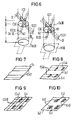
- FIG. 4 shows the principle of matrix addressing selected measuring points of the device shown in Figure 3 in a highly simplified schematic representation.
- the top view shows 6x6 gas discharge channels Gk20, which are traversed by the associated electrode collecting lines ES20 and ES21.
- measuring points M200 and M201 are activated in the manner described in FIG. 1. In this control, which is only indicated by arrows in FIG.
- the matrix addressing described above with reference to FIG. 4 only fails if the same first electrode bus line ES21 or the same second electrode bus line ES20 is assigned to the selected measuring points or gas discharge channels Gk20. This case is shown in FIG. 4 by measuring points M202 and M203, which are to be connected to one another by a dashed line Lb201 and to which the same first electrode bus line ES21 is assigned. The matrix addressing of these measuring points M202 and M203 or the testing of the conductor track Lb201 is shown in FIG. 5.
- a second device which has been appropriately designed from the outset can also be used to record all measuring points.
- FIG. 6 shows a highly simplified schematic illustration of a first variant of the arrangement of the first and second electrodes of the gas discharge channels. Only the contour of the gas discharge channels Gk30 introduced into a carrier plate composed of two layers can be seen.
- the first electrode collecting lines ES31 which form the first electrodes E31, run in a groove N1.
- the second electrode collecting lines ES30 which form the second electrodes E30, run in a groove N2.
- the distance a between the l first electrode bus lines ES30 and the second electrode bus lines ES31, which intersect at an angle of 45 °, is defined by electrically insulating glass fibers Gf, which is also in the grooves N1 are laid.
- the ratio of the distance a between a first electrode E31 and a second electrode E30 to the distance d between a second electrode E30 and an associated measuring point M30 is so small that no gas discharges can ignite between the first electrodes E31 and the second electrodes E30. This is guaranteed with certainty if the ratio a: d is at least 1:10.
- Figures 7 to 10 show different stages of the process for the arrangement of the first and second electrodes according to a second variant.
- conductor tracks using thick-film technology are first applied to a substrate Su made of glass, these conductor tracks forming parallel first electrode collecting lines ES41.
- a first insulating layer Isl is then applied over the entire surface, which only in the form of windows does not cover those areas of the first electrode collecting lines ES41 which form the first electrodes E41.
- further conductor tracks are then applied to the first insulating layer Isl using thick-film technology, these conductor tracks forming parallel second electrode collecting lines ES40 and crossing the first electrode collecting lines ES41 at an angle of 45 °.
- a second insulating layer Is2 is then applied again over the entire area, which merely in the form of windows does not cover the first electrodes E41 and those regions of the second electrode collecting lines ES40 which form the second electrodes E40.
- FIG. 10 shows, only the first electrodes E41 and the second electrodes E40 are then exposed, while the entire remaining area is exposed by the second insulating layer Is2 is covered.
- the substrate Su printed in this way then only needs to be placed upside down on a carrier plate, into which gas discharge channels are introduced as through holes in a corresponding grid.
- a first electrode E41 and a second electrode E40 are then located closely next to one another and electrically insulated from one another at the upper end of each gas discharge channel.
- the grid dimension of the measuring points and thus also of the gas discharge channels Gk20 is, for example, 1/40 ", ie approximately 0.6 mm.
- the diameter of the gas discharge channels Gk20 is then 0.3 mm and that is approximately the thickness of the whole Support ') latte Tp20 corresponding distance e between the first electrodes E21 and the assigned measuring points 0.5 mm.
- the entire arrangement is at a reduced pressure p of about 10 Torr in a nitrogen atmosphere.
- Gas discharge channels Gk20 leading second electrode collecting lines ES20 a voltage is applied which is at least twice the burner voltage corresponds and is, for example, 650 volts.
Abstract
Description
Die Erfindung betrifft eine Vorrichtung für die elektrische Funktionsprüfung von Verdrahtungsfeldern, insbesondere von Leiterplatten, nach dem Oberbegriff des Anspruchs 1.The invention relates to a device for the electrical functional test of wiring fields, in particular of printed circuit boards, according to the preamble of claim 1.
In Prüfautomaten und Prüfadaptern für unbestückte und bestückte Leiterplatten sowie für Verdrahtungsfelder in Löt- oder Crimptechnik wird die Kontaktierung der ausgewählten Meßstellen in der Regel über federnde Prüfspitzen vorgenommen. Die entsprechend dem Rastermaß eines zu prüfenden Verdrahtungsfeldes angeordneten federnden Prüfspitzen werden mittels Federhülsen befestigt, die in eine Trägerplatte eingepreßt sind und in die man die Prüfspitzen einschiebt. Bei der Auswahl der Prüfspitzen entscheiden üblicherweise der kleinste Abstand der Meßstellen zueinander sowie die Strombelastung über den Durchmesser der federnden Prüfspitzen, wobei als unteres Grenzmaß für den Durchmesser jedoch 0,69 mm genannt werden (Elektronik Produktion & Prüftechnik, November 1979, Seiten 472 und 473).In automatic test machines and test adapters for bare and populated printed circuit boards and for wiring fields in soldering or crimping technology, the contacting of the selected measuring points is usually carried out via resilient test probes. The resilient test probes arranged in accordance with the grid dimension of a wiring field to be tested are fastened by means of spring sleeves which are pressed into a carrier plate and into which the test probes are inserted. When selecting the test probes, the smallest distance between the measuring points and the current load usually determine the diameter of the resilient test probes, although 0.69 mm is mentioned as the lower limit for the diameter (Elektronik Produktion & Prüftechnik, November 1979, pages 472 and 473 ).
Mit den bekannten Vorrichtungen für die elektrische Funktionsprüfung von Leiterplatten werden zwischen den durch Rasterpunkte entsprechend dem Layout gebildeten Prüfstellen Leitfähigkeit- und Isolationsmessungen durchgeführt. Da die für die Ankontaktierung der Prüfstellen vorgesehenen federnden Prüfspitzen im Raster de-Leiterplatte angeordnet werden müssen, stößt die Realisierung derartiger Vorrichtungen bei abnehmendem Rastermaß und größer werdenden Flächen der Leiterplatten zunehmend auf prinzipielle Schwierigkeiten. So ist eine Anordnung der federnden Prüfspitzen in Rastermaßen unter einem Millimeter bei einer sicheren mechanischen Kontaktierung der Prüfstellen feinwerktechnisch kaum mehr beherrschbar. Mit der Anzahl der Meßstellen, die beispielsweise Hunderttausend betragen kann, steigt-auch die Anzahl der erforderlichen Zuleitungen und Schaltelemente, wodurch ein erheblicher gerätetechnischer Aufwand und entsprechend hohe Kosten verursacht werden. Außerdem nimmt mit der Anzahl der Meßstellen auch die Wahrscheinlichkeit einer vollständigen Kontaktierung der Leiterplatten erheblich ab.With the known devices for the electrical functional test of printed circuit boards, conductivity and insulation measurements are carried out between the test points formed by grid points according to the layout. Since the resilient test probes provided for the contacting of the test points have to be arranged in the grid de-printed circuit board, the implementation of such devices comes up with a decreasing grid dimensions and increasing areas of the printed circuit boards due to basic difficulties. An arrangement of the resilient test probes in pitches of less than one millimeter with reliable mechanical contacting of the test points can hardly be mastered with precision engineering. With the number of measuring points, which can be, for example, a hundred thousand, the number of supply lines and switching elements required also increases, which causes considerable expenditure on equipment and correspondingly high costs. In addition, the likelihood of complete contacting of the printed circuit boards also decreases considerably with the number of measuring points.
Aus der EP-A-0 102 565 ist eine Vorrichtung für die elektrische Funktionsprüfung von Verdrahtungsfeldern bekannt, bei welcher die bisher übliche ohmische Kontaktierung der Meßstellen durch eine berührungslose ionische Kontaktierung über Gasentladungsstrecken ersetzt wird. Hierzu wird in eine auf die Verdrahtungsfelder aufsetzbare Trägerplatte eine Vielzahl von mit Elektroden versehenen Gasentladungskanälen eingebracht, wobei die im Raster der Verdrahtungsfelder angeordneten Gasentladungskanäle zu den Meßstellen hin offen sind. Sind nun zwei ausgewählte Meßstellen beispielsweise durch eine Leiterbahn elektrisch leitend miteinander verbunden, so bilden die zugeordneten Gasentladungskanäle zwei in Reihe geschaltete Gasentladungsstrecken, die durch Anlegen einer hinreichend hohen Spannung an die Elektroden gezündet werden können. Mit der Zündung der Gasentladungen erfolgt dann ein Stromtransport, der zu Prüfzwecken ausgewertet werden kann. Unterbleibt die Zündung der Gasentladungen oder fließt nach einer Zündung ein zu geringer Strom, so kann auf eine unterbrochene oder von vorneherein nicht existierende elektrisch leitende Verbindung zwischen den ausgewählten Meßstellen geschlossen werden. Wird der an die Elektroden angelegten Spannung eine Wechselspannung überlagert, so kann die daraus resultierende Stromänderung phasenempfindlich zur angelegten Wechselspannung gemessen und für die Bestimmung des Widerstandes einer zwischen den ausgewählten Meßstellen bestehenden Verbindung herangezogen werden. Die bekannte Vorrichtung ermöglicht also Leitfähigkeits- und Isolationsmessungen, wobei durch das Vermeiden von ohmischen Kontakten eine sehr hohe Zuverlässigkeit erreicht wird. Durch das Prinzip der ionischen Kontaktierung der Meßstellen über in äußerst geringen Abmessungen realisierbare Gasentladungskanäle können dann insbesondere auch Verdrahtungsfelder mit kleinen Rastermaßen der Meßstellen bis herab zu 0,1 mm zuverlässig geprüft werden. Bei einer hohen Anzahl der Meßstellen eines zu prüfenden Verdrahtungsfeldes treten jedoch nach wie vor Probleme auf, die durch die zahlreichen Zuleitungen und Schaltelemente für den Anschluß der Elektroden der Gasentladungskanäle zurückzuführen sind.From EP-A-0102565 a device for the electrical functional testing of wiring panels is known, in which the hitherto usual ohm i cal contact between the measuring points is replaced by a non-contact ionic contacting via gas discharge sections. For this purpose, a plurality of gas discharge channels provided with electrodes are placed in a carrier plate which can be placed on the wiring fields, the gas discharge channels arranged in the grid of the wiring fields being open to the measuring points. If two selected measuring points are now connected to one another in an electrically conductive manner, for example by means of a conductor track, the associated gas discharge channels form two gas discharge paths which are connected in series and can be ignited by applying a sufficiently high voltage to the electrodes. When the gas discharges are ignited, electricity is then transported, which can be evaluated for test purposes. If the ignition of the gas discharges does not take place or if too little current flows after an ignition, then an interrupted or non-existent electrically conductive connection between the selected measurements can be made places to be closed. If an alternating voltage is superimposed on the voltage applied to the electrodes, the resulting change in current can be measured in a phase-sensitive manner to the applied alternating voltage and can be used to determine the resistance of a connection existing between the selected measuring points. Thus, the known device enables conductivity and insulation measurements, where very high reliability is achieved by avoiding ohm i rule contacts. Due to the principle of ionic contacting of the measuring points via gas discharge channels that can be realized in extremely small dimensions, wiring fields with small pitches of the measuring points down to 0.1 mm can be reliably tested. With a large number of measuring points of a wiring field to be tested, however, problems still arise which can be attributed to the numerous supply lines and switching elements for connecting the electrodes of the gas discharge channels.
Der Erfindung liegt die Aufgabe zugrunde, bei einer Vorrichtung der eingangs genannten Art die Anzahl der Zuleitungen drastisch zu reduzieren.The invention has for its object to drastically reduce the number of leads in a device of the type mentioned.
Diese Aufgabe wird erfindungsgemäß durch die kennzeichnenden Merkmale des Anspruchs 1 gelöst.This object is achieved by the characterizing features of claim 1.
Der Erfindung liegt die Erkenntnis zugrunde, daß jeder Gasentladungskanal mit mindestens zwei Elektroden bestückt werden kann, wobei die Ansteuerung einer Elektrode allein noch kein Zünden und Brennen von Gasentladungen hervorruft, die Ansteuerung sämtlicher Elektroden jedoch für ein sicheres Zünden und Brennen von Gasentladungen ausreicht. Durch eine derartige Auswahl und Ansteuerung der Gasentladungskanäle nach dem Koinzidenzprinzip werden die Voraussetzungen für eine Matrixadressierung der Meßstellen geschaffen, die mit der Adressierung der einzelnen Kerne eines Kernspeichers vergleichbar ist. Dementsprechend kann dann auch die Auswahl der den Meßstellen zugeordneten Gasentladungskanäle über entsprechende Elektroden-Sammelleitungen vorgenommen werden, wodurch gegenüber der direkten Ansteuerung eines jeden Gasentladungskanals der für die Ansteuerung erforderliche Aufwand ganz erheblich reduziert werden kann.The invention is based on the knowledge that each gas discharge channel can be equipped with at least two electrodes, the activation of one electrode alone not causing ignition and burning of gas discharges, but the activation of all electrodes is sufficient for reliable ignition and burning of gas discharges. Through such a selection and control of the gas discharge channels according to the principle of coincidence, the requirements for a matrix address are met sation of the measuring points created, which is comparable to the addressing of the individual cores of a core memory. Accordingly, the selection of the gas discharge channels assigned to the measuring points can then also be made via corresponding electrode collecting lines, as a result of which the effort required for the control can be considerably reduced compared to the direct activation of each gas discharge channel.
Die Auswahl eines mit vorzugsweise zwei Elektroden ausgerüsteten Gasentladungskanals nach dem Koinzidenzprinzip über zwei Elektroden-Sammelleitungen kann grundsätzlich darauf beruhen, daß das Zünden und/oder Brennen einer Gasentladung erst durch das Zusammenwirken beider Elektroden ermöglicht wird oder daß das Zünden und/oder Brennen einer Gasentladung durch eine der Elektroden verhindert wird, wobei diese Hemmwirkung durch eine Ansteuerung dieser Elektrode aufgehoben wird.The selection of a gas discharge channel equipped with preferably two electrodes according to the principle of coincidence via two electrode collecting lines can in principle be based on the fact that the ignition and / or burning of a gas discharge is only made possible by the interaction of both electrodes or that the ignition and / or burning of a gas discharge is possible one of the electrodes is prevented, this inhibitory effect being eliminated by activating this electrode.
Bei der erfindungsgemäßen Vorrichtung für die elektrische Funktionsprüfung von Verdrahtungsfeldern werden die Meßstellen vorzugsweise ionisch kontaktiert, d.h. eine Elektrode der Gasentladungsstrecken wird unmittelbar durch die Meßstellen auf der Leiterplatte gebildet. Durch das Vermeiden von ohm!schen Kontakten wird dabei eine sehr hohe Zuverlässigkeit erreicht. Die Vorteile der erfindungsgemäßen Adressierung, insbesondere Matrixadressierung von Meßstellen bzw. Gasentladungskanälen mit einer erheblichen Reduzierung des Verdrahtungsaufwands ergeben sich jedoch auch dann, wenn eine ohm'sche Kontaktierung der Meßstellen durch am unteren Ende der Gasentladungskanäle angeordnete federnde Prüfspitzen vorgenommen wird. Diese federnden Prüfspitzen bilden dann eine weitere Elektrode der Gasentladungskanäle, d.h. sie werden an dem der Spitze gegenüberliegenden Ende ionisch kontaktiert und können mit geringeren Durchmessern realisiert werden als die mit einer Verdrahtung verbundenen herkömmlichen Prüfspitzen. Die geringen Rasterabmessungen bei einer ionischen Kontaktierung mit zu den Meßstellen hin offenen Gasentladungskanälen können mit Prüfspitzen jedoch nicht erreicht werden.In the device according to the invention for the electrical functional test of wiring fields, the measuring points are preferably contacted ionically, ie an electrode of the gas discharge paths is formed directly by the measuring points on the circuit board. By avoiding ohmic contacts, a very high level of reliability is achieved. However, the advantages of the addressing according to the invention, in particular matrix addressing of measuring points or gas discharge channels with a considerable reduction in the amount of wiring, also result if the measuring points are made ohmic contact by resilient test probes arranged at the lower end of the gas discharge channels. These resilient test tips then form a further electrode of the gas discharge channels, ie they are contacted ionically at the end opposite the tip and can have fewer Diameters can be realized as the conventional test probes connected with wiring. However, the small grid dimensions in the case of ionic contacting with gas discharge channels open to the measuring points cannot be achieved with test probes.
Gemäß einer bevorzugten Ausgestaltung der Erfindung ist vorgesehen, daß erste Elektroden der Gasentladungskanäle reihenweise über erste Elektroden-Sammelleitungen miteinander verbunden sind und daß zweite Elektroden der Gasentladungskanäle reihenweise über zweite Elektroden-Sammelleitungen miteinander verbunden sind. Bei einer derartigen Ausbildung, die insbesondere für Leiterplatten mit einer Anordnung der Meßstellen in einem regelmäßigen Raster geeignet ist, ergibt sich eine besonders einfache und übersichtliche Verlegung der Elektroden-Sammelleitungen. Außerdem entspricht die reihenweise Zusammenfassung der Elektroden dem Idealfall einer Matrixadressierung der Meßstellen.According to a preferred embodiment of the invention, it is provided that first electrodes of the gas discharge channels are connected to one another in rows via first electrode collecting lines and that second electrodes of the gas discharge channels are connected to one another in rows via second electrode collecting lines. Such a design, which is particularly suitable for printed circuit boards with an arrangement of the measuring points in a regular grid, results in a particularly simple and clear laying of the electrode collecting lines. In addition, the row-by-row combination of the electrodes corresponds to the ideal case of matrix addressing of the measuring points.
Weiterhin ist es besonders vorteilhaft, wenn die ersten und die zweiten Elektroden in verschiedenen Höhenlagen der Gasentladungskanäle angeordnet sind. Eine der Elektroden kann dann die Aufgabe eines Gitters übernehmen, mit welchem die Zündung einer Gasentladung besonders zuverlässig gesteuert, d.h. verhindert oder eingeleitet werden kann.Furthermore, it is particularly advantageous if the first and the second electrodes are arranged at different heights of the gas discharge channels. One of the electrodes can then take on the task of a grid with which the ignition of a gas discharge is controlled in a particularly reliable manner, i.e. can be prevented or initiated.
Es ist aber auch möglich, die zweiten Elektroden mit einem elektrisch isolierenden Material zu umhüllen.However, it is also possible to coat the second electrodes with an electrically insulating material.
Diese zweiten Elektrcden können dann mit Spannungsimpulsen beschickt werden, welche als Zündimpulse die Zündung von Gasentladungen bewirken. Im übrigen üben derartige mit einer Isolierung versehene Elektroden keinen merklichen Einfluß auf die Gasentladungsstrecken aus.These second electrodes can then be charged with voltage pulses which, as ignition pulses, cause the ignition of gas discharges. Otherwise, such electrodes provided with insulation have no noticeable influence on the gas discharge paths.
Eine weitere Reduzierung des Verdrahtungsaufwands ergibt sich, wenn die Elektroden durch die Gasentladungskanäle überquerende Abschnitte der Elektroden-Sammelleitungen gebildet sind.A further reduction in the wiring effort results if the electrodes are formed by sections of the electrode collecting lines crossing the gas discharge channels.
Es ist auch besonders günstig, wenn die ersten Elektroden-Sammelleitungen und die zweiten Elektroden-Sammelleitungen sich.kreuzend angeordnet sind, wobei sie sich vorzugsweise unter einem Winkel von 45° kreuzen. Durch diese Maßnahme wird dem Umstand Rechnung getragen, daß zwei ausgewählte Meßstellen nicht über eine gemeinsame Elektroden-Sammelleitung adressiert werden können. Bei einer sich kreuzenden Anordnung der Elektroden-Sammelleitung können dann durch eine Verdrehung der gesamten Trägerplatte um einen Winkel von 90° oder 2700 relativ zur Verdrahtung sämtliche Meßstellen sicher erfaßt werden.It is also particularly expedient if the first electrode collecting lines and the second electrode collecting lines are arranged crossing one another, preferably crossing at an angle of 45 °. This measure takes into account the fact that two selected measuring points cannot be addressed via a common electrode bus. In an intersecting arrangement of the electrode bus line can then be safely detected by a rotation of the entire support plate by an angle of 90 ° or 270 0 relative to the wiring all measuring points.
Ist der Abstand zwischen der ersten Elektrode und der zweiten Elektrode eines Gasentladungskanals klein im Verhältnis zum Abstand zwischen der zweiten Elektrode und einer zugeordneten Meßstelle, so wird die Sicherheit und Zuverlässigkeit der Vorrichtung weiter erhöht. Bei einem geringen Abstand zwischen der ersten und der zweiten Elektrode findet keine Ionisierung statt oder es entstehen so wenig Ionen, daß eine unerwünschte Gasentladung zwischen der ersten und zweiten Elektrode nicht zünden kann. Im Hinblick darauf hat es sich als besonders günstig erwiesen, wenn das Verhältnis des Abstandes zwischen der ersten Elektrode und der zweiten Elektrode zum Abstand zwischen der zweiten Elektrode und der zugeordneten Meßstelle mindestens 1 : 10 beträge.If the distance between the first electrode and the second electrode of a gas discharge channel is small in relation to the distance between the second electrode and an assigned measuring point, the safety and reliability of the device is further increased. If the distance between the first and second electrodes is small, no ionization takes place or so few ions are generated that an undesired gas discharge between the first and second electrodes cannot ignite. In this regard, it has proven to be particularly advantageous if the ratio of the distance between the first electrode and the second electrode to the distance between the second electrode and the assigned measuring point is at least 1:10.
Ist zwischen der ersten Elektrode und der zweiten Elektrode eines Gasentladungskanals ein elektrischer Isolator angeordnet, so wird die Wahrscheinlichkeit der Zündung einer Gasentladung zwischen beiden Elektroden weiter herabgesetzt. Außerdem kann dann der Abstand zwischen beiden Elektroden besonders gering bemessen werden.If an electrical insulator is arranged between the first electrode and the second electrode of a gas discharge channel, the probability of ignition becomes a gas discharge between the two electrodes is further reduced. In addition, the distance between the two electrodes can then be made particularly small.
Sind die Elektroden-Sammelleitungen bandförmig ausgebildet, so kann ihre Herstellung und Verlegung mit auf dem Gebiet der Schaltungstechnik bewährten Methoden weiter vereinfacht werden. Insbesondere können dann die Elektroden-Sammelleitungen durch die Leiterbahnen einer Schichtschaltung gebildet werden.If the electrode collecting lines are in the form of a band, their manufacture and laying can be further simplified using methods which have been tried and tested in the field of circuit technology. In particular, the electrode collecting lines can then be formed by the conductor tracks of a layer circuit.
Eine besonders hohe Funktionssicherheit wird erreicht, wenn an die ersten Elektroden zweiter ausgewählter Gasentladungskanäle über die zugeordneten ersten Elektroden-Sammelleitungen eine Spannung anlegbar ist, welche zumindest der doppelten Zündspannung einer Gasentladungsstrecke entspricht und wenn an die zweiten Elektroden der beiden Gasentladungskanäle über die zugeordneten zweiten Elektroden-Sammelleitungen eine derartige Spannung anlegbar ist, durch welche eine Zündung der Gasentladungsstrecken einleitbar ist. Bei einer derartigen Anordnung liegen sämtliche nicht angesteuerten zweiten Elektroden auf dem gleichen Potential, d.h. es entsteht eine Art Potentialschirm, der die unerwünschte Zündung von 'Gasentladungen in nicht ausgewählten Gasentladungskanälen verhindert.A particularly high level of functional reliability is achieved if a voltage can be applied to the first electrodes of second selected gas discharge channels via the assigned first electrode collecting lines, which voltage corresponds to at least twice the ignition voltage of a gas discharge path and if the second electrodes of the two gas discharge channels are connected via the assigned second electrode Such lines can be applied to the collecting lines, by means of which ignition of the gas discharge paths can be initiated. With such an arrangement, all of the second electrodes which are not driven are at the same potential, i.e. a kind of potential shield is created which prevents the undesired ignition of gas discharges in unselected gas discharge channels.
Dabei ist es dann zweckmäßig, wenn mit Ausnahme der zu den zweiten Elektroden ausgewählter Gasentladungskanäle führenden zweiten Elektroden-Sammelleitungen sämtliche zweiten Elektroden-Sammelleitungen miteinander verbindbar sind. Durch diese Maßnahme ist die Bildung eines Potentialschirms durch die zweiten Elektroden auch dann gewährleistet, wenn sich nicht sämtliche Elektroden-Sammelleitungen kreuzen. Insbesondere können dann die Abmessungen der Trägerplatte auf die Abmessungen einer zu prüfenden Leiterplatte genau abgestimmt werden. Zur weiteren Steigerung der Funktionsssicherheit können dann auch zusätzlich noch die miteinander verbundenen zweiten Elektroden-Sammelleitungen an ein Potential angeschlossen werden, welches eine Zündung der Gasentladungsstrekken verhindert.It is then expedient if, with the exception of the second electrode collecting lines leading to the second electrodes of selected gas discharge channels, all of the second electrode collecting lines can be connected to one another. This measure ensures the formation of a potential shield by the second electrodes even if not all of the electrode collecting lines intersect. In particular, the dimensions of the carrier plate can then be adapted to the dimensions of a testing PCB can be precisely matched. To further increase the functional reliability, the interconnected second electrode collecting lines can also be connected to a potential which prevents the gas discharge lines from igniting.
Schließlich können auch noch sämtliche Gasentladungskanäle mit einer ionisierenden Strahlung beaufschlagt werden. Durch eine derarige Beaufschlagung mit einer ionisierenden Strahlung, beispielsweise mit einer UV-Strahlung, werden Zündverzögerungen vermieden, d.h. die Sicherheit und die Geschwindigkeit einer elektrischen Funktionsprüfung können weiter gesteigert werden.Finally, all gas discharge channels can also be exposed to ionizing radiation. Such exposure to ionizing radiation, for example UV radiation, avoids ignition delays, i.e. the safety and speed of an electrical functional test can be further increased.
Ausführungsbeispiele der Erfindung sind in der Zeichnung dargestellt und werden im folgenden näher beschrieben.Embodiments of the invention are shown in the drawing and are described in more detail below.
Es zeigen
- Figur 1 das Prinzip einer erfindungsgemäßen Vorrichtung für die elektrische Funktionsprüfung von Leiterplatten,
Figur 2 eine Variante des in Figur 1 gezeigten Prinzips,Figur 3 die Ausgestaltung einer Trägerplatte mit Gasentladungskanälen, Elektroden und Elektroden-Sammelleitungen,- Figur 4 das Prinzip der Matrixadressierung ausgewählter Meßstellen bei der in
Figur 3 dargestellten Trägerplatte, - Figur 5 das Prinzip der Matrixadressierung bei einer gegenüber der Darstellung in Figur 4 um einen Winkel von 90° verdrehten Anordnung der Trägerplatte,
- Figur 6 eine erste Variante der Anordnung der Elektroden der Gasentladungskanäle und die
- Figuren 7 bis 10 verschiedene Verfahrensstadien für die Anordnung der Elektroden der Gasentladungskanäle gemäß einer zweiten Variante.
- FIG. 1 shows the principle of a device according to the invention for the electrical functional test of printed circuit boards,
- FIG. 2 shows a variant of the principle shown in FIG. 1,
- FIG. 3 shows the design of a carrier plate with gas discharge channels, electrodes and electrode collecting lines,
- FIG. 4 shows the principle of matrix addressing of selected measuring points in the carrier plate shown in FIG. 3,
- FIG. 5 shows the principle of matrix addressing in the case of an arrangement of the carrier plate rotated by an angle of 90 ° compared to the illustration in FIG. 4,
- Figure 6 shows a first variant of the arrangement of the electrodes of the gas discharge channels and the
- Figures 7 to 10 different process stages for the arrangement of the electrodes of the gas discharge channels according to a second variant.
Figur 1 zeigt in stark vereinfachter schematischer Darstellung die Wirkungsweise einer Vorrichtung für die elektrische Funktionsprüfung von Leiterplatten auf der Basis einer berührungslosen ionischen Kontaktierung.der Meßstellen über Gasentladungsstrecken. Es ist ein Teil einer mit Lpl bezeichneten Leiterplatte zu erkennen, auf deren Oberseite die Enden einer Leiterbahn Lbl Meßstellen M1 und M2 bilden. Auf die Oberseite der Leiterplatte Lpl ist eine Trägerplatte Tpl aus einem isolierenden Material wie z.B. Glas aufgesetzt, in welche in Form von Sacklöchern eine Vielzahl von Gasentladungskanälen eingebracht ist. In der Zeichnung sind dabei nur der der Meßstelle Ml zugeordnete Gasentladungskanal Gkl und der der Meßstelle M2 zugeordnete Gasentladungskanal Gk2 dargestellt. Auf der der Meßstelle M1 gegenüberliegenden Seite des Gasentladungskanals Gkl sind Elektroden El und E2 angeordnet, wobei die Elektrode E2 etwas tiefer liegt als die Elektrode El. Dabei sind die Elektrode E1 an eine Elektroden-Sammelleitung ES1 und die Elektrode E2 an eine Elektroden-Sammelleitung ES2 angeschlossen. In entsprechender Weise sind auf der der Meßstelle M2 gegenüberliegenden Seite des Gasentladungskanals Gk2 Elektroden E3 und E4 angeordnet, wobei die Elektrode E4 wieder etwas tiefer, d.h. auf gleicher Hohe mit der Elektrode E2 liegt. Die Elektrode E3 ist an eine Elektroden-Sammelleitung ES3 angeschlossen, während die Elektrode E4 an eine Elektroden-Sammelleitung ES4 angeschlossen ist. Über die Elektroden-Sammelleitungen ES1, ES2, ES3 und ES4 sind dabei jeweils die Elektroden einer Vielzahl von in Figur 1 nicht dargestellten Gasentladungskanälen reihenweise miteinander verbunden. Werden nun bei der elektrischen Funktionsprüfung der Leiterplatte Lpl die beiden Meßstellen Ml und M2 ausgewählt, so werden die ersten Elektroden El und E3 der zugeordneten Gasentladungskanäle Gkl und Gk2 über die ersten Elektroden-Sammelleitungen ES1 und ES3 angesteuert, wobei diese Ansteuerung durch Schalter Sl und S3 aufgezeigt ist. Zwischen den Schaltern Sl und S3 sind nacheinander in Reihe eine Spannungsquelle Sql, ein Vorwiderstand Vwl, ein Strommeßgerät Sm und ein Wechselspannungserzeuger We angeordnet.Figure 1 shows a highly simplified schematic representation of the operation of a device for the electrical functional test of printed circuit boards on the basis of a non-contact ionic contact. Of the measuring points over gas discharge paths. A part of a circuit board labeled Lpl can be seen, on the upper side of which the ends of a conductor track Lbl form measuring points M1 and M2. A carrier plate Tpl made of an insulating material, such as glass, is placed on the top of the printed circuit board Lpl, and a plurality of gas discharge channels are introduced in the form of blind holes. In the drawing, only the gas discharge channel Gkl assigned to the measuring point M1 and the gas discharge channel Gk2 assigned to the measuring point M2 are shown. Electrodes E1 and E2 are arranged on the side of the gas discharge channel Gkl opposite the measuring point M1, the electrode E2 being somewhat lower than the electrode El. The electrode E1 is connected to an electrode manifold ES1 and the electrode E2 to an electrode manifold ES2. In a corresponding manner, electrodes E3 and E4 are arranged on the side of the gas discharge channel Gk2 opposite the measuring point M2, the electrode E4 again being somewhat lower, ie at the same height as the electrode E2. The electrode E3 is connected to an electrode collecting line ES3, while the electrode E4 is connected to an electrode collecting line ES4. The electrodes of a multiplicity of gas discharge channels (not shown in FIG. 1) are each connected in rows to one another via the electrode collecting lines ES1, ES2, ES3 and ES4. If the two measuring points M1 and M2 are now selected during the electrical functional test of the printed circuit board Lpl, the first electrodes El and E3 of the associated gas discharge channels Gkl and Gk2 are activated via the first electrode collecting lines ES1 and ES3, this activation being performed by switches S1 and S3 is shown. A voltage source Sql, a series resistor Vwl, a current measuring device Sm and an AC voltage generator We are arranged in series between the switches S1 and S3.
Die vorstehend beschriebene Ansteuerung der ersten Elektroden El und E3 reicht für eine eindeutige Auswahl der Meßstellen Ml und M2 noch nicht aus. Um diese eindeutige Auswahl zu gewährleisten, werden nach dem Koinzidenzprinzip gleichzeitig die zweiten Elektroden E2 und E4 der zugeordneten Gasentladungskanäle Gkl und Gk2 über die Elektroden-Sammelleitungen ES2 und ES4 angesteuert, wobei diese Ansteuerung durch Schalter S2 und S4 aufgezeigt ist. Im nicht angesteuerten Zustand der zweiten Elektroden E2 und E4 sind diese zweiten Elektroden E2 und E4 bei der dargestellten Stellung der-Schalter S2 und S4 miteinander verbunden und an ein Potential P = Uz angeschlossen. An dieses Potential P sind im übrigen alle diejenigen zweiten Elektroden angeschlossen, die. nicht über zugeordnete zweite Elektroden-Sammelleitungen angeschlossen sind. In der anderen, nicht dargestellten Stellung sind zwischen den Schaltern S2 und S4 nacheinander in Reihe eine Spannungsquelle Sq2 und ein Vorwiderstand Vw2 angeordnet.The activation of the first electrodes E1 and E3 described above is not sufficient for a clear selection of the measuring points M1 and M2. In order to ensure this unambiguous selection, the second electrodes E2 and E4 of the associated gas discharge channels Gkl and Gk2 are simultaneously controlled via the electrode collecting lines ES2 and ES4, according to the principle of coincidence, this control being indicated by switches S2 and S4. In the non-activated state of the second electrodes E2 and E4, these second electrodes E2 and E4 are connected to one another in the illustrated position of the switches S2 and S4 and connected to a potential P = Uz. All those second electrodes are connected to this potential P, which. are not connected via assigned second electrode collecting lines. In the other position, not shown, a voltage source Sq2 and a series resistor Vw2 are arranged in series between the switches S2 and S4.
Die gesamte in Figur 1 dargestellte Anordnung befindet sich in einem evakuierbaren Raum unter einem verminderten Druck von beispielsweise 10 Torr, wobei der evakuierbare Raum mit einem Gas wie z.B. Stickstoff gefüllt ist. Somit sind zwischen der ersten Elektrode El und der Meßstelle Ml sowie zwischen der ersten Elektrode E3 und der Meßstelle M2 Gasentladungsstrecken gebildet, die über die Leiterbahn Lbl in Reihe geschaltet sind. Die Spannung der Spannungsquelle Sql ist nun derart bemessen, daß an diese beiden in Reihe geschalteten Gasentladungsstrecken über die Schalter Sl und S3 zumindest die doppelte Zündspannung Uz einer Gasentladungsstrecke angelegt ist. Dabei ist der ersten Elektrode El das Potential P = o zugeordnet, während der ersten Elektrode E3 das Potential P = 2 Uz der Spannungsquelle Sql zugeordnet ist. Obwohl an den ersten Elektroden El und E3 die doppelte Zündspannung Uz anliegt, kommt es dadurch allein noch zu keiner Zündung der in Reihe geschalteten Gasentladungsstrecken. Eine derartige Zündung wird durch die zweiten Elektroden E2 und E4 verhindert, die im nicht angesteuerten Zustand einen Potentialschirm bilden und im dargestellten Ausführungsbeispiel auf dem Potential P = Uz liegen. Erst im angesteuerten Zustand liegen die Elektroden E2 und E4 auf einem Potential, bei welchem eine Zündung der Gasentladungsstrecken über die ersten Elektroden El und E3 erfolgen kann. Bei der Ansteuerung über die Schalter S2 und S4 wird an die zweiten Elektroden E2 und E4 eine Spannung angelegt, welche beispielsweise der doppelten Brennspannung Ub einer Gaseritladungsstrecke entspricht. Dabei ist der zweiten Elektrode E2 das Potential P = o zugeordnet, während der zweiten Elektrode E4 das Potential P = 2 Ub der Spannungsquelle Sq2 zugeordnet ist.The entire arrangement shown in FIG. 1 is located in an evacuable space under a reduced pressure of, for example, 10 torr, the evacuable space being filled with a gas such as nitrogen. Thus there are between the first electrode El and the measuring place Ml and between the first electrode E3 and the measuring point M2 gas discharge paths are formed, which are connected in series via the conductor track Lbl. The voltage of the voltage source Sql is now dimensioned such that at least twice the ignition voltage Uz of a gas discharge line is applied to these two gas discharge lines connected in series via the switches S1 and S3. The potential P = o is assigned to the first electrode El, while the potential P = 2 Uz of the voltage source Sql is assigned to the first electrode E3. Although double the ignition voltage Uz is present at the first electrodes E1 and E3, this alone does not result in the gas discharge paths connected in series being ignited. Such an ignition is prevented by the second electrodes E2 and E4, which form a potential shield in the non-activated state and are at the potential P = Uz in the exemplary embodiment shown. Only in the activated state are the electrodes E2 and E4 at a potential at which the gas discharge paths can be ignited via the first electrodes E1 and E3. When actuated via the switches S2 and S4, a voltage is applied to the second electrodes E2 and E4 which corresponds, for example, to twice the operating voltage Ub of a gasite charge path. The potential P = o is assigned to the second electrode E2, while the potential P = 2 Ub of the voltage source Sq2 is assigned to the second electrode E4.
Werden die erste Elektrode El über die erste Elektroden- Sammelleitung ES1, die zweite Elektrode E2 über die zweite Elektroden-Sammelleitung ES2, die erste Elektrode E3 über die erste Elektroden-Sammelleitung ES3 und die zweite Elektrode E4 über die zweite Elektroden-Sammelleitung ES4 nach dem Koinzidenzprinzip angesteuert, so werden in den ausgewählten Gasentladungskanälen Gkl und Gk2 Gasentladungen gezündet, sofern die beiden Meßstellen Ml und M2 elektrisch hinreichend leitend miteinander verbunden sind. Die einmal gezündeten Gasentladungen können dann über die zweiten als Gitter wirkenden Elektroden E2 und E4 nicht mehr beeinflußt werden. Das Brennen der beiden Gasentladungen kann dabei über das in den Stromkreis eingeschaltete Strommeßgerät Sm registriert werden. Unterbleibt die Zündung oder fließt nach einer Zündung ein zu geringer Strom, so kann auf eine Unterbrechung der Leiterbahn Lbl oder auf eine von vorneherein nicht existierende elektrisch leitende Verbindung zwischen den Meßstellen Ml und M2 geschlossen werden. Für Messungen des Widerstandes zwischen den Meßstellen Ml und M2 wird über den Wechselspannungserzeuger We zusätzlich eine Wechselspannung überlagert, wobei diese Überlagerung wie im dargestellten Ausführungsbeispiel durch induktive Ankoppelung vorgenommen werden kann. Die Widerstandsmessungen werden am differentiellen Umkehrpunkt der Gasentladungscharakteristik vorgenommen, wobei die Innenwiderstände der Gasentfladungsstrecken praktisch wechselstrommäßig überbrückt werden. Dabei führen kleine Schwankungen Δ U der überlagerten Wechselspannung zu relativ großen Schwankungen ΔI des Stromes. Das im Stromkreis angeordnete phasenempfindliche Strommeßgerät Sm, bei welchem es sich beispielsweise um einen handelsüblichen lock-in-amplifier handeln kann, registriert die Stromschwankungen ΔI und der Widerstand R kann aus der Beziehung R = ΔU /ΔI ermittelt werden. Aus der Höhe des ermittelten Widerstandes R kann dann ggf. auf Fehler geschlossen werden, bei welchen die Leiterbahn Lbl nur teilweise unterbrochen ist. Außerdem kann die Ermittlung des Widerstandes R auch für Isolationsmessungen herangezogen werden.The first electrode E1 via the first electrode bus line ES1, the second electrode E2 via the second electrode bus line ES2, the first electrode E3 via the first electrode bus line ES3 and the second electrode E4 via the second electrode bus line ES4 after Controlled coincidence principle, so in the selected gas discharge channels Gkl and Gk2 gas discharges ignited, provided that the two measuring points M1 and M2 are connected to one another in an electrically conductive manner. The gas discharges once ignited can then no longer be influenced by the second electrodes E2 and E4, which act as a grid. The burning of the two gas discharges can be registered via the current measuring device Sm which is switched into the circuit. If the ignition fails to occur or if a current which is too low flows after an ignition, it can be concluded that the conductor track Lbl has been interrupted or that there is no electrically conductive connection between the measuring points M1 and M2 from the start. For measurements of the resistance between the measuring points M1 and M2, an alternating voltage is additionally superimposed on the alternating voltage generator We, this superimposition being able to be carried out by inductive coupling, as in the exemplary embodiment shown. The resistance measurements are carried out at the differential reversal point of the gas discharge characteristic, the internal resistances of the gas discharge paths being bridged practically in alternating current. Small fluctuations Δ U of the superimposed AC voltage lead to relatively large fluctuations ΔI of the current. The phase-sensitive current measuring device Sm arranged in the circuit, which can be, for example, a commercially available lock-in amplifier, registers the current fluctuations ΔI and the resistance R can be determined from the relationship R = ΔU / ΔI. From the level of the determined resistance R, errors can then be deduced, in which the conductor track Lbl is only partially interrupted. In addition, the determination of the resistance R can also be used for insulation measurements.
Figur 2 zeigt eine Variante, bei welcher die Trägerplatte mit TplO und die den Meßstellen Ml und M2 zugeordneten Gasentladungskanäle mit Gk 10 und Gkll bezeichnet sind. Die Ansteuerung der ersten Elektroden E10 und E12 erfolgt'in der zuvor beschriebenen Weise über die Schalter Sl und S3 und entsprechende erste Elektroden-Sammelleitungen ES10 bzw. ES12.Die Spannungsquelle Sql ist dabei jedoch auf eine Spannung eingestellt, welche zumindest der doppelten Brennspannung Ub einer Gasentladungsstrecke entspricht, die doppelte Zündspannung Uz aber nicht erreicht. Im dargestellten Ausführungsbeispiel ist der ersten Elektrode E1 das Potential P = o zugeordnet, während der ersten Elektrode E12 das Potential P = 2 Ub zugeordnet ist.Figure 2 shows a variant in which the carrier plate with TplO and the assigned to the measuring points M1 and M2 ten gas discharge channels are designated
Die zweiten mit Ell und E13 bezeichneten Elektroden der Gasentladungskanäle Gk10 bzw. Gkll werden über zugeordnete Elektroden-Sammelleitungen ES10 bzw. ES13 und Schalter S11 bzw. S13 angesteuert. Im angesteuerten Zustand sind die beiden zweiten Elektroden E11 und E13 an einen Impulserzeuger Ie angeschlossen, über welchen zur Zündung von Gasentladungen gleichzeitig eine Beaufschlagung mit Hochspannungs-Impulsen HI entgegengesetzter Polarität vorgenommen werden kann. Im dargestellten Fall wird die zweite Elektrode Ell mit einem negativen Hochspannungs-Impuls HI beaufschlagt, während die zweite Elektrode E13 gleichzeitig mit einem positiven Hochspannungs-Impuls HI beaufschlagt wird. Die Hochspannungs-Impulse HI, die deutlich größer sind als die Zündspannung Uz, können eine sichere Zündung der Gasentladungen auch dann bewirken, wenn die zweiten Elektroden Ell und E13 mit einem elektrisch isolierenden Material M, wie z.B. einer Keramik, umhüllt sind. Andererseits hat die Umhüllung mit dem elektrisch isolierenden Material M den Vorteil, daß die zweiten Elektroden Ell und E13 als reine Zündelektroden wirken und die Gasentladungen sonst nicht beeinflussen.The second electrodes of the gas discharge channels Gk10 and Gkll, denoted by Ell and E13, are controlled via assigned electrode collecting lines ES10 or ES13 and switches S11 and S13. In the activated state, the two second electrodes E11 and E13 are connected to a pulse generator Ie, via which a high-voltage pulse HI of opposite polarity can be applied simultaneously to ignite gas discharges. In the case shown, a negative high-voltage pulse HI is applied to the second electrode Ell, while a positive high-voltage pulse HI is applied to the second electrode E13 at the same time. The high-voltage pulses HI, which are significantly larger than the ignition voltage Uz, can also reliably ignite the gas discharges if the second electrodes Ell and E13 are coated with an electrically insulating material M, e.g. a ceramic, are covered. On the other hand, the covering with the electrically insulating material M has the advantage that the second electrodes E1 and E13 act as pure ignition electrodes and do not otherwise influence the gas discharges.
Figur 3 zeigt in perspektivischer Darstellung einen Teil einer Leiterplatte Lp20, auf deren Oberfläche im Rastermaß angeordnete Meßstellen M20, M21, M22 und M23 sowie -Leiterbahnen Lb20, Lb21, Lb22, Lb23 und Lb24 zu erkennen sind. Die zueinander senkrechten Hauptrichtungen der Leiterbahnen sind mit HR1 und HR2 bezeichnet. Auf die Oberseite der Leiterplatte.Lp20 ist eine insgesamt mit Tp20 bezeichnete Trägerplatte aufgesetzt, in welche eine Vielzahl zylindrischer Gasentladungskanäle Gk20 eingebracht ist. Die aus einer oberen Platte Po und einer unteren Platte Pu zusammengesetzte Trägerplatte Tp20 besteht aus fotolithografisch strukturierbarem Formglas, in welches die Gasentladungskanäle Gk20 mittels üblicher Maskierungs- und Ätztechniken eingebracht werden. In die Oberseite der oberen Platte Po sind ferner geradlinige und in der Hauptrichtung HR2 verlaufende Rillen eingebracht, in welchen erste Elektroden-Sammelleitungen ES21 verlaufen. Die mit E21 bezeichneten ersten Elektroden der Gasentladungskanäle Gk20 sind unmittelbar durch die Gasentladungskanäle Gk20 überquerende Abschnitte der Elektroden-Sammelleitungen ES21 gebildet. In die Unterseite der oberen Platte Po oder in die Oberseite der unteren Platte Pu sind geradlinige und zu den beiden Hauptrichtungen unter einem Winkel von 45° verlaufende Rillen eingebracht, in welchen zweite Elektroden-Sammelleitungen ES20 verlaufen. Die mit E20 bezeichneten zweiten Elektroden der Gasentladungskanäle Gk20 sind unmittelbar durch die Gasentladungskanäle Gk20 überquerende Abschnitte der zweiten Elektroden-Sammelleitungen ES20 gebildet. Die Herstellung der bandförmigen Elektroden-Sammelleitungen ES20 und ES21 mit den zugehörigen Elektroden E20 bzw. E21 kann mit auf dem Gebiet der gedruckten Schaltungen oder Schichtschaltungen üblichen Techniken vorgenommen werden, wobei als Materialien Edelmetalle wie z.B. Gold geeignet sind.FIG. 3 shows a perspective view of a part of a printed circuit board Lp20, on the surface of which measuring points M20, M21, M22 and M23 arranged in grid spacing and conductor tracks Lb20, Lb21, Lb22, Lb23 and Lb24 can be seen. The main directions of the conductor tracks, which are perpendicular to one another, are designated HR1 and HR2. On the top of the PCB.Lp20, a carrier plate, generally designated Tp20, is placed, into which a plurality of cylindrical gas discharge channels Gk20 is introduced. The carrier plate Tp20, which is composed of an upper plate Po and a lower plate Pu, consists of shaped glass which can be structured photolithographically, into which the gas discharge channels Gk20 are introduced by means of conventional masking and etching techniques. In the upper side of the upper plate Po there are also rectilinear grooves which run in the main direction HR2 and in which first electrode collecting lines ES21 run. The first electrodes of the gas discharge channels Gk20, designated E21, are formed directly by sections of the electrode collecting lines ES21 crossing the gas discharge channels Gk20. In the underside of the upper plate Po or in the upper side of the lower plate Pu there are rectilinear grooves which run at an angle of 45 ° to the two main directions and in which second electrode collecting lines ES20 run. The second electrodes of the gas discharge channels Gk20, designated E20, are formed directly by sections of the second electrode collecting lines ES20 crossing the gas discharge channels Gk20. The production of the band-shaped electrode collecting lines ES20 and ES21 with the associated electrodes E20 and E21 can be carried out using techniques customary in the field of printed circuits or layer circuits, the materials used being noble metals such as e.g. Gold are suitable.
Die Lage der Gasentladungskanäle Gk20 entspricht genau dem Raster der Meßstellen einer zu prüfenden Leiterplatte Lp20, wobei in Figur 3 die genaue Zuordnung von in der Schnittebene der Trägerplatte Tp20 liegenden Gasentladungskanälen Gk20 zu den unmittelbar darunter liegenden Meßstellen M20, M21, M22 und M23 deutlich zu erkennen ist. Es ist ferner zu erkennen, daß die Anzahl der in Zeilen und Spalten angeordneten Gasentladungskanäle Gk20 durchaus größer sein kann als die Anzahl der auf der Leiterplatte Lp20 vorhandenen Meßstellen.The position of the gas discharge channels Gk20 corresponds exactly to the grid of the measuring points of a circuit board Lp20 to be tested, with the precise assignment of gas discharge channels Gk20 lying in the sectional plane of the carrier plate Tp20 to the measuring points M20, M21, M22 and M23 located directly underneath being clearly recognizable is. It can also be seen that the number of gas discharge channels Gk20 arranged in rows and columns may well be greater than the number of measuring points present on the circuit board Lp20.
Die Stärke der oberen Platte Po ist in Figur 3 stark übertrieben. In Wirklichkeit ist die Stärke der oberen Platte Po sehr gering im Verhältnis zur Stärke- der unterfn Platte Pu, so daß auch der Abstand zwischen der ersten Elektrode E21 und der zweiten Elektrode E20 eines Gasentladungskanals Gk20 klein ist im Verhältnis zum Abstand zwischen der zweiten Elektrode E20 und einer zugeordneten Meßstelle. Durch diese Bemessung werden unerwünschte Gasentladungen zwischen einer ersten Elektrode E21 und einer zweiten Elektrode E20 sicher verhindert. Um Gasentladungen zwischen benachbarten ersten Elektroden E21 bzw. ersten Elektroden-Sammelleitungen ES21 zu verhindern, wird auf die Oberseite der oberen Platte Po zusätzli-ch noch eine in Figur 3 nicht dargestellte Deckplatte aus isolierendem Material aufgesetzt. Im dargestellten Fall besteht diese Deckplatte aus Glas, sa daß sämtliche Gasentladungskanäle Gk20 mit einer durch Pfeile nur angedeuteten ionisierenden Strahlung iS beaufschlagt werden können. Durch diese ionisierende Strahlung iS, bei der es sich beispielsweise um eine UV-Strahlung handelt, werden Zündverzögerungen vermieden und die Sicherheit und Geschwindigkeit der elektrischen Funktionsprüfung gesteigert.The thickness of the upper plate Po is greatly exaggerated in Figure 3. In reality, the thickness of the upper plate Po is very small in relation to the thickness of the lower plate Pu, so that the distance between the first electrode E21 and the second electrode E20 of a gas discharge channel Gk20 is also small in relation to the distance between the second electrode E20 and an assigned measuring point. This measurement reliably prevents undesired gas discharges between a first electrode E21 and a second electrode E20. In order to prevent gas discharges between adjacent first electrodes E21 or first electrode collecting lines ES21, a cover plate made of insulating material, not shown in FIG. 3, is additionally placed on top of the upper plate Po. In the case shown, this cover plate is made of glass, so that all gas discharge channels Gk20 can be subjected to ionizing radiation iS, which is only indicated by arrows. This ionizing radiation iS, which is, for example, UV radiation, avoids ignition delays and increases the safety and speed of the electrical function test.
Figur 4 zeigt das Prinzip der Matrixadressierung ausgewählter Meßstellen der in Figur 3 dargestellten Vorrichtung in stark vereinfachter schematischer Darstellung. In der Draufsicht sind 6x6 Gasentladungskanäle Gk20 zu erkennen, die von den zugeordneten Elektroden-Sammelleitungen ES20 und ES21 durchzogen sind. Ferner liegen unter zwei der Gasentladungskanäle Gk20 mit M200 und M201 bezeichnete Meßstellen, die durch eine gestrichelt dargestellte Leiterbahn Lb200 verbunden sein sollten. Um diese Leiterbahn Lb200 zu überprüfen, werden die Meßstellen M200 und M201 in der in Figur 1 beschriebenen Weise angesteuert. Bei dieser in Figur 4 lediglich durch Pfeile angedeuteten Ansteuerung wird die der Meßstelle M200 zugeordnete erste Elektroden-Sammelleitung ES21 an das Potential P = o gelegt, während die der Meßstelle M201 zugeordnete erste Elektroden-Sammelleitung ES21 an das Potential P = 2 Uz gelegt wird. Weiterhin wird die der Meßstelle M200 zugeordnete zweite Elektroden-Sammelleitung ES20 an das Potential P = o gelegt, während die der Meßstelle M201 zugeordnete zweite Elektroden-Sammelleitung ES20 an das Potential P = 2 Ub gelegt wird. Alle anderen zweiten Elektroden-Sammelleitungen ES20 sind über Schalter S200 an ein Potential P = Uz oder ein anderes festes Potential unterhalb Uz gelegt. Mit dieser Matrixadressierung sind nur in.denjenigen Gasentladungskanälen Gk20, die den Meßstellen M200 und M201 zugeordnet sind, die Voraussetzungen für ein Zünden und Brennen von Gasentladungen gegeben.Figure 4 shows the principle of matrix addressing selected measuring points of the device shown in Figure 3 in a highly simplified schematic representation. The top view shows 6x6 gas discharge channels Gk20, which are traversed by the associated electrode collecting lines ES20 and ES21. Furthermore, under two of the gas discharge channels Gk20 are measuring points designated M200 and M201, which should be connected by a dashed line Lb200. In order to check this conductor track Lb200, the measuring points M200 and M201 are activated in the manner described in FIG. 1. In this control, which is only indicated by arrows in FIG. 4, the first electrode collecting line ES21 assigned to the measuring point M200 is connected to the potential P = o, while the first electrode collecting line ES21 assigned to the measuring point M201 is connected to the potential P = 2 Uz. Furthermore, the second electrode bus line ES20 assigned to the measuring point M200 is connected to the potential P = o, while the second electrode bus line ES20 assigned to the measuring point M201 is connected to the potential P = 2 Ub. All other second electrode bus lines ES20 are connected to a potential P = Uz or another fixed potential below Uz via switch S200. With this matrix addressing, the prerequisites for igniting and burning gas discharges are only given in those gas discharge channels Gk20 which are assigned to the measuring points M200 and M201.
Die vorstehend anhand der Figur 4 beschriebene Matrixadressierung versagt nur dann, wenn den ausgewählten Meßstellen bzw. Gasentladungskanälen Gk20 die gleiche erste Elektroden-Sammelleitung ES21 oder die gleiche zweite Elektroden-Sammelleitung ES20 zugeordnet ist. Dieser Fall ist in Figur 4 durch Meßstellen M202 und M203 aufgezeigt, die durch eine gestrichelt dargestellte' Leiterbahn Lb201 miteinander verbunden sein sollen und denen die gleiche erste Elektroden-Sammelleitung ES21 zugeordnet ist. Die Matrixadressierung dieser Meßstellen M202 und M203 bzw. die Prüfung der Leiterbahn Lb201 geht aus Figur 5 hervor.The matrix addressing described above with reference to FIG. 4 only fails if the same first electrode bus line ES21 or the same second electrode bus line ES20 is assigned to the selected measuring points or gas discharge channels Gk20. This case is shown in FIG. 4 by measuring points M202 and M203, which are to be connected to one another by a dashed line Lb201 and to which the same first electrode bus line ES21 is assigned. The matrix addressing of these measuring points M202 and M203 or the testing of the conductor track Lb201 is shown in FIG. 5.
Gemäß Figur 5 haben die auf der Leiterplatte Lp 20 (vgl. Figur 3) liegenden Meßstellen M202 und M203 sowie die Leiterbahn Lb201 wieder die gleiche Lage, wie sie in Figur 4 dargestellt ist. Die Trägerplatte Tp20 (vgl. Figur 3) wurde jedoch gegenüber der in Figur 4 dargestellten Anordnung um einen Winkel von 90° im Uhrzeigersinn gedreht. Es ist ersichtlich, daß aufgrund dieser Drehung und dem entsprechend geänderten Verlauf der ersten Elektroden-Sammelleitungen ES21 und der zweiten Elektroden-Sammelleitungen ES20 eine Matrixadressierung der Meßstellen M202. und M203 ohne weiteres möglich ist, so wie es wiederum durch entsprechende Pfeile aufgezeigt ist. Anstelle. der Verdrehung einer Vorrichtung kann für die Erfassung sämtlicher Meßstellen auch eine von vorneherein entsprechend ausgebildete zweite Vorrichtung verwendet werden.According to FIG. 5, the measuring points M202 and M203 located on the circuit board Lp 20 (see FIG. 3) and the conductor track Lb201 again have the same position as shown in FIG. The carrier plate Tp20 (see FIG. 3), however, was rotated clockwise by an angle of 90 ° with respect to the arrangement shown in FIG. It can be seen that, due to this rotation and the correspondingly changed course of the first electrode collecting lines ES21 and the second electrode collecting lines ES20, the measuring points M202 are addressed in a matrix. and M203 is possible without further ado, as is shown by the corresponding arrows. Instead of. When a device is rotated, a second device which has been appropriately designed from the outset can also be used to record all measuring points.
Figur 6 zeigt in stark vereinfachter schematischer Darstellung eine erste Variante der Anordnung der ersten und zweiten Elektroden der Gasentladungskanäle. Von den in eine aus zwei Schichten zusammengesetzte Trägerplatte eingebrachten Gasentladungskanälen Gk30 ist dabei lediglich die Kontur zu erkennen. Die ersten Elektroden-Sammelleitungen ES31, welche die ersten Elektroden E31 bilden, verlaufen in einer Nut N1. Die zweiten Elektroden-Sammelleitungen ES30, welche die zweiten Elektroden E30 bilden, verlaufen in einer Nut N2. Der Abstand a zwischen derl ersten Elektroden-Sammelleitungen ES30 und den zweiten Elektroden-Sammelleitungen ES31, die sich unter einem Winkel von 45° kreuzen, ist durch elektrisch isolierende Glasfasern Gf definiert, die ebenfalls in den Nuten N1 verlegt sind. Auf diese Weise können die ersten Elektroden E31 und die zweiten Elektroden E30 ohne sich zu berühren dicht aneinandergerückt werden. Das Verhältnis des Abstandes a zwischen einer ersten Elektrode E31 und einer zweiten Elektrode E30 zum Abstand d zwischen einer zweiten Elektrode E30 und einer zugeordneten Meßstelle M30 ist dabei so klein, daß zwischen den ersten Elektroden E31 und den zweiten Elektroden E30 keine Gasentladungen zünden können. Dies ist mit Sicherheit gewährleistet, wenn daß Verhältnis a : d mindestens 1 : 10 beträgt.FIG. 6 shows a highly simplified schematic illustration of a first variant of the arrangement of the first and second electrodes of the gas discharge channels. Only the contour of the gas discharge channels Gk30 introduced into a carrier plate composed of two layers can be seen. The first electrode collecting lines ES31, which form the first electrodes E31, run in a groove N1. The second electrode collecting lines ES30, which form the second electrodes E30, run in a groove N2. The distance a between the l first electrode bus lines ES30 and the second electrode bus lines ES31, which intersect at an angle of 45 °, is defined by electrically insulating glass fibers Gf, which is also in the grooves N1 are laid. In this way, the first electrodes E31 and the second electrodes E30 can be moved close together without touching each other. The ratio of the distance a between a first electrode E31 and a second electrode E30 to the distance d between a second electrode E30 and an associated measuring point M30 is so small that no gas discharges can ignite between the first electrodes E31 and the second electrodes E30. This is guaranteed with certainty if the ratio a: d is at least 1:10.
Die Figuren.7 bis 10 zeigen verschiedene Verfahrensstadien für die Anordnung der ersten und zweiten Elektroden gemäß einer zweiten Variante. Gemäß Figur 7 werden au ein Substrat Su aus Glas zunächst Leiterbahnen in DicKschichttechnik aufgebracht, wobei diese Leiterbahnen parallel verlaufende erste Elektroden-Sammelleitungen ES41 bilden. Gemäß Figur 8 wird dann ganzflächig eine erste Isolierschicht Isl aufgebracht, welche lediglich in Form von Fenstern diejenigen Bereiche der ersten Elektroden-Sammelleitungen ES41 nicht abdeckt, die erste Elektroden E41 bilden. Auf die erste Isolierschicht Isl werden dann gemäß Figur 9 weitere Leiterbahnen in Dickschichttechnik aufgebracht, wobei diese Leiterbahnen parallel verlaufende und die ersten Elektroden-Sammelleitungen ES41 unter einem Winkel von 45° kreuzende zweite Elektroden-Sammelleitungen ES40 bilden. Schließlich wird dann wieder ganzflächig eine zweite Isolierschicht Is2 aufgebracht, welche lediglich in Form von Fenstern die ersten Elektroden E41 und diejenigen Bereiche der zweiten Elektroden-Sammelleitungen ES40 nicht abdeckt, die zweite Elektroden E40 bilden. Wie Figur 10 zeigt, liegen dann nur noch die ersten Elektroden E41 und die zweiten Elektroden E40 frei, während die gesamte übrige Fläche durch die zweite Isolierschicht Is2 abgedeckt wird. Das derart bedruckte Substrat Su braucht dann nur noch mit der Oberseite nach unten auf eine Trägerplatte aufgesetzt zu werden, in welche in einem entsprechenden Raster Gasentladungskanäle als Durchgangslöcher eingebracht sind. Am oberen Ende eines jeden Gasentladungskanals befinden sich dann jeweils dicht nebeneinander und gegeneinander elektrisch isoliert eine erste Elektrode E41 und eine zweite Elektrode E40.Figures 7 to 10 show different stages of the process for the arrangement of the first and second electrodes according to a second variant. According to FIG. 7, conductor tracks using thick-film technology are first applied to a substrate Su made of glass, these conductor tracks forming parallel first electrode collecting lines ES41. According to FIG. 8, a first insulating layer Isl is then applied over the entire surface, which only in the form of windows does not cover those areas of the first electrode collecting lines ES41 which form the first electrodes E41. According to FIG. 9, further conductor tracks are then applied to the first insulating layer Isl using thick-film technology, these conductor tracks forming parallel second electrode collecting lines ES40 and crossing the first electrode collecting lines ES41 at an angle of 45 °. Finally, a second insulating layer Is2 is then applied again over the entire area, which merely in the form of windows does not cover the first electrodes E41 and those regions of the second electrode collecting lines ES40 which form the second electrodes E40. As FIG. 10 shows, only the first electrodes E41 and the second electrodes E40 are then exposed, while the entire remaining area is exposed by the second insulating layer Is2 is covered. The substrate Su printed in this way then only needs to be placed upside down on a carrier plate, into which gas discharge channels are introduced as through holes in a corresponding grid. A first electrode E41 and a second electrode E40 are then located closely next to one another and electrically insulated from one another at the upper end of each gas discharge channel.
Bei dem anhand der Figur 3 beschriebenen Ausführungsbeispiel beträgt das Rastermaß der Meßstellen und damit auch der Gasentladungskanäle Gk20 beispielsweise 1/40", d.h. etwa 0,6 mm. Der Durchmesser der Gasentladungskanäle Gk20 beträgt dann 0,3 mm und der etwa der Stärke der gesamten Träger')latte Tp20 entsprechende Abstand e zwischen den ersten Elektroden E21 und den zugeordneten Meßstellen 0,5 mm. Cie gesamte Anordnung befindet sich bei einem reduzierten Druck p von etwa 10 Torr in einer Stickstoffatmosphäre. Bei dem Produkt p.e = 5' Torr mm' liegt bei Stickstoff das Minimum der Zündspannung Uz, das etwa 350 Volt beträgt. An die zu ausgewählten Meßstellen bzw. Gasentladungskanälen Gk20 führenden ersten Elektroden-Sammelleitungen ES21 wird dann die doppelte Zündspannung mit 2 Uz = 700 Volt angelegt. An die zu diesen ausgewählten Meßstellen bzw. Gasentladungskanälen Gk20 führenden zweiten Elektroden-Sammelleitungen ES20 wird eine Spannung angelegt, welche mindestens der doppelten Brennspannung entspricht und beispielsweise 650 Volt beträgt.In the exemplary embodiment described with reference to FIG. 3, the grid dimension of the measuring points and thus also of the gas discharge channels Gk20 is, for example, 1/40 ", ie approximately 0.6 mm. The diameter of the gas discharge channels Gk20 is then 0.3 mm and that is approximately the thickness of the whole Support ') latte Tp20 corresponding distance e between the first electrodes E21 and the assigned measuring points 0.5 mm. The entire arrangement is at a reduced pressure p of about 10 Torr in a nitrogen atmosphere. For the product pe = 5' Torr mm ' If the nitrogen is at a minimum the ignition voltage Uz, which is approximately 350 volts, the double ignition voltage with 2 Uz = 700 volts is then applied to the first electrode collecting lines ES21 leading to selected measuring points or gas
Soll mit der anhand der Figuren 3 bis 5 beschriebenen Vorrichtung eine Leiterplatte Lp20 mit Z = n x n im Raster angeordneten Meßstellen geprüft werden, so werden n erste Elektroden-Sammelleitungen ES21 und (2n-1) zweite Elektroden-Sammelleitungen ES20 benötigt. Bei einer Anzahl von z Meßstellen beträgt die Gesamtanzahl derIf a circuit board Lp20 with Z = nxn arranged in measuring points is to be tested with the device described with reference to FIGS. 3 to 5, n first electrode collecting lines ES21 and (2n-1) second electrode collecting lines ES20 are required. With a number of z measuring points, the total number of
Elektrbden-Sammelleitungen also
Dies bedeutet, daß bei z = 10 000 Meßstellen nicht mehr 10 000 Zuleitungen sondern nur noch Z.= 299 Elektroden-Sammelleitungen benötigt werden.This means that at z = 10,000 measuring points, no more than 10,000 supply lines but only Z. = 299 electrode collecting lines are required.
- El, E2, E3, E4 ) ElektrodeEl, E2, E3, E4) electrode
- E10, Ell, E12, E13 ) "E10, Ell, E12, E13) "
- E20, E21, E40, E41 ) "E20, E21, E40, E41) "
- ES1, ES2, ES3, ES4, )ES1, ES2, ES3, ES4,)
- ES10, ES11, ES12, ES13 )ES10, ES11, ES12, ES13)
- ES20, ES21, ES30, ES31 ) ElektrodensammelleitungES20, ES21, ES30, ES31) electrode bus
- ES40, ES41 )ES40, ES41)
- Gf GlasfaserGF glass fiber
- Gkl, Gk2, GklO, Gkll, )Gkl, Gk2, GklO, Gkll,)
- Gk20, Gk30 ) GasentladungskanalGk20, G k30 ) gas discharge channel
- HI HochspannungsimpulsHI high voltage pulse
- HR1, HR2 HauptrichtungHR1, HR2 main direction
- Ie ImpulserzeugerIe pulse generator
- Isl, Is2 IsolierschichtIsl, Is2 insulating layer
- Lbl, Lb20, Lb21, Lb22, )Lbl, Lb20, Lb21, Lb22,)
- Lb23, Lb24, Lb200, Lb201 ) LeiterbahnLb23, Lb24, Lb 200 , Lb201 ) conductor track
- Lpl, Lp20 LeiterplatteLpl, Lp20 circuit board
- M elektrisch isoliertes MaterialM electrically insulated material
- M1, M2, M20, M21 )M1, M2, M20, M21)
- M22, M23, M200, ) MeßstelleM22, M23, M200,) measuring point
- M201, M202, M203 )M201, M202, M203)
- N1, N2 NutN1, N2 groove
- P PotentialP potential
- Po obere PlatteButt top plate
- Pu untere PlattePu lower plate
- Sl, 52, S3, S4, )Sl, 52, S3, S4,)
- Sll, S13, S200 ) SchalterSll, S13, S200) switch
- Sql, Sq2 SpannungsquelleSql, Sq2 voltage source
- Su SubstratSu substrate
- Sm StrommeßgerätSm ammeter
- Tpl, TplO, Tp20 TrägerplatteTpl, TplO, Tp20 carrier plate
- Ub BrennspannungUb burning voltage
- Uz ZündspannungUz ignition voltage
- Vwl, Vw2 VorwiderstandVwl, Vw2 series resistor
- We WechselspannungserzeugerWe AC generator
- a Abstanda distance
- d Abstandd distance
- iS ionisierende StrahlungiS ionizing radiation
Claims (16)
Priority Applications (1)
| Application Number | Priority Date | Filing Date | Title |
|---|---|---|---|
| AT86111443T ATE52618T1 (en) | 1985-09-04 | 1986-08-19 | DEVICE FOR THE ELECTRICAL FUNCTIONAL TESTING OF WIRING PANELS, IN PARTICULAR PCBS. |
Applications Claiming Priority (2)
| Application Number | Priority Date | Filing Date | Title |
|---|---|---|---|
| DE3531604 | 1985-09-04 | ||
| DE3531604 | 1985-09-04 |
Publications (2)
| Publication Number | Publication Date |
|---|---|
| EP0218058A1 true EP0218058A1 (en) | 1987-04-15 |
| EP0218058B1 EP0218058B1 (en) | 1990-05-09 |
Family
ID=6280128
Family Applications (1)
| Application Number | Title | Priority Date | Filing Date |
|---|---|---|---|
| EP86111443A Expired - Lifetime EP0218058B1 (en) | 1985-09-04 | 1986-08-19 | Device for testing the electric function of wired arrays, especially on printed-circuit boards |
Country Status (5)
| Country | Link |
|---|---|
| US (1) | US4777432A (en) |
| EP (1) | EP0218058B1 (en) |
| JP (1) | JPS6256872A (en) |
| AT (1) | ATE52618T1 (en) |
| DE (1) | DE3671106D1 (en) |
Cited By (6)
| Publication number | Priority date | Publication date | Assignee | Title |
|---|---|---|---|---|
| EP0285799A2 (en) * | 1987-03-31 | 1988-10-12 | Siemens Aktiengesellschaft | Device for the functional electric testing of wiring arrays, in particular of circuit boards |
| EP0322607A2 (en) * | 1987-12-21 | 1989-07-05 | Siemens Aktiengesellschaft | Control device for an apparatus for testing electrical function of wiring patterns |
| EP0409398A2 (en) * | 1989-06-26 | 1991-01-23 | Digital Equipment Corporation | Test cell for non-contact testing of electrical circuits for open/short circuiting |
| WO1999056136A1 (en) * | 1998-04-27 | 1999-11-04 | Exsight Electro-Optical Systems Ltd. | Method and apparatus for testing interconnect networks using guided electric currents |
| WO1999056137A1 (en) * | 1998-04-27 | 1999-11-04 | Exsight Electro-Optical Systems Ltd. | Method and apparatus for testing interconnect networks |
| WO2010040161A2 (en) * | 2008-10-07 | 2010-04-15 | Nanoldent Technologies Ag | Switching apparatus for electrical contact testing |
Families Citing this family (7)
| Publication number | Priority date | Publication date | Assignee | Title |
|---|---|---|---|---|
| EP0285798A3 (en) * | 1987-03-31 | 1990-03-07 | Siemens Aktiengesellschaft | Device for the functional electric testing of wiring arrays, in particular of circuit boards |
| DE3927842A1 (en) * | 1989-08-23 | 1991-02-28 | Siemens Ag | DEVICE FOR THE ELECTRICAL FUNCTIONAL TESTING OF WIRING AREAS, ESPECIALLY OF PCB |
| JPH07140209A (en) | 1993-09-20 | 1995-06-02 | Fujitsu Ltd | Inspection equipment of circuit wiring board and its inspection method |
| US5570027A (en) * | 1995-04-19 | 1996-10-29 | Photocircuits Corporation | Printed circuit board test apparatus and method |
| US5587664A (en) * | 1995-07-12 | 1996-12-24 | Exsight Ltd. | Laser-induced metallic plasma for non-contact inspection |
| US6118285A (en) * | 1998-01-28 | 2000-09-12 | Probot, Inc | Non-contact plasma probe for testing electrical continuity of printed wire boards |
| US8643380B1 (en) * | 2010-07-15 | 2014-02-04 | Edward Herbert | Method and apparatus for reducing shock and arc-flash hazards in power distribution systems |
Citations (2)
| Publication number | Priority date | Publication date | Assignee | Title |
|---|---|---|---|---|
| EP0102565A2 (en) * | 1982-08-25 | 1984-03-14 | Siemens Aktiengesellschaft | Method and device for the electrical testing of micro-wirings |
| EP0107771A1 (en) * | 1982-09-22 | 1984-05-09 | Siemens Aktiengesellschaft | Arrangement for testing microcircuit components and method of carrying it out |
Family Cites Families (5)
| Publication number | Priority date | Publication date | Assignee | Title |
|---|---|---|---|---|
| US3800296A (en) * | 1972-04-26 | 1974-03-26 | Univ Illinois | Optical write-in method and apparatus for a plasma display panel |
| US3946381A (en) * | 1972-06-05 | 1976-03-23 | National Science Foundation | Graphic system apparatus utilizing plasma display/memory devices with direct electrical read-out |
| JPH0127432B2 (en) * | 1975-01-24 | 1989-05-29 | Hitachi Ltd | |
| DE2508393C2 (en) * | 1975-02-26 | 1983-02-17 | Siemens AG, 1000 Berlin und 8000 München | Gas discharge indicating device and method for its operation |
| CA1048182A (en) * | 1976-10-26 | 1979-02-06 | Her Majesty The Queen, In Right Of Canada, As Represented By The Minister Of National Defence | Laser driven plasma display |
-
1986
- 1986-08-19 AT AT86111443T patent/ATE52618T1/en not_active IP Right Cessation
- 1986-08-19 DE DE8686111443T patent/DE3671106D1/en not_active Expired - Fee Related
- 1986-08-19 EP EP86111443A patent/EP0218058B1/en not_active Expired - Lifetime
- 1986-09-01 JP JP61205747A patent/JPS6256872A/en active Pending
- 1986-09-02 US US06/902,925 patent/US4777432A/en not_active Expired - Fee Related
Patent Citations (2)
| Publication number | Priority date | Publication date | Assignee | Title |
|---|---|---|---|---|
| EP0102565A2 (en) * | 1982-08-25 | 1984-03-14 | Siemens Aktiengesellschaft | Method and device for the electrical testing of micro-wirings |
| EP0107771A1 (en) * | 1982-09-22 | 1984-05-09 | Siemens Aktiengesellschaft | Arrangement for testing microcircuit components and method of carrying it out |
Non-Patent Citations (1)
| Title |
|---|
| IBM TECHNICAL DISCLOSURE BULLETIN, Band 14, Nr. 5, Oktober 1971, Seite 1601, New York, US; H. BOHLEN et al.: "Tester for electric conductors" * |
Cited By (14)
| Publication number | Priority date | Publication date | Assignee | Title |
|---|---|---|---|---|
| US4967148A (en) * | 1987-03-31 | 1990-10-30 | Siemens Aktiengesellschaft | Apparatus for electrical function testing of wiring matrices, particularly of printed circuit boards |
| EP0285799A2 (en) * | 1987-03-31 | 1988-10-12 | Siemens Aktiengesellschaft | Device for the functional electric testing of wiring arrays, in particular of circuit boards |
| EP0285799A3 (en) * | 1987-03-31 | 1990-03-28 | Siemens Aktiengesellschaft | Device for the functional electric testing of wiring arrays, in particular of circuit boards |
| US4897598A (en) * | 1987-03-31 | 1990-01-30 | Siemens Aktiengesellschaft | Apparatus for electrical function testing of wiring matrices, particularly of printed circuit boards |
| EP0322607A3 (en) * | 1987-12-21 | 1989-07-19 | Siemens Aktiengesellschaft Berlin Und Munchen | Control device for an apparatus for testing electrical function of wiring patterns |
| US4967149A (en) * | 1987-12-21 | 1990-10-30 | Siemens Aktiengesellschaft | Drive device for an apparatus for electrical function testing of wiring matrices |
| EP0322607A2 (en) * | 1987-12-21 | 1989-07-05 | Siemens Aktiengesellschaft | Control device for an apparatus for testing electrical function of wiring patterns |
| EP0409398A2 (en) * | 1989-06-26 | 1991-01-23 | Digital Equipment Corporation | Test cell for non-contact testing of electrical circuits for open/short circuiting |
| EP0409398A3 (en) * | 1989-06-26 | 1992-02-26 | Digital Equipment Corporation | Test cell for non-contact testing of electrical circuits for open/short circuiting |
| WO1999056137A1 (en) * | 1998-04-27 | 1999-11-04 | Exsight Electro-Optical Systems Ltd. | Method and apparatus for testing interconnect networks |
| WO1999056136A1 (en) * | 1998-04-27 | 1999-11-04 | Exsight Electro-Optical Systems Ltd. | Method and apparatus for testing interconnect networks using guided electric currents |
| WO2010040161A2 (en) * | 2008-10-07 | 2010-04-15 | Nanoldent Technologies Ag | Switching apparatus for electrical contact testing |
| WO2010040161A3 (en) * | 2008-10-07 | 2010-07-01 | Nanoldent Technologies Ag | Switching apparatus for electrical contact testing |
| US9958478B2 (en) | 2008-10-07 | 2018-05-01 | Asmag-Holding Gmbh | Switching apparatus for electrical contact testing |
Also Published As
| Publication number | Publication date |
|---|---|
| DE3671106D1 (en) | 1990-06-13 |
| EP0218058B1 (en) | 1990-05-09 |
| ATE52618T1 (en) | 1990-05-15 |
| JPS6256872A (en) | 1987-03-12 |
| US4777432A (en) | 1988-10-11 |
Similar Documents
| Publication | Publication Date | Title |
|---|---|---|
| EP0285799B1 (en) | Device for the functional electric testing of wiring arrays, in particular of circuit boards | |
| DE2360801C2 (en) | Circuit testing device for integrated circuits on layered circuit carriers | |
| EP0218058B1 (en) | Device for testing the electric function of wired arrays, especially on printed-circuit boards | |
| DE4231185C2 (en) | Test electrode unit for printed circuit boards and test device with such a test electrode unit | |
| EP0216135B1 (en) | Device for testing the electrical functioning of circuit wirings, especially on printed-circuit boards | |
| DE2319011A1 (en) | METHOD OF EECTRIC TESTING A CHIP CONNECTING CIRCUIT NETWORK ON A SUBSTRATE | |
| EP0838688B1 (en) | Device and procedure for testing printed circuit boards | |
| DE2744299C2 (en) | Method for electrically testing a conductor track pattern on a substrate | |
| EP0250620B1 (en) | Method and device for electrically testing printed circuits | |
| WO1999042850A1 (en) | Method and device for testing printed circuit boards | |
| EP0142119A1 (en) | Arrangement for adapting the contact grid spacing in a printed circuit testing device | |
| EP0285798A2 (en) | Device for the functional electric testing of wiring arrays, in particular of circuit boards | |
| EP0102565A2 (en) | Method and device for the electrical testing of micro-wirings | |
| EP0322607B1 (en) | Control device for an apparatus for testing electrical function of wiring patterns | |
| EP0184619B1 (en) | Printed circuit testing device | |
| EP0875767B1 (en) | Device and procedure for testing naked circuit boards | |
| EP0489052B1 (en) | Device for the operational electrical testing of wired areas, especially printed circuit boards | |
| DE2655841C3 (en) | Integrated resistor module for soldering into a flat module | |
| EP0286814A2 (en) | Addressing device | |
| EP0068493B1 (en) | Contact probe assembly for integrated circuits | |
| DE3806792A1 (en) | DEVICE FOR CHECKING PCBS | |
| EP0181429A1 (en) | Contact probe | |
| DE8515436U1 (en) | Contact pin made of electrically conductive material for use in an electrical test device for printed circuit boards | |
| DE4028948C2 (en) | ||
| DE4200404B4 (en) | Apparatus for electrical testing and method |
Legal Events
| Date | Code | Title | Description |
|---|---|---|---|
| PUAI | Public reference made under article 153(3) epc to a published international application that has entered the european phase |
Free format text: ORIGINAL CODE: 0009012 |
|
| AK | Designated contracting states |
Kind code of ref document: A1 Designated state(s): AT BE CH DE FR GB IT LI NL SE |
|
| 17P | Request for examination filed |
Effective date: 19870506 |
|
| 17Q | First examination report despatched |
Effective date: 19890217 |
|
| GRAA | (expected) grant |
Free format text: ORIGINAL CODE: 0009210 |
|
| AK | Designated contracting states |
Kind code of ref document: B1 Designated state(s): AT BE CH DE FR GB IT LI NL SE |
|
| REF | Corresponds to: |
Ref document number: 52618 Country of ref document: AT Date of ref document: 19900515 Kind code of ref document: T |
|
| REF | Corresponds to: |
Ref document number: 3671106 Country of ref document: DE Date of ref document: 19900613 |
|
| ET | Fr: translation filed | ||
| ITF | It: translation for a ep patent filed |
Owner name: STUDIO JAUMANN |
|
| GBT | Gb: translation of ep patent filed (gb section 77(6)(a)/1977) | ||
| PLBE | No opposition filed within time limit |
Free format text: ORIGINAL CODE: 0009261 |
|
| STAA | Information on the status of an ep patent application or granted ep patent |
Free format text: STATUS: NO OPPOSITION FILED WITHIN TIME LIMIT |
|
| 26N | No opposition filed | ||
| PGFP | Annual fee paid to national office [announced via postgrant information from national office to epo] |
Ref country code: AT Payment date: 19910726 Year of fee payment: 6 |
|
| PGFP | Annual fee paid to national office [announced via postgrant information from national office to epo] |
Ref country code: SE Payment date: 19910816 Year of fee payment: 6 |
|
| PGFP | Annual fee paid to national office [announced via postgrant information from national office to epo] |
Ref country code: BE Payment date: 19910828 Year of fee payment: 6 |
|
| ITTA | It: last paid annual fee | ||
| PG25 | Lapsed in a contracting state [announced via postgrant information from national office to epo] |
Ref country code: AT Effective date: 19920819 |
|
| PG25 | Lapsed in a contracting state [announced via postgrant information from national office to epo] |
Ref country code: SE Effective date: 19920820 |
|
| PG25 | Lapsed in a contracting state [announced via postgrant information from national office to epo] |
Ref country code: BE Effective date: 19920831 |
|
| PGFP | Annual fee paid to national office [announced via postgrant information from national office to epo] |
Ref country code: CH Payment date: 19921120 Year of fee payment: 7 |
|
| BERE | Be: lapsed |
Owner name: SIEMENS A.G. Effective date: 19920831 |
|
| PG25 | Lapsed in a contracting state [announced via postgrant information from national office to epo] |
Ref country code: LI Effective date: 19930831 Ref country code: CH Effective date: 19930831 |
|
| REG | Reference to a national code |
Ref country code: CH Ref legal event code: PL |
|
| EUG | Se: european patent has lapsed |
Ref document number: 86111443.7 Effective date: 19930307 |
|
| PGFP | Annual fee paid to national office [announced via postgrant information from national office to epo] |
Ref country code: GB Payment date: 19980721 Year of fee payment: 13 |
|
| PGFP | Annual fee paid to national office [announced via postgrant information from national office to epo] |
Ref country code: NL Payment date: 19980825 Year of fee payment: 13 |
|
| PGFP | Annual fee paid to national office [announced via postgrant information from national office to epo] |
Ref country code: FR Payment date: 19980826 Year of fee payment: 13 |
|
| PGFP | Annual fee paid to national office [announced via postgrant information from national office to epo] |
Ref country code: DE Payment date: 19981020 Year of fee payment: 13 |
|
| PG25 | Lapsed in a contracting state [announced via postgrant information from national office to epo] |
Ref country code: GB Free format text: LAPSE BECAUSE OF NON-PAYMENT OF DUE FEES Effective date: 19990819 |
|
| PG25 | Lapsed in a contracting state [announced via postgrant information from national office to epo] |
Ref country code: NL Free format text: LAPSE BECAUSE OF NON-PAYMENT OF DUE FEES Effective date: 20000301 |
|
| GBPC | Gb: european patent ceased through non-payment of renewal fee |
Effective date: 19990819 |
|
| PG25 | Lapsed in a contracting state [announced via postgrant information from national office to epo] |
Ref country code: FR Free format text: LAPSE BECAUSE OF NON-PAYMENT OF DUE FEES Effective date: 20000428 |
|
| NLV4 | Nl: lapsed or anulled due to non-payment of the annual fee |
Effective date: 20000301 |
|
| PG25 | Lapsed in a contracting state [announced via postgrant information from national office to epo] |
Ref country code: DE Free format text: LAPSE BECAUSE OF NON-PAYMENT OF DUE FEES Effective date: 20000601 |
|
| REG | Reference to a national code |
Ref country code: FR Ref legal event code: ST |
|
| PG25 | Lapsed in a contracting state [announced via postgrant information from national office to epo] |
Ref country code: IT Free format text: LAPSE BECAUSE OF NON-PAYMENT OF DUE FEES;WARNING: LAPSES OF ITALIAN PATENTS WITH EFFECTIVE DATE BEFORE 2007 MAY HAVE OCCURRED AT ANY TIME BEFORE 2007. THE CORRECT EFFECTIVE DATE MAY BE DIFFERENT FROM THE ONE RECORDED. Effective date: 20050819 |