EP0218523A2 - programmable access memory - Google Patents
programmable access memory Download PDFInfo
- Publication number
- EP0218523A2 EP0218523A2 EP86402115A EP86402115A EP0218523A2 EP 0218523 A2 EP0218523 A2 EP 0218523A2 EP 86402115 A EP86402115 A EP 86402115A EP 86402115 A EP86402115 A EP 86402115A EP 0218523 A2 EP0218523 A2 EP 0218523A2
- Authority
- EP
- European Patent Office
- Prior art keywords
- address
- memory
- data
- memory system
- current
- Prior art date
- Legal status (The legal status is an assumption and is not a legal conclusion. Google has not performed a legal analysis and makes no representation as to the accuracy of the status listed.)
- Granted
Links
Images

Classifications
-
- G—PHYSICS
- G11—INFORMATION STORAGE
- G11C—STATIC STORES
- G11C11/00—Digital stores characterised by the use of particular electric or magnetic storage elements; Storage elements therefor
- G11C11/21—Digital stores characterised by the use of particular electric or magnetic storage elements; Storage elements therefor using electric elements
- G11C11/34—Digital stores characterised by the use of particular electric or magnetic storage elements; Storage elements therefor using electric elements using semiconductor devices
-
- G—PHYSICS
- G06—COMPUTING; CALCULATING OR COUNTING
- G06F—ELECTRIC DIGITAL DATA PROCESSING
- G06F12/00—Accessing, addressing or allocating within memory systems or architectures
- G06F12/02—Addressing or allocation; Relocation
- G06F12/06—Addressing a physical block of locations, e.g. base addressing, module addressing, memory dedication
- G06F12/0615—Address space extension
- G06F12/0623—Address space extension for memory modules
-
- G—PHYSICS
- G06—COMPUTING; CALCULATING OR COUNTING
- G06F—ELECTRIC DIGITAL DATA PROCESSING
- G06F12/00—Accessing, addressing or allocating within memory systems or architectures
- G06F12/02—Addressing or allocation; Relocation
- G06F12/06—Addressing a physical block of locations, e.g. base addressing, module addressing, memory dedication
-
- G—PHYSICS
- G06—COMPUTING; CALCULATING OR COUNTING
- G06F—ELECTRIC DIGITAL DATA PROCESSING
- G06F12/00—Accessing, addressing or allocating within memory systems or architectures
- G06F12/14—Protection against unauthorised use of memory or access to memory
- G06F12/1416—Protection against unauthorised use of memory or access to memory by checking the object accessibility, e.g. type of access defined by the memory independently of subject rights
- G06F12/1425—Protection against unauthorised use of memory or access to memory by checking the object accessibility, e.g. type of access defined by the memory independently of subject rights the protection being physical, e.g. cell, word, block
- G06F12/1441—Protection against unauthorised use of memory or access to memory by checking the object accessibility, e.g. type of access defined by the memory independently of subject rights the protection being physical, e.g. cell, word, block for a range
Definitions
- the field of the invention is that of integrated circuit memories.
- the field is that of memories having processing capability incorporated within the memory unit.
- the invention relates to an intelligent memory that incorporates a controlling unit including an ALU on the same chip as the memory cell array.
- a feature of the invention is an architecture that provides a data path for passing addresses and data from a set of access registers through at least one processing unit to a memory array, the path being controlled by a finite-state machine that does not itself process data, and the data path having a first branch for addresses and a second branch for the data stored in the cells.
- Another feature of the invention is the use of indirect access in which all references to and from the cell array must be made through a set of control registers.
- Another feature of the invention is the provision of an array of control registers that includes a data register for storing the memory data to be written into or read out from the memory and an address register carrying the address associated with the currently available data.
- Yet another feature of the invention is the use of an address calculation unit to provide automatic indexing of the address.
- Yet another feature of the invention is the provision of registers to store the upper and lower boundaries of an address range, thereby making automatic bound checking for memory arrays possible.
- Yet another feature of the invention is a memory control sequence that provides for a FIFO memory unit constructed out of the random access memory.
- Yet another feature of the invention is the programmable conversion of the random access memory to a LIFO (stack) memory unit.
- Yet another feature of the invention is the provision for automatic searching within the memory array, thus providing a content-addressable memory.
- Yet another feature of the invention is the provision of an automatic sequence of modification of data stored-within the memory according to a prescribed rule.
- Yet another feature of the invention is the provision of additional address space greater than is available to a system CPU by means of a hardware assisted data abstraction involving indirect addressing.
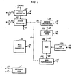
- FIG. 1 there is shown an overall view of a memory system (referred to as a Programmable Access Memory, or PAM) having a random access memory (RAM) 200, that may contain either static or dynamic cells and associated decoders, an access register array 100 through which data and addresses pass, a data path controller 150 for controlling the transfer of data between register 100, RAM 200 and associated circuitry including address calculation unit 300, address range unit 400 and data manipulation unit 500.
- PAM Programmable Access Memory
- a 16-bit data/address bus 10 accesses a set of access registers 100 to be described later; a 4-bit bus 20 is used to specify one or more of 16 access registers within unit 100; and a set of external control lines 30 is used to receive and acknowledge external control signals.
- Bus 20 enters access controller 120, which is a simple, self-timed controller that responds to external control signals and handles reading and writing to and from access registers 100 and the outside world.
- Control signals for enable, acknowledge, read, write and other standard functions enter bus 30 and cause controller 120 to latch input data: release output data; or pass a control signal on to other units.
- Data path controller 150 which, as will be described later, is a simplified finite state machine that has less complexity than a standard central processing unit.
- the operating mode of the system is determined and changed from time to time by transfer of the contents of a MODE register within access register unit 100 into controller 150.
- the contents of the register specify, among other things, the starting point of a subroutine in microcode memory within the controller unit.
- the control of the data path and the transfer of the MODE register contents and other information to and from the different units along the several buses is accomplished under control of unit 150 by means of a set of control lines that are generically indicated by the numeral 50, some portions of which control lines enter all the logical units.
- Data, addresses, and some control signals pass along bus 40 into address calculation module 300 and then to the other units.
- a single bus could be used, but at the cost of data throughput.
- a standard memory cell array unit, 200 including address decoders and controlled by standard RAM controller 220 (controller 220 is a standard unit well-known to those skilled in the art such as the one disclosed in Foss & Harland "Peripheral Circuits for One Transistor Cell MOS RAMs") is the basic unit that is effectively customized by the other units to simulate a number of specialized memory units.
- Address calculation unit 300 includes a simplified ALU having addition, subtraction and comparison functions to calculate an address and is used in various modes of the invention such as the FIFO, LIFO and indirect addressing modes.
- Address range unit 400 is used to check if the address on bus 42, whether calculated by unit 300, or coming from an address access register within unit 100, lies within a specified boundary range. This unit may conveniently be used to prevent reading or writing to a memory address outside that specified range.
- One use is to separate data from instructions within RAM 200 and to generate an error signal if the external central processing unit of the overall system has accidently attempted to write into an instruction storage cell. Another function is to do real time array bounds checking.
- the last unit, data manipulation unit 500 is used, as will be described below, to perform certain selected processing functions on the data within RAM 200.
- the invention can be used in an automatic search mode in which RAM 200 is searched until a particular pattern of data is found.
- the operating mode has previously been specified by sending a 4-bit address along bus 20, in response to which a mode register within unit 100 has been connected to bus 10.
- a 16-bit data address is placed on bus 10 by the system CPU and is loaded into the mode register. This process is controlled by access controller 120.
- mode addresses may be stored in unit 100. Control lines contained within control network 50 then stimulate the data path controller 150 to access the contents of the mode register, which cause the microcode within unit 150 to branch to a subroutine that initiates the sequence that follows.
- the standard read function is initiated by a system CPU or other device sending the 4-bit address of the memory address register (MAR) within unit 100 to controller 120 and also by placing the 16-bit address of the data to be read on bus 10.
- Unit 100 under control of controller 120, opens a path between bus 10 and the memory address register and writes the address into that register.
- data path controller 150 transmits the address to Address Calculation Unit 300 that, in this case merely passes it through to Address Range Unit 400 that checks that the address lies within an allowed range.
- Unit 400 then passes the address to RAM unit 200 which, in turn, handles the standard decoding function to access that particular cell memory address.
- the contents of the cells specified by that address are placed on bus 46; transmitted to Data Manipulation Unit 500; and then written into the memory data register (MDR) within unit 100.
- Access controller 120 then sends a control signal along bus 30 to the CPU indicating that the data is available in the address register and, in response to a read signal from the CPU, places the contents of the memory data register on bus 10.
- Two of the registers within access register unit 100 contain START and STOP registers defining an area within the address space of RAM 200. No memory accesses are allowed to addresses outside these boundaries. This feature may be used for automatic checking that the programmer is not attempting to read or write data that is outside the range of a memory array.
- Simple logical comparisons within Address Calculation Unit 300 provide standard tests that prevent data from being written into a full buffer or data being read out from an empty buffer. Appropriate error flags are set within the status register within unit 100.
- the FIFO mode is an example of a hardware assisted data abstraction, which is a hardware device or system that implements a data process in a manner such that the hardware configuration is invisible to the user.
- this feature will permit simple fast communications between two devices sharing the external system bus, such as direct memory access from an I/O device to the RAM without going through a system CPU.
- Registers within unit 100 are used as the registers required to implement a stack; namely a stack pointer, a starting address and an offset register.
- the stack may be implemented by doing the standard PUSH and POP functions, using Address Calculation Unit 300 to automatically increment and decrement the stack pointer as required.
- a stack offset operation may be used to store data in the memory data register in the RAM address indicated by the base register plus the offset register. Similarly, data is read out of the RAM address corresponding to the base plus offset sum.
- modification of the data may be performed in accordance with a prescribed recipe.
- a pattern of bits may be stored in a register (function) within access register unit 100.
- Data from the RAM could be logically processed as by NAND function, OR function, etc. with either input data or with a stored pattern.
- the data could be subjected to more complex operations such as addition with a constant, a variable, or preceding data.
- An address range within RAM 200 is filled with a pattern and function specified after which a completion signal is transmitted by access controller 120.
- the pattern may be constant or may vary within the address range.
- Registers store the start and length of the source and the start of the destination. This is sometimes called 'bit blit' or block transfer.
- an area of RAM 200 is modified according to a prescribed function until a certain pattern is reached.
- data path by which term is meant the sets of buses 40, 42, 44 and 40, 46 and the logic modules located between the buses that provide separate paths for addresses (which are regarded for purposes of this application as another form of data) and referred to as address data and the data that is stored within the memory array (memory data). If the functions described above, were to be performed by a programmed single-chip computer, the address would pass from an input register to the CPU and then to the memory and each of the functions of units 300, 400 and 500 would require at least one transfer from memory to the CPU and back again.
- the "intelligence" is in the Data Path Controller, which does not handle data or addresses. All comparisons, additions or other logical operations are done in units that are located in the data path and external to the Data Path Controller.
- PAM address extension
- the PAM will automatically store data to, or get data from, the correct address and coordinate with the MDR.
- a data base is stored as an array of records.
- the base may be searched by looking for a certain pattern in one entry in the record, or it may be searched by operating a test on one or more entries within the record and retrieving the record or records that satisfy the test.
- the data base could be a personnel record and a searching tag could be the employee's identification number.
- the pattern find operating mode number 7 may be used, with the pattern being the ID number that is stored within one of the registers 100.
- the contents of RAM unit 200 are searched until that pattern is found and the record associated with that pattern is output to the host computer.
- the operation should run two or three times faster than if done by the microprocessor because once the procedure is set up, with the length of the record defined and the location within the record of the tag entry, the only operation of the host microprocessor is to pass to the PAM the ID number that is being searched for.
- the host microprocessor need not implement a bus access to bring in each record and then do a comparison, so that the saving of bus access time will result in a considerably faster operation.
- a particular advantageous feature of the invention is the reduction in total operation time that results from simple searching and testing within the PAM and thus without involving the external bus.
- An extension of the invention to larger data bases results in an additional advantage in that two or more PAMs may be operating simultaneously to search a large data base with the same test. Records that satisfy the test may be sent to the host CPM using standard interrupt procedures.
- a further advantage of the invention for relatively small data bases or small areas of memory is that the same RAM unit 200 can be used in two or more modes sequentially. That is, the RAM may be used as a FIFO and also as a stack, the mode of operation being changed as required by a simple writing into the special purpose mode register of the correct control code.
- a set of registers for unit 100 that will effect the preceding operations is given in Table I in which parentheses indicate different functions of a register in alternative modes. Those skilled in the art will readily be able to add additional registers to accomplish other specialized functions.
- the 12 registers in Table I may be supplemented by an additional four registers and still be addressed by the 4-bit bus 20. Those skilled in the art will readily be able to supplement the illustrative operating modes and register configurations to accomplish additional specialized functions.
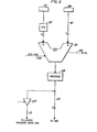
- FIG. 2 there is shown a simple embodiment of address calculation module 300.
- the heart of the module is ALU 310, a simple ALU having addition, subtraction and identity functions.
- ALU design is taught in Ward et al "Computation Structures", 1984.
- Two inputs, multiplexers 312 and 314, pass the contents of registers within unit 100 to the ALU 310.
- a temporary register 315 may be used for complicated address calculations.
- the function of the address calculation module is to calculate the current address for those operating modes that employ a pointer or other indirect addressing functions.
- a temporary register 320 latches the output of ALU 310 and the contents of register 320 are passed to address range module 400 along bus 42 or through gate 324 to access register 100, various registers of which will be updated as the result of the address calculation.
- the buses may be dedicated buses directly connecting one register or module with another.
- the Row Size input line to multiplexer 314 carries a constant input and is used to increment a row count register in the event that automatic refresh is desired. If RAM 200 is static, refresh is not necessary. This arrangement checks ALU overflow or underflow or (a special case) row number overflow or underflow. This tells when RAM address needs to be modified or could be invalid. Output signals are sent to controller 150 on lines 51 and 52 as part of control network 50.
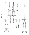
- an Address Range Module 400 The logical functions are performed on an address signal that may come either from the memory address register within unit 100 on bus 408 or from the output of address calculation module 300 on bus 406.
- One of these addresses is passed through multiplexer 410 and is input to three different 16-bit binary comparators 420, 430, or 440.
- Underflow and overflow signals on lines 424 and 434 respectively, are derived by comparison of the current address with a start address on line 422 or a stop (or offset) address on line 432. Both these addresses come from registers within access register unit 100.
- a third comparison is an empty/full indication for a FIFO buffer.
- a third multiplexer 460 takes one of the addresses on lines 406 (from the MAR) or 408 (from Address Calculation Module 300) and passes it to RAM 200.
- the point of having a separate multiplexer, gated by data path controller 150, is that either post-increment or decrement or pre-increment or decrement may be accomplished, at the option of the system designer.
- Figure 4 illustrates an embodiment of data manipulation module 500, similar in outline to the contents of Figure 2.
- a more complex ALU 510 having a full range of logical functions and also having arithmetic functions that include addition and subtraction accepts data along bus 46 from RAM 200 and also accepts either the contents of the memory data register or the pattern register from access register unit 100 through multiplexer 512.
- An input line 506 coming from the function register within unit 100 specifies which microcode subroutine within the ALU will be used to carry out the comparison or calculation.
- Temporary register 520 stores the result, which is returned to RAM 200 through bus 46 or to bus 40 through gate 524.
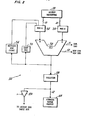
- Figure 5 illustrates a simplified diagram of data path controller 150.
- Control inputs from control line network 50 enter OR circuit 502 and pass into multiplexer 540 that also accepts a mode signal passing through synchronizer 530 that sychronizes the PAM controller with inputs from the host machine. This is necessary unless the PAM shares a clock with the host.
- the function of the mode value is to specify the starting point in the micro-RAM for the particular subroutine being executed.
- Micro-instruction register 520 is a conventional unit, well-known to those skilled in the art, such as illustrated in Ward & Halstead "Computation Structures., 1983, MIT describes the '6032 machine'. Another example is the LSI-11 from Digital Equipment Corporation.
- RAM 200 may be either static or dynamic, bipolar or MOS.
- Access registers 100 are meant to be understood as being general in nature. Any form of circuit that will hold data, including hard-wired voltage levels, EPROM circuits or pins maintained by an external circuit.
Abstract
Description
- The field of the invention is that of integrated circuit memories. In particular, the field is that of memories having processing capability incorporated within the memory unit.
- It is known to have overhead circuitry on random access memories to accomplish decoding functions, and, in the case of dynamic random access memories, to provide for automatic refreshing cycles that are invisible to the system programmer. Prior art memories typically have provision for direct access from the input terminals to the decoding logic for the memory cell array, in order to reduce the memory cycle time to a minimum.
- The invention relates to an intelligent memory that incorporates a controlling unit including an ALU on the same chip as the memory cell array.
- A feature of the invention is an architecture that provides a data path for passing addresses and data from a set of access registers through at least one processing unit to a memory array, the path being controlled by a finite-state machine that does not itself process data, and the data path having a first branch for addresses and a second branch for the data stored in the cells.
- Another feature of the invention is the use of indirect access in which all references to and from the cell array must be made through a set of control registers.
- Another feature of the invention is the provision of an array of control registers that includes a data register for storing the memory data to be written into or read out from the memory and an address register carrying the address associated with the currently available data.
- Yet another feature of the invention is the use of an address calculation unit to provide automatic indexing of the address.
- Yet another feature of the invention is the provision of registers to store the upper and lower boundaries of an address range, thereby making automatic bound checking for memory arrays possible.
- Yet another feature of the invention is a memory control sequence that provides for a FIFO memory unit constructed out of the random access memory.
- Yet another feature of the invention is the programmable conversion of the random access memory to a LIFO (stack) memory unit.
- Yet another feature of the invention is the provision for automatic searching within the memory array, thus providing a content-addressable memory.
- Yet another feature of the invention is the provision of an automatic sequence of modification of data stored-within the memory according to a prescribed rule.
- Yet another feature of the invention is the provision of additional address space greater than is available to a system CPU by means of a hardware assisted data abstraction involving indirect addressing.
- Brief Description of Drawings
- Figure 1 illustrates an overall block diagram of a memory contructed according to the invention.
- Figure 2 illustrates the Address Calculation Module from Figure 1.
- Figure 3 illustrates the Address Range Module from Figure 1.
- Figure 4 illustrates the Data Manipulation Module from Figure 1.
- Figure 5 illustrates the Data Path Controller from Figure 1.
- Referring now to Figure 1, there is shown an overall view of a memory system (referred to as a Programmable Access Memory, or PAM) having a random access memory (RAM) 200, that may contain either static or dynamic cells and associated decoders, an
access register array 100 through which data and addresses pass, adata path controller 150 for controlling the transfer of data betweenregister 100, RAM 200 and associated circuitry includingaddress calculation unit 300,address range unit 400 anddata manipulation unit 500. In most of the many modes of operation of the system, addresses and data will not simply travel into and out from RAM 200, as in a standard RAM, but will be checked or manipulated in one of the associated units. - It is convenient to consider first the three sets of input/output lines: a 16-bit data/address bus 10 accesses a set of
access registers 100 to be described later; a 4-bit bus 20 is used to specify one or more of 16 access registers withinunit 100; and a set of external control lines 30 is used to receive and acknowledge external control signals. Bus 20 entersaccess controller 120, which is a simple, self-timed controller that responds to external control signals and handles reading and writing to and fromaccess registers 100 and the outside world. Control signals for enable, acknowledge, read, write and other standard functions enter bus 30 and causecontroller 120 to latch input data: release output data; or pass a control signal on to other units. - Control of data paths within the memory system is done by
data path controller 150, which, as will be described later, is a simplified finite state machine that has less complexity than a standard central processing unit. The operating mode of the system is determined and changed from time to time by transfer of the contents of a MODE register withinaccess register unit 100 intocontroller 150. The contents of the register specify, among other things, the starting point of a subroutine in microcode memory within the controller unit. The control of the data path and the transfer of the MODE register contents and other information to and from the different units along the several buses is accomplished under control ofunit 150 by means of a set of control lines that are generically indicated by thenumeral 50, some portions of which control lines enter all the logical units. - Data, addresses, and some control signals pass along
bus 40 intoaddress calculation module 300 and then to the other units. A single bus could be used, but at the cost of data throughput. - A standard memory cell array unit, 200, including address decoders and controlled by standard RAM controller 220 (
controller 220 is a standard unit well-known to those skilled in the art such as the one disclosed in Foss & Harland "Peripheral Circuits for One Transistor Cell MOS RAMs") is the basic unit that is effectively customized by the other units to simulate a number of specialized memory units. - Three specialized units are used to effect some of the special functions of the memory system.
Address calculation unit 300 includes a simplified ALU having addition, subtraction and comparison functions to calculate an address and is used in various modes of the invention such as the FIFO, LIFO and indirect addressing modes.Address range unit 400 is used to check if the address onbus 42, whether calculated byunit 300, or coming from an address access register withinunit 100, lies within a specified boundary range. This unit may conveniently be used to prevent reading or writing to a memory address outside that specified range. One use is to separate data from instructions within RAM 200 and to generate an error signal if the external central processing unit of the overall system has accidently attempted to write into an instruction storage cell. Another function is to do real time array bounds checking. The last unit,data manipulation unit 500, is used, as will be described below, to perform certain selected processing functions on the data within RAM 200. As one example, the invention can be used in an automatic search mode in which RAM 200 is searched until a particular pattern of data is found. - Although the invention is intended to provide certain specialized functions requiring intelligence associated with the memory unit, it is convenient for purposes of explanation to start with an ordinary memory read cycle. In that case, the operating mode has previously been specified by sending a 4-bit address along bus 20, in response to which a mode register within
unit 100 has been connected to bus 10. Next, a 16-bit data address is placed on bus 10 by the system CPU and is loaded into the mode register. This process is controlled byaccess controller 120. Alternatively, mode addresses may be stored inunit 100. Control lines contained withincontrol network 50 then stimulate thedata path controller 150 to access the contents of the mode register, which cause the microcode withinunit 150 to branch to a subroutine that initiates the sequence that follows. - The standard read function is initiated by a system CPU or other device sending the 4-bit address of the memory address register (MAR) within
unit 100 tocontroller 120 and also by placing the 16-bit address of the data to be read on bus 10.Unit 100, under control ofcontroller 120, opens a path between bus 10 and the memory address register and writes the address into that register. Next,data path controller 150 transmits the address toAddress Calculation Unit 300 that, in this case merely passes it through toAddress Range Unit 400 that checks that the address lies within an allowed range.Unit 400 then passes the address to RAM unit 200 which, in turn, handles the standard decoding function to access that particular cell memory address. The contents of the cells specified by that address are placed onbus 46; transmitted toData Manipulation Unit 500; and then written into the memory data register (MDR) withinunit 100.Access controller 120 then sends a control signal along bus 30 to the CPU indicating that the data is available in the address register and, in response to a read signal from the CPU, places the contents of the memory data register on bus 10. - It will be evident to those skilled in the art that this sequence of steps is considerably more lengthy than the standard memory read sequence in a non-intelligent memory. In particular, there has been the extra step of sending the 4-bit address of the MAR to access
controller 120, in addition to the 16-bit memory address on bus 10. It is expected that this memory unit will not often be used in the standard read and write modes, though it may be convenient for system design to use the memory in this way from time to time. Most often, the total time for an operation to be accomplished will be substantially reduced by permitting the memory to do some bookkeeping and controlling within itself, without access along the system bus to the CPU. These specialized memory functions will next be described. - Two of the registers within
access register unit 100 contain START and STOP registers defining an area within the address space of RAM 200. No memory accesses are allowed to addresses outside these boundaries. This feature may be used for automatic checking that the programmer is not attempting to read or write data that is outside the range of a memory array. - Buffer):
- A set of registers START and STOP define the boundaries of an area within the address space of RAM 200 that is used for a FIFO (First In First Out) buffer that is implemented as a circular buffer. Additional registers IN PTR and OUT PTR point to the next write and read addresses, respectively. Additional registers IN INCR and OUT INCR define autoincrement amounts for writes and reads. This last feature is useful in data base applications where a record will consist of several words. Data is written into the data register in
unit 100 and automatically transferred to the next available space within the buffer, indicated by the IN PTR register. - Simple logical comparisons within
Address Calculation Unit 300 provide standard tests that prevent data from being written into a full buffer or data being read out from an empty buffer. Appropriate error flags are set within the status register withinunit 100. - The FIFO mode is an example of a hardware assisted data abstraction, which is a hardware device or system that implements a data process in a manner such that the hardware configuration is invisible to the user.
- Note that if the bus used in the overall system permits automatic read operations, which is standard in system operation, this feature will permit simple fast communications between two devices sharing the external system bus, such as direct memory access from an I/O device to the RAM without going through a system CPU.
- Registers within
unit 100 are used as the registers required to implement a stack; namely a stack pointer, a starting address and an offset register. The stack may be implemented by doing the standard PUSH and POP functions, usingAddress Calculation Unit 300 to automatically increment and decrement the stack pointer as required. - A stack offset operation may be used to store data in the memory data register in the RAM address indicated by the base register plus the offset register. Similarly, data is read out of the RAM address corresponding to the base plus offset sum.
- On any memory accesses, either before or after the read operation, modification of the data may be performed in accordance with a prescribed recipe. As one example, a pattern of bits may be stored in a register (function) within
access register unit 100. Data from the RAM could be logically processed as by NAND function, OR function, etc. with either input data or with a stored pattern. Also, the data could be subjected to more complex operations such as addition with a constant, a variable, or preceding data. - This is a special case of the preceding function access. An address range within RAM 200 is filled with a pattern and function specified after which a completion signal is transmitted by
access controller 120. The pattern may be constant or may vary within the address range. - Copy the contents of one address range within RAM 200 to another address range within RAM 200. Registers store the start and length of the source and the start of the destination. This is sometimes called 'bit blit' or block transfer.
- Locate the occurrence of a 16-bit pattern in some memory address range. This uses the same registers and logic as the write operation of the functional access,
mode number 4. This operating mode is useful in data base manipulation. - In this mode, an area of RAM 200 is modified according to a prescribed function until a certain pattern is reached.
- An important feature of the architecture of the PAM is the "data path", by which term is meant the sets of
buses units - Application of the Invention:
- The following examples illustrate some of the system configurations and uses that may be employed using alternative embodiments of the invention. 1. Additional address space. An embodiment of the invention may be used as a memory extension where the host memory does not have enough address space to
- accommodate the needed area. In this case, the PAM mode is put into the standard access mode. The memory address register receives a 16-bit number that is an address within RAM 200. The memory data register receives the contents of that address. This is an ordinary read operation from the point of view of a PAM, but, to the host computer the only memory addresses taken up by the PAM are the 16 locations that are required by 4-bit bus 20. The 4-bits of bus 20 corresponds to the 16 access registers within
unit 100. Thus, one or more PAMs may be attached to a host computer, each PAM having an address range of 64K but taking up only 16 words of the host physical memory. This is called 'Virtual Memory' or 'Indirect Memory'. - This use of the PAM as an address extension could be used in a hardware assisted data abstraction, which is a term to refer to any software data structure which is enhanced by special purpose hardware.
- To use the PAM as a FIFO, the system user would:
- 1) Load the FIFO mode number into the mode register.
- 2) Set up the START and STOP registers with the limits of the circular buffer that are to be used.
- 3) Initialize the IN PTR and OUT PTR to the same number (ideally 0). This makes the buffer be, initially, empty.
- 4) Begin data transfer.
- a. A READ is done by:
- i. Check the status register to be sure the buffer is not empty.
- ii. Do a READ from the MDR.
- b. A WRITE is done by:
- i. Check the status register to be sure the buffer is not full.
- ii. Do a WRITE to the MDR.
- The PAM will automatically store data to, or get data from, the correct address and coordinate with the MDR.
- A data base is stored as an array of records. The base may be searched by looking for a certain pattern in one entry in the record, or it may be searched by operating a test on one or more entries within the record and retrieving the record or records that satisfy the test.
- As a first example, the data base could be a personnel record and a searching tag could be the employee's identification number. In that case, the pattern find operating mode number 7 may be used, with the pattern being the ID number that is stored within one of the
registers 100. The contents of RAM unit 200 are searched until that pattern is found and the record associated with that pattern is output to the host computer. Note that since the search is being done by the PAM itself, the operation should run two or three times faster than if done by the microprocessor because once the procedure is set up, with the length of the record defined and the location within the record of the tag entry, the only operation of the host microprocessor is to pass to the PAM the ID number that is being searched for. The host microprocessor need not implement a bus access to bring in each record and then do a comparison, so that the saving of bus access time will result in a considerably faster operation. - Those skilled in the art will readily be able to implement many different systems employing this invention. A particular advantageous feature of the invention is the reduction in total operation time that results from simple searching and testing within the PAM and thus without involving the external bus.
- An extension of the invention to larger data bases results in an additional advantage in that two or more PAMs may be operating simultaneously to search a large data base with the same test. Records that satisfy the test may be sent to the host CPM using standard interrupt procedures.
- A further advantage of the invention for relatively small data bases or small areas of memory is that the same RAM unit 200 can be used in two or more modes sequentially. That is, the RAM may be used as a FIFO and also as a stack, the mode of operation being changed as required by a simple writing into the special purpose mode register of the correct control code.
- A set of registers for
unit 100 that will effect the preceding operations is given in Table I in which parentheses indicate different functions of a register in alternative modes. Those skilled in the art will readily be able to add additional registers to accomplish other specialized functions. The 12 registers in Table I may be supplemented by an additional four registers and still be addressed by the 4-bit bus 20. Those skilled in the art will readily be able to supplement the illustrative operating modes and register configurations to accomplish additional specialized functions. - Referring now to Figure 2, there is shown a simple embodiment of
address calculation module 300. The heart of the module isALU 310, a simple ALU having addition, subtraction and identity functions. Those skilled in the art will readily be able to devise many ALUs to perform these functions. ALU design is taught in Ward et al "Computation Structures", 1984. Two inputs,multiplexers unit 100 to theALU 310. Atemporary register 315 may be used for complicated address calculations. The function of the address calculation module, as noted above, is to calculate the current address for those operating modes that employ a pointer or other indirect addressing functions. Atemporary register 320 latches the output ofALU 310 and the contents ofregister 320 are passed to addressrange module 400 alongbus 42 or throughgate 324 to accessregister 100, various registers of which will be updated as the result of the address calculation. The buses may be dedicated buses directly connecting one register or module with another. The Row Size input line to multiplexer 314 carries a constant input and is used to increment a row count register in the event that automatic refresh is desired. If RAM 200 is static, refresh is not necessary. This arrangement checks ALU overflow or underflow or (a special case) row number overflow or underflow. This tells when RAM address needs to be modified or could be invalid. Output signals are sent tocontroller 150 onlines 51 and 52 as part ofcontrol network 50. - Referring now to Figure 3, there is shown an embodiment of an
Address Range Module 400. The logical functions are performed on an address signal that may come either from the memory address register withinunit 100 onbus 408 or from the output ofaddress calculation module 300 onbus 406. One of these addresses is passed throughmultiplexer 410 and is input to three different 16-bitbinary comparators lines line 422 or a stop (or offset) address online 432. Both these addresses come from registers withinaccess register unit 100. A third comparison is an empty/full indication for a FIFO buffer. This is produced by comparing the current address with either the IN PTR or OUT PTR, one of which is selected bymultiplexer 450 for comparison. Athird multiplexer 460 takes one of the addresses on lines 406 (from the MAR) or 408 (from Address Calculation Module 300) and passes it to RAM 200. The point of having a separate multiplexer, gated bydata path controller 150, is that either post-increment or decrement or pre-increment or decrement may be accomplished, at the option of the system designer. - Figure 4 illustrates an embodiment of
data manipulation module 500, similar in outline to the contents of Figure 2. A morecomplex ALU 510 having a full range of logical functions and also having arithmetic functions that include addition and subtraction accepts data alongbus 46 from RAM 200 and also accepts either the contents of the memory data register or the pattern register fromaccess register unit 100 throughmultiplexer 512. An input line 506 coming from the function register withinunit 100 specifies which microcode subroutine within the ALU will be used to carry out the comparison or calculation.Temporary register 520 stores the result, which is returned to RAM 200 throughbus 46 or tobus 40 throughgate 524. - Figure 5 illustrates a simplified diagram of
data path controller 150. Control inputs fromcontrol line network 50 enter OR circuit 502 and pass intomultiplexer 540 that also accepts a mode signal passing throughsynchronizer 530 that sychronizes the PAM controller with inputs from the host machine. This is necessary unless the PAM shares a clock with the host. The function of the mode value is to specify the starting point in the micro-RAM for the particular subroutine being executed.Micro-instruction register 520 is a conventional unit, well-known to those skilled in the art, such as illustrated in Ward & Halstead "Computation Structures., 1983, MIT describes the '6032 machine'. Another example is the LSI-11 from Digital Equipment Corporation. - Those skilled in the art will readily be able to configure modified embodiments of the invention in which different microcode within the finite state machine of Figure 5 modifies the general-purpose RAM to perform some particular application.
- The figures have been drawn in order to provide the greatest clarity and are schematic in nature. For example, and without limitation, two or more controllers may be physically the same, except for the microcode that controls the operations. Similarly, the actual wiring path between units may be a common bus or a network of direct lines. RAM 200 may be either static or dynamic, bipolar or MOS.
- Access registers 100 are meant to be understood as being general in nature. Any form of circuit that will hold data, including hard-wired voltage levels, EPROM circuits or pins maintained by an external circuit.

Claims (25)
Applications Claiming Priority (2)
| Application Number | Priority Date | Filing Date | Title |
|---|---|---|---|
| US06/781,584 US4835733A (en) | 1985-09-30 | 1985-09-30 | Programmable access memory |
| US781584 | 1985-09-30 |
Publications (3)
| Publication Number | Publication Date |
|---|---|
| EP0218523A2 true EP0218523A2 (en) | 1987-04-15 |
| EP0218523A3 EP0218523A3 (en) | 1989-12-06 |
| EP0218523B1 EP0218523B1 (en) | 1996-06-19 |
Family
ID=25123245
Family Applications (1)
| Application Number | Title | Priority Date | Filing Date |
|---|---|---|---|
| EP86402115A Expired - Lifetime EP0218523B1 (en) | 1985-09-30 | 1986-09-26 | programmable access memory |
Country Status (6)
| Country | Link |
|---|---|
| US (1) | US4835733A (en) |
| EP (1) | EP0218523B1 (en) |
| JP (1) | JPH0814801B2 (en) |
| KR (1) | KR950007448B1 (en) |
| AT (1) | ATE139633T1 (en) |
| DE (1) | DE3650532T2 (en) |
Cited By (4)
| Publication number | Priority date | Publication date | Assignee | Title |
|---|---|---|---|---|
| EP0326053A2 (en) * | 1988-01-28 | 1989-08-02 | National Semiconductor Corporation | Programmable memory data protection scheme |
| WO1994015320A1 (en) * | 1992-12-21 | 1994-07-07 | Base 10 Systems, Inc. | Portable memory device and method of securing the integrity of stored data therein |
| GB2271449B (en) * | 1992-09-29 | 1996-09-04 | Ricoh Kk | Method of processing data representative of a colour image |
| US6266285B1 (en) | 1990-04-18 | 2001-07-24 | Rambus Inc. | Method of operating a memory device having write latency |
Families Citing this family (28)
| Publication number | Priority date | Publication date | Assignee | Title |
|---|---|---|---|---|
| JPH0642263B2 (en) * | 1984-11-26 | 1994-06-01 | 株式会社日立製作所 | Data processing device |
| US5056014A (en) * | 1985-02-04 | 1991-10-08 | Lockheed Sanders, Inc. | Network simulation system |
| US5040153A (en) * | 1987-10-23 | 1991-08-13 | Chips And Technologies, Incorporated | Addressing multiple types of memory devices |
| US5146221A (en) * | 1989-01-13 | 1992-09-08 | Stac, Inc. | Data compression apparatus and method |
| US5758148A (en) * | 1989-03-10 | 1998-05-26 | Board Of Regents, The University Of Texas System | System and method for searching a data base using a content-searchable memory |
| US4989180A (en) * | 1989-03-10 | 1991-01-29 | Board Of Regents, The University Of Texas System | Dynamic memory with logic-in-refresh |
| US5777608A (en) * | 1989-03-10 | 1998-07-07 | Board Of Regents, The University Of Texas System | Apparatus and method for in-parallel scan-line graphics rendering using content-searchable memories |
| US6751696B2 (en) | 1990-04-18 | 2004-06-15 | Rambus Inc. | Memory device having a programmable register |
| US6324120B2 (en) | 1990-04-18 | 2001-11-27 | Rambus Inc. | Memory device having a variable data output length |
| GB9019026D0 (en) * | 1990-08-31 | 1990-10-17 | Ncr Co | Work station including a direct memory access controller |
| US5280595A (en) * | 1990-10-05 | 1994-01-18 | Bull Hn Information Systems Inc. | State machine for executing commands within a minimum number of cycles by accomodating unforseen time dependency according to status signals received from different functional sections |
| US5210856A (en) * | 1991-08-07 | 1993-05-11 | Chips And Technologies, Inc. | Non-aligned DRAM state machine for page-mode DRAM control |
| US5305454A (en) * | 1991-08-12 | 1994-04-19 | International Business Machines Corporation | Notification of event handlers in broadcast or propagation mode by event management services in a computer system |
| US5237684A (en) * | 1991-08-12 | 1993-08-17 | International Business Machines Corporation | Customized and versatile event monitor within event management services of a computer system |
| US5355484A (en) * | 1991-08-12 | 1994-10-11 | International Business Machines Corporation | Dynamically established event monitors in event management services of a computer system |
| US5625821A (en) * | 1991-08-12 | 1997-04-29 | International Business Machines Corporation | Asynchronous or synchronous operation of event signaller by event management services in a computer system |
| DE69327504T2 (en) * | 1992-10-19 | 2000-08-10 | Koninkl Philips Electronics Nv | Data processor with operational units that share groups of register memories |
| AU673069B2 (en) * | 1993-03-23 | 1996-10-24 | David Siu Fu Chung | Intelligent memory architecture |
| JPH08507888A (en) * | 1993-03-23 | 1996-08-20 | シウ フ チャン,デイヴィッド | Intelligent memory architecture |
| US5406554A (en) * | 1993-10-05 | 1995-04-11 | Music Semiconductors, Corp. | Synchronous FIFO having an alterable buffer store |
| US5636369A (en) * | 1995-05-26 | 1997-06-03 | Datron/Transco, Inc. | Fast pattern-detection machine and method |
| US6148034A (en) * | 1996-12-05 | 2000-11-14 | Linden Technology Limited | Apparatus and method for determining video encoding motion compensation vectors |
| US5953738A (en) * | 1997-07-02 | 1999-09-14 | Silicon Aquarius, Inc | DRAM with integral SRAM and arithmetic-logic units |
| JP2000029778A (en) * | 1998-07-14 | 2000-01-28 | Hitachi Ltd | Memory cell |
| JP2002175689A (en) * | 2000-09-29 | 2002-06-21 | Mitsubishi Electric Corp | Semiconductor integrated circuit device |
| JP2002108691A (en) | 2000-09-29 | 2002-04-12 | Mitsubishi Electric Corp | Semiconductor memory and method for controlling the same device |
| US20040133762A1 (en) * | 2003-01-06 | 2004-07-08 | Rui-Fu Chao | Linear access window |
| EP2706420B1 (en) * | 2012-09-05 | 2015-03-18 | Siemens Aktiengesellschaft | Method for operating an automation device |
Citations (2)
| Publication number | Priority date | Publication date | Assignee | Title |
|---|---|---|---|---|
| US3601809A (en) | 1968-11-04 | 1971-08-24 | Univ Pennsylvania | Addressable list memory systems |
| US4521874A (en) | 1982-09-28 | 1985-06-04 | Trw Inc. | Random access memory device |
Family Cites Families (12)
| Publication number | Priority date | Publication date | Assignee | Title |
|---|---|---|---|---|
| GB1268283A (en) * | 1970-04-02 | 1972-03-29 | Ibm | Connect module |
| JPS5140772B2 (en) * | 1971-07-26 | 1976-11-05 | ||
| US3914747A (en) * | 1974-02-26 | 1975-10-21 | Periphonics Corp | Memory having non-fixed relationships between addresses and storage locations |
| DE2517565C3 (en) * | 1975-04-21 | 1978-10-26 | Siemens Ag, 1000 Berlin Und 8000 Muenchen | Circuit arrangement for a data processing system |
| US4037205A (en) * | 1975-05-19 | 1977-07-19 | Sperry Rand Corporation | Digital memory with data manipulation capabilities |
| JPS5326542A (en) * | 1976-08-24 | 1978-03-11 | Mitsubishi Electric Corp | Information retrieval unit |
| JPS58192154A (en) * | 1982-05-07 | 1983-11-09 | Casio Comput Co Ltd | Memory device having automatic data processing function |
| JPS58208999A (en) * | 1982-05-28 | 1983-12-05 | Nec Corp | Memory device |
| JPS58208981A (en) * | 1982-05-28 | 1983-12-05 | Nec Corp | Address control circuit |
| JPS5956276A (en) * | 1982-09-24 | 1984-03-31 | Hitachi Ltd | Semiconductor storage device |
| JPS5960658A (en) * | 1982-09-30 | 1984-04-06 | Fujitsu Ltd | Semiconductor storage device provided with logical function |
| US4663742A (en) * | 1984-10-30 | 1987-05-05 | International Business Machines Corporation | Directory memory system having simultaneous write, compare and bypass capabilites |
-
1985
- 1985-09-30 US US06/781,584 patent/US4835733A/en not_active Expired - Lifetime
-
1986
- 1986-09-26 AT AT86402115T patent/ATE139633T1/en not_active IP Right Cessation
- 1986-09-26 EP EP86402115A patent/EP0218523B1/en not_active Expired - Lifetime
- 1986-09-26 DE DE3650532T patent/DE3650532T2/en not_active Expired - Fee Related
- 1986-09-29 KR KR1019860008153A patent/KR950007448B1/en not_active IP Right Cessation
- 1986-09-30 JP JP61233117A patent/JPH0814801B2/en not_active Expired - Lifetime
Patent Citations (2)
| Publication number | Priority date | Publication date | Assignee | Title |
|---|---|---|---|---|
| US3601809A (en) | 1968-11-04 | 1971-08-24 | Univ Pennsylvania | Addressable list memory systems |
| US4521874A (en) | 1982-09-28 | 1985-06-04 | Trw Inc. | Random access memory device |
Non-Patent Citations (2)
| Title |
|---|
| IBM TECHNICAL DISCLOSURE BULLETIN, vol. 25, no. 5, October 1982 (1982-10-01) |
| IEEE TRANSACTIONS ON COMPUTERS, June 1971 (1971-06-01), pages 671 - 674 |
Cited By (11)
| Publication number | Priority date | Publication date | Assignee | Title |
|---|---|---|---|---|
| EP0326053A2 (en) * | 1988-01-28 | 1989-08-02 | National Semiconductor Corporation | Programmable memory data protection scheme |
| EP0326053A3 (en) * | 1988-01-28 | 1991-01-02 | National Semiconductor Corporation | Programmable memory data protection scheme |
| US6266285B1 (en) | 1990-04-18 | 2001-07-24 | Rambus Inc. | Method of operating a memory device having write latency |
| US6314051B1 (en) | 1990-04-18 | 2001-11-06 | Rambus Inc. | Memory device having write latency |
| US6415339B1 (en) | 1990-04-18 | 2002-07-02 | Rambus Inc. | Memory device having a plurality of programmable internal registers and a delay time register |
| US6570814B2 (en) | 1990-04-18 | 2003-05-27 | Rambus Inc. | Integrated circuit device which outputs data after a latency period transpires |
| US6584037B2 (en) | 1990-04-18 | 2003-06-24 | Rambus Inc | Memory device which samples data after an amount of time transpires |
| GB2271449B (en) * | 1992-09-29 | 1996-09-04 | Ricoh Kk | Method of processing data representative of a colour image |
| US5630106A (en) * | 1992-09-29 | 1997-05-13 | Ricoh Company, Ltd. | DRAM controller including bus-width selection and data inversion |
| WO1994015320A1 (en) * | 1992-12-21 | 1994-07-07 | Base 10 Systems, Inc. | Portable memory device and method of securing the integrity of stored data therein |
| US5493665A (en) * | 1992-12-21 | 1996-02-20 | Base 10 Systems, Inc. | Portable memory device and method of securing the integrity of stored data therein utilizing a starting address and a stored memory cycle number |
Also Published As
| Publication number | Publication date |
|---|---|
| JPS6298440A (en) | 1987-05-07 |
| US4835733A (en) | 1989-05-30 |
| EP0218523B1 (en) | 1996-06-19 |
| JPH0814801B2 (en) | 1996-02-14 |
| ATE139633T1 (en) | 1996-07-15 |
| EP0218523A3 (en) | 1989-12-06 |
| DE3650532T2 (en) | 1996-10-31 |
| KR950007448B1 (en) | 1995-07-11 |
| DE3650532D1 (en) | 1996-07-25 |
| KR870003507A (en) | 1987-04-17 |
Similar Documents
| Publication | Publication Date | Title |
|---|---|---|
| US4835733A (en) | Programmable access memory | |
| US5239642A (en) | Data processor with shared control and drive circuitry for both breakpoint and content addressable storage devices | |
| US5319763A (en) | Data processor with concurrent static and dynamic masking of operand information and method therefor | |
| US5341500A (en) | Data processor with combined static and dynamic masking of operand for breakpoint operation | |
| US4831520A (en) | Bus interface circuit for digital data processor | |
| EP0192202A2 (en) | Memory system including simplified high-speed data cache | |
| JPS6053896B2 (en) | Memory system of data processing equipment | |
| US4491908A (en) | Microprogrammed control of extended integer and commercial instruction processor instructions through use of a data type field in a central processor unit | |
| US4348720A (en) | Microcomputer arranged for direct memory access | |
| US3624616A (en) | Dynamic allocation of multidimensional array memory space | |
| EP0518479B1 (en) | Processing system and method including memory selection | |
| US4764896A (en) | Microprocessor assisted memory to memory move apparatus | |
| EP0026648A2 (en) | Digital data transfer apparatus | |
| US4028670A (en) | Fetch instruction for operand address calculation | |
| US4314332A (en) | Memory control system | |
| JPS6319058A (en) | Memory device | |
| US6721937B2 (en) | Method and system for automated processor register instantiation | |
| US4628450A (en) | Data processing system having a local memory which does not use a directory device with distributed resident programs and a method therefor | |
| US3942156A (en) | Indirect arithmetic control | |
| JP2619425B2 (en) | Sequence controller | |
| JPS6362778B2 (en) | ||
| US6237071B1 (en) | Multiaccess circuit including arbitration capabilities to effectively perform pipeline and suspend operations according to its priority | |
| JPS63241647A (en) | Microprocessor | |
| JPS61269752A (en) | Control device for processing image | |
| JPS59163695A (en) | Testing system |
Legal Events
| Date | Code | Title | Description |
|---|---|---|---|
| PUAI | Public reference made under article 153(3) epc to a published international application that has entered the european phase |
Free format text: ORIGINAL CODE: 0009012 |
|
| AK | Designated contracting states |
Kind code of ref document: A2 Designated state(s): AT DE FR GB IT NL |
|
| PUAL | Search report despatched |
Free format text: ORIGINAL CODE: 0009013 |
|
| AK | Designated contracting states |
Kind code of ref document: A3 Designated state(s): AT DE FR GB IT NL |
|
| RHK1 | Main classification (correction) |
Ipc: G06F 12/06 |
|
| RAP1 | Party data changed (applicant data changed or rights of an application transferred) |
Owner name: SGS-THOMSON MICROELECTRONICS, INC. (A DELAWARE COR |
|
| 17P | Request for examination filed |
Effective date: 19900129 |
|
| 17Q | First examination report despatched |
Effective date: 19930729 |
|
| REG | Reference to a national code |
Ref country code: GB Ref legal event code: 732E |
|
| RAP1 | Party data changed (applicant data changed or rights of an application transferred) |
Owner name: SGS-THOMSON MICROELECTRONICS, INC. |
|
| GRAH | Despatch of communication of intention to grant a patent |
Free format text: ORIGINAL CODE: EPIDOS IGRA |
|
| GRAH | Despatch of communication of intention to grant a patent |
Free format text: ORIGINAL CODE: EPIDOS IGRA |
|
| GRAA | (expected) grant |
Free format text: ORIGINAL CODE: 0009210 |
|
| AK | Designated contracting states |
Kind code of ref document: B1 Designated state(s): AT DE FR GB IT NL |
|
| PG25 | Lapsed in a contracting state [announced via postgrant information from national office to epo] |
Ref country code: NL Free format text: LAPSE BECAUSE OF FAILURE TO SUBMIT A TRANSLATION OF THE DESCRIPTION OR TO PAY THE FEE WITHIN THE PRESCRIBED TIME-LIMIT Effective date: 19960619 Ref country code: AT Effective date: 19960619 |
|
| REF | Corresponds to: |
Ref document number: 139633 Country of ref document: AT Date of ref document: 19960715 Kind code of ref document: T |
|
| REF | Corresponds to: |
Ref document number: 3650532 Country of ref document: DE Date of ref document: 19960725 |
|
| ITF | It: translation for a ep patent filed |
Owner name: PORTA CHECCACCI E BOTTI S.R.L. |
|
| ET | Fr: translation filed | ||
| NLV1 | Nl: lapsed or annulled due to failure to fulfill the requirements of art. 29p and 29m of the patents act | ||
| PLBE | No opposition filed within time limit |
Free format text: ORIGINAL CODE: 0009261 |
|
| STAA | Information on the status of an ep patent application or granted ep patent |
Free format text: STATUS: NO OPPOSITION FILED WITHIN TIME LIMIT |
|
| 26N | No opposition filed | ||
| PGFP | Annual fee paid to national office [announced via postgrant information from national office to epo] |
Ref country code: FR Payment date: 19970909 Year of fee payment: 12 |
|
| PGFP | Annual fee paid to national office [announced via postgrant information from national office to epo] |
Ref country code: GB Payment date: 19970917 Year of fee payment: 12 |
|
| PGFP | Annual fee paid to national office [announced via postgrant information from national office to epo] |
Ref country code: DE Payment date: 19971010 Year of fee payment: 12 |
|
| PG25 | Lapsed in a contracting state [announced via postgrant information from national office to epo] |
Ref country code: GB Free format text: LAPSE BECAUSE OF NON-PAYMENT OF DUE FEES Effective date: 19980926 |
|
| GBPC | Gb: european patent ceased through non-payment of renewal fee |
Effective date: 19980926 |
|
| PG25 | Lapsed in a contracting state [announced via postgrant information from national office to epo] |
Ref country code: FR Free format text: LAPSE BECAUSE OF NON-PAYMENT OF DUE FEES Effective date: 19990531 |
|
| PG25 | Lapsed in a contracting state [announced via postgrant information from national office to epo] |
Ref country code: DE Free format text: LAPSE BECAUSE OF NON-PAYMENT OF DUE FEES Effective date: 19990701 |
|
| REG | Reference to a national code |
Ref country code: FR Ref legal event code: ST |
|
| PG25 | Lapsed in a contracting state [announced via postgrant information from national office to epo] |
Ref country code: IT Free format text: LAPSE BECAUSE OF NON-PAYMENT OF DUE FEES;WARNING: LAPSES OF ITALIAN PATENTS WITH EFFECTIVE DATE BEFORE 2007 MAY HAVE OCCURRED AT ANY TIME BEFORE 2007. THE CORRECT EFFECTIVE DATE MAY BE DIFFERENT FROM THE ONE RECORDED. Effective date: 20050926 |