EP0219280A2 - Method and apparatus for forming and wrapping a coin roll. - Google Patents
Method and apparatus for forming and wrapping a coin roll. Download PDFInfo
- Publication number
- EP0219280A2 EP0219280A2 EP86307636A EP86307636A EP0219280A2 EP 0219280 A2 EP0219280 A2 EP 0219280A2 EP 86307636 A EP86307636 A EP 86307636A EP 86307636 A EP86307636 A EP 86307636A EP 0219280 A2 EP0219280 A2 EP 0219280A2
- Authority
- EP
- European Patent Office
- Prior art keywords
- coin
- wrapping
- stack
- coins
- roll
- Prior art date
- Legal status (The legal status is an assumption and is not a legal conclusion. Google has not performed a legal analysis and makes no representation as to the accuracy of the status listed.)
- Granted
Links
Images


Classifications
-
- B—PERFORMING OPERATIONS; TRANSPORTING
- B65—CONVEYING; PACKING; STORING; HANDLING THIN OR FILAMENTARY MATERIAL
- B65D—CONTAINERS FOR STORAGE OR TRANSPORT OF ARTICLES OR MATERIALS, e.g. BAGS, BARRELS, BOTTLES, BOXES, CANS, CARTONS, CRATES, DRUMS, JARS, TANKS, HOPPERS, FORWARDING CONTAINERS; ACCESSORIES, CLOSURES, OR FITTINGS THEREFOR; PACKAGING ELEMENTS; PACKAGES
- B65D65/00—Wrappers or flexible covers; Packaging materials of special type or form
- B65D65/02—Wrappers or flexible covers
- B65D65/14—Wrappers or flexible covers with areas coated with adhesive
-
- B—PERFORMING OPERATIONS; TRANSPORTING
- B65—CONVEYING; PACKING; STORING; HANDLING THIN OR FILAMENTARY MATERIAL
- B65D—CONTAINERS FOR STORAGE OR TRANSPORT OF ARTICLES OR MATERIALS, e.g. BAGS, BARRELS, BOTTLES, BOXES, CANS, CARTONS, CRATES, DRUMS, JARS, TANKS, HOPPERS, FORWARDING CONTAINERS; ACCESSORIES, CLOSURES, OR FITTINGS THEREFOR; PACKAGING ELEMENTS; PACKAGES
- B65D71/00—Bundles of articles held together by packaging elements for convenience of storage or transport, e.g. portable segregating carrier for plural receptacles such as beer cans or pop bottles; Bales of material
- B65D71/0085—Packaging elements adhered to the articles, e.g. a carton sheet
-
- B—PERFORMING OPERATIONS; TRANSPORTING
- B65—CONVEYING; PACKING; STORING; HANDLING THIN OR FILAMENTARY MATERIAL
- B65D—CONTAINERS FOR STORAGE OR TRANSPORT OF ARTICLES OR MATERIALS, e.g. BAGS, BARRELS, BOTTLES, BOXES, CANS, CARTONS, CRATES, DRUMS, JARS, TANKS, HOPPERS, FORWARDING CONTAINERS; ACCESSORIES, CLOSURES, OR FITTINGS THEREFOR; PACKAGING ELEMENTS; PACKAGES
- B65D85/00—Containers, packaging elements or packages, specially adapted for particular articles or materials
- B65D85/58—Containers, packaging elements or packages, specially adapted for particular articles or materials for ball bearings, washers, buttons or like spherical or disc-shaped articles
-
- G—PHYSICS
- G07—CHECKING-DEVICES
- G07D—HANDLING OF COINS OR VALUABLE PAPERS, e.g. TESTING, SORTING BY DENOMINATIONS, COUNTING, DISPENSING, CHANGING OR DEPOSITING
- G07D9/00—Counting coins; Handling of coins not provided for in the other groups of this subclass
- G07D9/06—Devices for stacking or otherwise arranging coins on a support, e.g. apertured plate for use in counting coins
- G07D9/065—Devices for wrapping coins
Definitions
- the present invention relates generally to wrapped coin rolls and methods of forming the same.
- Another important object is to provide an improved wrapped coin roll which does not require crimping of the wrapping material at the ends of the coin roll.
- Still another object of this invention is to provide an improved wrapped coin roll which can be easily opened.
- a wrapped roll of coins comprising a roll of coins having a length and a circumference; and a wrapper comprising (i) a flexible substrate having a substrate length and a substrate width, the substrate width being greater than the circumference of the roll, and the substrate length being at least as great as the length of the roll; along the length of the substrate an inside edge which contacts the length of the roll and, at the opposite end of the substrate, an outside edge; along the width of the substrate a pair of side edges, an inner surface which faces radially toward the roll; and an outer surface which faces radially away from the roll; and (ii) on the inner surface of the flexible substrate proximate the side edge, a coin-supporting amount of an effective clean-releasing pressure-sensitive adhesive, wherein the adhesive securely retains the coins within the wrapper and the coins can be selectively cleanly released from the wrapper without tearing the wrapper, whereby the wrapper can be reused.
- a method for selectively holding a roll of coins having a circumference, a length, two ends and two opposite circular sides comprising (a) arranging coins to form the roll of coins; (b) selecting a flexible substrate having a substrate length and a substrate width, the substrate width being greater than the circumference of the roll, and the substrate length being at least as great as the length of the roll; along the length of the substrate an inside edge which is suitable for contacting the length of the roll and, at the opposite end of the substrate, an outside edge; along the width of the substrate a pair of side edges; an inner surface suitable for contacting the roll of coins; and an outer surface opposite the inner surface, wherein on the inner surface proximate the side edges is a coin-supporting amount of an effective clean-releasing pressure-sensitive adhesive; (c) contacting the length of the roll with the inside edge of the flexible substrate such that the ends of the coin roll are in contact with the adhesive; (d) wrapping the roll in the flexible substrate, wherein the inner surface
- a coin wrapping mechanism for wrapping rolls of coins, said mechanism comprising coin stacking means for forming a coin stack containing a predetermined number of coins, means for supporting the coin stack for rotation about its axis, means for rotating the coin stack about its axis while pressing a wrapping material against the coin stack, said wrapping material having a coating of a pressure-sensitive, releasable adhesive on the side facing the coin stack so that the adhesive adheres to, and is wound around, the coin stack,and means for removing the coin stack from the rotating means after the desired length of wrapping material has been wound around the coins.
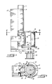
- Figs. 1, 2 and 3 illustrate a coin roll wrapping mechanism in three successive stages of operation.
- a coin stack 10 having a known length and circumference (with two ends and two opposite circular sides) is loaded from a buffer tube 11 into a wrapping chamber C formed by a housing 12.
- the buffer tube 11 is pivotally supported in the upper portion of the housing 12 by a pair of diametrically opposed pins 13 and 14 fitting into recesses in the outside wall of the tube 11, so that the lower end of the tube can be pivoted between (1) a "load buffer" position (illustrated in Figs.
- the coin stack 10 which contains a prescribed number of coins of a given denomination, may be formed by any of a variety of different coin counting and stacking mechanisms, such as the one described in Nakamura et al. US Patent No. 4,515,172. Such stacking mechanisms typically have a shutter which opens each time it is desired to load a new coin stack into the wrapping mechanism. When the shutter opens, the coin stack 10 drops into the buffer tube 11. Alternatively, the desired number of coins can be loaded into the buffer tube 11 by hand.
- a rotatable cam 16 with a smoothly rounded leading edge 17 engages the outside wall of the tube 11 near the lower end thereof and pushes the lower end of the tube to its retracted position (as shown in Fig. 1 and 2). The outer edge of the cam 16 then maintains the tube 11 in its retracted position throughout the wrapping of the coin stack in the wrapping chamber.
- a spring 19 pivots the tube to its advanced or "load buffer” position (illustrated in Fig. 3). The relationship of the rotational movement of the cam 16 and the wrapping mechanism will be apparent from the ensuing description.
- the stack of coins loaded into the wrapping chamber C rests on a disc 20 extending radially outwardly from the bottom of a wrapping roller 21 adjacent the wrapping chamber.
- Lateral support for the coin stack 10 is provided by a pair of idler rollers 21 a and 21 b recessed in the walls of the wrapping chamber C , a spring-loaded exit gate 22, and the wrapping roller 21.
- the coin stack 10 is free to rotate about its longitudinal axis while supported in this manner within the wrapping chamber.
- the cam 16 is mounted on the top of the wrapping roller 21, which extends slightly above the top of the coin stack 10.
- This sheet of wrapping material 30 forms a flexible substrate having a width W greater than the circumference of the roll and a length L at least as great as the length of the roll.
- One side of this wrapping material 30, namely the side facing the coin stack 10 is coated with a pressure-sensitive, releasable adhesive 31, such as No. 4351 film tape available from Can-Do Inc., Nashville, Tennessee.
- a pressure-sensitive, releasable adhesive 31 such as No. 4351 film tape available from Can-Do Inc., Arlington, Tennessee.
- Other suitable adhesives are those disclosed in US Patent No. 4,418,120 as having good tack and shear properties but low peel adhesion to stainless steel.
- the adhesive should adhere quickly to the outer surface of a stack of coins and have sufficient shear strength to securely retain the coins within the wrapper during handling, and yet had a peel adhesion low enough to be effectively clean-releasing, permitting and wrapping material to be readily peeled off the coil roll without leaving any substantial residue of adhesive on the coins and without tearing the wrapping material.
- the wrapper can be re-used.
- the adhesive coating 31 is preferably continuous along the full length and across the full width of the material 30.
- a resilient rubber or foamed-polymer pad 23 is bonded to the outer surface of the wrapping roller 21. It will be noted that the resilient pad 23 does not extend all the way around the circumference of the wrapping roller 21, thereby forming an "open" angle a within which a new sheet of wrapping material 30 can be inserted into the throat between the roller 21 and the coin stack 10 in each revolution of the roller. Then when the leading edge of the resilient pad 23 engages the new sheet of wrapping material, the pad 23 presses the leading edge 32 of the wrapping material 30 against the coin stack. Because of the adhesive coating on the side of the wrapping material 30 facing the coin stack, the wrapping material adheres to the coin stack.
- the circumferential length of the pad 23 is only slightly longer than the circumference of the coin stack, so that only one layer of the wrapping material is wound around the major portion of the stack with only the trailing edge 33 of the wrapping material overlapping and adhered to the first layer of wrapping material. It will be recognised, however, that the diameter of the roller 21 and/or the circumferential length of the pad 23 can be increased to wrap two or more layers of wrapping material around the stack of coins. If desired, the pad 23 can extend around the entire circumference of the roller 21, with the roller being retracted away from the coin stack during a portion of each revolution to allow a new sheet of wrapping material 30 to be fed into the wrapping mechanism.
- the height of the resilient pad 23 is slightly greater than the height of the coin stack 10 to ensure that the last coin at both ends of the stack is secured by the adhesive 31 adjacent the side edges 34 and 35 of the wrapping material. If desired, a small extra length of wrapping material can be folded over the ends of the coin stack, but there is no need for the crimping operation required by present coin wrapping machines, because the coins are retained within the wrapper by the adhesive coating on the wrapping material.
- a pair of ejector pins 40 and 41 project laterally from the wrapping roller 21 a short distance behind the trailing edge of the resilient pad 23. As these ejector pins 40 and 41 come into engagement with the wrapped coin roll, they push the coin roll against the spring-loaded exit gate 22, thereby pushing the gate open against its spring bias and ejecting the wrapped coin roll through the opened gate.
- a shoulder 42 and the support disc 20 also engages the wrapped coin roll and assists in ejecting the coin roll from the wrapping mechanism.
- the spring load on the gate returns the gate to its closed position.
- the roller 21 is fastened to a drive shaft 50 journaled in a support plates 51 cantilevered from the bottom of the housing 12.
- the drive shaft 50 in turn carries a drive pinion 52 which can be driven by any suitable drive means, such as a toothed belt driven by an electric motor. If desired, the drive shaft 50 could be driven directly by an electric motor.
- Fig. 7 illustrates a partially wrapped coin roll, with the adhesive-coated inner surface of the leading edge 32 of the wrapping material 30 contacting the coin stack 10 along the lengths of the coin stack and the wrapping material.
- the surface of the wrapping material 30 which faces radially toward the coin roll is referred to here as the “inner” surface, while the surface which faces radially away from the coin roll is referred to as the “outer” surface).
- the trailing edge 33 of the adhesive-coated inside surface of the wrapping material 30 overlaps the outside surface of the leading edge 32 and is adhered thereto by the adhesive 31.
- the adhesive coating along the side edges 34 and 35 of the wrapping material adheres to the coins at the ends of the roll to securely retain those coins in the roll; thus, the adhesive coating proximate the side edges 34 and 35 must contain a coin-supporting amount of the adhesive 31. Because the adhesive 31 is clean-releasing, the coins are selectively held in the wrapper and can be selectively cleanly released from the wrapper by removing the wrapper by merely peeling off the wrapper, whereby the roll of coins is cleanly released.
Landscapes
- Engineering & Computer Science (AREA)
- Mechanical Engineering (AREA)
- Physics & Mathematics (AREA)
- General Physics & Mathematics (AREA)
- Basic Packing Technique (AREA)
Abstract
Description
- The present invention relates generally to wrapped coin rolls and methods of forming the same.
- It is an object of the present invention to provide a wrapped coin roll which can be easily formed without the use of complex guiding mechanisms to control the wrapping material during the coin-wrapping operation.
- Another important object is to provide an improved wrapped coin roll which does not require crimping of the wrapping material at the ends of the coin roll.
- Still another object of this invention is to provide an improved wrapped coin roll which can be easily opened.
- According to the present invention, there is provided a wrapped roll of coins comprising a roll of coins having a length and a circumference; and a wrapper comprising (i) a flexible substrate having a substrate length and a substrate width, the substrate width being greater than the circumference of the roll, and the substrate length being at least as great as the length of the roll; along the length of the substrate an inside edge which contacts the length of the roll and, at the opposite end of the substrate, an outside edge; along the width of the substrate a pair of side edges, an inner surface which faces radially toward the roll; and an outer surface which faces radially away from the roll; and (ii) on the inner surface of the flexible substrate proximate the side edge, a coin-supporting amount of an effective clean-releasing pressure-sensitive adhesive, wherein the adhesive securely retains the coins within the wrapper and the coins can be selectively cleanly released from the wrapper without tearing the wrapper, whereby the wrapper can be reused.
- According to a further aspect of the present invention there is provided a method for selectively holding a roll of coins having a circumference, a length, two ends and two opposite circular sides, comprising (a) arranging coins to form the roll of coins; (b) selecting a flexible substrate having a substrate length and a substrate width, the substrate width being greater than the circumference of the roll, and the substrate length being at least as great as the length of the roll; along the length of the substrate an inside edge which is suitable for contacting the length of the roll and, at the opposite end of the substrate, an outside edge; along the width of the substrate a pair of side edges; an inner surface suitable for contacting the roll of coins; and an outer surface opposite the inner surface, wherein on the inner surface proximate the side edges is a coin-supporting amount of an effective clean-releasing pressure-sensitive adhesive; (c) contacting the length of the roll with the inside edge of the flexible substrate such that the ends of the coin roll are in contact with the adhesive; (d) wrapping the roll in the flexible substrate, wherein the inner surface of the flexible substrate is in operable contact with the coins around the circumference of the roll of coins and wherein the ends of coin roll are securely retained by the adhesive; and (e) removing the flexible substrate to unwrap the roll, wherein the roll of coins is cleanly released and wherein the flexible substrate can be reused.
- According to yet another aspect of the present invention there is provided a coin wrapping mechanism for wrapping rolls of coins, said mechanism comprising
coin stacking means for forming a coin stack containing a predetermined number of coins,
means for supporting the coin stack for rotation about its axis,
means for rotating the coin stack about its axis while pressing a wrapping material against the coin stack, said wrapping material having a coating of a pressure-sensitive, releasable adhesive on the side facing the coin stack so that the adhesive adheres to, and is wound around, the coin stack,and
means for removing the coin stack from the rotating means after the desired length of wrapping material has been wound around the coins. - An embodiment of the present invention will now be described, by way of example, with reference to the accompanying drawings, in which:-
- Fig. 1 is a perspective view of a coin wrapping mechanism, in a first stage of its operation, for forming a coin roll embodying the present invention;
- Fig. 2 is a perspective view of the coin wrapping mechanism of Fig. 1 in a second stage of its operation;
- Fig. 3 is a perspective view of the coin wrapping mechanism of Fig. 1 in a third stage of its operation;
- Fig. 4 is a top plan view of the coin wrapping mechanism of Fig. 1;
- Fig. 5 is a side elevation taken generally along line 5-5 in Fig. 4;
- Fig. 6 is a section taken generally along line 6-6 in Fig. 5;
- Fig. 7 is a perspective view of a partially wrapped coin roll; and
- Fig. 8 is a perspective view of a completely wrapped coin roll formed by the mechanism of Fig. 1.
- In the drawings, Figs. 1, 2 and 3 illustrate a coin roll wrapping mechanism in three successive stages of operation. Referring first to Fig. 1, a
coin stack 10 having a known length and circumference (with two ends and two opposite circular sides) is loaded from a buffer tube 11 into a wrapping chamber C formed by ahousing 12. The buffer tube 11 is pivotally supported in the upper portion of thehousing 12 by a pair of diametrically opposedpins shoulder 15 formed by thehousing 12 directly above and adjacent to the wrapping chamber C, and (2) a "load wrapper" position (illustrated in Fig. 3) where the bottom of the tube 11 opens directly into the wrapping chamber C. In the "load buffer" position, the tube 11 receives a pre-counted stack of coins in readiness for the next wrapping operation. In the "load wrapper" position, the stack of coins accumulated in the buffer tube 11 is dropped into the wrapping chamber C, ready to be wrapped. - The
coin stack 10, which contains a prescribed number of coins of a given denomination, may be formed by any of a variety of different coin counting and stacking mechanisms, such as the one described in Nakamura et al. US Patent No. 4,515,172. Such stacking mechanisms typically have a shutter which opens each time it is desired to load a new coin stack into the wrapping mechanism. When the shutter opens, the coin stack 10 drops into the buffer tube 11. Alternatively, the desired number of coins can be loaded into the buffer tube 11 by hand. - In order to pivot the buffer tube 11 to its retracted or "load buffer" position after the coins in the buffer tube have been dropped into the wrapping chamber C, a
rotatable cam 16 with a smoothly rounded leadingedge 17 engages the outside wall of the tube 11 near the lower end thereof and pushes the lower end of the tube to its retracted position (as shown in Fig. 1 and 2). The outer edge of thecam 16 then maintains the tube 11 in its retracted position throughout the wrapping of the coin stack in the wrapping chamber. When thetrailing edge 18 of thecam 16 clears the tube 11, aspring 19 pivots the tube to its advanced or "load buffer" position (illustrated in Fig. 3). The relationship of the rotational movement of thecam 16 and the wrapping mechanism will be apparent from the ensuing description. - The stack of coins loaded into the wrapping chamber C rests on a
disc 20 extending radially outwardly from the bottom of awrapping roller 21 adjacent the wrapping chamber. Lateral support for thecoin stack 10 is provided by a pair of idler rollers 21a and 21b recessed in the walls of the wrapping chamber C, a spring-loadedexit gate 22, and thewrapping roller 21. Thecoin stack 10 is free to rotate about its longitudinal axis while supported in this manner within the wrapping chamber. Thecam 16 is mounted on the top of thewrapping roller 21, which extends slightly above the top of thecoin stack 10. - A sheet of wrapping
material 30, such as a plastic film or paper, is fed between thecoin stack 10 and thewrapping roller 21, either manually or by an automatic sheet feeder. This sheet of wrappingmaterial 30 forms a flexible substrate having a width W greater than the circumference of the roll and a length L at least as great as the length of the roll. One side of this wrappingmaterial 30, namely the side facing thecoin stack 10, is coated with a pressure-sensitive, releasable adhesive 31, such as No. 4351 film tape available from Can-Do Inc., Nashville, Tennessee. Other suitable adhesives are those disclosed in US Patent No. 4,418,120 as having good tack and shear properties but low peel adhesion to stainless steel. That is, the adhesive should adhere quickly to the outer surface of a stack of coins and have sufficient shear strength to securely retain the coins within the wrapper during handling, and yet had a peel adhesion low enough to be effectively clean-releasing, permitting and wrapping material to be readily peeled off the coil roll without leaving any substantial residue of adhesive on the coins and without tearing the wrapping material. If desired, the wrapper can be re-used. Theadhesive coating 31 is preferably continuous along the full length and across the full width of thematerial 30. - In order to press the wrapping
material 30 against thecoin stack 10, while simultaneously rotating the coin stack, a resilient rubber or foamed-polymer pad 23 is bonded to the outer surface of thewrapping roller 21. It will be noted that theresilient pad 23 does not extend all the way around the circumference of thewrapping roller 21, thereby forming an "open" angle a within which a new sheet of wrappingmaterial 30 can be inserted into the throat between theroller 21 and thecoin stack 10 in each revolution of the roller. Then when the leading edge of theresilient pad 23 engages the new sheet of wrapping material, thepad 23 presses the leadingedge 32 of the wrappingmaterial 30 against the coin stack. Because of the adhesive coating on the side of the wrappingmaterial 30 facing the coin stack, the wrapping material adheres to the coin stack. - Continued rotation of the
roller 21 and thepad 23 causes the coin stack to rotate because theresilient pad 23 continues to press against the coin stack, through the wrappingmaterial 30. As the coin stack is rotated, the sheet of wrappingmaterial 30 follows the rotating surface of the stack, both because the wrapping material is adhered to the surface of the stack and because the wrapping material is drawn into the nip between theroller 21 and thecoin stack 10, and continues to be pressed against the coin stack, by theresilient pad 23. Thus, the wrapping material is wound tightly around thecoin stack 10 as the stack is driven by thepad 23. - In the illustrative embodiment, the circumferential length of the
pad 23 is only slightly longer than the circumference of the coin stack, so that only one layer of the wrapping material is wound around the major portion of the stack with only thetrailing edge 33 of the wrapping material overlapping and adhered to the first layer of wrapping material. It will be recognised, however, that the diameter of theroller 21 and/or the circumferential length of thepad 23 can be increased to wrap two or more layers of wrapping material around the stack of coins. If desired, thepad 23 can extend around the entire circumference of theroller 21, with the roller being retracted away from the coin stack during a portion of each revolution to allow a new sheet of wrappingmaterial 30 to be fed into the wrapping mechanism. - The height of the
resilient pad 23 is slightly greater than the height of thecoin stack 10 to ensure that the last coin at both ends of the stack is secured by theadhesive 31 adjacent theside edges - As the trailing edge of the
resilient pad 23 clears thecoin stack 10, rotation of the coin stack ceases. At this point, the sheet of wrappingmaterial 30 has been wound around the entire circumference of thecoin stack 10 and releasably bonded thereto. To eject the wrapped coin roll from the wrapping mechanism, a pair ofejector pins resilient pad 23. As theseejector pins exit gate 22, thereby pushing the gate open against its spring bias and ejecting the wrapped coin roll through the opened gate. At the same time theejector pins shoulder 42 and thesupport disc 20 also engages the wrapped coin roll and assists in ejecting the coin roll from the wrapping mechanism. After the coin roll has cleared thegate 22, the spring load on the gate returns the gate to its closed position. - For the purpose of driving the
wrapping roller 21 and thecam 16 and supportdisc 20 attached to the upper and lower ends thereof, theroller 21 is fastened to adrive shaft 50 journaled in asupport plates 51 cantilevered from the bottom of thehousing 12. Thedrive shaft 50 in turn carries adrive pinion 52 which can be driven by any suitable drive means, such as a toothed belt driven by an electric motor. If desired, thedrive shaft 50 could be driven directly by an electric motor. - Fig. 7 illustrates a partially wrapped coin roll, with the adhesive-coated inner surface of the leading
edge 32 of the wrappingmaterial 30 contacting thecoin stack 10 along the lengths of the coin stack and the wrapping material. (The surface of the wrappingmaterial 30 which faces radially toward the coin roll is referred to here as the "inner" surface, while the surface which faces radially away from the coin roll is referred to as the "outer" surface). In the final wrapped coin roll, shown in Fig. 8, the trailingedge 33 of the adhesive-coated inside surface of the wrappingmaterial 30 overlaps the outside surface of the leadingedge 32 and is adhered thereto by the adhesive 31. The adhesive coating along the side edges 34 and 35 of the wrapping material adheres to the coins at the ends of the roll to securely retain those coins in the roll; thus, the adhesive coating proximate the side edges 34 and 35 must contain a coin-supporting amount of the adhesive 31. Because the adhesive 31 is clean-releasing, the coins are selectively held in the wrapper and can be selectively cleanly released from the wrapper by removing the wrapper by merely peeling off the wrapper, whereby the roll of coins is cleanly released.
Claims (17)
(i) a flexible substrate (30) having: a substrate length and a substrate width, the substrate width being greater than the circumference of the roll (10), and the substrate length being at least as great as the length of the roll; along the length of the substrate (30) an inside edge which contacts the length of the roll and, at the opposite end of the substrate, an outside edge; along the width of the substrate a pair of side edges; an inner surface which faces radially toward the roll; and an outer surface which faces radially away from the roll; and
(ii) on the inner surface of the flexible substrate proximate the side edges, a coin-supporting amount of an effective clean-releasing pressure-sensitive adhesive (31), wherein the adhesive securely retains the coins within the wrapper and the coins can be selectively cleanly released from the wrapper without tearing the wrapper, whereby the wrapper can be reused.
arranging a predetermined number of coins to form a coin stack (10),
contacting the coin stack (10) with a wrapping material (30) coated on the side facing the coin stack with a coin-supporting amount of an effective clean-releasing pressure-sensitive adhesive (31), the coin stack (10) being contacted with the adhesive-coated side of said wrapping material (30), said wrapping material (30) having a width greater than the circumference of said coin stack (10) and a length at least as great as the length of said coin stack (10),
rotating the coin stack (10) about its axis while pressing said wrapping material (30) against the coin stack (10) so that the adhesive (31) bonds the wrapping material (30) to the coin stack (10) and causes the wrapping material (30) to be wound around the coin stack (10) to form a coin roll, said adhesive being located to engage at least the endmost coins in said stack to securely retain said coin stack (10) within said wrapping material (30), and
subsequently removing said coins from said roll by removing said wrapping material (30) and the adhesive thereon from said coins.
coin stacking means (11,12) for forming a coin stack (10) containing a predetermined number of coins,
means (20) for supporting the coin stack for rotation about its axis,
means (21) for rotating the coin stack about its axis while pressing a wrapping material (30) against the coin stack (10), said wrapping material (30) having a coating of a pressure-sensitive, releasable adhesive (31) on the side facing the coin stack (10) so that the adhesive adheres to, and is wound around, the coin stack (10), and
means (40,42) for removing the coin stack (10) from the rotating means (23) after the desired length of wrapping material has been wound around the coins.
means (20) for supporting a coin stack (10), containing a predetermined number of coins, for rotation about its axis, said supporting means (20) allowing a selected length of a wrapping material (30) to be fed into a position adjacent one side of said coin stack (10), said wrapping material having a coating (31) of a pressure-sensitive, releasable adhesive on the side facing said coin stack (10),
means (23) for engaging an edge portion of said wrapping material (30) with said coin stack (10) so that said adhesive adheres to the coin stack, and
drive means (21) for rotating said coin stack (10) about its axis so that said wrapping material (30) is wound around the coins and releasably bonded thereto.
Applications Claiming Priority (4)
| Application Number | Priority Date | Filing Date | Title |
|---|---|---|---|
| US78534285A | 1985-10-07 | 1985-10-07 | |
| US785342 | 1985-10-07 | ||
| US785343 | 1985-10-07 | ||
| US06/785,343 US4718218A (en) | 1985-10-07 | 1985-10-07 | Coin wrapping mechanism |
Publications (3)
| Publication Number | Publication Date |
|---|---|
| EP0219280A2 true EP0219280A2 (en) | 1987-04-22 |
| EP0219280A3 EP0219280A3 (en) | 1989-03-01 |
| EP0219280B1 EP0219280B1 (en) | 1994-01-05 |
Family
ID=27120391
Family Applications (1)
| Application Number | Title | Priority Date | Filing Date |
|---|---|---|---|
| EP86307636A Expired - Lifetime EP0219280B1 (en) | 1985-10-07 | 1986-10-03 | Method and apparatus for forming and wrapping a coin roll. |
Country Status (5)
| Country | Link |
|---|---|
| EP (1) | EP0219280B1 (en) |
| JP (1) | JPH0662141B2 (en) |
| AU (1) | AU593020B2 (en) |
| CA (1) | CA1271167A (en) |
| DE (1) | DE3689504T2 (en) |
Families Citing this family (1)
| Publication number | Priority date | Publication date | Assignee | Title |
|---|---|---|---|---|
| AU618872B2 (en) * | 1989-01-27 | 1992-01-09 | Cummins-Allison Corp. | Pre-marked coin wrapper |
Citations (16)
| Publication number | Priority date | Publication date | Assignee | Title |
|---|---|---|---|---|
| AT68560B (en) * | 1912-09-19 | 1915-04-26 | Sapal Plieuses Automatiques | Machine for wrapping round, disc-shaped and cylindrical bodies. |
| US2165539A (en) * | 1937-05-26 | 1939-07-11 | Teletype Corp | Package |
| US2371985A (en) * | 1943-02-08 | 1945-03-20 | Louis D Freiberg | Wrapped article and method of wrapping the same |
| US2985295A (en) * | 1957-05-24 | 1961-05-23 | Waldes Kohinoor Inc | Staples of retaining rings |
| US3410717A (en) * | 1963-12-09 | 1968-11-12 | Canadian Technical Tape Ltd | Corrosion inhibiting composition and packaging material |
| US3420717A (en) * | 1966-03-28 | 1969-01-07 | Ibm | Metal softening process and product thereof |
| US3619978A (en) * | 1970-02-16 | 1971-11-16 | George C Graham | Coin card loading machine |
| US3906964A (en) * | 1973-01-12 | 1975-09-23 | Glory Kogyo Kk | Coin wrapping apparatus |
| CH598080A5 (en) * | 1975-07-18 | 1978-04-28 | Weber Jean Pierre | Thermally insulated packaging material |
| CH602428A5 (en) * | 1976-06-01 | 1978-07-31 | Nawrot Kg Hermann | Packaging film with self adhesive latex coating |
| US4402398A (en) * | 1981-11-25 | 1983-09-06 | Smoczynski Frank E | Coin carrying plastic card |
| US4418120A (en) * | 1982-07-19 | 1983-11-29 | Minnesota Mining And Manufacturing Co. | Tackified crosslinked acrylic adhesives |
| EP0116808A1 (en) * | 1983-02-17 | 1984-08-29 | F. Zimmermann & Co. | System for wrapping a stack of coins into a roll of coins, and wrapping material for such a roll |
| US4515172A (en) * | 1981-10-28 | 1985-05-07 | Glory Kogyo Kabushiki Kaisha | Coin stacking apparatus for a coin packaging machine or the like |
| US4546875A (en) * | 1983-07-06 | 1985-10-15 | Pauline C. Zweber | Coin wrapper |
| EP0215647A2 (en) * | 1985-09-20 | 1987-03-25 | Cummins-Allison Corporation | Coin wrapping mechanism |
-
1986
- 1986-09-30 CA CA000519404A patent/CA1271167A/en not_active Expired
- 1986-10-01 AU AU63460/86A patent/AU593020B2/en not_active Ceased
- 1986-10-03 EP EP86307636A patent/EP0219280B1/en not_active Expired - Lifetime
- 1986-10-03 DE DE19863689504 patent/DE3689504T2/en not_active Expired - Fee Related
- 1986-10-03 JP JP23697686A patent/JPH0662141B2/en not_active Expired - Fee Related
Patent Citations (16)
| Publication number | Priority date | Publication date | Assignee | Title |
|---|---|---|---|---|
| AT68560B (en) * | 1912-09-19 | 1915-04-26 | Sapal Plieuses Automatiques | Machine for wrapping round, disc-shaped and cylindrical bodies. |
| US2165539A (en) * | 1937-05-26 | 1939-07-11 | Teletype Corp | Package |
| US2371985A (en) * | 1943-02-08 | 1945-03-20 | Louis D Freiberg | Wrapped article and method of wrapping the same |
| US2985295A (en) * | 1957-05-24 | 1961-05-23 | Waldes Kohinoor Inc | Staples of retaining rings |
| US3410717A (en) * | 1963-12-09 | 1968-11-12 | Canadian Technical Tape Ltd | Corrosion inhibiting composition and packaging material |
| US3420717A (en) * | 1966-03-28 | 1969-01-07 | Ibm | Metal softening process and product thereof |
| US3619978A (en) * | 1970-02-16 | 1971-11-16 | George C Graham | Coin card loading machine |
| US3906964A (en) * | 1973-01-12 | 1975-09-23 | Glory Kogyo Kk | Coin wrapping apparatus |
| CH598080A5 (en) * | 1975-07-18 | 1978-04-28 | Weber Jean Pierre | Thermally insulated packaging material |
| CH602428A5 (en) * | 1976-06-01 | 1978-07-31 | Nawrot Kg Hermann | Packaging film with self adhesive latex coating |
| US4515172A (en) * | 1981-10-28 | 1985-05-07 | Glory Kogyo Kabushiki Kaisha | Coin stacking apparatus for a coin packaging machine or the like |
| US4402398A (en) * | 1981-11-25 | 1983-09-06 | Smoczynski Frank E | Coin carrying plastic card |
| US4418120A (en) * | 1982-07-19 | 1983-11-29 | Minnesota Mining And Manufacturing Co. | Tackified crosslinked acrylic adhesives |
| EP0116808A1 (en) * | 1983-02-17 | 1984-08-29 | F. Zimmermann & Co. | System for wrapping a stack of coins into a roll of coins, and wrapping material for such a roll |
| US4546875A (en) * | 1983-07-06 | 1985-10-15 | Pauline C. Zweber | Coin wrapper |
| EP0215647A2 (en) * | 1985-09-20 | 1987-03-25 | Cummins-Allison Corporation | Coin wrapping mechanism |
Also Published As
| Publication number | Publication date |
|---|---|
| JPH0662141B2 (en) | 1994-08-17 |
| CA1271167A (en) | 1990-07-03 |
| AU593020B2 (en) | 1990-02-01 |
| EP0219280B1 (en) | 1994-01-05 |
| AU6346086A (en) | 1987-04-09 |
| DE3689504T2 (en) | 1994-04-28 |
| JPS62168815A (en) | 1987-07-25 |
| EP0219280A3 (en) | 1989-03-01 |
| DE3689504D1 (en) | 1994-02-17 |
Similar Documents
| Publication | Publication Date | Title |
|---|---|---|
| US4765464A (en) | Wrapped coin roll and method of forming same | |
| US4718218A (en) | Coin wrapping mechanism | |
| US4674260A (en) | Coin wrapping mechanism | |
| RU97120234A (en) | BINDING AND CUTTING MACHINE INCLUDING A DEVICE FOR CLOSING THE REAR EDGE OF THE ROLL | |
| US6394165B1 (en) | Self-adhesive element dispenser and applicator device and method thereof | |
| CA2306223C (en) | A roll rewinding apparatus | |
| JP4051178B2 (en) | Paper sheet handling equipment | |
| EP0219280B1 (en) | Method and apparatus for forming and wrapping a coin roll. | |
| US10442648B2 (en) | Dispenser apparatus and method of use for laminating and dispensing transfer tape in a paper web turn-up system | |
| EP0151808B1 (en) | Improved currency-dispensing method and apparatus | |
| EP0606681B1 (en) | Device and method for applying adhesive tape | |
| JPH0256356A (en) | Device for collectively delivering bill | |
| JPH02282035A (en) | Labeling machine | |
| US4108702A (en) | Method of forming an article-tape product | |
| EP1462241B1 (en) | Adhesive transfer device | |
| JP2601191Y2 (en) | Bundle shape corrector in banknote handling machine | |
| JPS60144268A (en) | Method of trailing end of sheet wrapped around cylinder | |
| JP3176986U (en) | Reusable tape binding machine | |
| WO1999038678A1 (en) | Method and machine for making labels or the like made adhesive and set on a package winding | |
| JP5496249B2 (en) | Reusable tape binding machine | |
| JP3001719U (en) | Binding device | |
| JP2695006B2 (en) | Binding device | |
| JP2001076209A (en) | Paper sheets accumulating and sealing device | |
| JPH01242363A (en) | Sheet delivery device | |
| JPH08258825A (en) | Printing/affixing device |
Legal Events
| Date | Code | Title | Description |
|---|---|---|---|
| PUAI | Public reference made under article 153(3) epc to a published international application that has entered the european phase |
Free format text: ORIGINAL CODE: 0009012 |
|
| AK | Designated contracting states |
Kind code of ref document: A2 Designated state(s): DE FR GB IT NL |
|
| 17P | Request for examination filed |
Effective date: 19870618 |
|
| PUAL | Search report despatched |
Free format text: ORIGINAL CODE: 0009013 |
|
| AK | Designated contracting states |
Kind code of ref document: A3 Designated state(s): DE FR GB IT NL |
|
| 17Q | First examination report despatched |
Effective date: 19910606 |
|
| GRAA | (expected) grant |
Free format text: ORIGINAL CODE: 0009210 |
|
| AK | Designated contracting states |
Kind code of ref document: B1 Designated state(s): DE FR GB IT NL |
|
| PG25 | Lapsed in a contracting state [announced via postgrant information from national office to epo] |
Ref country code: IT Free format text: LAPSE BECAUSE OF FAILURE TO SUBMIT A TRANSLATION OF THE DESCRIPTION OR TO PAY THE FEE WITHIN THE PRE;WARNING: LAPSES OF ITALIAN PATENTS WITH EFFECTIVE DATE BEFORE 2007 MAY HAVE OCCURRED AT ANY TIME BEFORE 2007. THE CORRECT EFFECTIVE DATE MAY BE DIFFERENT FROM THE ONE RECORDED.SCRIBED TIME-LIMIT Effective date: 19940105 Ref country code: NL Effective date: 19940105 |
|
| REF | Corresponds to: |
Ref document number: 3689504 Country of ref document: DE Date of ref document: 19940217 |
|
| ET | Fr: translation filed | ||
| NLV1 | Nl: lapsed or annulled due to failure to fulfill the requirements of art. 29p and 29m of the patents act | ||
| PLBE | No opposition filed within time limit |
Free format text: ORIGINAL CODE: 0009261 |
|
| STAA | Information on the status of an ep patent application or granted ep patent |
Free format text: STATUS: NO OPPOSITION FILED WITHIN TIME LIMIT |
|
| PGFP | Annual fee paid to national office [announced via postgrant information from national office to epo] |
Ref country code: GB Payment date: 19941114 Year of fee payment: 9 |
|
| 26N | No opposition filed | ||
| PG25 | Lapsed in a contracting state [announced via postgrant information from national office to epo] |
Ref country code: GB Effective date: 19951003 |
|
| REG | Reference to a national code |
Ref country code: GB Ref legal event code: 732E |
|
| GBPC | Gb: european patent ceased through non-payment of renewal fee |
Effective date: 19951003 |
|
| REG | Reference to a national code |
Ref country code: FR Ref legal event code: TP |
|
| PGFP | Annual fee paid to national office [announced via postgrant information from national office to epo] |
Ref country code: FR Payment date: 20021008 Year of fee payment: 17 |
|
| PGFP | Annual fee paid to national office [announced via postgrant information from national office to epo] |
Ref country code: DE Payment date: 20021011 Year of fee payment: 17 |
|
| PG25 | Lapsed in a contracting state [announced via postgrant information from national office to epo] |
Ref country code: DE Free format text: LAPSE BECAUSE OF NON-PAYMENT OF DUE FEES Effective date: 20040501 |
|
| PG25 | Lapsed in a contracting state [announced via postgrant information from national office to epo] |
Ref country code: FR Free format text: LAPSE BECAUSE OF NON-PAYMENT OF DUE FEES Effective date: 20040630 |
|
| REG | Reference to a national code |
Ref country code: FR Ref legal event code: ST |