EP0219669A1 - Zumessventil zur Dosierung von Flüssigkeiten oder Gasen - Google Patents
Zumessventil zur Dosierung von Flüssigkeiten oder Gasen Download PDFInfo
- Publication number
- EP0219669A1 EP0219669A1 EP86112343A EP86112343A EP0219669A1 EP 0219669 A1 EP0219669 A1 EP 0219669A1 EP 86112343 A EP86112343 A EP 86112343A EP 86112343 A EP86112343 A EP 86112343A EP 0219669 A1 EP0219669 A1 EP 0219669A1
- Authority
- EP
- European Patent Office
- Prior art keywords
- valve
- yoke
- metering
- piezo stack
- valve according
- Prior art date
- Legal status (The legal status is an assumption and is not a legal conclusion. Google has not performed a legal analysis and makes no representation as to the accuracy of the status listed.)
- Granted
Links
- 239000007789 gas Substances 0.000 title claims abstract description 7
- 239000012530 fluid Substances 0.000 title 1
- 238000002347 injection Methods 0.000 claims abstract description 28
- 239000007924 injection Substances 0.000 claims abstract description 28
- 239000000446 fuel Substances 0.000 claims abstract description 13
- 238000002485 combustion reaction Methods 0.000 claims abstract description 6
- 239000007788 liquid Substances 0.000 claims abstract description 6
- 230000005284 excitation Effects 0.000 claims description 20
- 230000008859 change Effects 0.000 claims description 5
- 230000009471 action Effects 0.000 claims description 4
- 230000006835 compression Effects 0.000 claims description 4
- 238000007906 compression Methods 0.000 claims description 4
- 230000003068 static effect Effects 0.000 claims description 4
- 230000004323 axial length Effects 0.000 claims description 3
- 230000001154 acute effect Effects 0.000 claims description 2
- 230000000903 blocking effect Effects 0.000 claims 1
- 230000008602 contraction Effects 0.000 abstract description 3
- 230000000694 effects Effects 0.000 abstract description 3
- 238000013016 damping Methods 0.000 description 17
- 238000004519 manufacturing process Methods 0.000 description 5
- 238000006073 displacement reaction Methods 0.000 description 4
- 230000008901 benefit Effects 0.000 description 3
- 238000010276 construction Methods 0.000 description 3
- 238000005507 spraying Methods 0.000 description 2
- 230000003213 activating effect Effects 0.000 description 1
- 238000006243 chemical reaction Methods 0.000 description 1
- 230000001419 dependent effect Effects 0.000 description 1
- 238000011161 development Methods 0.000 description 1
- 230000018109 developmental process Effects 0.000 description 1
- 230000010354 integration Effects 0.000 description 1
- 238000000034 method Methods 0.000 description 1
- 230000005012 migration Effects 0.000 description 1
- 238000013508 migration Methods 0.000 description 1
- 230000008569 process Effects 0.000 description 1
- 230000009467 reduction Effects 0.000 description 1
Images

Classifications
-
- F—MECHANICAL ENGINEERING; LIGHTING; HEATING; WEAPONS; BLASTING
- F02—COMBUSTION ENGINES; HOT-GAS OR COMBUSTION-PRODUCT ENGINE PLANTS
- F02M—SUPPLYING COMBUSTION ENGINES IN GENERAL WITH COMBUSTIBLE MIXTURES OR CONSTITUENTS THEREOF
- F02M21/00—Apparatus for supplying engines with non-liquid fuels, e.g. gaseous fuels stored in liquid form
- F02M21/02—Apparatus for supplying engines with non-liquid fuels, e.g. gaseous fuels stored in liquid form for gaseous fuels
- F02M21/0218—Details on the gaseous fuel supply system, e.g. tanks, valves, pipes, pumps, rails, injectors or mixers
- F02M21/0248—Injectors
- F02M21/0257—Details of the valve closing elements, e.g. valve seats, stems or arrangement of flow passages
- F02M21/026—Lift valves, i.e. stem operated valves
- F02M21/0269—Outwardly opening valves, e.g. poppet valves
-
- B—PERFORMING OPERATIONS; TRANSPORTING
- B05—SPRAYING OR ATOMISING IN GENERAL; APPLYING FLUENT MATERIALS TO SURFACES, IN GENERAL
- B05B—SPRAYING APPARATUS; ATOMISING APPARATUS; NOZZLES
- B05B1/00—Nozzles, spray heads or other outlets, with or without auxiliary devices such as valves, heating means
- B05B1/30—Nozzles, spray heads or other outlets, with or without auxiliary devices such as valves, heating means designed to control volume of flow, e.g. with adjustable passages
- B05B1/3033—Nozzles, spray heads or other outlets, with or without auxiliary devices such as valves, heating means designed to control volume of flow, e.g. with adjustable passages the control being effected by relative coaxial longitudinal movement of the controlling element and the spray head
- B05B1/3073—Nozzles, spray heads or other outlets, with or without auxiliary devices such as valves, heating means designed to control volume of flow, e.g. with adjustable passages the control being effected by relative coaxial longitudinal movement of the controlling element and the spray head the controlling element being a deflector acting as a valve in co-operation with the outlet orifice
-
- F—MECHANICAL ENGINEERING; LIGHTING; HEATING; WEAPONS; BLASTING
- F02—COMBUSTION ENGINES; HOT-GAS OR COMBUSTION-PRODUCT ENGINE PLANTS
- F02M—SUPPLYING COMBUSTION ENGINES IN GENERAL WITH COMBUSTIBLE MIXTURES OR CONSTITUENTS THEREOF
- F02M21/00—Apparatus for supplying engines with non-liquid fuels, e.g. gaseous fuels stored in liquid form
- F02M21/02—Apparatus for supplying engines with non-liquid fuels, e.g. gaseous fuels stored in liquid form for gaseous fuels
- F02M21/0218—Details on the gaseous fuel supply system, e.g. tanks, valves, pipes, pumps, rails, injectors or mixers
- F02M21/0248—Injectors
- F02M21/0251—Details of actuators therefor
- F02M21/0254—Electric actuators, e.g. solenoid or piezoelectric
-
- F—MECHANICAL ENGINEERING; LIGHTING; HEATING; WEAPONS; BLASTING
- F02—COMBUSTION ENGINES; HOT-GAS OR COMBUSTION-PRODUCT ENGINE PLANTS
- F02M—SUPPLYING COMBUSTION ENGINES IN GENERAL WITH COMBUSTIBLE MIXTURES OR CONSTITUENTS THEREOF
- F02M51/00—Fuel-injection apparatus characterised by being operated electrically
- F02M51/06—Injectors peculiar thereto with means directly operating the valve needle
- F02M51/0603—Injectors peculiar thereto with means directly operating the valve needle using piezoelectric or magnetostrictive operating means
-
- F—MECHANICAL ENGINEERING; LIGHTING; HEATING; WEAPONS; BLASTING
- F02—COMBUSTION ENGINES; HOT-GAS OR COMBUSTION-PRODUCT ENGINE PLANTS
- F02M—SUPPLYING COMBUSTION ENGINES IN GENERAL WITH COMBUSTIBLE MIXTURES OR CONSTITUENTS THEREOF
- F02M51/00—Fuel-injection apparatus characterised by being operated electrically
- F02M51/06—Injectors peculiar thereto with means directly operating the valve needle
- F02M51/061—Injectors peculiar thereto with means directly operating the valve needle using electromagnetic operating means
-
- F—MECHANICAL ENGINEERING; LIGHTING; HEATING; WEAPONS; BLASTING
- F02—COMBUSTION ENGINES; HOT-GAS OR COMBUSTION-PRODUCT ENGINE PLANTS
- F02M—SUPPLYING COMBUSTION ENGINES IN GENERAL WITH COMBUSTIBLE MIXTURES OR CONSTITUENTS THEREOF
- F02M61/00—Fuel-injectors not provided for in groups F02M39/00 - F02M57/00 or F02M67/00
- F02M61/16—Details not provided for in, or of interest apart from, the apparatus of groups F02M61/02 - F02M61/14
- F02M61/167—Means for compensating clearance or thermal expansion
-
- F—MECHANICAL ENGINEERING; LIGHTING; HEATING; WEAPONS; BLASTING
- F02—COMBUSTION ENGINES; HOT-GAS OR COMBUSTION-PRODUCT ENGINE PLANTS
- F02B—INTERNAL-COMBUSTION PISTON ENGINES; COMBUSTION ENGINES IN GENERAL
- F02B2275/00—Other engines, components or details, not provided for in other groups of this subclass
- F02B2275/14—Direct injection into combustion chamber
-
- F—MECHANICAL ENGINEERING; LIGHTING; HEATING; WEAPONS; BLASTING
- F02—COMBUSTION ENGINES; HOT-GAS OR COMBUSTION-PRODUCT ENGINE PLANTS
- F02B—INTERNAL-COMBUSTION PISTON ENGINES; COMBUSTION ENGINES IN GENERAL
- F02B3/00—Engines characterised by air compression and subsequent fuel addition
- F02B3/06—Engines characterised by air compression and subsequent fuel addition with compression ignition
-
- F—MECHANICAL ENGINEERING; LIGHTING; HEATING; WEAPONS; BLASTING
- F02—COMBUSTION ENGINES; HOT-GAS OR COMBUSTION-PRODUCT ENGINE PLANTS
- F02M—SUPPLYING COMBUSTION ENGINES IN GENERAL WITH COMBUSTIBLE MIXTURES OR CONSTITUENTS THEREOF
- F02M61/00—Fuel-injectors not provided for in groups F02M39/00 - F02M57/00 or F02M67/00
- F02M61/04—Fuel-injectors not provided for in groups F02M39/00 - F02M57/00 or F02M67/00 having valves, e.g. having a plurality of valves in series
- F02M61/08—Fuel-injectors not provided for in groups F02M39/00 - F02M57/00 or F02M67/00 having valves, e.g. having a plurality of valves in series the valves opening in direction of fuel flow
-
- Y—GENERAL TAGGING OF NEW TECHNOLOGICAL DEVELOPMENTS; GENERAL TAGGING OF CROSS-SECTIONAL TECHNOLOGIES SPANNING OVER SEVERAL SECTIONS OF THE IPC; TECHNICAL SUBJECTS COVERED BY FORMER USPC CROSS-REFERENCE ART COLLECTIONS [XRACs] AND DIGESTS
- Y02—TECHNOLOGIES OR APPLICATIONS FOR MITIGATION OR ADAPTATION AGAINST CLIMATE CHANGE
- Y02T—CLIMATE CHANGE MITIGATION TECHNOLOGIES RELATED TO TRANSPORTATION
- Y02T10/00—Road transport of goods or passengers
- Y02T10/10—Internal combustion engine [ICE] based vehicles
- Y02T10/12—Improving ICE efficiencies
-
- Y—GENERAL TAGGING OF NEW TECHNOLOGICAL DEVELOPMENTS; GENERAL TAGGING OF CROSS-SECTIONAL TECHNOLOGIES SPANNING OVER SEVERAL SECTIONS OF THE IPC; TECHNICAL SUBJECTS COVERED BY FORMER USPC CROSS-REFERENCE ART COLLECTIONS [XRACs] AND DIGESTS
- Y02—TECHNOLOGIES OR APPLICATIONS FOR MITIGATION OR ADAPTATION AGAINST CLIMATE CHANGE
- Y02T—CLIMATE CHANGE MITIGATION TECHNOLOGIES RELATED TO TRANSPORTATION
- Y02T10/00—Road transport of goods or passengers
- Y02T10/10—Internal combustion engine [ICE] based vehicles
- Y02T10/30—Use of alternative fuels, e.g. biofuels
Definitions
- the invention relates to a metering valve for metering liquids or gases, in particular an injection valve for fuel injection systems in internal combustion engines, such as direct injection diesel engines and the like, according to the preamble of claim 1.
- the abutment is designed as a damping piston which is arranged in a fuel-filled damping cylinder.
- the damping cylinder is connected to the fuel supply via a hole.
- the damping piston is applied to the piezostack by the valve closing spring lying in the damping cylinder, which in turn thereby pushes the valve needle onto the valve surrounding the injection opening presses on the seat, which in turn blocks the injection opening. If a control voltage is applied to the piezoelectric actuator, the piezo stack contracts and shortens its length by, for example, 30 ⁇ m.
- the mass of the damping piston and the damping effect of the fuel in the damping cylinder have the effect that the abutment is largely stationary for the moment of the piezo stack contraction and the contraction of the piezo stack does not trigger any displacement of the damping piston by the valve closing spring.
- the entire change in length of the piezo stack is converted into a lifting movement of the valve needle, so that the relatively small actuating path of the piezo stack is fully utilized for opening the injection valve.
- the metering valve according to the invention for metering liquids or gases with the characterizing features of claim 1 has the advantage that by the tolerance-free definition of the housing-side support for the piezo stack always the full length extension of the piezo stack is implemented in a stroke of the valve needle, so always the same metering cross-section released and thus an extremely precise dosage is maintained. It does not matter whether the piezoelectric actuator generates the actuating path by lengthening or reducing the length of the piezo stack. The metering accuracy can be reproduced as desired, the metering quantity for a given metering pressure being dependent solely on the duration of the valve opening.
- the electromagnetic locking device also has a small construction volume and can therefore be easily integrated into the valve housing of a small-volume metering valve.
- the injection valve for fuel injection systems in internal combustion engines shown in longitudinal section in FIG. 1 as an example of a metering valve for metering liquids or gases
- the essential variables such as injection quantity, injection rate, start of injection and end of injection can be determined electrically.
- the injection valve has a valve housing 10 shown in sections, in which a stepped bore 11 with bore sections graduated in diameter is made.
- a valve body 12 with an axial through bore 13 is inserted in the lower bore section 111 on the combustion chamber side.
- the through hole 13 opens into a metering or valve opening 14 which is surrounded by a valve seat 15 in an annular manner.
- valve closing spring 17 is supported on the one hand on the valve body 12 and on the other hand on an annular flange 18 which is rigidly connected to the end of the valve needle 16 remote from the needle head 161.
- annular space 19 is present in the through bore 13, which is connected to a fuel inlet 21 via an inlet bore 20.
- a reservoir is expediently switched on between the inlet bore 20 and the fuel inlet 21.
- the central bore section 112 can serve as such a store.
- the piezo stack 22 increases its axial length in a known manner, the change in length typically being approximately 30 ⁇ m.
- An annular excitation coil 27 is held in the yoke 26.
- the armature 25, the yoke 26 and the excitation coil 27 form an electromagnetic locking device 28, with which the piezo stack 22 moves during its change in length caused by the control voltage Lich the valve body 1O is spatially determined.
- the piezo stack 22 is fixed by activating the locking device 28 at least for the duration of the valve opening.
- the electromagnetic locking device 28 is accommodated in the third bore section 113, the yoke 26 being held between a ring shoulder 29 on the valve housing side and a support disk 30. Between the support disk 3O and a further annular shoulder 3l of the valve housing 1O, a plate spring 32 is inserted, which fixes the yoke 26 in the bore section 113.
- the yoke 26 is divided into a plurality of yoke plates 33 which are U-shaped in profile and which are supported on the armature 25 when the excitation coil 27 is occupied and thus clamp it stationary.
- the yoke 26 can also be subdivided into larger yoke segments, it being sufficient to subdivide the yoke into two semicircular ring segments. In the latter case, however, care must be taken for a slight radial movement of the yoke 26 when the yoke 26 is held between the annular shoulder 29 and the support disk 30. Such play can be ensured by appropriate dimensioning of the plate spring 32.
- the control of the electromagnetic locking device 28 is such that the excitation coil 27 is constantly supplied with excitation current and is de-energized briefly only after the end of injection, that is to say after the valve opening 14 has been closed again.
- the locking device 28 is effective and the armature 25 can move axially in the yoke 26. This compensates for temperature-related changes in length of the piezo stack 22 as well as manufacturing tolerances or wear.
- the piezo stack 22 is fixed on the housing side, so that the constant adjustment path provided by the piezo stack 22 can be fully utilized for the valve needle stroke.
- the longitudinal section of the injection valve shown in FIG. 3 differs from the injection valve shown in FIG. 1 only in that the electromagnetic locking device 28 ′ is designed differently, so that components in FIG. 1 that correspond to components in FIG. but are marked with a comma to distinguish them.
- the piezo stack 22 ' is in turn directly connected to the valve needle 15' on one end face 21 'and carries an anchor plate 34' with an enlarged diameter on its other end face.
- the valve closing spring 17 ' is arranged here between the armature plate 34' and a support 35 'on the housing side and, in the same way, causes the needle head 161' of the valve needle 16 'to be pressed onto the valve seat 15' surrounding the valve opening 14 '.
- the yoke 26 'of the electromagnetic locking device 28' is horseshoe-shaped here and carries the ring-shaped excitation coil 27 'on its web 263' which integrally connects the two legs 261 'and 262'.
- the legs 261 'and 262' are arranged at right angles to the anchor plate 34 '. Their end faces 36 'and 37' run at an acute angle of inclination ⁇ to the anchor plate 34 '. Between the anchor plate 34 'and the yoke legs 261' and 262 ' a wedge element 38 'or 39' is arranged. Each wedge element 38 'or 39' has two wedge surfaces, of which a wedge surface runs parallel to the anchor plate 34 'and a wedge surface runs parallel to the end surface 36' or 37 'of the yoke legs 261' or 262 '.
- each wedge element 38 'or 39' rests on the one hand on the anchor plate 34 'and on the other hand on the end face 36' or 37 'of the yoke legs 261' or 262 '.
- a compression spring 40 ' is arranged between the two wedge elements 38' and 39 ', the direction of action of which extends parallel to the anchor plate 34'.
- the angle of inclination ⁇ of the end faces 36 ', 37' of the yoke legs 261 ', 262' and thus the wedge angle of the wedge elements 38 ', 39' is selected to be greater than the static friction angle ⁇ . The more the angle of inclination ⁇ is approximated to the static friction angle ⁇ , the smaller can the electromagnet formed by yoke 26 'and excitation coil 27'.
- the control of the excitation coil 27 ' is such that it is de-energized from shortly after the end of spraying until shortly before the start of spraying and is energized only for the duration of the valve opening.
- the piezo stack 22 is in turn fixed on the housing side during its excitation phase.
- the magnet is de-energized, relative movements of the one-piece valve actuation system consisting of valve needle 16 ', piezo stack 22' and armature plate 34 ', which are mainly caused by temperature-related changes in length of the piezo stack 22, are compensated for by the fact that the wedge elements 38' 39 'radially on the armature plate 34' can be moved outwards or inwards.
- manufacturing tolerances or wear in the actuation system comprising valve needle 16 ', piezo stack 22' and anchor plate 34 'as well as in wedge elements 38', 39 'and yoke 26' are compensated for. Manufacturing tolerances when fastening the yoke 26 'in the bore section 113' are also compensated for.
- the advantage of the electromagnetic locking device 28 ′ shown in FIG. 3 compared to the locking device 28 shown in FIG. 1 is that the reaction forces of the piezo stack 22 can be absorbed with a much smaller electromagnet.
Abstract
Description
- Die Erfindung geht aus von einem Zumeßventil zur Dosierung von Flüssigkeiten oder Gasen, insbesondere Einspritzventil für Kraftstoff-Einspritzsystemen in Brennkraftmaschinen, wie direkt einspritzende Dieselmotoren u.dgl., nach der Gattung des Anspruchs 1.
- Bei einem bekannten Einspritzventil dieser Art (GB-OS 2 O56 559) ist das Widerlager als Dämpfungskolben ausgebildet, der in einem kraftstoffgefüllten Dämpfungszylinder angeordnet ist. Der Dämpfungszylinder steht über eine Bohrung mit dem Kraftstoffzulauf in Verbindung. Der Dämpfungskolben ist durch die in dem Dämpfungszylinder einliegende Ventilschließfeder an den Piezostack angelegt, der dadurch wiederum die Ventilnadel auf den die Einspritzöffnung umgebenden Ventil sitz aufpreßt, die ihrerseits die Einspritzöffnung absperrt. Wenn an das piezoelektrische Stellglied eine Steuerspannung gelegt wird, kontraktiert der Piezostack und verkürzt seine Länge um beispielsweise 3O µm. Die Masse des Dämpfungskolbens und die Dämpfungswirkung des Kraftstoffes in dem Dämpfungszylinder bewirken, daß das Widerlager für den Moment der Piezostack-Kontraktion weitgehend stationär fest ist und die Kontraktion des Piezostacks keine Verschiebung des Dämpfungskolbens durch die Ventilschließfeder auslöst. Als Folge dessen wird die gesamt Längenänderung des Piezostacks in eine Hubbewegung der Ventilnadel umgesetzt, so daß der relativ kleine Stellweg des Piezostacks vollständig zur Öffnung des Einspritzventils ausgenutzt wird.
- Ist das Einspritzventil geschlossen, so bewirken Längenänderungen des Piezostacks durch Temperaturänderung oder Längendifferenzen des Gesamtsystems von Ventilnadel, Piezostack und Dämpfungskolben durch Verschleiß oder Fertigungstoleranzen eine entsprechende Verschiebung des Dämpfungskolbens. Da dadurch die gehäuseseitige Abstützung des Piezostacks bei der Ventilbetätigung verlegt wird, werden diese Einflüsse vollständig kompensiert und wirken sich nicht auf den Hubweg der Ventilnadel und damit auf den von der Ventilnadel freigegebenen Einspritzquerschnitt aus. Die Zumeßdosierung und damit die Einspritzmenge ist weitgehend unabhängig von Temperatur, Fertigungstoleranzen oder Verschleiß und nahezu konstant. Eine weitgehende Reproduktion der eingespritzten Kraftstoffmenge ist damit garantiert.
- Es hat sich gezeigt, daß dieses bekannte Konstruktionsprinzip zur Festlegung des Widerlagers des Piezostacks während der Zumeßphase sich nicht auf piezoelektrische Stellglieder übertragen läßt, bei welchen der Stellweg durch Längenausdehnung des Piezostacks generiert wird. In solchen Fällen bewirkt die bei der Expansion des Piezostacks auf den Dämpfungskolben wirkende Druckkraft eine im Vergleich zu dem relativ kleinen Stellweg des Piezostacks von typischerweise 2O µm merkliche Verschiebung des Dämpfungskolbens, zumal eine Teilmenge des in dem Dämpfungszylinder befindlichen Kraftstoffs nahezu ungedrosselt und damit sehr schnell über die Bohrung in den Kraftstoffzulauf ausgeschoben werden kann. Selbst bei starker Drosselung des Kraftstoffabflusses kann nicht davon ausgegangen werden, daß nicht Kleinmengen schnell genug abströmen können oder daß das in dem Dämpfungszylinder sich befindliche Flüssigkeitsvolumen völlig ohne Gaseinschlüsse und damit inkompressibel ist. Eine große Masseträgheit des Dämpfungskolbens läßt sich nur bedingt ausnutzen und vergrößert zudem das Bauvolumen des Ventils beträchtlich.
- Jede - wenn auch nur geringfügige - Verschiebung des Dämpfungskolbens und damit des gehäuseseitigen Widerlagers des Piezostacks bei der Ventilöffnung führt aber zu einem veränderten Hubweg der Ventilnadel und zu einer Veränderung des Öffnungs- oder Zumeßquerschnittes des Ventils. Die Dosierung von insbesondere kleinen Zumeßmengen ist damit ungenau und in jeder Zumeßphase anders. Damit läßt sich weder die geforderte Zumeßgenauigkeit noch die geforderte Zumeßkonstanz in Abhängigkeit von der Ventilöffnungszeit erreichen.
- Das erfindungsgemäße Zumeßventil zur Dosierung von Flüssigkeiten oder Gasen mit den kennzeichnenden Merkmalen des Anspruchs 1 hat demgegenüber den Vorteil, daß durch die toleranzfreie Festlegung der gehäuseseitigen Abstützung für den Piezostack immer die volle Längenausdehnung des Piezostacks in einen Hubweg der Ventilnadel umgesetzt, damit immer der gleiche Zumeßquerschnitt freigegeben und somit eine extrem genaue Dosierung eingehalten wird. Hierbei ist es gleichgültig, ob das piezoelektrische Stellglied den Stellweg durch Längenausdehnung oder Längenreduzierung des Piezostacks generiert. Die Zumeßgenauigkeit ist beliebig reproduzierbar, wobei die Zumeßmenge bei vorgegebenem Zumeßdruck ausschließlich von der Dauer der Ventilöffnung abhängt. Die elektromagnetische Arretiervorrichtung hat zudem ein nur kleines Bauvolumen und kann damit mühelos in das Ventilgehäuse eines kleinvolumigen Zumeßventils integriert werden.
- Durch die in den weiteren Ansprüchen aufgeführten Maßnahmen sind vorteilhafte Weiterbildungen und Verbesserungen des im Anspruch 1 angegebenen Zumeßventils möglich.
- Die Erfindung ist anhand von in der Zeichnung dargestellten Ausführungsbeispielen in der nachfolgenden Beschreibung näher erläutert. Es zeigen jeweils in schematischer Darstellung:
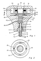
- Fig. 1 einen Längsschnitt eines Einspritzventils für eine Brennkraftmaschine, ausschnittweise,
- Fig. 2 einen Schnitt längs der Linie II-II in Fig. 1,
- Fig. 3 einen Längsschnitt eines Einspritzventils gemäß einem weiteren Ausführungsbeispiel.
- Mit dem in Fig. 1 als Beispiel für ein Zumeßventil zur Dosierung von Flüssigkeiten oder Gasen im Längsschnitt dargestellten Einspritzventil für Kraftstoffeinspritzanlagen in Brennkraftmaschinen können die wesentlichen Größen wie Einspritzmenge, Einspritzrate, Spritzbeginn und Spritzende elektrisch bestimmt werden. Das Einspritzventil weist ein ausschnittweise dargestelltes Ventilgehäuse 1O auf, in welchem eine Stufenbohrung 11 mit im Durchmesser abgestuften Bohrungsabschnitten eingebracht ist. Im unteren brennraumseitigen Bohrungsabschnitt 111 ist ein Ventilkörper 12 mit einer axialen Durchgangsbohrung 13 eingesetzt. Die Durchgangsbohrung 13 mündet in einer Zumeß- oder Ventilöffnung 14, die von einem Ventilsitz 15 ringförmig umgeben ist. Eine in der Durchgangsboh rung 13 geführte Ventilnadel 16 sitzt mit ihrem im Durchmesser vergrößerten Nadelkopf 161 unter Wirkung einer Ventilschließfeder 17 auf dem Ventilsitz 18 auf und dichtet die Ventilöffnung 14 ab. Die Ventilschließfeder 17 stützt sich einerseits am Ventilkörper 12 und andererseits an einem Ringflansch 18 ab, der an dem vom Nadelkopf 161 abgekehrten Ende der Ventilnadel 16 mit dieser starr verbunden ist. Unmittelbar vor dem Ventilsitz 15 ist in der Durchgangsbohrung 13 ein Ringraum 19 vorhanden, der über eine Zulaufbohrung 2O mit einem Kraftstoffzulauf 21 erbunden ist. Um beim Einspritzvorgang einen zu großen Druckabfall zu verhindern ist zweckmäßigerweise zwischen der Zulaufbohrung 2O und dem Kraftstoffzulauf 21 ein Speicher eingeschaltet. Als ein solcher Speicher kann der mittlere Bohrungsabschnitt 112 dienen.
- Im mittleren Bohrungsabschnitt 112 ist ein Piezostack 22 eines piezoelektrischen Stellgliedes 23 angeordnet, dem über elektrische Zuleitungen 24 eine Erregerspannung zugeführt werden kann. Bei Anlegen einer Erregerspannung vergrößert der Piezostack 22 in bekannter Weise seine axiale Länge, wobei die Längenänderung typischerweise etwa 3O µm beträgt. Der üblicherweise aus einzelnen piezoelektrischen Scheiben zusammengesetzte Piezostack 22 ist an seiner einen Stirnseite fest mit dem Ringflansch 18 verbunden und trägt an seiner anderen Stirnseite einen zylinderförmigen Anker 25, der vollständig in das Innere eines hohlzylindrischen Joches 26 mit geringem radialen Spiel eintaucht. Im Joch 26 ist eine ringförmige Erregerspule 27 gehalten. Der Anker 25, das Joch 26 und die Erregerspule 27 bilden eine elektromagnetische Arretiervorrichtung 28, mit welcher der Piezostack 22 während seiner durch die Steuerspannung bewirkten Längenänderung bezüg lich des Ventilgehäuses 1O räumlich festgelegt wird. Die Festlegung des Piezostacks 22 erfolgt durch Wirksamschalten der Arretiervorrichtung 28 zumindest für die Dauer der Ventilöffnung.
- Die elektromagnetische Arretiervorrichtung 28 ist in dem dritten Bohrungsabschnitt 113 untergebracht, wobei das Joch 26 zwischen einer ventilgehäuseseitigen Ringschulter 29 und einer Stützscheibe 3O gehalten ist. Zwischen der Stützscheibe 3O und einer weiteren Ringschulter 3l des Ventilgehäuses 1O ist eine Tellerfeder 32 eingelegt, welche das Joch 26 im Bohrungsabschnitt 113 festlegt.
- Wie in Fig. 2 angedeutet ist, ist das Joch 26 in eine Vielzahl von im Profil U-förmigen Jochblechen 33 unterteilt, die sich bei Strombelegung der Erregerspule 27 auf dem Anker 25 abstützen und ihn damit stationär festklemmen. Anstelle der Jochbleche 33 kann das Joch 26 auch in größere Jochsegmente unterteilt sein, wobei bereits eine Unterteilung des Jochs in zwei halbkreisförmige Ringsegmente genügt. Im letzteren Fall muß jedoch bei der Halterung des Joches 26 zwischen Ringschulter 29 und Stützscheibe 3O für eine geringfügige Radialbewegung des Joches 26 Sorge getragen werden. Ein solches Spiel kann durch entsprechende Bemessung der Tellerfeder 32 gewährleistet werden.
- Die Steuerung der elektromagnetischen Arretiervorrichtung 28 ist so getroffen, daß die Erregerspule 27 ständig mit Erregerstrom beaufschlagt ist und nur nach Einspritzende, also nach Wiederverschließen der Ventilöffnung 14, kurzzeitig stromlos wird. In diesem stromlosen Zustand der Erregerspule 27 ist die Arretiervorrichtung 28 wirkungs los und der Anker 25 kann sich im Joch 26 axial verschieben. Dadurch werden temperaturbedingte Längenänderungen des Piezostacks 22 ebenso wie Fertigungstoleranzen oder Verschleiß kompensiert. Im Moment der Ventilöffnung liegt der Piezostack 22 jedoch gehäuseseitig fest, so daß der von dem Piezostack 22 jeweils zur Verfügung gestellte konstante Stellweg vollständig für den Ventilnadelhub ausgenutzt werden kann.
- Das in Fig. 3 im Längsschnitt zu sehende Einspritzventil unterscheidet sich von dem in Fig. 1 dargestellten Einspritzventil nur durch eine unterschiedliche Ausbildung der elektromagnetischen Arretiervorrichtung 28', so daß mit Bauteilen in Fig. 1 übereinstimmende Bauteile in Fig. 3 mit gleichen Bezugszeichen versehen, jedoch zur Unterscheidung durch einen Beistrich gekennzeichnet sind.
- Der Piezostack 22' ist auf seiner einen Stirnseite 21' wiederum unmittelbar mit der Ventilnadel 15' verbunden und trägt auf seiner anderen Stirnseite eine Ankerplatte 34' mit vergrößertem Durchmesser. Die Ventilschließfeder 17' ist hier zwischen der Ankerplatte 34' und einer gehäuseseitigen Abstützung 35' angeordnet und bewirkt in gleicher Weise ein Aufpressen des Nadelkopfes 161' der Ventilnadel 16' auf den die Ventilöffnung 14' umgebenden Ventilsitz 15'. Das Joch 26' der elektromagnetischen Arretiervorrichtung 28' ist hier hufeisenförmig ausgebildet und trägt auf seinem die beiden Schenkel 261' und 262' einstückig verbindenden Steg 263' die ringförmige Erregerspule 27'. Die Schenkel 261' und 262' sind rechtwinkelig zur Ankerplatte 34' angeordnet. Ihre Stirnflächen 36' bzw. 37' verlaufen unter einem spitzen Neigungswinkel α zur Ankerplatte 34'. Zwischen der Ankerplatte 34' und den Jochschenkeln 261' und 262' ist jeweils ein Keilelement 38' bzw. 39' angeordnet. Jedes Keilelement 38' bzw. 39' weist zwei Keilflächen auf, wovon eine Keilfläche parallel zur Ankerplatte 34' und eine Keilfläche parallel zur Stirnfläche 36' bzw. 37' der Jochschenkel 261' bzw. 262' verläuft. Mit diesen Keilflächen liegt jedes Keilelement 38' bzw. 39' einerseits an der Ankerplatte 34' und andererseits an der Stirnfläche 36' bzw. 37' der Jochschenkel 261' bzw. 262' an. Zwischen den beiden Keilelementen 38' und 39' ist eine Druckfeder 4O' angeordnet, deren Wirkrichtung parallel zur Ankerplatte 34' verläuft. Der Neigungswinkel α der Stirnflächen 36',37' der Jochschenkel 261',262' und damit der Keilwinkel der Keilelemente 38',39' ist größer gewählt als der Haftreibungswinkel ρ .Je mehr der Neigungswinkel α dem Haftreibwinkel ρ angenähert wird, desto kleiner kann der von Joch 26' und Erregerspule 27' gebildete Elektromagnet ausgeführt werden.
- Die Ansteuerung der Erregerspule 27' ist so getroffen, daß sie von kurz nach Spritzende bis kurz vor Spritzbeginn stromlos ist und nur für die Dauer der Ventilöffnung bestromt wird. Dadurch wird wiederum der Piezostack 22 während seiner Erregungsphase gehäuseseitig fixiert. Bei stromlosem Magneten werden Relativbewegungen des aus Ventilnadel 16', Piezostack 22' und Ankerplatte 34' bestehenden einteiligen Ventilbetätigungssystems, die jedoch hauptsächlich durch temperaturbedingte Längenänderungen des Piezostacks 22 hervorgerufen werden, dadurch kompensiert, daß die Keilelemente 38' 39' radial an der Ankerplatte 34' nach außen oder innen verschoben werden. Eine Reduzierung der Länge des Piezostacks 22' bewirkt dabei eine durch die Druckfeder 4O' hervorgerufene Auswanderung der Keilelemente 38',39' nach außen, während eine Vergrößerung der axialen Länge des Piezostacks 22' ein Nachinnengleiten der Keilelemente 38',39' entgegen der Wirkung der Druckfeder 4O' auslöst. In gleicher Weise werden Fertigungstoleranzen oder Verschleiß in dem Betätigungssystem aus Ventilnadel 16', Piezostack 22' und Ankerplatte 34' sowie in den Keilelementen 38',39' und dem Joch 26' ausgeglichen. Auch Fertigungstoleranzen bei der Befestigung des Jochs 26' im Bohrungsabschnitt 113' werden kompensiert.
- Der Vorteil der in Fig. 3 dargestellten elektromagnetischen Arretiervorrichtung 28' gegenüber der in Fig. 1 zu sehenden Arretiervorrichtung 28 liegt darin, daß die Reaktionskräfte des Piezostacks 22 mit einem wesentlich kleineren Elektromagneten aufgefangen werden können. Damit läßt sich das Bauvolumen der elektromagnetischen Arretiervorrichtung 28' sehr klein halten, was einer Integration in das Ventilgehäuse 1O bzw. 1O' entgegenkommt.
Claims (12)
Applications Claiming Priority (2)
| Application Number | Priority Date | Filing Date | Title |
|---|---|---|---|
| DE3533975 | 1985-09-24 | ||
| DE19853533975 DE3533975A1 (de) | 1985-09-24 | 1985-09-24 | Zumessventil zur dosierung von fluessigkeiten oder gasen |
Publications (2)
| Publication Number | Publication Date |
|---|---|
| EP0219669A1 true EP0219669A1 (de) | 1987-04-29 |
| EP0219669B1 EP0219669B1 (de) | 1988-12-07 |
Family
ID=6281763
Family Applications (1)
| Application Number | Title | Priority Date | Filing Date |
|---|---|---|---|
| EP86112343A Expired EP0219669B1 (de) | 1985-09-24 | 1986-09-06 | Zumessventil zur Dosierung von Flüssigkeiten oder Gasen |
Country Status (4)
| Country | Link |
|---|---|
| US (1) | US4750706A (de) |
| EP (1) | EP0219669B1 (de) |
| JP (1) | JPH0745857B2 (de) |
| DE (2) | DE3533975A1 (de) |
Families Citing this family (66)
| Publication number | Priority date | Publication date | Assignee | Title |
|---|---|---|---|---|
| JPH01187363A (ja) * | 1988-01-21 | 1989-07-26 | Toyota Motor Corp | 内燃機関用燃料噴射弁 |
| DE3833093A1 (de) * | 1988-09-29 | 1990-04-12 | Siemens Ag | Fuer verbrennungskraftmaschine vorgesehene kraftstoff-einspritzduese mit steuerbarer charakteristik des kraftstoffstrahls |
| AU4833490A (en) * | 1989-01-11 | 1990-08-13 | Oras Oy | Control valve for a faucet and use of ultrasonic motor |
| JPH0486367A (ja) * | 1990-07-30 | 1992-03-18 | Aisin Seiki Co Ltd | 燃料噴射弁 |
| RU2102626C1 (ru) † | 1992-02-17 | 1998-01-20 | Орбитал Энджин Компани (Аустралиа) Пти. Лимитед | Сопло форсунки |
| US5271226A (en) * | 1992-04-24 | 1993-12-21 | The United States Of America, As Represented By The Secretary Of Commerce | High speed, amplitude variable thrust control |
| US5417142A (en) * | 1992-12-18 | 1995-05-23 | Caterpillar Inc. | Hydraulic amplifier |
| DE4325904C2 (de) * | 1993-08-02 | 1995-07-20 | Daimler Benz Ag | Für eine Dieselbrennkraftmaschine vorgesehene Kraftstoffeinspritzanlage mit einer den Kraftstoff fördernden Hochdruckpumpe in eine gemeinsame Versorgungsleitung (Common-Rail) für alle Einspritzdüsen |
| FR2726603B1 (fr) * | 1994-11-09 | 1996-12-13 | Snecma | Dispositif de controle actif des instabilites de combustion et de decokefaction d'un injecteur de carburant |
| US5645226A (en) * | 1995-02-13 | 1997-07-08 | Siemens Automotive Corporation | Solenoid motion initiator |
| AT1622U1 (de) * | 1995-02-28 | 1997-08-25 | Avl Verbrennungskraft Messtech | Einspritzsystem mit einem einspritzventil für eine selbstzündende brennkraftmaschine |
| GB2303403A (en) * | 1995-07-13 | 1997-02-19 | Ricardo Consulting Eng | Fuel injector with piezo-electric element to vary the size or shape of the ou t passage |
| DE19531652A1 (de) * | 1995-08-29 | 1997-05-07 | Bosch Gmbh Robert | Kraftstoffeinspritzventil für Brennkraftmaschinen |
| DE19534445C2 (de) * | 1995-09-16 | 1998-07-30 | Man Nutzfahrzeuge Ag | Einspritzventil für Brennkraftmaschinen |
| US6026847A (en) * | 1995-10-11 | 2000-02-22 | Reinicke; Robert H. | Magnetostrictively actuated valve |
| US5868375A (en) * | 1995-10-11 | 1999-02-09 | Marotta Scientific Controls, Inc. | Magnetostrictively actuated valve |
| DE19621796A1 (de) * | 1996-05-30 | 1997-12-04 | Nass Magnet Gmbh | Ventil |
| DE19624936A1 (de) * | 1996-06-21 | 1998-01-08 | Focke & Co | Düsenaggregat zum Auftragen von Leim |
| DE19701288C2 (de) * | 1997-01-16 | 1999-10-14 | Daimler Benz Ag | Ventil zur dosierten Abgabe von Fluiden |
| US6091314A (en) * | 1998-06-05 | 2000-07-18 | Siemens Automotive Corporation | Piezoelectric booster for an electromagnetic actuator |
| DE19844837B4 (de) * | 1998-09-30 | 2009-05-07 | Robert Bosch Gmbh | Kraftstoffeinspritzventil für Brennkraftmaschinen |
| DE19848950C2 (de) * | 1998-10-23 | 2003-03-06 | Daimler Chrysler Ag | Vorrichtung zur Konstantsteuerung piezoelektrischer Aktuatoren für Kraftstoffeinspritzsysteme |
| DE19854508C1 (de) * | 1998-11-25 | 2000-05-11 | Siemens Ag | Dosiervorrichtung |
| DE19905340C2 (de) * | 1999-02-09 | 2001-09-13 | Siemens Ag | Verfahren und Anordnung zur Voreinstellung und dynamischen Nachführung piezoelektrischer Aktoren |
| DE19905413A1 (de) | 1999-02-10 | 2000-08-24 | Bosch Gmbh Robert | Injektor mit Piezo-Mehrlagenaktor für Einspritzsysteme |
| DE19906467A1 (de) * | 1999-02-16 | 2000-08-24 | Bosch Gmbh Robert | Injektor mit einem Piezo-Mehrlagenaktor |
| DE19912665A1 (de) * | 1999-03-20 | 2000-09-21 | Bosch Gmbh Robert | Brennstoffeinspritzventil |
| DE19918976A1 (de) | 1999-04-27 | 2000-11-02 | Bosch Gmbh Robert | Brennstoffeinspritzventil und Verfahren zu dessen Betätigung |
| DE19921489A1 (de) * | 1999-05-08 | 2000-11-09 | Bosch Gmbh Robert | Brennstoffeinspritzventil |
| DE19946841A1 (de) * | 1999-09-30 | 2001-05-03 | Bosch Gmbh Robert | Ventil zum Steuern von Flüssigkeiten |
| US6575138B2 (en) * | 1999-10-15 | 2003-06-10 | Westport Research Inc. | Directly actuated injection valve |
| US6836056B2 (en) | 2000-02-04 | 2004-12-28 | Viking Technologies, L.C. | Linear motor having piezo actuators |
| AU2001243481A1 (en) | 2000-03-07 | 2001-09-17 | Viking Technologies, Inc. | Method and system for automatically tuning a stringed instrument |
| US6548938B2 (en) * | 2000-04-18 | 2003-04-15 | Viking Technologies, L.C. | Apparatus having a pair of opposing surfaces driven by a piezoelectric actuator |
| US6717332B2 (en) | 2000-04-18 | 2004-04-06 | Viking Technologies, L.C. | Apparatus having a support structure and actuator |
| US6568602B1 (en) | 2000-05-23 | 2003-05-27 | Caterpillar Inc | Variable check stop for micrometering in a fuel injector |
| US6363913B1 (en) * | 2000-06-09 | 2002-04-02 | Caterpillar Inc. | Solid state lift for micrometering in a fuel injector |
| US6345771B1 (en) | 2000-06-30 | 2002-02-12 | Siemens Automotive Corporation | Multiple stack piezoelectric actuator for a fuel injector |
| IT1320475B1 (it) * | 2000-06-30 | 2003-11-26 | Fiat Ricerche | Attuatore piezoelettrico autocompensato per una valvola di controllo. |
| US6400066B1 (en) | 2000-06-30 | 2002-06-04 | Siemens Automotive Corporation | Electronic compensator for a piezoelectric actuator |
| US6739528B2 (en) | 2000-10-11 | 2004-05-25 | Siemens Automotive Corporation | Compensator assembly having a flexible diaphragm and an internal filling tube for a fuel injector and method |
| US6759790B1 (en) | 2001-01-29 | 2004-07-06 | Viking Technologies, L.C. | Apparatus for moving folded-back arms having a pair of opposing surfaces in response to an electrical activation |
| US6879087B2 (en) * | 2002-02-06 | 2005-04-12 | Viking Technologies, L.C. | Apparatus for moving a pair of opposing surfaces in response to an electrical activation |
| US6499471B2 (en) | 2001-06-01 | 2002-12-31 | Siemens Automotive Corporation | Hydraulic compensator for a piezoelectrical fuel injector |
| US6766965B2 (en) | 2001-08-31 | 2004-07-27 | Siemens Automotive Corporation | Twin tube hydraulic compensator for a fuel injector |
| DE10163731A1 (de) * | 2001-12-21 | 2003-07-10 | Biochip Technologies Gmbh | Piezoaktor |
| WO2004001871A2 (en) * | 2002-06-21 | 2003-12-31 | Viking Technologies, L.C. | Uni-body piezoelectric motor |
| US6811093B2 (en) * | 2002-10-17 | 2004-11-02 | Tecumseh Products Company | Piezoelectric actuated fuel injectors |
| DE112004000605T5 (de) | 2003-04-04 | 2006-03-09 | Viking Technologies, L.C., Sarasota | Vorrichtung und Verfahren zum Optimieren der Arbeit eines Formveränderungsmaterial-Betätigungsgliedprodukts |
| DE10326707B3 (de) * | 2003-06-11 | 2005-01-27 | Westport Germany Gmbh | Ventilvorrichtung und Verfahren zum Einblasen von gasförmigem Kraftstoff |
| US7810743B2 (en) * | 2006-01-23 | 2010-10-12 | Kimberly-Clark Worldwide, Inc. | Ultrasonic liquid delivery device |
| US7819335B2 (en) * | 2006-01-23 | 2010-10-26 | Kimberly-Clark Worldwide, Inc. | Control system and method for operating an ultrasonic liquid delivery device |
| US7744015B2 (en) * | 2006-01-23 | 2010-06-29 | Kimberly-Clark Worldwide, Inc. | Ultrasonic fuel injector |
| US8028930B2 (en) * | 2006-01-23 | 2011-10-04 | Kimberly-Clark Worldwide, Inc. | Ultrasonic fuel injector |
| US8191732B2 (en) * | 2006-01-23 | 2012-06-05 | Kimberly-Clark Worldwide, Inc. | Ultrasonic waveguide pump and method of pumping liquid |
| US7424883B2 (en) * | 2006-01-23 | 2008-09-16 | Kimberly-Clark Worldwide, Inc. | Ultrasonic fuel injector |
| US7735751B2 (en) * | 2006-01-23 | 2010-06-15 | Kimberly-Clark Worldwide, Inc. | Ultrasonic liquid delivery device |
| US7963458B2 (en) * | 2006-01-23 | 2011-06-21 | Kimberly-Clark Worldwide, Inc. | Ultrasonic liquid delivery device |
| FR2908834B1 (fr) * | 2006-11-22 | 2008-12-19 | Renault Sas | Injecteur de carburant pour moteur a combustion interne |
| FR2908835B1 (fr) * | 2006-11-22 | 2008-12-19 | Renault Sas | Injecteur de carburant pour moteur a combustion interne |
| FR2908836B1 (fr) * | 2006-11-22 | 2009-02-13 | Renault Sas | Injecteur de carburant pour moteur a combustion interne |
| FR2916810B1 (fr) * | 2007-05-31 | 2009-08-28 | Renault Sas | Dispositif d'injection de fluide |
| FR2918122B1 (fr) * | 2007-06-27 | 2009-08-28 | Renault Sas | Dispositif d'injection de fluide. |
| FR2929656A1 (fr) * | 2008-04-03 | 2009-10-09 | Renault Sas | Injecteur de fluide, et procede de commande d'un tel injecteur |
| US20100001094A1 (en) * | 2008-07-03 | 2010-01-07 | Caterpillar Inc. | Apparatus and method for cooling a fuel injector including a piezoelectric element |
| US20130068200A1 (en) * | 2011-09-15 | 2013-03-21 | Paul Reynolds | Injector Valve with Miniscule Actuator Displacement |
Citations (6)
| Publication number | Priority date | Publication date | Assignee | Title |
|---|---|---|---|---|
| DE1751543A1 (de) * | 1968-06-15 | 1970-08-27 | Kloeckner Humboldt Deutz Ag | Elektrisch steuerbares Einspritzventil |
| DE1809465A1 (de) * | 1968-11-18 | 1970-09-24 | Kloeckner Humboldt Deutz Ag | Elektrisch steuerbares Einspritzventil |
| DE2917933A1 (de) * | 1978-05-08 | 1979-11-15 | Philips Nv | Regelventil |
| FR2491270A1 (fr) * | 1980-10-01 | 1982-04-02 | Daimler Benz Ag | Organe d'actionnement commande electriquement |
| DE3422935A1 (de) * | 1983-06-20 | 1984-12-20 | Nippon Soken, Inc., Nishio, Aichi | Piezoelektrischer wandler |
| GB2165308A (en) * | 1984-10-09 | 1986-04-09 | Diesel Kiki Co | Fuel injection nozzle for internal combustion engines |
Family Cites Families (4)
| Publication number | Priority date | Publication date | Assignee | Title |
|---|---|---|---|---|
| DE2931874C2 (de) * | 1979-08-06 | 1983-08-04 | Audi Nsu Auto Union Ag, 7107 Neckarsulm | Elektrisch betätigbares Ventil |
| DE3039915A1 (de) * | 1980-10-23 | 1982-05-27 | Robert Bosch Gmbh, 7000 Stuttgart | Elektrisch ansteuerbare ventileinrichtung |
| JPS57136859U (de) * | 1981-02-18 | 1982-08-26 | ||
| DE3237258C1 (de) * | 1982-10-08 | 1983-12-22 | Daimler-Benz Ag, 7000 Stuttgart | Elektrisch vorgesteuerte Ventilanordnung |
-
1985
- 1985-09-24 DE DE19853533975 patent/DE3533975A1/de not_active Withdrawn
-
1986
- 1986-07-29 US US06/893,899 patent/US4750706A/en not_active Expired - Lifetime
- 1986-09-06 DE DE8686112343T patent/DE3661370D1/de not_active Expired
- 1986-09-06 EP EP86112343A patent/EP0219669B1/de not_active Expired
- 1986-09-24 JP JP61223959A patent/JPH0745857B2/ja not_active Expired - Lifetime
Patent Citations (6)
| Publication number | Priority date | Publication date | Assignee | Title |
|---|---|---|---|---|
| DE1751543A1 (de) * | 1968-06-15 | 1970-08-27 | Kloeckner Humboldt Deutz Ag | Elektrisch steuerbares Einspritzventil |
| DE1809465A1 (de) * | 1968-11-18 | 1970-09-24 | Kloeckner Humboldt Deutz Ag | Elektrisch steuerbares Einspritzventil |
| DE2917933A1 (de) * | 1978-05-08 | 1979-11-15 | Philips Nv | Regelventil |
| FR2491270A1 (fr) * | 1980-10-01 | 1982-04-02 | Daimler Benz Ag | Organe d'actionnement commande electriquement |
| DE3422935A1 (de) * | 1983-06-20 | 1984-12-20 | Nippon Soken, Inc., Nishio, Aichi | Piezoelektrischer wandler |
| GB2165308A (en) * | 1984-10-09 | 1986-04-09 | Diesel Kiki Co | Fuel injection nozzle for internal combustion engines |
Also Published As
| Publication number | Publication date |
|---|---|
| DE3661370D1 (en) | 1989-01-12 |
| US4750706A (en) | 1988-06-14 |
| JPH0745857B2 (ja) | 1995-05-17 |
| EP0219669B1 (de) | 1988-12-07 |
| JPS6275065A (ja) | 1987-04-06 |
| DE3533975A1 (de) | 1987-03-26 |
Similar Documents
| Publication | Publication Date | Title |
|---|---|---|
| EP0219669B1 (de) | Zumessventil zur Dosierung von Flüssigkeiten oder Gasen | |
| EP0218895B1 (de) | Zumessventil zur Dosierung von Flüssigkeiten oder Gasen | |
| DE2931874C2 (de) | Elektrisch betätigbares Ventil | |
| DE602005002126T2 (de) | Verstellbares Dosierservoventil eines Einspritzventils | |
| DE3205654A1 (de) | Dosierventil | |
| EP1135595B1 (de) | Ventil zum steuern von flüssigkeiten | |
| EP1567765B1 (de) | Einspritzventil | |
| EP1474603A1 (de) | Brennstoffeinspritzventil | |
| WO2001025613A1 (de) | Brennstoffeinspritzventil | |
| DE19709795A1 (de) | Kraftstoffeinspritzventil für Brennkraftmaschinen | |
| WO2000065224A1 (de) | Brennstoffeinspritzventil und verfahren zu dessen betätigung | |
| EP1472451B1 (de) | Brennstoffeinspritzventil | |
| WO1999018349A1 (de) | Direktgesteuertes einspritzventil, insbesondere kraftstoffeinspritzventil | |
| EP1084344A1 (de) | Brennstoffeinspritzventil | |
| WO2002006663A1 (de) | Brennstoffeinspritzventil | |
| DE19716226C2 (de) | Kraftstoffeinspritzventil für Brennkraftmaschinen | |
| DE3741526C2 (de) | ||
| DE10007733A1 (de) | Einspritzventil | |
| DE10123218A1 (de) | Ventil zum Steuern von Flüssigkeiten | |
| WO2007014733A1 (de) | Kraftstoff-einspritzsystem für eine brennkraftmaschine | |
| EP3559438B1 (de) | Kraftstoffinjektor und dessen verwendung | |
| EP1916414A2 (de) | Kraftstoffinjektor mit Piezoaktor | |
| WO2008061842A1 (de) | Kraftstoffinjektor | |
| EP1144847A1 (de) | Brennstoffeinspritzventil | |
| EP1664525A1 (de) | Dosiervorrichtung |
Legal Events
| Date | Code | Title | Description |
|---|---|---|---|
| PUAI | Public reference made under article 153(3) epc to a published international application that has entered the european phase |
Free format text: ORIGINAL CODE: 0009012 |
|
| AK | Designated contracting states |
Kind code of ref document: A1 Designated state(s): DE FR GB |
|
| 17P | Request for examination filed |
Effective date: 19870909 |
|
| 17Q | First examination report despatched |
Effective date: 19880224 |
|
| GRAA | (expected) grant |
Free format text: ORIGINAL CODE: 0009210 |
|
| AK | Designated contracting states |
Kind code of ref document: B1 Designated state(s): DE FR GB |
|
| REF | Corresponds to: |
Ref document number: 3661370 Country of ref document: DE Date of ref document: 19890112 |
|
| GBT | Gb: translation of ep patent filed (gb section 77(6)(a)/1977) | ||
| ET | Fr: translation filed | ||
| PLBE | No opposition filed within time limit |
Free format text: ORIGINAL CODE: 0009261 |
|
| STAA | Information on the status of an ep patent application or granted ep patent |
Free format text: STATUS: NO OPPOSITION FILED WITHIN TIME LIMIT |
|
| 26N | No opposition filed | ||
| REG | Reference to a national code |
Ref country code: GB Ref legal event code: 746 |
|
| REG | Reference to a national code |
Ref country code: FR Ref legal event code: DL |
|
| PGFP | Annual fee paid to national office [announced via postgrant information from national office to epo] |
Ref country code: GB Payment date: 19980825 Year of fee payment: 13 |
|
| PGFP | Annual fee paid to national office [announced via postgrant information from national office to epo] |
Ref country code: FR Payment date: 19980925 Year of fee payment: 13 |
|
| PGFP | Annual fee paid to national office [announced via postgrant information from national office to epo] |
Ref country code: DE Payment date: 19981130 Year of fee payment: 13 |
|
| PG25 | Lapsed in a contracting state [announced via postgrant information from national office to epo] |
Ref country code: GB Free format text: LAPSE BECAUSE OF NON-PAYMENT OF DUE FEES Effective date: 19990906 |
|
| GBPC | Gb: european patent ceased through non-payment of renewal fee |
Effective date: 19990906 |
|
| PG25 | Lapsed in a contracting state [announced via postgrant information from national office to epo] |
Ref country code: FR Free format text: LAPSE BECAUSE OF NON-PAYMENT OF DUE FEES Effective date: 20000531 |
|
| PG25 | Lapsed in a contracting state [announced via postgrant information from national office to epo] |
Ref country code: DE Free format text: LAPSE BECAUSE OF NON-PAYMENT OF DUE FEES Effective date: 20000701 |
|
| REG | Reference to a national code |
Ref country code: FR Ref legal event code: ST |