EP0220132A2 - Time delayed total-release aerosol dispensers - Google Patents
Time delayed total-release aerosol dispensers Download PDFInfo
- Publication number
- EP0220132A2 EP0220132A2 EP86810452A EP86810452A EP0220132A2 EP 0220132 A2 EP0220132 A2 EP 0220132A2 EP 86810452 A EP86810452 A EP 86810452A EP 86810452 A EP86810452 A EP 86810452A EP 0220132 A2 EP0220132 A2 EP 0220132A2
- Authority
- EP
- European Patent Office
- Prior art keywords
- valve
- sealing material
- container
- actuator
- dispenser
- Prior art date
- Legal status (The legal status is an assumption and is not a legal conclusion. Google has not performed a legal analysis and makes no representation as to the accuracy of the status listed.)
- Granted
Links
Images

Classifications
-
- B—PERFORMING OPERATIONS; TRANSPORTING
- B65—CONVEYING; PACKING; STORING; HANDLING THIN OR FILAMENTARY MATERIAL
- B65D—CONTAINERS FOR STORAGE OR TRANSPORT OF ARTICLES OR MATERIALS, e.g. BAGS, BARRELS, BOTTLES, BOXES, CANS, CARTONS, CRATES, DRUMS, JARS, TANKS, HOPPERS, FORWARDING CONTAINERS; ACCESSORIES, CLOSURES, OR FITTINGS THEREFOR; PACKAGING ELEMENTS; PACKAGES
- B65D83/00—Containers or packages with special means for dispensing contents
- B65D83/14—Containers or packages with special means for dispensing contents for delivery of liquid or semi-liquid contents by internal gaseous pressure, i.e. aerosol containers comprising propellant for a product delivered by a propellant
- B65D83/28—Nozzles, nozzle fittings or accessories specially adapted therefor
-
- B—PERFORMING OPERATIONS; TRANSPORTING
- B65—CONVEYING; PACKING; STORING; HANDLING THIN OR FILAMENTARY MATERIAL
- B65D—CONTAINERS FOR STORAGE OR TRANSPORT OF ARTICLES OR MATERIALS, e.g. BAGS, BARRELS, BOTTLES, BOXES, CANS, CARTONS, CRATES, DRUMS, JARS, TANKS, HOPPERS, FORWARDING CONTAINERS; ACCESSORIES, CLOSURES, OR FITTINGS THEREFOR; PACKAGING ELEMENTS; PACKAGES
- B65D83/00—Containers or packages with special means for dispensing contents
- B65D83/14—Containers or packages with special means for dispensing contents for delivery of liquid or semi-liquid contents by internal gaseous pressure, i.e. aerosol containers comprising propellant for a product delivered by a propellant
- B65D83/75—Aerosol containers not provided for in groups B65D83/16 - B65D83/74
- B65D83/752—Aerosol containers not provided for in groups B65D83/16 - B65D83/74 characterised by the use of specific products or propellants
Definitions
- the main disadvantage of the total-release aerosol dispensers is their immediate actuation which exposes the operator to the contents of the containers.
- USP 3,399,806 Dispensers with delayed opening of a water soluble seal which dissolves when coming in contact with water in the washing machine are described in USP 3,399,806.
- USP 3,800,878 describes a fire extinquisher utilizing an eutectic material in conjunction with an auxiliary seal that isolates the eutectic material from the pressurized fluid of the container. The eutectic material melts in response to an increase in ambient temperature. After complete melting of the eutectic material the auxiliary seal is opened by the pressure within the container thereby permitting release of the fluid. It is rather dangerous to employ together such actuation stimuli as heat and pressure because the heat increases the pressure in the container which may explode.
- the present invention provides a simple, inexpensive, effective, practical and easy to handle means for delayed actuation. It is generally applicable and independent from external factors such as aqueous medium or heat. It provides a time delayed release for all kinds of total-release aerosol dispensers such as foggers, fumigators, insecticidal sprays and bombs, paint capsules, gas bombs, aerosols, oven cleaners, tear gas granades, smoke grenades and explosives, and is particularly appropriate for distribution of pesticides, mote particularly of insecticides.
- the time delayed release of the aerosol dispenser of the invention is obtained with the aid of a material sealing the exit conduit of the dispenser and which material is susceptible to removal by the content of the dispenser's container.
- the sealing material is removed, with delay over a predeterminable period of time by the contents of the container upon mechanical actuation of the valve.
- the sealing material may be in removable association with the valve, valve stem or actuator of said dispenser. After removal of the sealing material the content of the container is released.
- the removal of sealing material may be obtained through the pressure executed by the contents of the dispenser on the sealing material after actuation of the valve, by dissolution of the sealing material in, or disintegration of such sealing material by the contents of the container after actuation of the valve, or by a combination of such factors.
- valves valve stems, actuators and containers of total-release aerosol dispensers are known. Essentially all such dispensers may be adapted in accordance with the present invention.
- the actuator is in the form of a so-called"overcap".
- Overcaps have the dual function of protecting the valve of an aerosol dispenser during storage and of actuating said valve, when inverted and remounted onto the dispenser (see USP 4 426 025).
- the sealing material can be any material which can be placed in the conduit or on the orifice of the valve, valve stem, the actuator or between them and can be removed after actuation of the valve under the influence of the container's content.
- Suitable sealing material may be any material removable under the pressure of the container's content after actuation and may for example be in foil form or have a soft plastic consistency.
- sealing materials suitable for use in the present invention are adhesive or insulation tapes, e.g. tapes known under the trade names Scotch® 810, Scotct® CW 715 44AAV 4152, R-Tape® (CP-PAN) and Silver ClotH® Tape, preferably Scotch® 810 or Silver Cloth® Tape; polyolefins and natural and synthetic resins such as polyvinylchloride, polypropylene, ethylene ethyl acrylates, ethylene vinyl acetate, polyvinyl acetate, polyvinyl alcohol, butyl acrylate, rubbers and elastomers, polyisoprene, polystyrene, polyvinyl acetal, polyvinyl ethyl ether, polyethylene and similar materials, e.g. low density polyethylene foils formulated with paraffin wax, such as the laboratory films available from American Can Corp. under the trade name Parafilm® , preferably such films of 0.010 to 0.015 inches
- the natural and synthetic resins may either be used alone or may be, and preferably are, employed in combination with a plasticizer and optionally other formulating agents such as dyes.
- Sealing materials particularly suitable for use in the present invention are selected from adhesive or insulation tapes, laboratory films such as those known as Parafilm® , and natural or synthetic resins (such as rubbers, polyisoprenes or other aliphatic hydrocarbon resins, wood resins and the like).
- resins particularly suitable for use as sealing agent are wood resins, e.g. wood resins having a softening point of more than 85°C, e.g. in the range of 90 to 105°C, such as low molecular weight aliphatic hydrocarbon resins derived mainly from dienes and other reactive olefin monomers, e.g. those known under the trade name Piccopale® resins (particularly Piccopale 100-SF, available from Hercules Inc., Wilmington); and ethylene vinyl acetate (EVA) based resins, such as the EVA-wax-resin compositions known as Neytac® resins (available from Neville Chemical Company) e.g. Nevtad®100 and Super Nevta® 99.
- wood resins e.g. wood resins having a softening point of more than 85°C, e.g. in the range of 90 to 105°C
- plasticizers suitable for use in the resin combinations are phthalates and adipates, e.g. dibutyl phthalate, dicyclohexyl- phthalate, diethyl phthalate, diisodecylphthalate, dimethyl phthalate, diphenyl phthalate, dioctyl phthalate, dioctyl adipate, butyl benzyl phthalate, diundecyl hthalate, the dialkyl phthtalate known under the trade name Santicizer® 711, the dialkyl adipate known under the trade name Santicizer® 97 and polymeric type plasticizers such as Santicizer® 261, 409, 411, 412,,429, 480, 481, 482, 334 F, 79TM- trimellitate type, particularly suitable plasticizers are dioctyl phthalate (DOP), butyl benzyl phthalate (Santicizer® 160; BBP) and dioct
- the most appropriate sealing materials for use in this invention are laboratory films such as those known as Parafilr® and referred to herein above, particularly such films having a thickness of 0.005 - 0.015, more preferably of 0.01 - 0.015 inches, and resin /plasticizer combinations mixed in a weignt ratio from 50:50 to 90:10, preferably from 70:30 to 90:10.
- Particularly suitable resin/plasticizer combinations comprise from 75-85% by weight of resin and 15 to 25% by weight of plasticizer. They may additionally comprise formulating agents, e.g. 1 part for.100 parts resin/plasticizer combination.
- a preferred example of formulation comprises from 79-82% by weight of resin, 17-22% by weight of plasticizer, the balance being formulating agents such as dyes, e.g. fluorescent dyes such as fluorescent orange, fluorescent yellow, fluorescent blue, fluorescent red and fluorescent black.
- the sealing material can be placed at any place of the exit conduit allowing sealing of the terminal orifice of the aerosol dispenser; it may be placed in the conduit or on the orifice of the valve, valve stem or actuator and in some instances it may also cover the surroundings thereof.
- the valve, valve stem and actuator may have any size or shape; it is only necessary to secure that the amount of sealing material employed is sufficient to completely block the terminal orifice of the aerosol dispenser.
- the sealing material may be introduced at the desired place of the exit conduit (valve-, valve stem-, or actuator orifice or conduit) by known techniques, e.g. manually, by injection, hot molding, dip-coating, coating or other techniques well known in the art.
- Fig. lA is a plan view of the top of the overcap; Fig. 1B is a side sectional view of said overcap and Fig. 1C is enlarged view of the middle section of the overcap in a position in which it is used for delayed actuation.
- the cap which normally serves as a cover for shipping or storing is inverted to actuate the valve of the can. Thereupon the content of the container interacts with the sealing material (by pressure or solvent effects) and begins to actuate such material until it is displaced. Only then the content of the can is released.
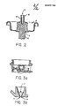
- FIG. 2 is a side sectional view of the aerosol valve assembly showing the stem 6, body of the valve 7, diptube 8 and mounting cup 9.
- buttons-lock actuator Handbook of Aerosol Technology, supra at 111
- seaiing material placed either "on” 10 or "in” 11 the orifice 12 of the actuator.
- Fig. 3A is a side sectional view of the actuator and Fig. 3B is an enlarged view of the middle section thereof.
- the content of the container interacts with the sealing material placed "in” or “on” the orifice of the actuator and begins to affect such material until it is displaced.
- the content of the can is only released with time delay, i.e. after expiration of the time required for the removal of the sealing material.
- the sealing materials are either placed between the valve and the actuator, or built “in” or “on” the actuator or the valve stem of the total-release container.
- the delayed actuation is triggered by engaging the actuator (i.e. by opening the valve).
- the container's content begins then to affect the sealing material, which results finally - after a predeterminable period of time - in the removal of such sealing material and allows thereupon the delayed total-release of the contents of the aerosol dispenser.
- the delay in time depends on the type and amount of sealing material used and on the contents of the container.
- the sealing material can be placed either “in” or “on” the valve, preferably valve stem, into the stem orifice(s), if there are any, in the wall of the stem or in the stem seat (spring cap).
- the details describing the different t ypes of valves, valve stems and various other parts thereof can be found in Handbook of Aerosol Technology, supra, pp. 85-111.
- the sealing material can be placed “in” or “on” the actuator or overcap of any size or shape. Actuators and their functions are generally described in Handbook of Aerosol Technology, supra, pp. 111-114.
- the orifice can be of various shapes and sizes. Such orifices are made in conventional manner.
- the current invention is useful for any kind of administration and total-release of harmful, hazardous, noxious or unpleasant contents of various containers and similar devices to the surrounding environment, which administration could be otherwise harmful, un- : pleasant, impractical or risky to the operator of such device. In such situations, time is needed to get away from the container before it releases its contents.
- the device of this application allows the application of various pesticides, fumigating agents, even hazardous materials which normally cannot be applied without safety hazards, without complicated health protections such as masks, respirators, special clothes, etc. Sometimes, such materials cannot be applied at all without substantial health risk to the operator.
- the operator of a device containing any kind of harmful substance installs the device in the appropriate place, engages the actuator, valve or other triggering unit and leaves.
- the sealing material now comes in contact with the contents of the container which slowly acts onto the sealing material which is susceptible to that content. In due time (controlled by choice of materials, thickness, formulation, dimensions and location), such material fatigues and is displaced thus opening the terminal orifice in the system and allows the content of the container to be released to the environment.
- the device of this invention can be similarly used to activate fire extinguishers in a case of unattended fire, tranquilize wild animals or disturbed or violent people without endangering personnel, administer various detoxicants, disinfectants, anesthetic agents and other agents of a similar type.
- the uses such as a landing area marker or a rescue markersite is also possible.
- This example illustrates a delayed actuation using containers with various contents and unformulated sealing materials susceptible to actuation.
- An adhesive disk of the materials listed below was placed over/on an exit orifice of total release actuator of pressurized insecticide/ solvent containg room fogger. Then the actuator was engaged and the time delay measured in which the actual release from the container occurred.
- the solvent and/or pressure from the fogger was able to disintegrate the tape within 1.5 to 3 seconds.
- Grease was placed in the valve stem of the aerosol container, the valve was opened and the time delay of the actuation was measured.
- the pressure of the aerosol was able to push through the orifice the grease in approximately 1 second.
- a piece of Parafilm® of various thicknesses was placed at the interface of a valve stem and actuator of the generally available insecticidal total-release bomb fogger and the delayed actuation was measured.
- High density polyethylene film (3/1000 inches) was installed at the interface of the valve and actuator of room fogger and the time delay measured.
- Polyethylene material did not rupture, dissolve or disintegrate for at least 60 minutes of the experiment.
- This example illustrates a delayed actuation using various containers, actuating agents and formulated materials susceptible to actuation.
- Combinations of polymer resins/plasticizers have been prepared in the formulations listed below: D.O.A. means dioctyl adipate; FD&C means Food, Drugs & Cosmetics.
- Fogger actuators used in this example were a standard button-lock type (total release * 01-3686) obtained from Precision Valve Corp., Yonkers, N.Y., an overcap (total release overcap # C82-0118-00) obtained from Seaquist, Division of Pittway Corp., Cary, 11., and a fogger actuator cap from Seaquist. ( #means catalogue number.)
- the above formulations produced a small resin worm which passed through the fogger actuator until all of the resin/plasticizer formulation which blocked the orifice was expelled. Due to solvent and/or pressure effects on the resin/plasticizer formulation, the formulation ruptured and allowed for total-release of the contents of the fogger.
- Formulations useful for delayed actuation were prepared by mixing the D.O.A. with fluorescent dye, for example fluorescent orange or fluorescent yellow or with blue, red, black or other dye pigments. The mixture was heated up to 100°C. Then, the polymer resin was added and the whole mixture was heated up to 100°C again until it was molten and homogenous. In the molten stage it was applied to the actuator, valve stem, valve or orifice therein.
- fluorescent dye for example fluorescent orange or fluorescent yellow or with blue, red, black or other dye pigments.
Abstract
Description
- Devices which allow for the total or partial release of an active agent from an aerosol dispenser are known. Examples of these devices may be found in the Handbook of Aerosol Technology by P.S. Sanders, 2nd Ed., page 85, Editor Krieger, 1979).
- The main disadvantage of the total-release aerosol dispensers is their immediate actuation which exposes the operator to the contents of the containers.
- Some attempts for delayed release of the content of various containers were made previously to prevent direct contact of the operator with the content of the container. The resulting devices are mostly applicable and/or suitable for specific purpose only.
- Dispensers with delayed opening of a water soluble seal which dissolves when coming in contact with water in the washing machine are described in USP 3,399,806. USP 3,800,878 describes a fire extinquisher utilizing an eutectic material in conjunction with an auxiliary seal that isolates the eutectic material from the pressurized fluid of the container. The eutectic material melts in response to an increase in ambient temperature. After complete melting of the eutectic material the auxiliary seal is opened by the pressure within the container thereby permitting release of the fluid. It is rather dangerous to employ together such actuation stimuli as heat and pressure because the heat increases the pressure in the container which may explode.
- The present invention provides a simple, inexpensive, effective, practical and easy to handle means for delayed actuation. It is generally applicable and independent from external factors such as aqueous medium or heat. It provides a time delayed release for all kinds of total-release aerosol dispensers such as foggers, fumigators, insecticidal sprays and bombs, paint capsules, gas bombs, aerosols, oven cleaners, tear gas granades, smoke grenades and explosives, and is particularly appropriate for distribution of pesticides, mote particularly of insecticides.
- The time delayed release of the aerosol dispenser of the invention is obtained with the aid of a material sealing the exit conduit of the dispenser and which material is susceptible to removal by the content of the dispenser's container. The sealing material is removed, with delay over a predeterminable period of time by the contents of the container upon mechanical actuation of the valve.
- The sealing material may be in removable association with the valve, valve stem or actuator of said dispenser. After removal of the sealing material the content of the container is released.
- The removal of sealing material may be obtained through the pressure executed by the contents of the dispenser on the sealing material after actuation of the valve, by dissolution of the sealing material in, or disintegration of such sealing material by the contents of the container after actuation of the valve, or by a combination of such factors.
- A wide variety of valves, valve stems, actuators and containers of total-release aerosol dispensers are known. Essentially all such dispensers may be adapted in accordance with the present invention.
- In a preferred embodiment of the invention, the actuator is in the form of a so-called"overcap". Overcaps have the dual function of protecting the valve of an aerosol dispenser during storage and of actuating said valve, when inverted and remounted onto the dispenser (see
USP 4 426 025). - The sealing material can be any material which can be placed in the conduit or on the orifice of the valve, valve stem, the actuator or between them and can be removed after actuation of the valve under the influence of the container's content.
- Suitable sealing material may be any material removable under the pressure of the container's content after actuation and may for example be in foil form or have a soft plastic consistency.
- Examples of sealing materials suitable for use in the present invention are adhesive or insulation tapes, e.g. tapes known under the trade names Scotch® 810, Scotct® CW 715 44AAV 4152, R-Tape® (CP-PAN) and Silver ClotH® Tape, preferably Scotch® 810 or Silver Cloth® Tape; polyolefins and natural and synthetic resins such as polyvinylchloride, polypropylene, ethylene ethyl acrylates, ethylene vinyl acetate, polyvinyl acetate, polyvinyl alcohol, butyl acrylate, rubbers and elastomers, polyisoprene, polystyrene, polyvinyl acetal, polyvinyl ethyl ether, polyethylene and similar materials, e.g. low density polyethylene foils formulated with paraffin wax, such as the laboratory films available from American Can Corp. under the trade name Parafilm® , preferably such films of 0.010 to 0.015 inches thickness; sealants; greases such as silicone grease; waxes.
- The natural and synthetic resins may either be used alone or may be, and preferably are, employed in combination with a plasticizer and optionally other formulating agents such as dyes.
- Sealing materials particularly suitable for use in the present invention are selected from adhesive or insulation tapes, laboratory films such as those known as Parafilm® , and natural or synthetic resins (such as rubbers, polyisoprenes or other aliphatic hydrocarbon resins, wood resins and the like).
- Examples of resins particularly suitable for use as sealing agent are wood resins, e.g. wood resins having a softening point of more than 85°C, e.g. in the range of 90 to 105°C, such as low molecular weight aliphatic hydrocarbon resins derived mainly from dienes and other reactive olefin monomers, e.g. those known under the trade name Piccopale® resins (particularly Piccopale 100-SF, available from Hercules Inc., Wilmington); and ethylene vinyl acetate (EVA) based resins, such as the EVA-wax-resin compositions known as Neytac® resins (available from Neville Chemical Company) e.g. Nevtad®100 and Super Nevta® 99.
- Examples of plasticizers suitable for use in the resin combinations are phthalates and adipates, e.g. dibutyl phthalate, dicyclohexyl- phthalate, diethyl phthalate, diisodecylphthalate, dimethyl phthalate, diphenyl phthalate, dioctyl phthalate, dioctyl adipate, butyl benzyl phthalate, diundecyl hthalate, the dialkyl phthtalate known under the trade name Santicizer® 711, the dialkyl adipate known under the trade name Santicizer® 97 and polymeric type plasticizers such as Santicizer® 261, 409, 411, 412,,429, 480, 481, 482, 334 F, 79TM- trimellitate type, particularly suitable plasticizers are dioctyl phthalate (DOP), butyl benzyl phthalate (Santicizer® 160; BBP) and dioctyl adipate (DOA).
- The most appropriate sealing materials for use in this invention are laboratory films such as those known as Parafilr® and referred to herein above, particularly such films having a thickness of 0.005 - 0.015, more preferably of 0.01 - 0.015 inches, and resin /plasticizer combinations mixed in a weignt ratio from 50:50 to 90:10, preferably from 70:30 to 90:10. Particularly suitable resin/plasticizer combinations comprise from 75-85% by weight of resin and 15 to 25% by weight of plasticizer. They may additionally comprise formulating agents, e.g. 1 part for.100 parts resin/plasticizer combination. A preferred example of formulation comprises from 79-82% by weight of resin, 17-22% by weight of plasticizer, the balance being formulating agents such as dyes, e.g. fluorescent dyes such as fluorescent orange, fluorescent yellow, fluorescent blue, fluorescent red and fluorescent black.
- The sealing material can be placed at any place of the exit conduit allowing sealing of the terminal orifice of the aerosol dispenser; it may be placed in the conduit or on the orifice of the valve, valve stem or actuator and in some instances it may also cover the surroundings thereof. The valve, valve stem and actuator may have any size or shape; it is only necessary to secure that the amount of sealing material employed is sufficient to completely block the terminal orifice of the aerosol dispenser.
- The sealing material may be introduced at the desired place of the exit conduit (valve-, valve stem-, or actuator orifice or conduit) by known techniques, e.g. manually, by injection, hot molding, dip-coating, coating or other techniques well known in the art.
- These and other features and objects of the present invention will become more apparent from the following description taken in conjunction with the accompanying drawings wherein:
- Fig. 1 is a schematic drawing of sectional view, illustrating one preferred embodiment of this invention, i.e. a total release overcap wherein the sealing material is placed either "on" or "in" the orifice of the overcap (serving as actuator).
- Fig. 2 is a schematic drawing of sectional view, illustrating an other preferred embodiment of this invention, i.e. an aerosol valve wherein the sealing material is placed either "on" or "in" the orifice of the valve stem. The actuator is not shown, nor are details drawn from the valve. For more details see for example, Handbook of Aerosol Technology, supra.
- Fig. 3 is a schematic drawing of sectional view, illustrating another preferred embodiment of this invention, i.e. a button-lock actuator wherein the sealing material is placed either "on" or "in" the orifice of the button-lock actuator.
- Referring to Fig. 1, the total release overcap is shown with the sealing material placed either "on" or "in" 2 the
orifice 3 of the overcap. Fig. lA is a plan view of the top of the overcap; Fig. 1B is a side sectional view of said overcap and Fig. 1C is enlarged view of the middle section of the overcap in a position in which it is used for delayed actuation. - In operation, the cap which normally serves as a cover for shipping or storing is inverted to actuate the valve of the can. Thereupon the content of the container interacts with the sealing material (by pressure or solvent effects) and begins to actuate such material until it is displaced. Only then the content of the can is released.
- Referring now to Fig. 2, the aerosol valve (Handbook of Aerosol Technology, supra at 85) is shown with the material susceptible to the container's content placed either "on" 4 or "in" 5 the
valve stem 6 of the aerosol valve assembly. Fig. 2 is a side sectional view of the aerosol valve assembly showing thestem 6, body of the valve 7, diptube 8 and mountingcup 9. - In operation, whenever the actuator (not shown) attached to the valve stem of the container is engaged, the content of the container interacts with the sealing material placed "in" or "on" the valve stem and begins to actuate such material until it is displaced. After removal of the sealing material the content of the can is released.
- Referring now to Fig. 3, the button-lock actuator (Handbook of Aerosol Technology, supra at 111) isshown with the seaiing material placed either "on" 10 or "in" 11 the
orifice 12 of the actuator. - Fig. 3A is a side sectional view of the actuator and Fig. 3B is an enlarged view of the middle section thereof.
- In operation, whenever the actuator attached to the valve stem of the container is engaged, the content of the container interacts with the sealing material placed "in" or "on" the orifice of the actuator and begins to affect such material until it is displaced. The content of the can is only released with time delay, i.e. after expiration of the time required for the removal of the sealing material.
- The sealing materials are either placed between the valve and the actuator, or built "in" or "on" the actuator or the valve stem of the total-release container. The delayed actuation is triggered by engaging the actuator (i.e. by opening the valve). The container's content begins then to affect the sealing material, which results finally - after a predeterminable period of time - in the removal of such sealing material and allows thereupon the delayed total-release of the contents of the aerosol dispenser. The delay in time depends on the type and amount of sealing material used and on the contents of the container.
- The sealing material can be placed either "in" or "on" the valve, preferably valve stem, into the stem orifice(s), if there are any, in the wall of the stem or in the stem seat (spring cap). The details describing the differenttypes of valves, valve stems and various other parts thereof can be found in Handbook of Aerosol Technology, supra, pp. 85-111.
- Similarly, the sealing material can be placed "in" or "on" the actuator or overcap of any size or shape. Actuators and their functions are generally described in Handbook of Aerosol Technology, supra, pp. 111-114.
- The orifice can be of various shapes and sizes. Such orifices are made in conventional manner.
- The current invention is useful for any kind of administration and total-release of harmful, hazardous, noxious or unpleasant contents of various containers and similar devices to the surrounding environment, which administration could be otherwise harmful, un- : pleasant, impractical or risky to the operator of such device. In such situations, time is needed to get away from the container before it releases its contents.
- The device of this application allows the application of various pesticides, fumigating agents, even hazardous materials which normally cannot be applied without safety hazards, without complicated health protections such as masks, respirators, special clothes, etc. Sometimes, such materials cannot be applied at all without substantial health risk to the operator.
- Utilizing this invention, the operator of a device containing any kind of harmful substance installs the device in the appropriate place, engages the actuator, valve or other triggering unit and leaves. The sealing material now comes in contact with the contents of the container which slowly acts onto the sealing material which is susceptible to that content. In due time (controlled by choice of materials, thickness, formulation, dimensions and location), such material fatigues and is displaced thus opening the terminal orifice in the system and allows the content of the container to be released to the environment.
- The device of this invention can be similarly used to activate fire extinguishers in a case of unattended fire, tranquilize wild animals or disturbed or violent people without endangering personnel, administer various detoxicants, disinfectants, anesthetic agents and other agents of a similar type. The uses such as a landing area marker or a rescue markersite is also possible.
- The following examples are intended to illustrate the current invention. They are not to be interpreted as limiting the current invention to the material appearing in the examples.
- This example illustrates a delayed actuation using containers with various contents and unformulated sealing materials susceptible to actuation.
- An adhesive disk of the materials listed below was placed over/on an exit orifice of total release actuator of pressurized insecticide/ solvent containg room fogger. Then the actuator was engaged and the time delay measured in which the actual release from the container occurred.

- Depending on the tape material, the solvent and/or pressure from the fogger was able to disintegrate the tape within 1.5 to 3 seconds.
- Grease was placed in the valve stem of the aerosol container, the valve was opened and the time delay of the actuation was measured.

- The pressure of the aerosol was able to push through the orifice the grease in approximately 1 second. By changing the softness of the grease employed, it is possible to regulate the time delay on release.
- A piece of Parafilm® of various thicknesses was placed at the interface of a valve stem and actuator of the generally available insecticidal total-release bomb fogger and the delayed actuation was measured.

- By changing the thickness of the material, it is possible to regulate the time delay on release.
- High density polyethylene film (3/1000 inches) was installed at the interface of the valve and actuator of room fogger and the time delay measured.

- Polyethylene material did not rupture, dissolve or disintegrate for at least 60 minutes of the experiment.
- Using the procedure of sections I-IV of this example, the time delay of other types of containers and other materials are determined.
- This example illustrates a delayed actuation using various containers, actuating agents and formulated materials susceptible to actuation.
- Combinations of polymer resins/plasticizers (Formulation) have been prepared in the formulations listed below:

- All formulations prepared according to the above schedule were heated until molten, then placed on and over the orifice at the underside of the fogger actuators (20 of each formula). The formulations were allowed to cool to an ambient temperature. Then the actuator was engaged and time delay measured in which the actual release from the container occurred.
- Fogger actuators used in this example were a standard button-lock type (total release * 01-3686) obtained from Precision Valve Corp., Yonkers, N.Y., an overcap (total release overcap # C82-0118-00) obtained from Seaquist, Division of Pittway Corp., Cary, 11., and a fogger actuator cap from Seaquist. ( #means catalogue number.)

- The above formulations produced a small resin worm which passed through the fogger actuator until all of the resin/plasticizer formulation which blocked the orifice was expelled. Due to solvent and/or pressure effects on the resin/plasticizer formulation, the formulation ruptured and allowed for total-release of the contents of the fogger.
-

- These formulations were inserted in an amount from 0.010-0.002 g, into the bottom side orifice of a button-lock actuator and in Seaquist cap actuators. The time delay of total-release was measured after the actuator was engaged.
-

-

- Following the above procedure, the other combination formulations are prepared and tested for time delayed actuation of total-release containers of various types.
- Formulations useful for delayed actuation were prepared by mixing the D.O.A. with fluorescent dye, for example fluorescent orange or fluorescent yellow or with blue, red, black or other dye pigments. The mixture was heated up to 100°C. Then, the polymer resin was added and the whole mixture was heated up to 100°C again until it was molten and homogenous. In the molten stage it was applied to the actuator, valve stem, valve or orifice therein.
Claims (11)
Priority Applications (1)
| Application Number | Priority Date | Filing Date | Title |
|---|---|---|---|
| AT86810452T ATE61309T1 (en) | 1985-10-24 | 1986-10-14 | FULL DELAYED DELIVERY AEROSOL DISPENSER. |
Applications Claiming Priority (2)
| Application Number | Priority Date | Filing Date | Title |
|---|---|---|---|
| US79092585A | 1985-10-24 | 1985-10-24 | |
| US790925 | 1985-10-24 |
Publications (3)
| Publication Number | Publication Date |
|---|---|
| EP0220132A2 true EP0220132A2 (en) | 1987-04-29 |
| EP0220132A3 EP0220132A3 (en) | 1988-03-02 |
| EP0220132B1 EP0220132B1 (en) | 1991-03-06 |
Family
ID=25152142
Family Applications (1)
| Application Number | Title | Priority Date | Filing Date |
|---|---|---|---|
| EP86810452A Expired - Lifetime EP0220132B1 (en) | 1985-10-24 | 1986-10-14 | Time delayed total-release aerosol dispensers |
Country Status (11)
| Country | Link |
|---|---|
| EP (1) | EP0220132B1 (en) |
| JP (1) | JPS62121668A (en) |
| AT (1) | ATE61309T1 (en) |
| AU (1) | AU595252B2 (en) |
| CA (1) | CA1317915C (en) |
| DE (1) | DE3677886D1 (en) |
| ES (1) | ES2020947B3 (en) |
| GR (1) | GR3002021T3 (en) |
| HK (1) | HK6094A (en) |
| IL (1) | IL80396A0 (en) |
| ZA (1) | ZA868128B (en) |
Cited By (2)
| Publication number | Priority date | Publication date | Assignee | Title |
|---|---|---|---|---|
| US6978947B2 (en) | 2003-10-08 | 2005-12-27 | Xianyang Jin | Aerosol spray container with time delayed release actuator |
| US7107986B2 (en) | 1997-06-10 | 2006-09-19 | Glaxo Group Limited | Dispenser with doses' counter |
Citations (2)
| Publication number | Priority date | Publication date | Assignee | Title |
|---|---|---|---|---|
| US3399806A (en) * | 1967-05-01 | 1968-09-03 | Procter & Gamble | Delayed opening dispenser |
| US4426025A (en) * | 1979-06-21 | 1984-01-17 | Seaquist Valve Co. | Continuous spray overcap |
Family Cites Families (3)
| Publication number | Priority date | Publication date | Assignee | Title |
|---|---|---|---|---|
| AU7431081A (en) * | 1980-05-15 | 1982-02-18 | Logan, V.F. | Remote control of spray can |
| US4667855A (en) * | 1980-11-25 | 1987-05-26 | W. R. Grace & Co. | Method of reducing failure of pressurized container valves |
| US4478044A (en) * | 1981-08-05 | 1984-10-23 | Enviro-Spray Systems, Inc. | Inflatable pouch and method of manufacture |
-
1986
- 1986-10-14 ES ES86810452T patent/ES2020947B3/en not_active Expired - Lifetime
- 1986-10-14 AT AT86810452T patent/ATE61309T1/en not_active IP Right Cessation
- 1986-10-14 DE DE8686810452T patent/DE3677886D1/en not_active Expired - Lifetime
- 1986-10-14 EP EP86810452A patent/EP0220132B1/en not_active Expired - Lifetime
- 1986-10-22 AU AU64351/86A patent/AU595252B2/en not_active Ceased
- 1986-10-22 IL IL80396A patent/IL80396A0/en not_active IP Right Cessation
- 1986-10-23 CA CA000521227A patent/CA1317915C/en not_active Expired - Fee Related
- 1986-10-23 JP JP61253524A patent/JPS62121668A/en active Pending
- 1986-10-24 ZA ZA868128A patent/ZA868128B/en unknown
-
1991
- 1991-05-29 GR GR91400699T patent/GR3002021T3/en unknown
-
1994
- 1994-01-20 HK HK60/94A patent/HK6094A/en unknown
Patent Citations (2)
| Publication number | Priority date | Publication date | Assignee | Title |
|---|---|---|---|---|
| US3399806A (en) * | 1967-05-01 | 1968-09-03 | Procter & Gamble | Delayed opening dispenser |
| US4426025A (en) * | 1979-06-21 | 1984-01-17 | Seaquist Valve Co. | Continuous spray overcap |
Cited By (3)
| Publication number | Priority date | Publication date | Assignee | Title |
|---|---|---|---|---|
| US7107986B2 (en) | 1997-06-10 | 2006-09-19 | Glaxo Group Limited | Dispenser with doses' counter |
| US8245704B2 (en) | 1997-06-10 | 2012-08-21 | Glaxo Group Limited | Dispenser with doses' counter |
| US6978947B2 (en) | 2003-10-08 | 2005-12-27 | Xianyang Jin | Aerosol spray container with time delayed release actuator |
Also Published As
| Publication number | Publication date |
|---|---|
| ES2020947B3 (en) | 1991-10-16 |
| HK6094A (en) | 1994-01-28 |
| ZA868128B (en) | 1988-06-29 |
| JPS62121668A (en) | 1987-06-02 |
| CA1317915C (en) | 1993-05-18 |
| EP0220132B1 (en) | 1991-03-06 |
| AU6435186A (en) | 1987-04-30 |
| EP0220132A3 (en) | 1988-03-02 |
| AU595252B2 (en) | 1990-03-29 |
| GR3002021T3 (en) | 1992-12-30 |
| DE3677886D1 (en) | 1991-04-11 |
| IL80396A0 (en) | 1987-01-30 |
| ATE61309T1 (en) | 1991-03-15 |
Similar Documents
| Publication | Publication Date | Title |
|---|---|---|
| US3172568A (en) | Pressurized dispensing device | |
| EP1105323B1 (en) | Actuator system for spraying a formulation onto a host | |
| US3207386A (en) | Aerosol dispenser producing non-flammable spray with fluid system having a flammable propellant | |
| US3995778A (en) | Aerosol dispensing device | |
| US4083954A (en) | Aerosol composition | |
| US3159535A (en) | Aerosol compositions | |
| KR870700205A (en) | Elastomeric Controlled Release Formulations and Products Containing the Same | |
| US4823986A (en) | Delayed time actuation for total-release containers and similar devices | |
| US2987439A (en) | Method of applying an aerosol to the eye | |
| EP0220132B1 (en) | Time delayed total-release aerosol dispensers | |
| CA2427909C (en) | Non-flammable aerosol insecticidal compositions | |
| EP2987404A1 (en) | Injection device for powdered drugs and injection method for powdered drugs | |
| JP2002308704A (en) | Aerosol composition | |
| KR950005129B1 (en) | Time delayed total-release aerosol dispensers | |
| JPH02101001A (en) | Composition and method for preventing and controlling invasion of flea and mite in animal | |
| WO2006002354A1 (en) | Time delay and indicator actuator assembly for aerosol containers | |
| US3129855A (en) | Aerosol package | |
| US3244331A (en) | Disposable single charge aerosol capsule | |
| JP4535673B2 (en) | Efficacy indicator of aerosol agent containing volatile drug, and medicinal effect indication method in environmental atmosphere using the same | |
| JPH11221499A (en) | Jetting aperture of aerosol apparatus | |
| JPS5944281B2 (en) | Space aerosol insecticide | |
| GB1091374A (en) | Aerosol insecticidal,bactericidal,fungicidal and/or deodorising compositions | |
| JPH01180806A (en) | Hydrogen phosphide generating harmful insect control agent and its production | |
| JPH0232190A (en) | Aerosol product | |
| JPH05286805A (en) | Aerosol composition for control of insect pest |
Legal Events
| Date | Code | Title | Description |
|---|---|---|---|
| PUAI | Public reference made under article 153(3) epc to a published international application that has entered the european phase |
Free format text: ORIGINAL CODE: 0009012 |
|
| 17P | Request for examination filed |
Effective date: 19861016 |
|
| AK | Designated contracting states |
Kind code of ref document: A2 Designated state(s): AT BE CH DE ES FR GB GR IT LI NL SE |
|
| PUAL | Search report despatched |
Free format text: ORIGINAL CODE: 0009013 |
|
| AK | Designated contracting states |
Kind code of ref document: A3 Designated state(s): AT BE CH DE ES FR GB GR IT LI NL SE |
|
| 17Q | First examination report despatched |
Effective date: 19900119 |
|
| GRAA | (expected) grant |
Free format text: ORIGINAL CODE: 0009210 |
|
| AK | Designated contracting states |
Kind code of ref document: B1 Designated state(s): AT BE CH DE ES FR GB GR IT LI NL SE |
|
| REF | Corresponds to: |
Ref document number: 61309 Country of ref document: AT Date of ref document: 19910315 Kind code of ref document: T |
|
| REF | Corresponds to: |
Ref document number: 3677886 Country of ref document: DE Date of ref document: 19910411 |
|
| ITF | It: translation for a ep patent filed |
Owner name: SANDOZ PRODOTTI FARMAC. S.P.A. |
|
| ET | Fr: translation filed | ||
| PLBE | No opposition filed within time limit |
Free format text: ORIGINAL CODE: 0009261 |
|
| STAA | Information on the status of an ep patent application or granted ep patent |
Free format text: STATUS: NO OPPOSITION FILED WITHIN TIME LIMIT |
|
| 26N | No opposition filed | ||
| REG | Reference to a national code |
Ref country code: GR Ref legal event code: FG4A Free format text: 3002021 |
|
| EAL | Se: european patent in force in sweden |
Ref document number: 86810452.2 |
|
| PGFP | Annual fee paid to national office [announced via postgrant information from national office to epo] |
Ref country code: GB Payment date: 19950907 Year of fee payment: 10 |
|
| PGFP | Annual fee paid to national office [announced via postgrant information from national office to epo] |
Ref country code: SE Payment date: 19950913 Year of fee payment: 10 |
|
| PGFP | Annual fee paid to national office [announced via postgrant information from national office to epo] |
Ref country code: NL Payment date: 19950922 Year of fee payment: 10 Ref country code: BE Payment date: 19950922 Year of fee payment: 10 |
|
| PGFP | Annual fee paid to national office [announced via postgrant information from national office to epo] |
Ref country code: FR Payment date: 19950925 Year of fee payment: 10 Ref country code: ES Payment date: 19950925 Year of fee payment: 10 |
|
| PGFP | Annual fee paid to national office [announced via postgrant information from national office to epo] |
Ref country code: AT Payment date: 19951010 Year of fee payment: 10 |
|
| PGFP | Annual fee paid to national office [announced via postgrant information from national office to epo] |
Ref country code: DE Payment date: 19951013 Year of fee payment: 10 |
|
| PGFP | Annual fee paid to national office [announced via postgrant information from national office to epo] |
Ref country code: GR Payment date: 19951031 Year of fee payment: 10 |
|
| PGFP | Annual fee paid to national office [announced via postgrant information from national office to epo] |
Ref country code: CH Payment date: 19960112 Year of fee payment: 10 |
|
| PG25 | Lapsed in a contracting state [announced via postgrant information from national office to epo] |
Ref country code: GB Effective date: 19961014 Ref country code: AT Effective date: 19961014 |
|
| PG25 | Lapsed in a contracting state [announced via postgrant information from national office to epo] |
Ref country code: SE Effective date: 19961015 Ref country code: ES Free format text: LAPSE BECAUSE OF THE APPLICANT RENOUNCES Effective date: 19961015 |
|
| PG25 | Lapsed in a contracting state [announced via postgrant information from national office to epo] |
Ref country code: LI Effective date: 19961031 Ref country code: CH Effective date: 19961031 Ref country code: BE Effective date: 19961031 |
|
| BERE | Be: lapsed |
Owner name: SANDOZ A.G. Effective date: 19961031 |
|
| PG25 | Lapsed in a contracting state [announced via postgrant information from national office to epo] |
Ref country code: GR Free format text: THE PATENT HAS BEEN ANNULLED BY A DECISION OF A NATIONAL AUTHORITY Effective date: 19970430 |
|
| PG25 | Lapsed in a contracting state [announced via postgrant information from national office to epo] |
Ref country code: NL Effective date: 19970501 |
|
| REG | Reference to a national code |
Ref country code: GR Ref legal event code: MM2A Free format text: 3002021 |
|
| GBPC | Gb: european patent ceased through non-payment of renewal fee |
Effective date: 19961014 |
|
| REG | Reference to a national code |
Ref country code: CH Ref legal event code: PL |
|
| PG25 | Lapsed in a contracting state [announced via postgrant information from national office to epo] |
Ref country code: FR Effective date: 19970630 |
|
| NLV4 | Nl: lapsed or anulled due to non-payment of the annual fee |
Effective date: 19970501 |
|
| PG25 | Lapsed in a contracting state [announced via postgrant information from national office to epo] |
Ref country code: DE Effective date: 19970701 |
|
| EUG | Se: european patent has lapsed |
Ref document number: 86810452.2 |
|
| REG | Reference to a national code |
Ref country code: FR Ref legal event code: ST |
|
| REG | Reference to a national code |
Ref country code: ES Ref legal event code: FD2A Effective date: 19991007 |
|
| PG25 | Lapsed in a contracting state [announced via postgrant information from national office to epo] |
Ref country code: IT Free format text: LAPSE BECAUSE OF NON-PAYMENT OF DUE FEES;WARNING: LAPSES OF ITALIAN PATENTS WITH EFFECTIVE DATE BEFORE 2007 MAY HAVE OCCURRED AT ANY TIME BEFORE 2007. THE CORRECT EFFECTIVE DATE MAY BE DIFFERENT FROM THE ONE RECORDED. Effective date: 20051014 |