EP0221007A1 - Thin-needle biopsy cannule with a mandrel - Google Patents
Thin-needle biopsy cannule with a mandrel Download PDFInfo
- Publication number
- EP0221007A1 EP0221007A1 EP86730179A EP86730179A EP0221007A1 EP 0221007 A1 EP0221007 A1 EP 0221007A1 EP 86730179 A EP86730179 A EP 86730179A EP 86730179 A EP86730179 A EP 86730179A EP 0221007 A1 EP0221007 A1 EP 0221007A1
- Authority
- EP
- European Patent Office
- Prior art keywords
- stylet
- cut
- cannula
- biopsy
- biopsy cannula
- Prior art date
- Legal status (The legal status is an assumption and is not a legal conclusion. Google has not performed a legal analysis and makes no representation as to the accuracy of the status listed.)
- Granted
Links
Images

Classifications
-
- A—HUMAN NECESSITIES
- A61—MEDICAL OR VETERINARY SCIENCE; HYGIENE
- A61B—DIAGNOSIS; SURGERY; IDENTIFICATION
- A61B10/00—Other methods or instruments for diagnosis, e.g. instruments for taking a cell sample, for biopsy, for vaccination diagnosis; Sex determination; Ovulation-period determination; Throat striking implements
- A61B10/02—Instruments for taking cell samples or for biopsy
- A61B10/0233—Pointed or sharp biopsy instruments
- A61B10/0283—Pointed or sharp biopsy instruments with vacuum aspiration, e.g. caused by retractable plunger or by connected syringe
Abstract
Description
Die Erfindung betrifft eine Biopsiekanüle mit kleinem Anschliffwinkel mit einer umlaufenden Schneidkante, mit einem über dem Schliff der Kanüle herausragenden Mandrin, dessen Schliffwinkel und Orientierung dem des Kanülenschliffs entsprechen und mit Hinterschliff-Facetten im Bereich der Schneidkante der Biopsiekanüle.The invention relates to a biopsy cannula with a small bevel with a circumferential cutting edge, with a stylet protruding above the bevel of the cannula, the bevel angle and orientation of which correspond to that of the cannula, and with relief cut facets in the area of the cutting edge of the biopsy cannula.
Eine Biopsiekanüle mit Mandrin ist aus dem DE-GM 79 14 565 bekannt, bei dem der Mandrin mit einer längsverlaufenden Probenkerbe versehen ist. Zur Probengewinnung wird die Schneidkanüle längs des festgehaltenen Mandrin nach vorne bewegt; die in den Probenkerb eingedrückte Gewebemasse wird dabei durch die Schneidkante der Kanüle aus dem Zielgebiet abgetrennt. Durch Herausziehen des Mandrins wird die Probe aus dem Körper entfernt, die Schneidkanüle kann dabei liegen bleiben. Ebenso kann das geschlossene System herausgezogen werden.A biopsy cannula with stylet is known from DE-GM 79 14 565, in which the stylet is provided with a longitudinal sample notch. The cutting cannula is moved forward along the fixed stylet to obtain samples; the tissue mass pressed into the sample notch is separated from the target area by the cutting edge of the cannula. The sample is removed from the body by pulling out the stylet, the cutting cannula can remain there. The closed system can also be pulled out.
Weitere Biopsiekanülen sind als Produkte der Fa. B. Braun Melsungen bekannt; es handelt sich hier ebenso wie bei der bekannten Kanüle der Firma TSK aus Japan um Kanülen mit Menghini-Schliffen. Diese erfahren durch Variation des Schliffwinkels und der symmetrischen Mandrinspitze (siehe Prospektblatt der Fa. Paul Stocton, Dallas) unterschiedliche Gestaltungen, damit aber auch unterschiedliche Kräfte beim Eindringen in das Gewebe. Ebenso wird eine unterschiedliche Qualität des entnommenen Gewebes gefunden.Additional biopsy cannulas are known as products from B. Braun Melsungen; Just like the well-known cannula from TSK from Japan, these are cannulas with Menghini cuts. By varying the grinding angle and the symmetrical stylet tip (see brochure from Paul Stocton, Dallas), they experience different designs, but also different forces when penetrating the tissue. A different quality of the removed tissue is also found.
Ein sehr flacher Menghini-Schliff ist in Med. Welt 22, 1869 (1971), Heft 47 beschrieben. Des weiteren ist im Produkt der Fa. B. Braun Melsungen, Art. Nr. 481014/7 mit der Charge 17080 I 2412 eine Schneidkante mit zwei Facetten vorhanden, welche aber nicht vollständig bis zum Innenlumen geschliffen sind.A very flat Menghini cut is described in Med. Welt 22, 1869 (1971), No. 47. Furthermore, the product from B. Braun Melsungen, Art. No. 481014/7 with batch 17080 I 2412 has a cutting edge with two facets, which are not completely ground down to the inner lumen.
Ein Flachschliffmandrin, welcher weiter als der Biopsieschneidschliff durch diesen nach vorne ragt, wird in der US-PS 4 314 565 für Knochenmarkbiopsien beschrieben. Er soll dort dazu dienen, das Eindringen von Kochenspänen in das Innenlumen zu verhindern. Die Schlifforientierung und Schräge dieses Mandrins ist die gleiche wie jene des Biopsiekanülenschliffs.A flat-section stylet, which projects further than the biopsy cutting section through it, is described in US Pat. No. 4,314,565 for bone marrow biopsies. It is designed to prevent cooking chips from entering the inner lumen. The cut orientation and slope of this stylet is the same as that of the biopsy cannula cut.
Nachteilig bei allen vorgenannten Schliffversionen bzw. Kanülen-Mandrin Kombinationen ist, daß sie nicht in der Lage sind, sämtliche Aufgaben gleichzeitig zu lösen, die sich an eine Kanüle zur ultraschallgesteuerten oder -kontrollierten Punktion zur Gewebebiopsie stellen.A disadvantage of all of the aforementioned versions of cuts or cannula-stylet combinations is that they are unable to simultaneously solve all of the tasks that arise from a cannula for ultrasound-controlled or -controlled puncture for tissue biopsy.
Entweder ist die Kraft zum Eindringen durch Facien, Haut oder Organkapseln zu hoch (konischer Mandrin), oder deren Ultraschallsichtbarkeit ist zu schlecht (reine Menghini-Rundschliffe), oder es wird zwischen Mandrin und Schneidkante falsches Gewebe aus zuvor durchdrungenen Gewebeschichten abgeschnitten, was die histologische Diagnoseverfälscht, oder dem Patienten werden so große Schmerzen zugefügt, daß er nicht ruhig liegen bleibt und die Kanüle an eine falsche Stelle abrutscht.Either the force to penetrate through facies, skin or organ capsules is too high (conical stylet), or their ultrasound visibility is too poor (pure Menghini round cuts), or there is a difference between stylet and cutting edge of false tissue is cut from previously penetrated layers of tissue, which falsifies the histological diagnosis, or the patient is inflicted with such great pain that he does not remain still and the cannula slips to an incorrect location.
Aufgabe der vorliegenden Erfindung ist es, eine Kanüle zu schaffen, die eine genaue Probeentnahme aus einem sonographisch erfaßten Zielgebiet ermöglicht und mit der Komplikation vermieden werden können.The object of the present invention is to provide a cannula which enables precise sampling from a sonographically recorded target area and which can be avoided with the complication.
Gelöst wird diese Aufgabe dadurch, daß die Hinterschliff-Facetten der Schneidkante der Biopsie-Kanüle bis an ihr Innenlumen herangeschliffen sind, daß der Schliff des Mandrins als Facettenschliff ausgebildet ist, daß das Hinterende des Mandrins mit der Kolbenstange einer Aspirationsspritze, auf welche die Biopsiekanüle montiert ist, verbunden und gegen Verdrehung gesichert ist, und daß beide Schliffe im Längsabstand so angeordnet sind, daß sie eine funktionelle Einheit bilden. Bei einer anderen Ausführung ist es vorgesehen, daß der Schliff des Mandrins als asymmetrischer Trokarschliff ausgebildet ist.This object is achieved in that the relief cut facets of the cutting edge of the biopsy cannula are ground up to their inner lumen, that the cut of the stylet is designed as a facet cut, that the rear end of the stylet with the piston rod of an aspiration syringe on which the biopsy cannula is mounted is connected and secured against rotation, and that both cuts are arranged in the longitudinal distance so that they form a functional unit. In another embodiment, it is provided that the cut of the stylet is designed as an asymmetrical trocar cut.
Durch die kurz hintereinander folgende Anordnung beider Schliffe und die Befestigung des Mandrins an der nicht verdrehbaren Kolbenstange der Aspirationsspritze entsteht eine funktionelle Einheit zur Penetration ins Zielorgan, die leicht, ohne Schmerzen für den Patienten und ohne das vorherige Abschneiden von falschen Gewebe ablauft.The arrangement of the two cuts in quick succession and the attachment of the stylet to the non-rotatable piston rod of the aspiration syringe create a functional unit for penetration into the target organ, which runs easily, without pain for the patient and without first cutting off the wrong tissue.
Die eigentliche Gewebsbiopsie, die dann im Zielorgan stattfindet, geschieht unter Vakuum mit zurückgezogenem Mandrin, wobei jetzt die beiden scharfen Facetten des Menghini-Schliffs zusammen mit der umlaufenden Schneidkante eine schnelle und wenig gewebszerstörende Biopsie erlauben. Das teilweise beobachtete bisherige Zerfetzen von Zellen im Randbezirk des Biopsiezylinders, das eine Verschlechterung der Ausbeute bedeutet, wird auf diese Weise ebenso vermieden wie die Ausweichbewegung des Zielgebiets bei Punktionen an locker beweglichen Organgen. Der zurückgezogene Mandrin verhindert ebenso das Weiterrutschen der Biopsiezylinder in die Spritze.The actual tissue biopsy, which then takes place in the target organ, is performed under vacuum with the stylet withdrawn, whereby the two sharp facets of the Menghini cut together with the circumferential cutting edge allow a quick and less tissue-destructive biopsy. The partially observed shredding of cells in the peripheral area of the biopsy cylinder, which means a deterioration in the yield, is avoided in this way, as is the evasive movement of the target area in the case of punctures on loosely mobile organs. The retracted stylet also prevents the biopsy cylinders from slipping into the syringe.
Üblicherweise wird eine derartige Biopsie unter Zuhilfenahme von Ultraschall durchgeführt. Der untersuchende Arzt hält dabei in einer Hand den Schallkopf des Ultraschallgeräts und verfolgt auf einem Monitor das zu untersuchende Zielgebiet. Mit der anderen Hand kann die an einem Spritzenhalter adaptierte Aspirationsspritze mit der erfindungsgemäßen Biopsiekanüle in das Zielgebiet geführt werden.Such a biopsy is usually carried out with the aid of ultrasound. The examining doctor holds the transducer of the ultrasound device in one hand and tracks the target area to be examined on a monitor. With the other hand, the aspiration syringe adapted to a syringe holder can be guided into the target area with the biopsy cannula according to the invention.
Die Mandrinspitze soll dabei im Ultraschall gut sichtbar sein und eine gute Richtungstreue aufweisen um zu gewährleisten, daß auch tatsächlich das anvisierte Zielgebiet getroffen wird. Dazu wird der Mandrin mit dem Spritzenhalter zurückgezogen und die Kanüle kurz in das Zielgebiet vorgestoßen. Durch den mit einem Hinterschliff geschärften Menghini-Schliff der Kanüle in Verbindung mit dem Vakuum, das durch das Zurückziehen des Mandrins und des Kolbens in der Kanüle erzeugt wird, wird ein Gewebezylinder gewonnen. Infolge der verhesserten Schneideigenschaften der Kanüle können auch noch bei sehr kleinen Innendurchmessern zusammenhängende Gewebszylinder gewonnen werden. Mit herkömmlichen Schliffen würde hier nur noch eine Zellschmiere gewonnen werden.The stylet tip should be clearly visible on ultrasound and have good directional stability to ensure that the targeted area is actually hit. To do this, the stylet is withdrawn with the syringe holder and the cannula is briefly pushed into the target area. Due to the Menghini sharpening of the cannula, which is sharpened with a relief, in connection with the vacuum that a tissue cylinder is obtained by withdrawing the stylet and the piston in the cannula. As a result of the improved cutting properties of the cannula, connected tissue cylinders can still be obtained even with very small inner diameters. With conventional cuts, only a cell smear would be obtained here.
Während der Biopsie sollte der Patient die Luft anhalten, um innere Verletzungen zu vermeiden. Da eine Biopsie mit der vorgeschlagenen Feinnadel-Biopsiekanüle nur ca. 1 his 3 Sekunden dauert, ist ein ruhiges Verhalten des Patienten problemlos möglich.During the biopsy, the patient should hold their breath to avoid internal injury. Since a biopsy with the proposed fine needle biopsy cannula only takes about 1 to 3 seconds, calm behavior of the patient is possible without any problems.
Die ausgestanzte Probe kann außerhalb des Körpers durch das Verschieben des Mandrins ausgestrichen werden. Dabei wird diese Probe nicht zerstört und es wird keine mit Fremdgewebe durchsetzte Zellprobe sondern ein größerer Gewebezylinder gewonnen, der ausschließlich aus Gewebe des Zielgebiets besteht. Eine solche Gewebeprobe kann histologisch beurteilt werden.The punched-out sample can be spread out outside the body by moving the stylet. This sample is not destroyed and no cell sample interspersed with foreign tissue is obtained, but rather a larger tissue cylinder that consists exclusively of tissue from the target area. Such a tissue sample can be assessed histologically.
Durch die Biopsie mit einem Kanülendurchmesser im Feinnadelbereich wird die Gefahr des Traumas erheblich verringert, der Patient hat weniger Schmerzempfinden, die Folgereaktionen des vegetativen Nervensystems werden verringert, ebenso die Schmerzabwehrbewegungen des Patienten.The biopsy with a cannula diameter in the fine needle area considerably reduces the risk of trauma, the patient has less pain sensation, the subsequent reactions of the vegetative nervous system are reduced, as is the patient's pain defense movements.
Durch die Gleichsinnigkeit der spitzen Mandrin- und Kanülen schräganschliffe, die durch eine Verdrehsicherung sichergestellt ist, wird gewährleistet, daß der Mandrin durch das Gewebe eine Bahn vorschneidet, in der die nachfolgende Stanzkanüle geführt wir. Durch diesen Schnitt kann das Gewebe sich nicht so stark verdichten, daß die nachfolgende Schneidkante blockiert wird. Auf diese Weise ist sichergestellt, daß nur Gewebe aus dem Zielgebiet entnommen wird. Durch die Befestigung des Mandrins am Kolben kann dieser schnell und mit einem Zug zurückgezogen und die Schneidkante der Stanzkanüle zur eigentlichen Probeentnahme freigegeben werden. Dadurch ist eine schnelle und sichere Handhabung möglich. Auch können aus locker aufgehängten Organen Proben entnommen werden, ohne daß diese ausweichen können. Die hohe Auflösung moderner Ultraschallgeräte läßt immer häufer Organveränderungen erkennen, die einer weiteren Abklärung bedürfen. Die Entnahme von Gewebeproben mittels perkutaner Feinnadelpunktion mit der erfindungsgemäßen Kanüle ist dabei risikoarm möglich. Die scharfe Mandrinspitze überragt die Schneidkante der Kanüle um ca. 2 mm. Dabei folgt die Kanülen-Schneidkante der am äußeren Umfang verlaufenden Mandrin-Schneidkante, wodurch beide Schneidkanten eine funktionell einheitliche Schneidkante bilden. Diese funktionell einheitliche, spitze und sehr scharfe Schneidkante ermöglicht ein glattes Durchtrennen der Epidermis ohne vorherige Stichinzision. Die unmittelbar folgende Biopsiekanüle findet in der vom Mandrin vorgeschnittenen Bahn praktisch keinen Widerstand. Hat die sonographisch gut sichtbare Nadelspitze den Punktionsort erreicht, so wird der am Spritzenkolben befestigte Mandrin zurückgezogen und gleichzeitig ein Unterdruck aufgebaut. Der Mandrin bewirkt nun als Stopsonde, der das Verschleppen des aspirierten Materials in der Spritze verhindert.Due to the similarity of the pointed stylet and cannulas bevel cuts, which are ensured by an anti-twist device, ensure that the stylet cuts a path through the tissue in which the following punch cannula is guided. This cut means that the tissue cannot compact itself so much that the subsequent cutting edge is blocked. This ensures that only tissue is removed from the target area. By attaching the stylet to the plunger, it can be pulled back quickly and with one pull and the cutting edge of the punch cannula can be released for the actual sampling. This enables quick and safe handling. Samples can also be taken from loosely suspended organs without these being able to escape. The high resolution of modern ultrasound devices increasingly reveals organ changes that require further clarification. The taking of tissue samples by means of percutaneous fine needle puncture with the cannula according to the invention is possible with little risk. The sharp stylet tip protrudes about 2 mm from the cutting edge of the cannula. The cannula cutting edge follows the stylet cutting edge running on the outer circumference, as a result of which both cutting edges form a functionally uniform cutting edge. This functionally uniform, pointed and very sharp cutting edge enables the epidermis to be cut smoothly without prior incision. The immediately following biopsy cannula finds practically no resistance in the path precut from the stylet. If the needle tip, which is clearly visible sonographically, has reached the puncture site, then the stylet attached to the syringe plunger is withdrawn and at the same time a vacuum is built up. The stylet now acts as a stop probe, which prevents the aspirated material from being carried over into the syringe.
Weitere vorteilhafte Maßnahmen sind in den Unteransprüchen beschrieben. Die Erfindung ist in der beiliegenden Zeichnung dargestellt und wird nachfolgend näher beschrieben; es zeigt:
- Fig. 1 die Seiten ansicht einer Biopsiekanüle mit einem Schräganschliff mit Hinterschliff und einem Mandrin mit gleichsinnig orientiertem Schräganschliff mit Facettenschliff;
- Fig 2 die Rückansicht einer Biopsiekanüle nach der Fig. 1 mit Schräganschliff, Hinterschliff und Mandrin;
- Fig. 3 die Vorderansicht einer Biopsiekanüle nach Fig. 1 mit einem Mandrin mit Längsbohrung und Facettenschliff;
- Fig. 4 die Vorderansicht einer Biopsiekanüle nach Fig. 1 mit einer Kanüle mit Schräganschliff und einem vollen Mandrin mit asymetrischem Facettenschliff;
- Fig. 5 die Draufsicht auf die Kanüle mit Hinterschliff und den Mandrin mit Facettenschliff nach der Fig. 1;
- Fig. 6 die Draufsicht auf den Mandrin mit außermittiger Mandrinspitze mit Facettenschliff nach der Fig. 4;
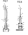
- Fig. 7 den Schnitt durch eine Biopsiekanüle nach Fig. 1, mit an dem Spritzenkolben befestigtem Mandrin;
- Fig. 8 den Schnitt durch eine Biopsiekanüle nach der Fig. 7 mit Aspirationspritze und Spritzenhalterung zur Einhandbedienung.
- 1 shows the side view of a biopsy cannula with a bevel cut with relief cut and a stylet with bevel cut in the same direction with facet cut.
- 2 shows the rear view of a biopsy cannula according to FIG. 1 with a beveled cut, relief cut and stylet;
- 3 shows the front view of a biopsy cannula according to FIG. 1 with a stylet with a longitudinal bore and facet cut;
- FIG. 4 shows the front view of a biopsy cannula according to FIG. 1 with a cannula with a bevel cut and a full stylet with an asymmetrical facet cut;
- 5 shows the top view of the cannula with relief grinding and the stylet with facet grinding according to FIG. 1;
- 6 shows the top view of the stylet with an off-center stylet tip with facet cut according to FIG. 4;
- 7 shows the section through a biopsy cannula according to FIG. 1, with the stylet attached to the syringe plunger;
- 8 shows the section through a biopsy cannula according to FIG. 7 with an aspiration syringe and syringe holder for one-hand operation.
Das in der Zeichnung dargestellte Biopsieinstrumentarium 10 besteht im wesentlichen aus einer Feinnadelbiopsie-Kanüle 11 1 mit einem längsverschiebbaren Mandrin 17. Die Kanüle 11 1 weist einen Schräganschliff 12 mit einem Facettenschliff 16 auf, der in einen Hinterschliff 13 übergeht. Dadurch entsteht im Bereich des äußeren freien Endes der Kanüle 11 eine Kanülenspitze 28 mit einer sehr scharfen, spitzen Schneidkante 45. Die Schlifflänge 15 des Schräganschliffes 12 ist etwa zwei- bis viermal, vorzugsweise dreimal so groß wie der Außendurchmesser 14 der Kanüle 11. Dadurch ergibt sich ein Anschliffwinkel 23 von ca. 20-30 o, vorzugsweise von 25 o. Der Außendurchmesser 14 der Kanüle 11 1 beträngt 0,6 bis 0,9 mm und liegt damit im Feinnadelbereich mit auf ein Minimum reduziertem Komplikationsrisiko.The
Wie in den Figuren 1 bis 5 dargestellt ist, ist die Kanüle 11 mit einem Innenlumen 22 versehen, in dem ein Mandrin 17 verschiebbar angeordnet ist. Der Mandrin 17 weist einen Mandrin-Schräganschliff 18 auf, der mit einem von der Mandrinspitze 19 ausgehenden Facettenschliff 20 versehen ist. Die Schlifflänge 15a dieses Facettenschliffes 20 ist relativ kurz und beträgt ca. 1/5 bis 1/3 der Schlifflänge 15 5 des Schräganschliffs 12.As shown in Figures 1 to 5, the
Wie die Figuren 1 und 2 zeigen, verläuft der Hinterschliff 13 der Kanüle 11 gegen den Facettenschliff 20 des Mandrins 17. Durch diese beiden Schliffe 13 und 20 entsteht eine spitze, scharfe Schneidkante 45 mit einer Längsabwinklung 25, mit der die Lederhaut leicht und richtungstreu durchstoßen werden kann. Die Schräganschliffe 12 und 18 sind dabei gleichsinnig orientiert und in ihrer Orientierung festgelegt.As FIGS. 1 and 2 show, the
Bei der in der Fig. 3 dargestellten Ausführung ist der Mandrin 17 hohl ausgebildet und mit einer Mandrin-Längsbohrung 24 versehen. Diese Längsbohrung 24 ist bei diesem Ausführungsbeispiel am Hinterende 48 des Mandrin 17 mit Querbohrungen 39 im Bereich des Spritzenkolbens 36 versehen. Durch diese Längsbohrung 24 und die Querbohrungen 39 kann das in der Aspirationsspritze 37 vorhandene Vakuum schnell an die Kanülenspitze 28 übertragen und die Probennahme unterstützt werden. Auch können dadurch Proben aus eventuell flüssigen Zielgebieten gewonnen werden, die im Ultraschall nicht oder nur sehr schwer als solche erkennbar sind. Derartige flüssigen Proben können durch die Bohrungen 24 und 39 in Richtung auf das Kanülenende 26 gesogen oder bis in den Innenraum 47 Spritze 37 gelangen.In the embodiment shown in FIG. 3, the
Der mit einem Schraganschliff 18 versehene Mandrin 17 weist im Bereich seiner Handrinspitze 19 eine Längsabwinklung 34 auf, die ein schnelles und scharfes Durchtrennen der Fpidermis erleichtert. Die Kanüle 11 ist mit einem Schräganschliff 12 mit Hinterschliff-Facetten 13 versehen und weist im Bereich der Kanülenspitze 28 eine Längsabwinklung 25 und im Bereich der Schneidkante 45 eine Schrägabwinhlungen 33 auf. Der Schräganschliff 12 ist asymmetrisch und die Kanülenspitze 28 außermittig gelegen.The
In der Fig. 4 ist eine Biopsiekanüle 11 dargestellt, bei der der Mandrin 17 ganz aus einem Vollmaterial 27 besteht. Die Mandrinspitze 31 ist dabei mit einem asymmetrischen Trokarschliff 21 versehen. Der Mandrin 17 hat, wie in der Fig. 6 in Draufsicht dagestellt ist, zwei gebogene, schrägverlaufende Schneidkanten 29 und eine gerade, senkrechtverlaufende Schneidkante 30, die in einer außermittig gelegenen Mandrinspitze 31 zusammenlaufen. Diese in Draufsicht außermittig gelegene Mandrinspitze 31 ist gleichsinnig orientiert zu der ebenfalls außermittig gelegenen Kanülenspitze 28 und in dieser Orientierung festgelegt. Die auf die asymmetrisch angeordneten Schneidkanten 29 und 30 zulaufenden Schneidenflächen 32 können konkav gewölbt sein. Durch diese Maßnahmen können auch locker aufgehängte Organe, beispielsweise Nieren und dgl., punktiert werden, ohne daß die Gefahr besteht, daß sie der Biopsiekanüle ausweichen. Fehlpunktionen können so wirksam vermieden werden.4 shows a
Wie die Fig. 7 zeigt, ist in der Kanüle 11 ein Mandrin 17 mit einem Schraganschliff 18 angeordnet, der genau in der übene das Schrägamschliffes 12 der Kanüle 11 verläuft. Der Mandrin 17 ist im Bereich des Spritzenkonus 46 in einer Mandrinführung 43 geführt und durch eine Mandrinhalterung 44 fest mit der Kolbenstange 36 der Aspirationsspritze 37 verbunden.As shown in FIG. 7, a
Die Aspirationsspritze 37 kann, wie die Fig. 8 zeigt, in eine Spritzenhalterung 38 für Einhandbedienung adaptiert sein. Diese Spritzenhalterung 38 besteht im wesentlichen aus einem Handgriff 40 zur Handhabung der Spritze 37, einer Kolbenhalterführung 42, über die der Handgriff 40 mit der Spritze 37 verbunden ist, und einem, mit dem Kolben 36 verbundenen Kolbenhalter 41, der auf der Kolbenhalterführung 42 verschiebbar ist. Eine solche Spritzenhalterung 38 ermöglicht es, die Biopsiekanüle 11 mit nur einer Hand in das Gewebe des auf dem Monitor eines Ultraschallgerätes ausgemachten Zielgebietes zu stoßen und durch Zurückziehen des 10 Kolbens 36 und damit des Mandrins 17 bei sich unmitelbar anschließendem Vorstoßen der Kanüle 11 mit der nunmehr freigegebenen Schneidkante 45 eine Gewebeprobe zu entnehmen. Dieser Eingriff ist sehr schnell und damit relativ schmerzfrei für den Patienten durchführbar.As shown in FIG. 8, the
Zum leichteren Eindringen der Kanüle 11 ist der Mandrin 17 über die Schneidkante 45 der Kanüle 11 hinaus vorgeschoben. Dadurch wird ein glatter, gewebeschonender Stichkanal erzeugt, das benachbarte Gewebe nicht zerrissen und nicht gedehnt. Die Komplikationsrate kann dadurch erheblich gesenkt werden. Die sehr feine Kanüle 11 kann dem Mandrin 17 folgen, ohne daß sich Fremdgewebe an ihr festsetzen kann. Da diese sehr feine Kanüle 11 einen Außendurchmesser von nur ca. 0,6 bis 0,9 mm aufweist, fällt sie unter Feinnadelrisiko und kann ohne große Schmerzen und Verletzungen am Patienten eingesetzt werden.The
- 10 Biopsieinstrumentarium10 biopsy instruments
- 11 Biopsiekanüle11 biopsy cannula
- 12 Schäganschliff, Kanüle12 Schäganschliff, cannula
- 13 Hinterschliff-Facette13 relief cut facet
- 14 Außendurchmesser14 outer diameter
- 15 Schliff lange15 grind long
- 15a kurze Schlifflänge15a short cut length
- 16 Facettenschliff, Kanüle16 facet cut, cannula
- 17 7 Mandrin17 7 stylet
- 18 Schräganschliff, Mandrin18 bevel cut, stylet
- 19 Mandrinspitze19 stylet tip
- 20 Facettenschliff, Mandrin20 facet cut, stylet
- 21 asymmetrischer Trokarschliff21 asymmetrical trocar cut
- 22 Innenlumen22 inner lumens
- 23 Schliffwinkel23 grinding angles
- 24 Mandrinlängsbohrung24 longitudinal stylet bore
-
25 Kanülenlangsabwinklung 26 Kanülenende25
Angled cannula 26 End of cannula - 27 Vollmaterial27 solid material
- 28 Kanülenspitze28 cannula tip
- 29 Schneidkante29 cutting edge
- 30 Schneidkante30 cutting edge
- 31 Mandrinspitze31 stylet tip
- 32 Schneidfläche32 cutting surface
- 33 Schrägabwinklung33 Oblique bend
- 34 Längsabwinklung34 Longitudinal bend
- 35 Schnittpunkt35 intersection
- 36 Kolbenstange36 piston rod
- 37 Aspirationsspritze37 Aspiration syringe
- 38 Spritzenhalterung38 syringe holder
- 39 Querbohrung39 cross hole
- 40 Handgriff40 handle
- 41 Kolbenhalter41 piston holder
- 42 Kolbenhalterführung42 Piston holder guide
- 43 Mandrinführung43 styling
- 44 Mandrinhalterung44 stylet holder
- 45 Schneidkante45 cutting edge
- 46 Spritzenkonus46 syringe cone
- 47 Innenraum47 interior
- 48 Hinterende48 rear end
Claims (8)
Applications Claiming Priority (2)
| Application Number | Priority Date | Filing Date | Title |
|---|---|---|---|
| DE3538956 | 1985-10-30 | ||
| DE3538956 | 1985-10-30 |
Publications (2)
| Publication Number | Publication Date |
|---|---|
| EP0221007A1 true EP0221007A1 (en) | 1987-05-06 |
| EP0221007B1 EP0221007B1 (en) | 1990-12-27 |
Family
ID=6285045
Family Applications (1)
| Application Number | Title | Priority Date | Filing Date |
|---|---|---|---|
| EP86730179A Expired - Lifetime EP0221007B1 (en) | 1985-10-30 | 1986-10-30 | Thin-needle biopsy cannule with a mandrel |
Country Status (4)
| Country | Link |
|---|---|
| EP (1) | EP0221007B1 (en) |
| DE (1) | DE3676630D1 (en) |
| DK (1) | DK164570C (en) |
| ES (1) | ES2019880B3 (en) |
Cited By (16)
| Publication number | Priority date | Publication date | Assignee | Title |
|---|---|---|---|---|
| EP0455626A1 (en) * | 1990-05-03 | 1991-11-06 | IMMUNO Aktiengesellschaft | Biopsy device |
| GB2256369A (en) * | 1991-06-04 | 1992-12-09 | Chiou Rei Kwen | Negative pressure biopsy needle |
| FR2705556A1 (en) * | 1993-05-28 | 1994-12-02 | Leclerc Yves | Surgical blade |
| EP0699449A4 (en) * | 1992-11-10 | 1995-08-08 | Seikagaku Kogyo Co Ltd | Injector and use of the same |
| US5615690A (en) * | 1995-02-15 | 1997-04-01 | Symbiosis Corporation | Tissue core biopsy cannula |
| WO2010054660A1 (en) * | 2008-11-11 | 2010-05-20 | Herlev Hospital | Double cannula system for anaesthetic needle |
| JP2013141488A (en) * | 2012-01-10 | 2013-07-22 | Nipro Corp | Puncture needle |
| WO2014091502A1 (en) * | 2012-12-14 | 2014-06-19 | Secretary, Department Of Biotechnology | Devices and methods for biopsy |
| EP3045118A1 (en) * | 2015-01-13 | 2016-07-20 | Covidien LP | Exchangable core biopsy needle |
| US9877708B2 (en) | 2014-07-30 | 2018-01-30 | Covidien Lp | Exchangeable core biopsy needle |
| CN107684441A (en) * | 2017-09-29 | 2018-02-13 | 黄志伟 | A kind of Raman microprobe device with fine needle aspiration biopsy's function |
| IT201700005840A1 (en) * | 2017-01-19 | 2018-07-19 | Roberto Zambelli | DEVICE FOR BIOPSY OF SOFT TISSUES AND METHOD FOR THE RECOVERY OF THE PICKED ORGANIC MATERIAL |
| US10159470B2 (en) | 2014-07-30 | 2018-12-25 | Covidien Lp | Exchangeable core biopsy needle |
| US10182798B2 (en) | 2014-07-30 | 2019-01-22 | Covidien Lp | Exchangeable core biopsy needle |
| US10363019B2 (en) | 2012-12-14 | 2019-07-30 | Secretary, Department Of Biotechnology | Biopsy needle, biopsy needle assembly, and methods for biopsy |
| WO2021090986A1 (en) * | 2019-11-08 | 2021-05-14 | 주식회사 플라워메디칼 | Biopsy needle set |
Families Citing this family (2)
| Publication number | Priority date | Publication date | Assignee | Title |
|---|---|---|---|---|
| US6142955A (en) | 1997-09-19 | 2000-11-07 | United States Surgical Corporation | Biopsy apparatus and method |
| US6712773B1 (en) | 2000-09-11 | 2004-03-30 | Tyco Healthcare Group Lp | Biopsy system |
Citations (6)
| Publication number | Priority date | Publication date | Assignee | Title |
|---|---|---|---|---|
| US3788119A (en) * | 1972-08-17 | 1974-01-29 | Baxter Laboratories Inc | Method of forming spinal needle |
| EP0019104A2 (en) * | 1979-05-19 | 1980-11-26 | Intermedicat GmbH | Biopsy needle for sampling histological specimens |
| DE3026657A1 (en) * | 1980-07-14 | 1982-02-04 | Battelle-Institut E.V., 6000 Frankfurt | Puncturing needle for sample extraction - is hollow with recess with sharp edge below conventional opening |
| US4314565A (en) | 1978-03-03 | 1982-02-09 | Lee Peter F | Biopsy and aspiration needle unit |
| EP0173653A2 (en) * | 1984-07-31 | 1986-03-05 | Roberto Zambelli | Instrument for carrying out biopsies |
| EP0186256A1 (en) * | 1984-10-24 | 1986-07-02 | Hakko Electric Machine Works Co. Ltd. | Biopsy needle set |
Family Cites Families (2)
| Publication number | Priority date | Publication date | Assignee | Title |
|---|---|---|---|---|
| DE1817555A1 (en) * | 1968-12-31 | 1971-01-07 | Baxter Laboratories Inc | Surgical instrument, especially for biopsy |
| JPS5652575A (en) * | 1979-10-05 | 1981-05-11 | Hitachi Ltd | Sealing for runner of fluid machine |
-
1986
- 1986-10-29 DK DK517386A patent/DK164570C/en not_active IP Right Cessation
- 1986-10-30 EP EP86730179A patent/EP0221007B1/en not_active Expired - Lifetime
- 1986-10-30 DE DE8686730179T patent/DE3676630D1/en not_active Expired - Lifetime
- 1986-10-30 ES ES86730179T patent/ES2019880B3/en not_active Expired - Lifetime
Patent Citations (6)
| Publication number | Priority date | Publication date | Assignee | Title |
|---|---|---|---|---|
| US3788119A (en) * | 1972-08-17 | 1974-01-29 | Baxter Laboratories Inc | Method of forming spinal needle |
| US4314565A (en) | 1978-03-03 | 1982-02-09 | Lee Peter F | Biopsy and aspiration needle unit |
| EP0019104A2 (en) * | 1979-05-19 | 1980-11-26 | Intermedicat GmbH | Biopsy needle for sampling histological specimens |
| DE3026657A1 (en) * | 1980-07-14 | 1982-02-04 | Battelle-Institut E.V., 6000 Frankfurt | Puncturing needle for sample extraction - is hollow with recess with sharp edge below conventional opening |
| EP0173653A2 (en) * | 1984-07-31 | 1986-03-05 | Roberto Zambelli | Instrument for carrying out biopsies |
| EP0186256A1 (en) * | 1984-10-24 | 1986-07-02 | Hakko Electric Machine Works Co. Ltd. | Biopsy needle set |
Cited By (23)
| Publication number | Priority date | Publication date | Assignee | Title |
|---|---|---|---|---|
| EP0455626A1 (en) * | 1990-05-03 | 1991-11-06 | IMMUNO Aktiengesellschaft | Biopsy device |
| GB2256369A (en) * | 1991-06-04 | 1992-12-09 | Chiou Rei Kwen | Negative pressure biopsy needle |
| DE4206566A1 (en) * | 1991-06-04 | 1992-12-10 | Chiou Rei Kwen | BIOPSY METHOD AND DEVICE FOR IMPLEMENTING THE METHOD |
| GB2256369B (en) * | 1991-06-04 | 1995-10-25 | Chiou Rei Kwen | Improved biopsy device |
| EP0699449A4 (en) * | 1992-11-10 | 1995-08-08 | Seikagaku Kogyo Co Ltd | Injector and use of the same |
| EP0699449A1 (en) * | 1992-11-10 | 1996-03-06 | Seikagaku Kogyo Kabushiki Kaisha | Injector and use of the same |
| US5827236A (en) * | 1992-11-10 | 1998-10-27 | Seikagaku Kogyo Kabushiki Kaisha | Injection tool and method of its use |
| FR2705556A1 (en) * | 1993-05-28 | 1994-12-02 | Leclerc Yves | Surgical blade |
| US5615690A (en) * | 1995-02-15 | 1997-04-01 | Symbiosis Corporation | Tissue core biopsy cannula |
| US5928162A (en) * | 1995-02-15 | 1999-07-27 | Symbiosis Corporation | Tissue core biopsy cannula |
| WO2010054660A1 (en) * | 2008-11-11 | 2010-05-20 | Herlev Hospital | Double cannula system for anaesthetic needle |
| JP2013141488A (en) * | 2012-01-10 | 2013-07-22 | Nipro Corp | Puncture needle |
| WO2014091502A1 (en) * | 2012-12-14 | 2014-06-19 | Secretary, Department Of Biotechnology | Devices and methods for biopsy |
| US10363019B2 (en) | 2012-12-14 | 2019-07-30 | Secretary, Department Of Biotechnology | Biopsy needle, biopsy needle assembly, and methods for biopsy |
| US9877708B2 (en) | 2014-07-30 | 2018-01-30 | Covidien Lp | Exchangeable core biopsy needle |
| US10159470B2 (en) | 2014-07-30 | 2018-12-25 | Covidien Lp | Exchangeable core biopsy needle |
| US10182798B2 (en) | 2014-07-30 | 2019-01-22 | Covidien Lp | Exchangeable core biopsy needle |
| EP3045118A1 (en) * | 2015-01-13 | 2016-07-20 | Covidien LP | Exchangable core biopsy needle |
| US9844362B2 (en) | 2015-01-13 | 2017-12-19 | Covidien Lp | Exchangeable core biopsy needle |
| US10758213B2 (en) | 2015-01-13 | 2020-09-01 | Covidien Lp | Exchangeable core biopsy needle |
| IT201700005840A1 (en) * | 2017-01-19 | 2018-07-19 | Roberto Zambelli | DEVICE FOR BIOPSY OF SOFT TISSUES AND METHOD FOR THE RECOVERY OF THE PICKED ORGANIC MATERIAL |
| CN107684441A (en) * | 2017-09-29 | 2018-02-13 | 黄志伟 | A kind of Raman microprobe device with fine needle aspiration biopsy's function |
| WO2021090986A1 (en) * | 2019-11-08 | 2021-05-14 | 주식회사 플라워메디칼 | Biopsy needle set |
Also Published As
| Publication number | Publication date |
|---|---|
| ES2019880B3 (en) | 1991-07-16 |
| DE3676630D1 (en) | 1991-02-07 |
| DK164570B (en) | 1992-07-20 |
| DK517386A (en) | 1987-05-01 |
| DK517386D0 (en) | 1986-10-29 |
| EP0221007B1 (en) | 1990-12-27 |
| DK164570C (en) | 1992-12-07 |
Similar Documents
| Publication | Publication Date | Title |
|---|---|---|
| EP0221007B1 (en) | Thin-needle biopsy cannule with a mandrel | |
| DE69633750T2 (en) | Device for automatic biopsy and soft tissue removal | |
| US5823970A (en) | Biopsy needle set | |
| DE60133297T2 (en) | BIOPSY SYSTEM | |
| DE19758808B4 (en) | Sampling device for body fluid | |
| DE3917051C2 (en) | ||
| DE69731921T2 (en) | Minimally invasive biopsy device | |
| DE3518547C2 (en) | Hollow needle of a biopsy set | |
| US5449001A (en) | Biopsy needle | |
| CA2184904C (en) | Improved cutting tip for biopsy needle | |
| DE3341117C2 (en) | Biopsy cannula | |
| DE69434842T2 (en) | Device for multiple sampling of biopsy specimens | |
| DE3508013C2 (en) | ||
| EP2957233B1 (en) | Joint biopsy needle for taking tissue samples | |
| EP0843536B1 (en) | Surgical instrument | |
| DE69628596T2 (en) | DEVICE FOR TAKING A TISSUE SAMPLE | |
| WO2001008572A1 (en) | Cannula system for introducing endoscopic tools in a human or animal body | |
| EP0243341B1 (en) | Biopsy device for sampling tissue probes and application of substances in one operation | |
| DD287651A5 (en) | BIOPSIEKANUELE | |
| DE4320008C2 (en) | Biopsy cannula | |
| DE102017104301A1 (en) | Biopsy needle guide with two-stage fixation | |
| EP0296421B1 (en) | Biopsyneedle | |
| DE60101003T2 (en) | Bone biopsy device and associated manufacturing method | |
| DE10032007A1 (en) | Ophthalmic surgical instrument with needle for taking biopsies has outer and inner housings sliding telescopically and holding cannula leading to collection vessel | |
| DE3712869C2 (en) |
Legal Events
| Date | Code | Title | Description |
|---|---|---|---|
| PUAI | Public reference made under article 153(3) epc to a published international application that has entered the european phase |
Free format text: ORIGINAL CODE: 0009012 |
|
| AK | Designated contracting states |
Kind code of ref document: A1 Designated state(s): BE DE ES FR GB NL SE |
|
| 17P | Request for examination filed |
Effective date: 19871013 |
|
| 17Q | First examination report despatched |
Effective date: 19890413 |
|
| GRAA | (expected) grant |
Free format text: ORIGINAL CODE: 0009210 |
|
| AK | Designated contracting states |
Kind code of ref document: B1 Designated state(s): BE DE ES FR GB NL SE |
|
| GBT | Gb: translation of ep patent filed (gb section 77(6)(a)/1977) | ||
| ET | Fr: translation filed | ||
| REF | Corresponds to: |
Ref document number: 3676630 Country of ref document: DE Date of ref document: 19910207 |
|
| PLBE | No opposition filed within time limit |
Free format text: ORIGINAL CODE: 0009261 |
|
| STAA | Information on the status of an ep patent application or granted ep patent |
Free format text: STATUS: NO OPPOSITION FILED WITHIN TIME LIMIT |
|
| 26N | No opposition filed | ||
| PGFP | Annual fee paid to national office [announced via postgrant information from national office to epo] |
Ref country code: GB Payment date: 19940930 Year of fee payment: 9 |
|
| PGFP | Annual fee paid to national office [announced via postgrant information from national office to epo] |
Ref country code: SE Payment date: 19941007 Year of fee payment: 9 |
|
| PGFP | Annual fee paid to national office [announced via postgrant information from national office to epo] |
Ref country code: ES Payment date: 19941014 Year of fee payment: 9 |
|
| PGFP | Annual fee paid to national office [announced via postgrant information from national office to epo] |
Ref country code: NL Payment date: 19941031 Year of fee payment: 9 |
|
| PGFP | Annual fee paid to national office [announced via postgrant information from national office to epo] |
Ref country code: BE Payment date: 19941103 Year of fee payment: 9 |
|
| EAL | Se: european patent in force in sweden |
Ref document number: 86730179.8 |
|
| PG25 | Lapsed in a contracting state [announced via postgrant information from national office to epo] |
Ref country code: GB Effective date: 19951030 |
|
| PG25 | Lapsed in a contracting state [announced via postgrant information from national office to epo] |
Ref country code: SE Effective date: 19951031 Ref country code: ES Free format text: LAPSE BECAUSE OF THE APPLICANT RENOUNCES Effective date: 19951031 Ref country code: BE Effective date: 19951031 |
|
| BERE | Be: lapsed |
Owner name: LUBBERS HEIKO Effective date: 19951031 |
|
| PG25 | Lapsed in a contracting state [announced via postgrant information from national office to epo] |
Ref country code: NL Effective date: 19960501 |
|
| GBPC | Gb: european patent ceased through non-payment of renewal fee |
Effective date: 19951030 |
|
| EUG | Se: european patent has lapsed |
Ref document number: 86730179.8 |
|
| NLV4 | Nl: lapsed or anulled due to non-payment of the annual fee |
Effective date: 19960501 |
|
| PGFP | Annual fee paid to national office [announced via postgrant information from national office to epo] |
Ref country code: FR Payment date: 19971016 Year of fee payment: 12 |
|
| PG25 | Lapsed in a contracting state [announced via postgrant information from national office to epo] |
Ref country code: FR Free format text: LAPSE BECAUSE OF NON-PAYMENT OF DUE FEES Effective date: 19990630 |
|
| REG | Reference to a national code |
Ref country code: FR Ref legal event code: ST |
|
| REG | Reference to a national code |
Ref country code: ES Ref legal event code: FD2A Effective date: 19991007 |
|
| PGFP | Annual fee paid to national office [announced via postgrant information from national office to epo] |
Ref country code: DE Payment date: 20041227 Year of fee payment: 19 |
|
| PG25 | Lapsed in a contracting state [announced via postgrant information from national office to epo] |
Ref country code: DE Free format text: LAPSE BECAUSE OF NON-PAYMENT OF DUE FEES Effective date: 20060503 |