EP0222466A2 - Apparatus and method for automatically performing analytical testing of individual fluid samples - Google Patents
Apparatus and method for automatically performing analytical testing of individual fluid samples Download PDFInfo
- Publication number
- EP0222466A2 EP0222466A2 EP86301431A EP86301431A EP0222466A2 EP 0222466 A2 EP0222466 A2 EP 0222466A2 EP 86301431 A EP86301431 A EP 86301431A EP 86301431 A EP86301431 A EP 86301431A EP 0222466 A2 EP0222466 A2 EP 0222466A2
- Authority
- EP
- European Patent Office
- Prior art keywords
- fluid
- sample
- test
- reservoir
- cell
- Prior art date
- Legal status (The legal status is an assumption and is not a legal conclusion. Google has not performed a legal analysis and makes no representation as to the accuracy of the status listed.)
- Withdrawn
Links
Images


Classifications
-
- B—PERFORMING OPERATIONS; TRANSPORTING
- B01—PHYSICAL OR CHEMICAL PROCESSES OR APPARATUS IN GENERAL
- B01L—CHEMICAL OR PHYSICAL LABORATORY APPARATUS FOR GENERAL USE
- B01L3/00—Containers or dishes for laboratory use, e.g. laboratory glassware; Droppers
- B01L3/50—Containers for the purpose of retaining a material to be analysed, e.g. test tubes
- B01L3/508—Containers for the purpose of retaining a material to be analysed, e.g. test tubes rigid containers not provided for above
-
- G—PHYSICS
- G01—MEASURING; TESTING
- G01N—INVESTIGATING OR ANALYSING MATERIALS BY DETERMINING THEIR CHEMICAL OR PHYSICAL PROPERTIES
- G01N33/00—Investigating or analysing materials by specific methods not covered by groups G01N1/00 - G01N31/00
- G01N33/48—Biological material, e.g. blood, urine; Haemocytometers
- G01N33/483—Physical analysis of biological material
- G01N33/487—Physical analysis of biological material of liquid biological material
- G01N33/49—Blood
- G01N33/4905—Determining clotting time of blood
-
- G—PHYSICS
- G01—MEASURING; TESTING
- G01N—INVESTIGATING OR ANALYSING MATERIALS BY DETERMINING THEIR CHEMICAL OR PHYSICAL PROPERTIES
- G01N35/00—Automatic analysis not limited to methods or materials provided for in any single one of groups G01N1/00 - G01N33/00; Handling materials therefor
- G01N35/00029—Automatic analysis not limited to methods or materials provided for in any single one of groups G01N1/00 - G01N33/00; Handling materials therefor provided with flat sample substrates, e.g. slides
-
- G—PHYSICS
- G01—MEASURING; TESTING
- G01N—INVESTIGATING OR ANALYSING MATERIALS BY DETERMINING THEIR CHEMICAL OR PHYSICAL PROPERTIES
- G01N35/00—Automatic analysis not limited to methods or materials provided for in any single one of groups G01N1/00 - G01N33/00; Handling materials therefor
- G01N35/02—Automatic analysis not limited to methods or materials provided for in any single one of groups G01N1/00 - G01N33/00; Handling materials therefor using a plurality of sample containers moved by a conveyor system past one or more treatment or analysis stations
- G01N35/025—Automatic analysis not limited to methods or materials provided for in any single one of groups G01N1/00 - G01N33/00; Handling materials therefor using a plurality of sample containers moved by a conveyor system past one or more treatment or analysis stations having a carousel or turntable for reaction cells or cuvettes
-
- G—PHYSICS
- G01—MEASURING; TESTING
- G01N—INVESTIGATING OR ANALYSING MATERIALS BY DETERMINING THEIR CHEMICAL OR PHYSICAL PROPERTIES
- G01N35/00—Automatic analysis not limited to methods or materials provided for in any single one of groups G01N1/00 - G01N33/00; Handling materials therefor
- G01N35/00029—Automatic analysis not limited to methods or materials provided for in any single one of groups G01N1/00 - G01N33/00; Handling materials therefor provided with flat sample substrates, e.g. slides
- G01N2035/00039—Transport arrangements specific to flat sample substrates, e.g. pusher blade
- G01N2035/00049—Transport arrangements specific to flat sample substrates, e.g. pusher blade for loading/unloading a carousel
-
- G—PHYSICS
- G01—MEASURING; TESTING
- G01N—INVESTIGATING OR ANALYSING MATERIALS BY DETERMINING THEIR CHEMICAL OR PHYSICAL PROPERTIES
- G01N35/00—Automatic analysis not limited to methods or materials provided for in any single one of groups G01N1/00 - G01N33/00; Handling materials therefor
- G01N35/00029—Automatic analysis not limited to methods or materials provided for in any single one of groups G01N1/00 - G01N33/00; Handling materials therefor provided with flat sample substrates, e.g. slides
- G01N2035/00099—Characterised by type of test elements
- G01N2035/00138—Slides
-
- G—PHYSICS
- G01—MEASURING; TESTING
- G01N—INVESTIGATING OR ANALYSING MATERIALS BY DETERMINING THEIR CHEMICAL OR PHYSICAL PROPERTIES
- G01N35/00—Automatic analysis not limited to methods or materials provided for in any single one of groups G01N1/00 - G01N33/00; Handling materials therefor
- G01N2035/00346—Heating or cooling arrangements
- G01N2035/00356—Holding samples at elevated temperature (incubation)
- G01N2035/00376—Conductive heating, e.g. heated plates
-
- G—PHYSICS
- G01—MEASURING; TESTING
- G01N—INVESTIGATING OR ANALYSING MATERIALS BY DETERMINING THEIR CHEMICAL OR PHYSICAL PROPERTIES
- G01N35/00—Automatic analysis not limited to methods or materials provided for in any single one of groups G01N1/00 - G01N33/00; Handling materials therefor
- G01N2035/00346—Heating or cooling arrangements
- G01N2035/00435—Refrigerated reagent storage
-
- G—PHYSICS
- G01—MEASURING; TESTING
- G01N—INVESTIGATING OR ANALYSING MATERIALS BY DETERMINING THEIR CHEMICAL OR PHYSICAL PROPERTIES
- G01N35/00—Automatic analysis not limited to methods or materials provided for in any single one of groups G01N1/00 - G01N33/00; Handling materials therefor
- G01N35/10—Devices for transferring samples or any liquids to, in, or from, the analysis apparatus, e.g. suction devices, injection devices
- G01N35/1009—Characterised by arrangements for controlling the aspiration or dispense of liquids
- G01N2035/1025—Fluid level sensing
Definitions
- the present invention is directed to automated analytical apparatus to detect the time of formation of fibrin clots in human or animal blood plasma by the pro- thrombin time (PT) test, the activated partial thromboplastin time (APTT) test, thrombin time test (TT) or other clotting factor tests and assays.
- PT pro- thrombin time
- APTT activated partial thromboplastin time
- TT thrombin time test
- the invention also has utility in other automated testing applications in addition to blood coagulation, including but not limited to clinical chemistry, serology and the like.
- Methods of detecting the formation of fibrin clots date back to the late 1870's. Such methods were manual. For example, in one test a white horse hair was drawn through a blood specimen. The endpoint of the clotting time was the point where shreds of fibrin could be visually detected on the hair. By 1910, an electrical apparatus called a "coaguloviscosimeter" was developed which directly measured the change in viscosity of a blood sample as it clotted. The apparatus provided a direct indication of voltage which could be plotted against clotting time.
- Clot elasticity analyzers consist of a pin, with an attached mirror, which rotates in a stainless steel cuvette which contains the plasma sample. Light is directed onto the mirror and is reflected from the mirror onto photosensitive film. As the clot develops, the elasticity of the sample changes, changing the mirror position and altering the pattern of light projected on the film. Either plasma or whole blood may be used, but whole blood testing is inferior to plasma testing because (1) extraneous factors in whole blood may affect test results, (2) test time is much longer, and (3) the test is much less specific.
- a filament moves through the sample, and the clot adheres to the filament as the clot forms.
- the clot which becomes attached to and moves with the filament, interrupts a light beam to initiate end point detection. Either plasma or whole blood may be used with this system.
- a special sensing probe is moved through a sample. As the clot forms, the probe movement is impeded. More energy is required to maintain the same degree of movement of the probe through the sample.
- the instrument displays a recording of the amount of energy required to keep the probe in motion. The amount of energy can be related to clotting time.
- Optical density detection systems operate on the principle that an increase in density of the coagulating plasma will decrease the transmission of light through the sample.
- the test sample is placed in a transparent sample cuvette and reacted with a test reagent. Light is directed through the reacted sample.
- a typical test reagent used in coagulation testing is a biological substance called thromboplastin, derived from brain tissue of rabbits. Such reagents are delicate and expensive.
- Advantages of optical systems include (1) no contact with sample, no cross-contamination, and no contact activation by agitating the specimen; (2) continuous observation of clot formation, which yields increased reproducibility of test results; (3) a consistent end point; and (4) ease of automation, thereby minimizing human error.
- Modern optical systems no longer depend on an absolute optical density change or a direct voltage reading from a photocell. Instead, modern systems operate on the first or second derivative of the photocell voltage. Thus, modern systems are independent of initial optical density or color of the sample.
- transverse line-of-sight detectors a light source and photodetector.are placed on diametrically opposite sides of the sample cuvette.
- transverse line-of-sight systems typically reauire large volumes of plasma and reagent, because it is necessary, for accurate detection, to direct the light through approximately the central third of the sample. Since relatively large amounts of expensive test reagent are required, transverse line-of-sight detectors are expensive to operate.
- a light source is located above the sample cuvette and the photodetector is located underneath the cuvette.
- the optics must compensate for the meniscus at the surface of the sample.
- the volume of sample and reagent must be controlled to extremely close tolerances, since differences in liquid depth in the cuvette could alter the test results.
- frothing of the sample may occur, resulting in a number of bubbles on and below the surface of the sample. The bubbles will lead to false readings and unreliable results.
- No existing equipment integrates plasma separation from whole blood as part of the equipment in order to perform testing on plasma only.
- plasma separation from whole blood as part of the apparatus, a separate prior and necessary centrifugation operation is eliminated. Accordingly, throughput of test samples can be increased.
- freshly-filtered plasma yields more accurate test results than plasma obtained by centrifugation.
- the present invention is directed to apparatus for automatically performing analytical testing of individual distinct samples of biological fluids wherein one or more test reagents are introduced into the samples and the reacted samples are tested for a change in optical characteristics.
- the apparatus comprises memory means for storing a plurality of different test protocols and means for selecting one of said plurality of test protocols from the memory.
- a sample cell means for receiving the individual distinct sample of biological fluid to be tested is provided.
- the apparatus has means for receiving an individual sample cell and for sensing the presence of an individual sample cell. Means are provided for heating the individual sample cell to a preselected temperature.
- the apparatus has means for transporting an individual sample cell to a first location adapted to filter unwanted nonfluid material from the fluid to be tested and to remove excess fluid to be tested from the sample cell to cause a precise, accurate volume of fluid to be tested to remain in the sample cell.
- Means are provided for transporting the individual sample cell from the first location to a second location adapted to introduce a first reagent into the sample, and means are provided for transporting the individual sample cell from the second location to a test location.
- the test location has means for introducing a second reagent to the sample and means for optically scanning the sample in a vertical direction relative to the individual sample cell, and includes means for optically detecting a change in an optical characteristic of the sample.
- the apparatus has means for providing an indication that a change in the optical characteristic of the sample has been detected.
- the invention also includes two different apparatuses for receiving a sample of fluid to be tested.
- One sample receiving apparatus has slide means having at least one cavity in its top surface for receiving and holding a quantity of fluid to be tested and body means slideably engaged with the slide means.
- the slide means is slideable between a first position relative to the body means and a second position relative to the body means.
- the bottom surface of the body means faces the top surface of the slide means.
- the body means has at least one opening through it from its top surface to its bottom surface. The opening is in alignment with the cavity in the slide means when the slide means is in the first position whereby fluid to be tested is introduced into the cavity through the opening.
- the body means also has at least one downwardly opening chamber in it, the lower end of said chamber being in the same plane as the bottom surface of the body means and being substantially closed except for an opening through the bottom surface.
- the chamber has a downwardly projecting member extending from the upper end of the chamber into the chamber.
- the chamber is in alignment with the cavity in the slide means when the slide means is in the second position to form a test cell comprising the chamber and the cavity.
- the top surface of the slide means is in sliding contact with the bottom surface of the body means to form means for removing excess fluid to be tested from the cavity as the slide means moves relative to the body means from the first position to the second position. This causes a precise, accurate volume of fluid to remain in the cavity.
- the other sample-receiving apparatus receives a sample of fluid containing non-fluid components and filters the non-fluid components from the fluid and comprises slide means having at least one cavity in its top surface for receiving and holding a quantity of filtered fluid to be tested and body means slideably engaged with the slide means.
- the slide means is slideable between a first position relative to the body means and a second position relative to the body means.
- the bottom surface of the body means faces the top surface of the slide means.
- the body means has a plurality of fluid flow channels in its top surface and at least one opening through the body means from the channels to the bottom surface. The opening communicates with the cavity in the slide means when the slide means is in the first position.
- a fluid reservoir means is located on the top surface of the body means above the fluid flow channels.
- the fluid reservoir means has two chambers, each chamber being substantially open at its top end and substantially closed at its bottom end except for an opening therethrough which communicates with the fluid flow channels.
- a filter means is located between the fluid flow channels and the openings in the bottom end of the fluid reservoir chambers for filtering the non-fluid components from the fluid.
- the body means also has at least one downwardly opening chamber therein separate from the fluid reservoir. The lower end of the chamber is in the same plane as the bottom surface of the body means and is substantially closed except for an opening therethrough.
- the chamber has a downwardly projecting member extending from the upper end of the chamber into the chamber. The chamber is in alignment with the cavity in the slide means when the slide means is in the second position to form a test cell comprising the chamber and the cavity.
- the top surface of the slide means is in sliding contact with the bottom surface of the body means to form means for removing excess fluid to be tested from the cavity as the slide means moves relative to the body means from the first position to the second position. This causes a precise accurate volume of fluid to remain in the cavity.
- the invention further includes apparatus for delivering precise volumes of a liquid.
- the apparatus has at least one liquid reservoir for containing liquid to be delivered and means for pressurizing the liquid reservoir with a gas to a preselected pressure. Means for automatically regulating the preselected pressure to maintain the pressure at a constant value are provided.
- the apparatus has nozzle means for dispensing the liquid to be delivered into a receptacle and conduit means for conducting the liquid to be delivered from the reservoir to the nozzle means.
- the conduit means are adapted to impart a constant flow rate to liquid being conducted from the reservoir to the nozzle means.
- Valve means are located in the conduit means between the reservoir and the nozzle means. Means are provided for opening the valve means for precise, predetermined time intervals whereby a precise predetermined volume of liquid flows through the valve means in the predetermined time interval.
- the invention also includes a method of delivering precise volumes of a liquid.
- the method comprises the steps of storing the liquid to be delivered in a reservoir, pressurizing the reservoir with a gas at a preselected pressure, automatically regulating the preselected pressure to maintain the pressure at a constant value and causing the liquid to be delivered to flow at a constant rate from the reservoir for precise, predetermined time intervals whereby precise, predetermined volumes of liquid flow from the reservoir in the predetermined time intervals.
- FIG. 1 an analytical apparatus 10 in accordance with the present invention.
- the apparatus has an operator keyboard 12 by which an operator may enter instructions and generally control operation of the apparatus 10. .
- keyboard 12 Associated with keyboard 12 is an alphanumeric display 14 by means of which prompts, status of the apparatus and other information may be visually displayed to an operator.
- a printing unit 16 is provided for making a printed record of test results for the tests performed on apparatus 10. Test results may also be displayed on alphanumeric display 14, or by any other visible display.
- a housing 20 contains the mechanical and pneumatic parts necessary for operation of the invention. These parts will be described in greater detail below as required.
- a removable waste bin 22 shown in phantom in Figure 1. Waste bin 22 receives samples after testing for antiseptic disposal.
- a conveyor 24 is provided for receiving sample cells 26 from the operator after a whole blood or plasma sample has been placed thereinto.
- Conveyor 24 comprises a conveyor chain 28 and guide rails 30 and 32, which define a path along which samples cells 26 are moved by conveyor chain 28.
- Conveyor chain 28 is driven by a stepping motor 62.
- first microswitch 34 which is mounted to detect passage of either a plasma or whole blood sample cell 26 along the conveyor 24 toward the indexing/filtration station 36.
- second microswitch 38 Mounted on guide rail 32 is a second microswitch 38.
- Microswitch 38 is elevated with respect to microswitch 34, and is activated only when a whole blood cell is present on the conveyor. It will be understood that any other means of detecting sample cells 26 on conveyor 24, such as by using optical detectors, may be used without departing from the invention.
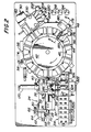
- Carousel 42 comprises a plurality of sample cell receiving stations 44 located around the circumference of carousel 42. Associated with each sample cell receiving station 44 is a resilient spring finger 46 which serves to hold the sample cell in position as carousel 42 moves the sample cell to the pre-test reagent delivery station 48 and test station 50, as required.
- Carousel 42 is driven by a stepping motor 52, as best seen in Figure 3.
- Carousel 42 is also heated by an electric resistance heater 54 which heats carousel 42, and all sample cells 26 on carousel 42, to a temperature of 37°C. This insures that all testing will be done at 37°C.
- position sensor 56 which in the preferred embodiment may be a Hall effect sensor, which detects when magnet 58 moves past sensor 56.
- position sensor 56 which in the preferred embodiment may be a Hall effect sensor, which detects when magnet 58 moves past sensor 56.
- Hall effect sensors are well understood, and need not be described here in detail.
- indexing of carousel 42 using a stepping motor and position sensor is also well known, and need not be described in detail.
- any other method of sensing and controlling angular posi- tion of carousel 42 such as using a shaft encoder and an optical sensor, may be substituted for a Hall effect sensor without departing from the scope of the invention.
- Carousel 42 rotates in the clockwise direction, as shown by the arrow in Figure 2.
- carousel 42 receives a sample cell 26 from conveyor 24, and conveys them to pre-test reagent delivery station 48, where pre-test reagents are delivered to cell 26 if required.
- Pre-test reagent delivery station 48 is located above sample cell receiving stations 44 on carousel. From there, sample cell 26 is delivered and transferred to test station 50, where actual testing of the sample is conducted.
- Test station 50 is located adjacent carousel 42. After the test is completed, sample cell 26 is removed from test station 50 and discharged into waste bin 22 via chute 60.
- conveyor 24 is driven by an electric stepping motor 62, which is coupled to the conveyor drive shaft 64 via transmission 66.
- the exact manner in which conveyor chain 28 is driven is not critical to the operation of the present invention.
- Linear position of conveyor chain 28, and therefore linear position of any sample cell 26 which may be present on conveyor 24, is determined by a second Hall effect sensor 68 which senses the passage of magnets 70 located at periodic intervals along conveyor.chain 28.
- any known type of conveyor position sensor may be used to determine linear position of conveyor chain 28.
- sample cell engaging member 72 Associated with each magnet on conveyor 23 is a sample cell engaging member 72 which engages sample cells 26 and moves them from the inlet end of conveyor 24 to indexing/filtering station 36 and then to carousel 42.
- the apparatus 10 of the present invention is designed to perform coagulation testing on blood plasma.
- Either blood plasma or whole blood may be used. If whole blood is used as the starting material apparatus 10 has the capability of extracting the plasma from the whole blood, so that a prior separation operation, such as centrifugation, need not be carried out. If blood plasma has already been separated from a whole blood sample, the separation of plasma from whole blood need not be performed by apparatus 10 and testing will proceed on the plasma sample. Regardless of whether whole blood or blood plasma is used as the starting material, all testing is performed on blood plasma.
- the present invention employs two novel sample cells, a plasma cell for use when a plasma sample has already been separated from whole blood, and a whole blood cell for use when whole blood is used as the starting material.
- the sample cell will contain duplicate plasma specimens, so that all testing is performed simultaneously in duplicate.
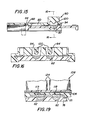
- a plasma cell is illustrated in Figures 13-16.
- the plasma cell is designated generally by reference numeral 74.
- Plasma cell 74 consists of two parts, slide portion 76 and body portion 78. Slide portion 76 is also used in the whole blood cell, to be described hereinafter.
- Plasma cell 74 as shown in Figure 13 is configured for receiving a plasma sample, whereby body portion 78 and slide portion 76 are in alignment on all four sides. In that position, openings 80 in body portion 78 are aligned with hemispherical wells 82 in slide portion 76. Wells 82 preferably have a volume of 25 microliters. Because of the small volume of wells 32, only a very small amount of plasma, and therefore only a very small amount of test reagent, is required for testing. This results in a large savinq in expensive biological test reagents. Thus, the present invention is relatively inexpensive to operate.
- a blood plasma sample is dispensed into each of wells 82 through openings 80, for example by a transfer operation.
- This operation is done manually by a laboratory technician. Alternatively, as will be recognized by those of ordinary skill in the art, the transfer operation may be done automatically, further reducing operator intervention.
- cell 74 is placed on the inlet end of conveyor 24.
- no manual operations need be performed with the apparatus of the present invention.
- Body portion 78 and slide portion 76 of plasma cell 74 are movable relative to each other.
- slide portion 76 may move to the left relative to body portion 78 without restriction.
- Slide portion 76 may also move to the right relative to body portion 78, but movement in the rightward direction is limited by stop 84 on slide portion 76, which moves in a channel 86 on body portion 78.
- Channel 86 has an end wall 88 which in cooperation with stop 84 limits movement of slide portion 76 in the rightward direction as viewed in Figure 13.
- Body portion 78 of plasma slide 74 has a raised molded portion 90.
- Raised molded portion 90 supports cavities 92, which cooperate with locating pins on the pre-testing reagent delivery station 48,and test station 50, to be described in greater detail below.
- Molded portion 90 also supports two downwardly opening cylindrical cavities 94, which are substantially open at their bottom end, i.e., the end which faces slide portion 76. Cylindrical cavities 94 are substantially closed at their opposite end, with the exception of two openings 96 and 98 respectively.
- Opening 96 is generally eliptical in shape and permits reagent to be injected into the cell 74, as will be described in greater detail below.
- Opening 98 is a vent opening, which permits air to be vented as reagent is injected. Opening 98 may be eliminated for ease of molding body portion 78. Opening 96 is sufficient for proper venting.
- Projections 100 Projecting downwardly from the substantially closed end of cylindrical cavities 94 are substantially cylindrical projections 100. Projections 100, also referred to herein as “liqht pipes" 100, are important to the optical inspection of the test sample, to be described in greater detail below.
- Slide portion 76 and body portion 78 of cell 74 are preferably constructed of a clear polystyrene material or an equivalent. Slide portion 76 and body portion 78 of cell 74 are substantially transparent.
- Cavities 92 and 94 of molded portion 90 are connected together by molding ribs 102, which facilitate fa h rication of body portion 78.
- 1-7hole blood cell 104 which is used when whole blood is used as the starting material, is illustrated in Figures 17-19.
- Whole blood cell 104 comprises slide portion 76, body portion 106 and reservoir portion 108.
- Slide portion 76 is identical to slide portion 76 of plasma cell 74.
- Body portion 106 comprises a molded portion 90', which contains structure substantially identical to that in molded portion 90 of body portion 78 of plasma cell 74.
- molded portion 90' contains cavities 92' which cooperate with locating pins at the pretest reagent dispensing station 48 and test station 50.
- Molded portion 90' also includes two cylindrical cavities 94', each of which have a reagent inlet opening 96' and vent opening 98', all substantially as described in connection with the corresponding elements in the plasma cell body portion 78. Projecting downwardly from the substantially closed cylindrical cavities 94' are light pipes 100'. Molding ribs 102' connect cavities 92' and 94'.
- body portion 106 has a plasma collection area 110.
- Plasma collection area 110 comprises a number of longitudinal channels 112 interconnected by and which communicate with a transverse channel 114. Channels 112 and 114 collect filtered plasma from whole blood placed in reservoir portion 108, as will be described in Section III below.
- An.opening 116 is provided in channel 114 through which collected plasma may flow into wells 82 in slide portion 76.
- plasma channel 118 On the underside of body portion 106 beneath the plasma collection area 110, and communicating with opening 116, is plasma channel 118. Plasma channel 118 allows collected plasma from channels 112 and 114 which has flowed through opening 116 to flow into sample wells 82 on slide portion 76.
- Body portion 106 Located in channel 118 is a bubble trap 120 to prevent any bubbles in the collected plasma from being carried into sample wells 82.
- Body portion 106 also includes cylindrical cavities 119, which act as secondary bubble traps to prevent any trapped air in the collected plasma from reducing the sample volume delivered to sample cells 82, and which also act as excess material traps. Excess material is sheared off when slide portion 76 is indexed from the first postion to the second position.
- Reservoir portion 108 of whole blood cell 104 is located in recess 122 in body portion 106 (see Figure 19) and comprises twin reservoirs 124 which overlie and align with plasma collection area 112 of body portion 106.
- Reservoirs 124 are substantially rectangular in shape and are open at the top. The bottom ends of reservoirs 124 are substantially closed except for generally rectangular openings 126. The bottom ends of reservoirs 124 are slightly raised with respect to the side walls of reservoirs 124 so as to form a channel 127 (see Figure 18) below reservoirs 124.
- a filter membrane 128 Located below reservoirs 124 and between reservoir portion 108 and plasma collection area 110 of body portion 106 is a filter membrane 128.
- Reservoirs 124 are in communication via openings 126 and channel 127 formed below reservoirs 124 and above filter membrane 128.
- the filter membrane 128 may be a polycarbonate sheet having a plurality of pores, pore density being approximately 3 x 10 7 pores per square centimeter and maximum pore size being approximately 0.6 micron. Filter membrane 128 separates plasma from the whole blood placed in one of reservoirs 124, as will be described in greater detail in Section III.
- Indexing/filtering station 36 performs two major functions: (1) when whole blood is used as the starting material, the indexing/filtering station 36 causes the blood plasma to be extracted from the whole blood and (2) indexes slide portion 76 of either a plasma cell or a whole blood cell to provide a precise plasma sample volume for testing. A description and operation of the indexing/filtering station 36 in relation to the extraction of plasma from whole blood will be described first.
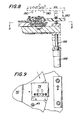
- a whole blood cell 104 is shown in position at the indexing/filtering station 36.
- Whole hlood cell 104 is transported to position at indexing/ filtering station 36 by conveyor 24.
- Indexing/filtering station 36 comprises a movable head portion 130.
- Head portion 130 is reciprocally movable in a vertical direction by a pneumatic cylinder 132.
- Pneumatic cylinder 132 is a double-acting cylinder.
- Cylinder 132 has a piston (not visible) to which is attached a piston shaft 134.
- the free end of piston shaft 134 is fastened to bracket 136, which is fixed to conveyor 24.
- a bracket 137 is attached to cylinder 132 and is movable therewith. Fastened to bracket 137 are posts 138 (only one post is visible in Figures 5 and 6). Cylinder 132 moves up and down in concert with head portion 130, while piston shaft 134 remains fixed to bracket 136.
- Head portion 130 is mounted on the ends of posts 138 furthest from bracket 137. Head portion 130 comprises a body portion 140 and a cover portion 142. Cover portion 142 is removably attached to body portion 140 by fasteners 144. Fasteners 144 May, for example, be thumb screws or the like.
- Within body portion 140 are two chambers, a left chamber 146 and a right chamber 148 (see Figure 2). Only right chamber 148 is illustrated in Figures 5 and 6. Chambers 146 and 148 are preferably cylindrical, but may have any other shape as well. Each chamber has an increased diameter portion 150 at its top. The increased diameter portion is adapted to seat an O-ring 152 so as to form a tight seal between cover portion 142 and the chamber.
- a filtering material 154 may be located in the chambers to prevent whole blood from entering air passageways 156.
- Passageways 156 form air inlets into chambers 146 and 148. Air is supplied to and removed from chambers 146 and 148 by means of passageways 156 and tubing 158. Chambers 146 and 148 have air passages 160 in their bottom surfaces.
- Seal 162 has an opening 164 through which air.from chamber 148 may pass into reservoir portion 108 of whole blood cell 104. Seal 162 is substantially impermeable to air, so that air flows only through openinq 164. Seal 162 is resilient so as to form a tight seal between body portion 140 and reservoir 108 of whole blood cell 104.
- head portion 130 When a whole blood cell 104 is first moved into position at indexing/filtering station 36, head portion 130 is at its upper position, shown in phantom in Figure 6. After whole blood cell 104 is in place, head portion 130 is moved downwardly by pneumatic cylinder 132 until seal 162 rests on top of reservoir portion 108 of whole blood cell 104.
- Whole blood cell 104 is positioned such that left chamber 146 is located above one reservoir 124 and right chamber 148 is located above the other reservoir. Air at a nominal pressure of 3 psi is alternately admitted into and bled from left chamber 146 and right chamber 148 via tubing 158. That is, left chamber 146 and right chamber 148 are alternately pressurized and vented, respectively.
- a light source 168 which may be a light emitting diode or other light source, is located on one side of whole blood cell 104. On the opposite side of whole blood cell 104 is located a photodetector 166. A separate light source 16F and photodetector 166 are provided for each reservoir 124. Light source 168 and photodetector 166 are aligned so that the optical line-of-sight is through the lower portion of reservoirs 124.
- pneumatic cylinder 170 is activated, which causes an associated piston shaft 172 to move to the left as viewed in Figures 5 and 6.
- a bracket 174 which is aligned opposite slide portion 76 of whole blood cell 104.
- slide portion 76 is moved to the left relative to body portion 106 until stop 84 contacts end wall 88' of channel 86' in hody portion 106 of whole blood cell 104.
- piston shaft 172 moves to the right so that bracket 174 clears whole blood cell 104.
- head 130 is moved to is uppermost position by cylinder 132.
- a plasma cell 74 containing the plasma sample is placed on conveyor 24. Conveyor 24 moves plasma cell 74 into position at indexing/filtering station 36. Since the sample is plasma, no filtering operation need be done. Thus, once plasma cell 74 is in position at indexing/filtering station 36, only pneumatic cylinder 170 is activated, which moves slide portion 76 relative to body portion 78 until stop 84 contacts end wall 88 of channel 86 in body portion 78. When indexing is complete, piston shaft 172 moves to the right so that bracket 174 clears plasma cell 74. Simultaneously, head 130 is moved to its uppermost position by cylinder 132.
- plasma cell 74 is shown in what may be termed the indexed position. In this position, cylindrical cavities 94 are located over and coaxial with plasma well 82. Cylindrical cavities 94 and plasma wells 82 cooperate to form test chambers. Movement of slide portion 76 relative to body portion 78 not only brings cavities 94 into alignment with plasma wells 82 to form test chambers, but any excess plasma introduced into the plasma cell is sheared off by the lower surface of body portion 78. This results in very precisely controlled volumes of plasma remaining in plasma wells 82. This eliminates the need for precise volumetric dispensing of the plasma sample, and eliminates the possibility of having a sample size which is larger than necessary and which may yield inaccurate test results.
- the plasma cell 74 is now ready to be placed onto carousel 42 by conveyor 24 for further processing.
- carousel stepping motor 52 advances carousel 42 to move a vacant sample cell receiving station 44 opposite the outlet end of conveyor 24.
- the conveyor stepping motor 62 is directed toladvance to its starting position. This action causes a sample cell at the indexing/filtering station 36 to advance onto the sample cell receiving station 44 on carousel 42.
- the sample cell and the sample in contains are allowed to equilibrate to 37°C, at which temperature all further processing is carried out.
- the plasma cell 74 is now ready to be moved to pre- test reagent delivery station 48 if required.
- plasma cell 74 is moved by carousel 42 to p re-test reagent delivery station 48.
- Pre-test reagent delivery station 48 is shown in Figures 7 and 8.
- Pre-test reagent delivery station comprises two solenoid valves 176 and 178 for controlling delivery of reagent into the test chamber on plasma cell 74. Solenoid valves 176 and 178 are mounted on a olate 180. For clarity, solenoid valves 176 and 178 are omitted from Figure 8. However, it is believed that the operation of pre-test reagent delivery station 48 can be understood completely by reference to Figures 7 and 8.
- Plate 180 is vertically reciprocable by means of posts 182 which are fastened to bracket 184 connected to the piston 186 of a pneumatic cylinder 188.
- plate 180 As a plasma cell 74 is moved into position at pre- test reagent dispensing station 48, plate 180 is at its highest position. This allows plasma cell 74 to be easily moved into place. Once plasma cell 74 is in place, plate 180 is moved downwardly by piston 186 and cylinder 188. A downwardly projecting carousel locating pin 189 on plate 180 enters the carousel locating hole 45 ( Figure 9) adjacent the sample cell receiving station 44 in which plasma cell 74 is situated. As plate 180 continues its downward motion, downwardly projecting sample cell locating pins 190 enter locating cavities 92 in plasma cell 74 so that cell 74 is precisely aligned with respect to the pre-test reagent delivery station 48.
- nozzles 192 enter reagent inlet openings 96 in plasma cell 74.
- Nozzles 192 deliver reagent from reagent bottle 194 (see Figure 2).
- Flow of pre-test reagent from reagent bottle 194 is controlled by solenoid valves 176 and 178.
- the reagent delivery system is described in greater detail in Section VI.D. below. Although delivery of only one reagent is described, it will be apparent that provision for delivery of any number of pre-test reagents may be made without departing from the invention.
- the cell After the proper amount of pre-test reagent is delivered into the test chambers in plasma cell 74, the cell is allowed to incubate for a preselected time until actual testing is to be performed.
- the incubated sample When the incubated sample is ready for testing, it is moved by carousel 42 to test station 50 and transferred to test station 50 by pneumatic cylinder 312 and pawl 313.
- Pawl 313 is advanced to position a (shown in phantom in Figure 3). Movement of pawl 313 is limited by pin 315, which is operated by pneumatic cylinder 314, so that plasma cell 74 is located in proper position at test station 50. After plasma cell 74 is in position, nawl 313 is retracted by cylinder 312 to its initial position.
- Test station 50 is shown in Figures 10 through 12. Test station 50 is maintained at 37°C by a separate heater (not shown). Test station 50 comprises a head portion 196 which is movable vertically by means of a pneumatic cylinder 198 and piston arrangement substantially identical to that described for the indexing/filtering station and the pre- test reagent delivery station. Head portion 196 comprises a plate 200 on which are mounted solenoid valves 202, 204, 206 and 208. Each solenoid valve has associated with it a nozzle 210, 212, 214 and 216, respectively. Nozzles 210 and 216 dispense a first test reagent from reagent bottle 218 (see Figure 2).
- Nozzles 212 and 214 deliver a different reagent from reagent bottle 220 (see Figure 2).
- Reagent bottles 194, 218 and 220 are maintained at 2 to 8°C by a thermoelectric cold module (not shown).
- the particular reagent required is determined in accordance with the particular test to be performed on the plasma sample. Although provision for delivery of two reagents is described, those skilled in the art will recognize that provision can be made for delivery of any number of reagents without departing from the scope of the present invention.
- Nozzles 210, 212, 214 and 216 are connected to solenoid valves 202, 204, 206 and 208 via flexible tubing 222, 224, 226, and 228 and thermally conductive tubing 223, 225, 227 and 229, respectively.
- a heater (not shown) in head 230 is in thermal contact with tubing 223, 225, 227 and 229 in order to maintain a dosage of reagent at 37°C, so that introduction of the reagent into the plasma sample will not change the temperature of the plasma sample.
- the length of flexible tubing 222, 224, 226 and 228 and thermally conductive tubing 223, 225, 227 and 229 is chosen such that the liquid volume in the thermally conductive tubing between the valve and the nozzle orifice is equal to the desired volume of liquid to be delivered for a particular test.
- optical inspection head 230 Located above nozzles 210, 212, 214 and 216 and their associated tubing is optical inspection head 230.
- Optical inspection head includes a pair of light sources 232 located above and to the inside of nozzles 210 and 212, and nozzles 214 and 216. See Figure 12.
- Located below and in axial alignment with light sources 232 are a pair of photodetectors 234 to detect light transmitted through the plasma sample. Photodetectors 234 are mounted in a plate 236 which is fixed in the plane of carousel 42.
- the axes of light sources 232 and photodetectors 234 are located so as to coincide with the axes of light pipes 100 in plasma cell 74 when placed in position by pawl 313. Thus, optical detection of clotting time is observed by passing light through the test sample via light pipes 100 in a vertical direction.
- optical inspection head 230 is moved downwardly by pneumatic cylinder 198. Downwardly projecting locating pins 231 on head 230 enter locating cavities 92 in plasma cell 74 so that cell 74 is precisely aligned with respect to test station 50. That is, cell 74 is positioned so that the axes of liqht sources 232 and photodetectors 234 are precisely aligned with the axes of light pipes 100. At the same time, nozzles 210, 212, 214 and 216 enter openings 96 on plasma cell 74.
- test reagent When the head 230 is in its lowest position, a sufficient amount of test reagent is injected by nozzles 210 and 216 or nozzles 212 and 214, as required, in order to raise the level of the sample in the test chambers in plasma cell 74 so that light pipes 100 become immersed in the sample liquid.
- light from light sources 232 enters the sample from liqht pipes 100, eliminating an air/liquid interface. This eliminates any potential problems due to reflection of the light from the surface of the sample, and also eliminates any problems due to bubbles on the surface of the sample which may have been caused by introduction of the sample or introduction of the reaqents into the test chamber.
- the cylindrical shape and rounded end of light pipes 100 serves to disperse the light from light sources 232 through a full 360° in the test chambers. Thus, the entire sample in the test chambers is illuminated and observation of the entire sample can be made. This yields highly accurate and precise test results, results which are not obtained by known optical inspection systems.
- head 230 is moved to its uppermost position by cylinder 198.
- Plasma cell 74 is ready to be ejected.
- carousel 42 moves the next sample cell into position opposite test station 50, and the next sample cell is moved onto test station 50 by pawl 313. Movement of the next sample cell onto test station 50 ejects the previous sample cell from test station 50 onto chute 60, from where the previous sample cell falls into waste bin 22.
- pin 315 is retracted by cylinder 314, (see Figure 3) and pawl 313 is advanced by cylinder 312 to position b (shown in phantom in Fiqure 3). Pawl 313 thus ejects the sample cell from test station 50 onto chute 60 for disposal.
- the reagents used for testing are biological reagents.
- a spring-loaded reaqent receptacle is provided to collect denatured reagent discharged from test station 50 when a sample cell is not present.
- the spring-loaded receptacle is hiased to a position under nozzles 210, 212, 214 and 216 when a cell is not on test station 50. The receptacle is pushed aside out of the way when a sample cell is put onto test station 50.
- the overall analyzer control system is shown in block diagram form in Figure 21.
- the heart of the analyzer control system is microprocessor 238 which controls operation of the analyzer.
- the microprocessor receives siqnals from the operator keyboard 12; cell detec- tion electronics 240; filter system electronics 242; motion control electronics 244; temperature control electronics 246; reagent delivery electronics 248; and clot detection electronics 250.
- microprocessor 238 drives alphanumeric display 14 and printer 16, and controls operation of the various subsystems mentioned.
- Cell detection electronics 240 consist of microswitches 34 and 38 (see Figure 2).
- Microswitch 34 detects the presence of any cell on conveyor 24.
- Microswitch 38 detects whether the cell on conveyor 24 is a plasma cell or a whole blood cell. As noted above, microswitch 38 is elevated with respect to microswitch 34, and is high enough to clear a plasma cell, so that when a plasma cell is placed on conveyor 24, microswitch 38 is not activated. Microswitch 38 is activated only when a whole blood cell is placed on conveyor 24. Microswitch 38 is activated when the reservoirs 124 of a whole blood cell move past microswitch 38.
- the temperature control electronics employ suitable temperature sensors at the test station, test head, and carousel, as well as at a separate cold module (not shown) -which is used to cool the reagent bottles 194, 218 and 220. Any suitable conventional temperature control techniques may be used.
- the motion control system 244 is shown in greater detail in Figure 22.
- the Hall effect sensors 56 and 68 for the carousel and conveyor, respectively, generate inputs to the microprocessor 238.
- the microprocessor drives the carousel stepping motor and conveyor stepping motor 52 and 62, respectively, through suitable drive electronics.
- the way in which a stepper motor may be driven is well known, and need not be described in detail here.
- Microprocessor 238 also controls the operation of solenoid valves, collectively designated by reference numeral 316 ( Figure 22) by means of the solenoid valve driver electronics. Solenoid valves 316 control operation of the pneumatic cylinders associated with the various subsystems, such as the indexing/filtering station, pre- test reagent delivery station and test station.
- the pneumatic system is shown in greater detail in Figures 20A and 20B, and is described in greater detail in Section VI.G. in connection with those figures.
- the filtration control system is shown in Figure 23.
- signals from the photodetectors 166 which detect whole blood level in reservoirs 124 have their outputs connected to suitable level detector electronics 252.
- suitable level detector electronics 252 Conventional level detection techniques may be employed.
- the output from the level detector electronics is sent to microprocessor 238.
- microprocessor 238 drives solenoid valves 254 and 256 by means of solenoid driver circuits 258.
- Solenoid valves 254 and 256 are three-way valves.
- microprocessor 238 switches solenoid valve 254 from pressure to exhaust and switches solenoid valve 256 from exhaust to pressure.
- reservoir 1 ceases to be pressurized and is vented through solenoid valve 254, while reservoir 2 becomes pressurized via valve 256.
- This causes the whole blood to cease flowing from reservoir 1 to reservoir 2, and reverses the flow of whole blood so that the flow is now from reservoir 2 to reservoir 1.
- microprocessor 238 switches solenoid valve 256 from pressure to exhaust and switches solenoid valve 254 from exhaust to pressure. Now, blood no longer flows from reservoir 2 to reservoir 1, but flows in the initial direction. The process is repeated for a number of cycles sufficient to collect the required plasma sample.
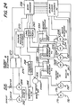
- the reagent delivery system is shown in block diagram form in Figure 24.
- the level of reagent in reagent bottles 194, 218 and 220 is monitored by electrode level sensors 330, 332 and 334, which are connected to level sensor electronics 260.
- Level sensor electronics 260 monitor a small current passed through each of the electrodes 330, 332 and 334 to determine whether the bottom of each electrode is immersed in liquid. The manner in which this is accomr- lished is well known to those skilled in the art.
- the output of level sensor electronics 260 is sent to microprocessor 238. In the event the level of any reagent in any of the reservoirs falls below a predetermined minimum, microprocessor 238 will signal the operator and, if appropriate, prevent further testinq from being attempted until the low reagent is replenished.
- reagent bottles 194, 218 and 220 are pressurized to approximately 4 pounds per square inch.
- Solenoid valves 262 and 264 act as a pressure regulator to regulate the 20 psi used to operate the pneumatic cylinders which move the indexing/filtering station, pre-test reagent dispensing station and test station, down to 4 psi.
- a 4 psi reservoir 266 holds a sufficient quantity of air to pressurize reagent bottles 194, 218 and 220.
- a pressure transducer 268 and pressure regulator electronics 270 regulate the operation of solenoid valve 264 through solenoid driver 274. Any suitable pressure transducer 268, pressure regulator electronics 270 and solenoid driver electronics 274 can be used.
- Solenoid valve 262 is operated by microprocessor 238 through solenoid driver electronics 272.
- a precise 4 psi pressure is present in reservoir 266 at the time reagent is dispensed. This is achieved in the following manner. Exhaust valve 262 is opened to exhaust air from reservoir 266 by solenoid driver electronics 272 on command from microprocessor 238. Microprocessor 238 simultaneously monitors the state of pressure regulator electronics 270 to determine when the falling pressure in reservoir 266 will cause pressure regulator electronics 270 to open solenoid valve 264 via solenoid driver elec- tronices 274. When this occurs, microprocessor 238 closes exhaust valve 262 via solenoid drive electronics 272. Microprocessor 238 continues to monitor pressure regulator electronics 270 until it receives indication that solenoid valve 264 has been closed. When this occurs, pressure in reservoir 266 stands precisely at its nominal 4 psi value, and any one or any pair of the dispense valves 176, 178, 202, 204, 206 and 208 can be operated.
- Precise metering of reagents dispensed from reagent bottles 194, 218 and 220. is obtained by carefully controlling the time during which any of the solenoid valves 176, 17R, 202, 204, 206 or 208 is held open. Because the reagent bottles are pressurized to a precise pressure, reaoent will flow through a dispensing nozzle at a precise fixed rate. This rate can be determined for the nozzle diameter bv well known formulae. Since the reagent flows at a fixed, known rate, a known amount can be delivered by controlling the time during which the reagent flows. Thus, rather than attempt to monitor and meter reagent flow by sensing the amount of flow, reagent metering is controlled by time of flow.
- the clot detection circuitry is diagrammed in Figure 25. To the left of Figure 25, a simplified sketch of the test chamber in a sample cell 74 is shown. As noted above, the liquid level of the test sample 276 is high enough so that light pipe 100 is immersed in sample 276. Light from light source 232 is conducted downwardly through light pipe 100 and from there through sample 276 and sample well 82 to photodetector 234. Light source 232 is preferably a near-infrared LED light source and is driven by microprocessor 238 by means of LED driver 278. Light source 232 is not energized continuously. Rather, light source 232 is pulsed, as by waveform T LED shown in the timing diagram in Figure 25. Thus, light source 232 is alternately on and off during the test cycle.
- sample 276 The light transmitted through sample 276 is detected by photodector 234, which, in known manner, generates an electrical signal proportional to the amount of light detected.
- the signal is preamplified in preamplifier 280 and sent to two sample and hold circuits 282 and 284.
- Sample and hold circuit 282 is gated to sample the "base line", or voltage level when the light source is turned off. Refer to waveform T 1 in Figure 25.
- Sample and hold circuit 284 is gated to sample the light detected by photodetector 234 when light source 232 is on. Refer to waveform To in Figure 25.
- the outputs of sample and hold circuits 282 and 284 are sent to difference amplifier 286.
- the output of difference amplifier 286 is thus substantially the difference between light levels detected by photodetector 234 when light source 232 is energized and when it is off. Since the time interval between pulses T 1 and To is on the order of 40 usec, it will be seen that the clot detection electronics are thus independent of ambient lighting, since only the difference between the light emitted by light source 232 and the ambient light level is used. There will be essentially no change in ambient lighting over a 40 usec period. Moreover, a 40 usec period renders the detection electronics insensitive to 50 Hz or 60 Hz flicker, which is always present in ambient lighting.
- the output of difference amplifier 286 is differentiated in differentiator circuit 288 and further amplified. By differentiating the signal, the rate of change of optical transmissivity of the plasma sample is detected. By using the rate of change instead of an absolute change in transmissivity, coagulation end point can be measured independent of initial color variations or density variations within the plasma sample.
- the amplified differentiated signal is sent to input multiplexer 290.
- the undifferentiated output of the difference amplifier 286 is also sent to input multiplexer 290. Thus, either the undifferentiated or differentiated difference signal is available to microprocessor 238.
- the selected output of input multiplexer 290 is converted to digital form in analog-to-digital converter 292 and is sent to the microprocessor 238, which further processes the signal and calculates coagulation end point.
- Microprocessor sample selection logic is illustrated by the flow chart in Figure 26. Each time a test is to be selected the microprocessor determines whether or not any test samples which may have.been aborted for any reason are on the carousel. If so, the aborted test sample is ejected from the carousel. Checking for aborted test samples continues until no more aborted test samples remain on the carousel. When no more aborted test samples remain on the carousel, the microprocessor then determines whether - or not any APTT tests are incubating on the carousel and are within a predetermined time of completeing their incubation period.
- the microprocessor determines whether or not any PT test samples are on the carousel and have been there for more than the predetermined warm-up time, T W . If so, the PT test sample is offloaded onto the test station and the test is started. If not, the microprocessor then looks to determine whether or not any APTT test cells currently incubating have been incubating for less than a predetermined maximum APTT test time, APTT MAX . If the answer is no, microprocessor determines whether any APTT test not yet incubating has been on the carousel for more than the minimum warm-up time, Tw.
- APTT reagent is injected into the non- incubating APTT cell which has been on the carousel the longest to start incubation, and the microprocessor returns to the start sequence. If the answer to the previous questins is yes, the microprocessor looks to see whether or not there is an empty station on the carousel. If there is an empty station on the carousel, and a test sample is ready to be loaded into the carousel, the new test cell is loaded in the first available carousel station and the start sequence is initiated. If there are no empty stations on the carousel, the microprocessor waits two seconds and then initiates the start sequence. The same is true if no test has been requested.
- tests may be performed in the most efficient order, not necessarily the order in which sample cells are loaded onto the conveyor. Thus, tests may be carried out in any order irrespective of the order in which test samples are put into the apparatus.
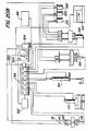
- the pneumatic system is illustrated in simplified terms in Figures 20A and 20B.
- An air compressor 294 driven by the ac power to the apparatus charges a 20 psi reservoir 296 via a check valve 300. Pressure in reservoir 296 is controlled by a pressure switch 298. Air at 20 psi is supplied to the solenoid valves 316 which control the operation of various system components (as described in connection with Figure 22) via line 320. Solenoid valves 316 are opened or closed by microprocessor 238 as required to operate the various air cylinders. Air cylinder 132 moves the index/filtering station head 130 up and down. Cylinder 170 indexes the sample cell.
- Cylinder 312 moves a sample cell from the carousel to the test station and ejects samples to be discarded.
- Cylinder 188 operates the pre-test reagent plate 180.
- Cylinder 198 operates the test head 196.
- Cylinder 314 operates the test station stop pin 315, which limits movement of pawl 313 operated by cylinder 312 so that a test cell placed at the test station is ejected only at the end of testing.
- the remaining elements in Figures 20A and 20B are numbered to correspond to the parts in individual subsystem block diagrams Figures 21-25.
- the air supply of 20 psi is reduced to approximately 3 psi by pressure regulator 322.
- Pressure regulator 322 feeds solenoid controlled valves 324 and 326, which supply 3 psi air to indexing/filtering station 36. That is, solenoid valves 324 and 326 supply air to chambers 146 and 148 of indexing/filtering head 130 to move the whole blood back and forth between reservoirs 124 for filtering.
- Air at 20 psi is also supplied to solenoid valve 323 which supplies air to cylinder 314.
Abstract
Description
- The present invention is directed to automated analytical apparatus to detect the time of formation of fibrin clots in human or animal blood plasma by the pro- thrombin time (PT) test, the activated partial thromboplastin time (APTT) test, thrombin time test (TT) or other clotting factor tests and assays. The invention also has utility in other automated testing applications in addition to blood coagulation, including but not limited to clinical chemistry, serology and the like.
- Methods of detecting the formation of fibrin clots date back to the late 1870's. Such methods were manual. For example, in one test a white horse hair was drawn through a blood specimen. The endpoint of the clotting time was the point where shreds of fibrin could be visually detected on the hair. By 1910, an electrical apparatus called a "coaguloviscosimeter" was developed which directly measured the change in viscosity of a blood sample as it clotted. The apparatus provided a direct indication of voltage which could be plotted against clotting time.
- In the early 1920's, rudimentary photoelectric techniques were developed to detect variations in light transmissivity of a blood sample during clotting. An apparatus termed a "nephelometer" was devised which consisted of a light source that furnished constant illumination to the sample. During coagulation of the sample, variations in the optical transmissivity of the sample were registered by a thermopile connected to a sensitive galvanometer. By reading the movements of the galvanometer needle, transmissivity values could be plotted against elapsed time.
- In the mid 1930's, investigations of the coagulation of blood plasma using more sophisticated photoelectric techniques were conducted. It was noted that an increase in density occurs as blood coagulates. The possibility of detecting this change by photoelectric techniques was investigated. This led to the development of an instrument which displayed increasing density of the sample as a gradual change in the voltage displayed by a galvanometer. In addition, a water bath was used to maintain the blood sample at 37°C.
- Early photoelectric systems were limited to one specimen at a time, and there was no way to compensate for differences in plasma density and color variations from specimen to specimen. There was also no common reference point.
- Today, five automated clotting time measurement techniques are in use: (1) electromechanical; (2) clot elasticity; (3) fibrin adhesion; (4) impedance; and (5) optical density. The principal electromechanical method in use today involves the use of a "fibrin switch" in which the physical formation of fibrin strands in a reaction mixture serves to complete an electrical circuit between two electrodes, thus stopping a timer. There are a number of limitations to "fibrin switch" systems. Clot formation cannot continually be observed. They are prone to cross-contamination and mechanical failure. An operator must clean the electrodes, exposing the operator to the risk of infection.
- Clot elasticity analyzers consist of a pin, with an attached mirror, which rotates in a stainless steel cuvette which contains the plasma sample. Light is directed onto the mirror and is reflected from the mirror onto photosensitive film. As the clot develops, the elasticity of the sample changes, changing the mirror position and altering the pattern of light projected on the film. Either plasma or whole blood may be used, but whole blood testing is inferior to plasma testing because (1) extraneous factors in whole blood may affect test results, (2) test time is much longer, and (3) the test is much less specific.
- In fibrin adhesion systems, a filament moves through the sample, and the clot adheres to the filament as the clot forms. The clot, which becomes attached to and moves with the filament, interrupts a light beam to initiate end point detection. Either plasma or whole blood may be used with this system.
- In impedance detection systems, a special sensing probe is moved through a sample. As the clot forms, the probe movement is impeded. More energy is required to maintain the same degree of movement of the probe through the sample. The instrument displays a recording of the amount of energy required to keep the probe in motion. The amount of energy can be related to clotting time.
- Optical density detection systems operate on the principle that an increase in density of the coagulating plasma will decrease the transmission of light through the sample. The test sample is placed in a transparent sample cuvette and reacted with a test reagent. Light is directed through the reacted sample. A typical test reagent used in coagulation testing is a biological substance called thromboplastin, derived from brain tissue of rabbits. Such reagents are delicate and expensive. Advantages of optical systems include (1) no contact with sample, no cross-contamination, and no contact activation by agitating the specimen; (2) continuous observation of clot formation, which yields increased reproducibility of test results; (3) a consistent end point; and (4) ease of automation, thereby minimizing human error.
- Modern optical systems no longer depend on an absolute optical density change or a direct voltage reading from a photocell. Instead, modern systems operate on the first or second derivative of the photocell voltage. Thus, modern systems are independent of initial optical density or color of the sample.
- Most optical detection systems in use today utilize lines of sight transverse to the sample cuvette. A few use lines of sight axial to the sample cuvette. In transverse line-of-sight detectors, a light source and photodetector.are placed on diametrically opposite sides of the sample cuvette. Such transverse line-of-sight systems typically reauire large volumes of plasma and reagent, because it is necessary, for accurate detection, to direct the light through approximately the central third of the sample. Since relatively large amounts of expensive test reagent are required, transverse line-of-sight detectors are expensive to operate.
- In axial .line-of-sight systems, a light source is located above the sample cuvette and the photodetector is located underneath the cuvette. with axial line-of-sight systems, the optics must compensate for the meniscus at the surface of the sample. Also, the volume of sample and reagent must be controlled to extremely close tolerances, since differences in liquid depth in the cuvette could alter the test results. Moreover, when the sample and the reagents are added to the cuvette, frothing of the sample may occur, resulting in a number of bubbles on and below the surface of the sample. The bubbles will lead to false readings and unreliable results.
- No existing equipment integrates plasma separation from whole blood as part of the equipment in order to perform testing on plasma only.
- It is an object of the present invention to provide an automated analytical apparatus to detect the time of formation of fibrin clots in human or animal blood plasma.
- It is also an object of the invention to integrate plasma separation from whole blood as part of the automated analytical apparatus in order to perform testing on plasma only. By integrating plasma separation from whole blood as part of the apparatus, a separate prior and necessary centrifugation operation is eliminated. Accordingly, throughput of test samples can be increased. In addition, freshly-filtered plasma yields more accurate test results than plasma obtained by centrifugation.
- It is also an object of the invention to provide an analytical apparatus which is "user friendly" and eliminates manual operations.
- It is also an object of the invention to provide a disposable sample cell for receiving samples of fluid to be tested. Making the sample cell disposable reduces the possible risk of infection from blood samples.
- The present invention is directed to apparatus for automatically performing analytical testing of individual distinct samples of biological fluids wherein one or more test reagents are introduced into the samples and the reacted samples are tested for a change in optical characteristics. The apparatus comprises memory means for storing a plurality of different test protocols and means for selecting one of said plurality of test protocols from the memory. A sample cell means for receiving the individual distinct sample of biological fluid to be tested is provided. The apparatus has means for receiving an individual sample cell and for sensing the presence of an individual sample cell. Means are provided for heating the individual sample cell to a preselected temperature. The apparatus has means for transporting an individual sample cell to a first location adapted to filter unwanted nonfluid material from the fluid to be tested and to remove excess fluid to be tested from the sample cell to cause a precise, accurate volume of fluid to be tested to remain in the sample cell. Means are provided for transporting the individual sample cell from the first location to a second location adapted to introduce a first reagent into the sample, and means are provided for transporting the individual sample cell from the second location to a test location. The test location has means for introducing a second reagent to the sample and means for optically scanning the sample in a vertical direction relative to the individual sample cell, and includes means for optically detecting a change in an optical characteristic of the sample. The apparatus has means for providing an indication that a change in the optical characteristic of the sample has been detected.
- The invention also includes two different apparatuses for receiving a sample of fluid to be tested. One sample receiving apparatus has slide means having at least one cavity in its top surface for receiving and holding a quantity of fluid to be tested and body means slideably engaged with the slide means. The slide means is slideable between a first position relative to the body means and a second position relative to the body means. The bottom surface of the body means faces the top surface of the slide means. The body means has at least one opening through it from its top surface to its bottom surface. The opening is in alignment with the cavity in the slide means when the slide means is in the first position whereby fluid to be tested is introduced into the cavity through the opening. The body means also has at least one downwardly opening chamber in it, the lower end of said chamber being in the same plane as the bottom surface of the body means and being substantially closed except for an opening through the bottom surface. The chamber has a downwardly projecting member extending from the upper end of the chamber into the chamber. The chamber is in alignment with the cavity in the slide means when the slide means is in the second position to form a test cell comprising the chamber and the cavity. The top surface of the slide means is in sliding contact with the bottom surface of the body means to form means for removing excess fluid to be tested from the cavity as the slide means moves relative to the body means from the first position to the second position. This causes a precise, accurate volume of fluid to remain in the cavity.
- The other sample-receiving apparatus receives a sample of fluid containing non-fluid components and filters the non-fluid components from the fluid and comprises slide means having at least one cavity in its top surface for receiving and holding a quantity of filtered fluid to be tested and body means slideably engaged with the slide means. The slide means is slideable between a first position relative to the body means and a second position relative to the body means. The bottom surface of the body means faces the top surface of the slide means. The body means has a plurality of fluid flow channels in its top surface and at least one opening through the body means from the channels to the bottom surface. The opening communicates with the cavity in the slide means when the slide means is in the first position. A fluid reservoir means is located on the top surface of the body means above the fluid flow channels. The fluid reservoir means has two chambers, each chamber being substantially open at its top end and substantially closed at its bottom end except for an opening therethrough which communicates with the fluid flow channels. A filter means is located between the fluid flow channels and the openings in the bottom end of the fluid reservoir chambers for filtering the non-fluid components from the fluid. The body means also has at least one downwardly opening chamber therein separate from the fluid reservoir. The lower end of the chamber is in the same plane as the bottom surface of the body means and is substantially closed except for an opening therethrough. The chamber has a downwardly projecting member extending from the upper end of the chamber into the chamber. The chamber is in alignment with the cavity in the slide means when the slide means is in the second position to form a test cell comprising the chamber and the cavity. The top surface of the slide means is in sliding contact with the bottom surface of the body means to form means for removing excess fluid to be tested from the cavity as the slide means moves relative to the body means from the first position to the second position. This causes a precise accurate volume of fluid to remain in the cavity. t
- The invention further includes apparatus for delivering precise volumes of a liquid. The apparatus has at least one liquid reservoir for containing liquid to be delivered and means for pressurizing the liquid reservoir with a gas to a preselected pressure. Means for automatically regulating the preselected pressure to maintain the pressure at a constant value are provided. The apparatus has nozzle means for dispensing the liquid to be delivered into a receptacle and conduit means for conducting the liquid to be delivered from the reservoir to the nozzle means. The conduit means are adapted to impart a constant flow rate to liquid being conducted from the reservoir to the nozzle means. Valve means are located in the conduit means between the reservoir and the nozzle means. Means are provided for opening the valve means for precise, predetermined time intervals whereby a precise predetermined volume of liquid flows through the valve means in the predetermined time interval.
- The invention also includes a method of delivering precise volumes of a liquid. The method comprises the steps of storing the liquid to be delivered in a reservoir, pressurizing the reservoir with a gas at a preselected pressure, automatically regulating the preselected pressure to maintain the pressure at a constant value and causing the liquid to be delivered to flow at a constant rate from the reservoir for precise, predetermined time intervals whereby precise, predetermined volumes of liquid flow from the reservoir in the predetermined time intervals.
- For the purpose of illustrating the invention, there is shown in the drawings a form which is presently preferred; it being understood, however, that this invention is not limited to the precise arrangements and instrumen- talities shown.
- Figure 1 generally illustrates the apparatus of the present invention.
-
Fiaure 2 is a top plan view of the major operational components of the invention. - Figure 3 is a bottom plan view of the components shown in Figure 2.
- Figure 4 is a detailed top plan view of the cell conveyor and the indexing/filtration station.
- Figure 5 is a section of the indexing/filtration station taken along the lines 5-5 in Figure 4 in the filtration position prior to indexing of a sample cell.
- Figure 6 is a section of the indexing/filtration station taken along the lines 5-5 in Figure 4, and showing indexing of a sample cell.
- Figure 7 is a side elevation view of the pre-test reagent delivery station.
- Figure 8 is a sectional view of the pre-test reagent delivery station taken along the lines 8-8 in Figure 2.
- Figure 9 is a top plan view of a sample cell at the pre-test reagent delivery station taken along the lines 9-9 in Figure 8.
- Figure 10 is a top plan view of the test station.
- Figure 11 is a partial sectional view of the sample test station showing test reagent dispensing nozzles taken along the line 11-11 in Figure 10.
- Figure 12 is a side elevational view of the test station taken along the lines 12-12 in Figure 10.
- Figure 13 is a top plan view of a plasma cell before aliquoting.
- Figure 14 is a sectional view of the plasma cell taken along the lines 14-14 in Figure 13.
- Figure 15 is a sectional view of a plasma cell after aliquoting.
- Figure 16 is a sectional view of the plasma cell after aliquoting taken along the lines 16-16 in Figure 15.
- Figure 17 is a top plan view and partial section view of a whole blood cell before aliquoting.
- Fiqure 13 is a sectional view of the whole blood cell taken along the lines 18-18 in Figure 17.
- Figure 19 is a sectional view of the whole blood cell taken along the lines 19-19 in Figure 18.
- Figures 20A and 20B are simplified diagrams of the pneumatic system.
- Fiqure 21 is a block diagram of the overall control system for the apparatus of the present invention.
- Figure,22 is a block diagram of the motion control system for the apparatus of the present invention.
- Fiqure 23 is a block diagram of the filtration control system for the apparatus of the present invention.
- Figure 24 is a block diagram of the reagent control system for the apparatus of the present invention.
- Figure 25 is a block diagram of the clot detection system for the apparatus of the present invention.
- Figure 26 is a flow chart showing decision criteria by which the next sample to be tested is selected by the microprocessor in the apparatus of the present invention.
- Referring now to the drawings, wherein like numerals indicate like elements, there is shown in Figure 1 an
analytical apparatus 10 in accordance with the present invention. The apparatus has anoperator keyboard 12 by which an operator may enter instructions and generally control operation of theapparatus 10.. Associated withkeyboard 12 is analphanumeric display 14 by means of which prompts, status of the apparatus and other information may be visually displayed to an operator. Aprinting unit 16 is provided for making a printed record of test results for the tests performed onapparatus 10. Test results may also be displayed onalphanumeric display 14, or by any other visible display. - Below the
operator keyboard 12 andprinting unit 16 is located the sample cell handling andtesting area 18. The sample cell handling and testing components of the invention will be described in greater detail below. Ahousing 20 contains the mechanical and pneumatic parts necessary for operation of the invention. These parts will be described in greater detail below as required. At one side ofhousing 20 is located aremovable waste bin 22, shown in phantom in Figure 1.Waste bin 22 receives samples after testing for antiseptic disposal. - Referring now to Figure 2, the major components of
analyzer 10 are shown in detail. Aconveyor 24 is provided for receivingsample cells 26 from the operator after a whole blood or plasma sample has been placed thereinto.Conveyor 24 comprises aconveyor chain 28 andguide rails samples cells 26 are moved byconveyor chain 28.Conveyor chain 28 is driven by a steppingmotor 62. - Mounted on
guide rail 30 is afirst microswitch 34 which is mounted to detect passage of either a plasma or wholeblood sample cell 26 along theconveyor 24 toward the indexing/filtration station 36. Mounted onguide rail 32 is asecond microswitch 38.Microswitch 38 is elevated with respect tomicroswitch 34, and is activated only when a whole blood cell is present on the conveyor. It will be understood that any other means of detectingsample cells 26 onconveyor 24, such as by using optical detectors, may be used without departing from the invention. - At the end of
conveyor 24 is located acarousel 42.Carousel 42 comprises a plurality of samplecell receiving stations 44 located around the circumference ofcarousel 42. Associated with each samplecell receiving station 44 is aresilient spring finger 46 which serves to hold the sample cell in position ascarousel 42 moves the sample cell to the pre-testreagent delivery station 48 andtest station 50, as required.Carousel 42 is driven by a steppingmotor 52, as best seen in Figure 3.Carousel 42 is also heated by anelectric resistance heater 54 which heatscarousel 42, and allsample cells 26 oncarousel 42, to a temperature of 37°C. This insures that all testing will be done at 37°C. - Referring again to Figure 2, angular position of
carousel 42 is detected byposition sensor 56, which in the preferred embodiment may be a Hall effect sensor, which detects whenmagnet 58 moves pastsensor 56. The operation of Hall effect sensors is well understood, and need not be described here in detail. Likewise, indexing ofcarousel 42 using a stepping motor and position sensor is also well known, and need not be described in detail. Of course, those skilled in the art will recognize that any other method of sensing and controlling angular posi- tion ofcarousel 42, such as using a shaft encoder and an optical sensor, may be substituted for a Hall effect sensor without departing from the scope of the invention. -
Carousel 42 rotates in the clockwise direction, as shown by the arrow in Figure 2. Thus,carousel 42 receives asample cell 26 fromconveyor 24, and conveys them to pre-testreagent delivery station 48, where pre-test reagents are delivered tocell 26 if required. Pre-testreagent delivery station 48 is located above samplecell receiving stations 44 on carousel. From there,sample cell 26 is delivered and transferred to teststation 50, where actual testing of the sample is conducted.Test station 50 is locatedadjacent carousel 42. After the test is completed,sample cell 26 is removed fromtest station 50 and discharged intowaste bin 22 viachute 60. - As best seen in Figure 2,
conveyor 24 is driven by anelectric stepping motor 62, which is coupled to theconveyor drive shaft 64 viatransmission 66. The exact manner in whichconveyor chain 28 is driven is not critical to the operation of the present invention. Linear position ofconveyor chain 28, and therefore linear position of anysample cell 26 which may be present onconveyor 24, is determined by a secondHall effect sensor 68 which senses the passage ofmagnets 70 located at periodic intervals alongconveyor.chain 28. As withcarousel 42, any known type of conveyor position sensor may be used to determine linear position ofconveyor chain 28. - Associated with each magnet on conveyor 23 is a sample
cell engaging member 72 which engagessample cells 26 and moves them from the inlet end ofconveyor 24 to indexing/filtering station 36 and then tocarousel 42. - The
apparatus 10 of the present invention is designed to perform coagulation testing on blood plasma. Either blood plasma or whole blood may be used. If whole blood is used as the startingmaterial apparatus 10 has the capability of extracting the plasma from the whole blood, so that a prior separation operation, such as centrifugation, need not be carried out. If blood plasma has already been separated from a whole blood sample, the separation of plasma from whole blood need not be performed byapparatus 10 and testing will proceed on the plasma sample. Regardless of whether whole blood or blood plasma is used as the starting material, all testing is performed on blood plasma. - The present invention employs two novel sample cells, a plasma cell for use when a plasma sample has already been separated from whole blood, and a whole blood cell for use when whole blood is used as the starting material. In both cases, the sample cell will contain duplicate plasma specimens, so that all testing is performed simultaneously in duplicate.
- A plasma cell is illustrated in Figures 13-16. The plasma cell is designated generally by
reference numeral 74.Plasma cell 74 consists of two parts,slide portion 76 andbody portion 78.Slide portion 76 is also used in the whole blood cell, to be described hereinafter. -
Plasma cell 74 as shown in Figure 13 is configured for receiving a plasma sample, wherebybody portion 78 andslide portion 76 are in alignment on all four sides. In that position,openings 80 inbody portion 78 are aligned withhemispherical wells 82 inslide portion 76.Wells 82 preferably have a volume of 25 microliters. Because of the small volume ofwells 32, only a very small amount of plasma, and therefore only a very small amount of test reagent, is required for testing. This results in a large savinq in expensive biological test reagents. Thus, the present invention is relatively inexpensive to operate. - A blood plasma sample is dispensed into each of
wells 82 throughopenings 80, for example by a transfer operation. This operation is done manually by a laboratory technician. Alternatively, as will be recognized by those of ordinary skill in the art, the transfer operation may be done automatically, further reducing operator intervention. After a plasma sample has been dispensed intoplasma cell 74,cell 74 is placed on the inlet end ofconveyor 24. Other than placinq thesample cell 26 with the sample onconveyor 24 and entering the appropriate instructions viakeyboard 12, no manual operations need be performed with the apparatus of the present invention. -
Body portion 78 andslide portion 76 ofplasma cell 74 are movable relative to each other. When viewed as in Figure 13,slide portion 76 may move to the left relative tobody portion 78 without restriction.Slide portion 76 may also move to the right relative tobody portion 78, but movement in the rightward direction is limited bystop 84 onslide portion 76, which moves in achannel 86 onbody portion 78.Channel 86 has anend wall 88 which in cooperation withstop 84 limits movement ofslide portion 76 in the rightward direction as viewed in Figure 13. -
Body portion 78 ofplasma slide 74 has a raised moldedportion 90. Raised moldedportion 90supports cavities 92, which cooperate with locating pins on the pre-testingreagent delivery station 48,andtest station 50, to be described in greater detail below. Moldedportion 90 also supports two downwardly openingcylindrical cavities 94, which are substantially open at their bottom end, i.e., the end which facesslide portion 76.Cylindrical cavities 94 are substantially closed at their opposite end, with the exception of twoopenings Opening 96 is generally eliptical in shape and permits reagent to be injected into thecell 74, as will be described in greater detail below.Opening 98 is a vent opening, which permits air to be vented as reagent is injected.Opening 98 may be eliminated for ease ofmolding body portion 78.Opening 96 is sufficient for proper venting. - Projecting downwardly from the substantially closed end of
cylindrical cavities 94 are substantiallycylindrical projections 100.Projections 100, also referred to herein as "liqht pipes" 100, are important to the optical inspection of the test sample, to be described in greater detail below. -
Slide portion 76 andbody portion 78 ofcell 74 are preferably constructed of a clear polystyrene material or an equivalent.Slide portion 76 andbody portion 78 ofcell 74 are substantially transparent. -
Cavities portion 90 are connected together by moldingribs 102, which facilitate fahrication ofbody portion 78. - 1-
7hole blood cell 104, which is used when whole blood is used as the starting material, is illustrated in Figures 17-19.Whole blood cell 104 comprisesslide portion 76,body portion 106 andreservoir portion 108.Slide portion 76 is identical to slideportion 76 ofplasma cell 74.Body portion 106 comprises a molded portion 90', which contains structure substantially identical to that in moldedportion 90 ofbody portion 78 ofplasma cell 74. Thus, molded portion 90' contains cavities 92' which cooperate with locating pins at the pretestreagent dispensing station 48 andtest station 50. Molded portion 90' also includes two cylindrical cavities 94', each of which have a reagent inlet opening 96' and vent opening 98', all substantially as described in connection with the corresponding elements in the plasmacell body portion 78. Projecting downwardly from the substantially closed cylindrical cavities 94' are light pipes 100'. Molding ribs 102' connect cavities 92' and 94'. - In addition to molded portion 90',
body portion 106 has a plasma collection area 110. Plasma collection area 110 comprises a number oflongitudinal channels 112 interconnected by and which communicate with atransverse channel 114.Channels reservoir portion 108, as will be described in Section III below.An.opening 116 is provided inchannel 114 through which collected plasma may flow intowells 82 inslide portion 76. On the underside ofbody portion 106 beneath the plasma collection area 110, and communicating withopening 116, is plasma channel 118. Plasma channel 118 allows collected plasma fromchannels opening 116 to flow intosample wells 82 onslide portion 76. Located in channel 118 is abubble trap 120 to prevent any bubbles in the collected plasma from being carried intosample wells 82.Body portion 106 also includescylindrical cavities 119, which act as secondary bubble traps to prevent any trapped air in the collected plasma from reducing the sample volume delivered to samplecells 82, and which also act as excess material traps. Excess material is sheared off whenslide portion 76 is indexed from the first postion to the second position. -
Reservoir portion 108 ofwhole blood cell 104 is located inrecess 122 in body portion 106 (see Figure 19) and comprisestwin reservoirs 124 which overlie and align withplasma collection area 112 ofbody portion 106.Reservoirs 124 are substantially rectangular in shape and are open at the top. The bottom ends ofreservoirs 124 are substantially closed except for generallyrectangular openings 126. The bottom ends ofreservoirs 124 are slightly raised with respect to the side walls ofreservoirs 124 so as to form a channel 127 (see Figure 18) belowreservoirs 124. Located belowreservoirs 124 and betweenreservoir portion 108 and plasma collection area 110 ofbody portion 106 is afilter membrane 128.Reservoirs 124 are in communication viaopenings 126 andchannel 127 formed belowreservoirs 124 and abovefilter membrane 128. Thefilter membrane 128 may be a polycarbonate sheet having a plurality of pores, pore density being approximately 3 x 10⁷ pores per square centimeter and maximum pore size being approximately 0.6 micron.Filter membrane 128 separates plasma from the whole blood placed in one ofreservoirs 124, as will be described in greater detail in Section III. - Indexing/
filtering station 36 performs two major functions: (1) when whole blood is used as the starting material, the indexing/filtering station 36 causes the blood plasma to be extracted from the whole blood and (2) indexes slideportion 76 of either a plasma cell or a whole blood cell to provide a precise plasma sample volume for testing. A description and operation of the indexing/filtering station 36 in relation to the extraction of plasma from whole blood will be described first. - As shown in Figures 4-6, a
whole blood cell 104 is shown in position at the indexing/filtering station 36. Wholehlood cell 104 is transported to position at indexing/filtering station 36 byconveyor 24. Indexing/filtering station 36 comprises amovable head portion 130.Head portion 130 is reciprocally movable in a vertical direction by apneumatic cylinder 132.Pneumatic cylinder 132 is a double-acting cylinder.Cylinder 132 has a piston (not visible) to which is attached apiston shaft 134. The free end ofpiston shaft 134 is fastened tobracket 136, which is fixed toconveyor 24. Abracket 137 is attached tocylinder 132 and is movable therewith. Fastened tobracket 137 are posts 138 (only one post is visible in Figures 5 and 6).Cylinder 132 moves up and down in concert withhead portion 130, whilepiston shaft 134 remains fixed tobracket 136. -
Head portion 130 is mounted on the ends ofposts 138 furthest frombracket 137.Head portion 130 comprises abody portion 140 and acover portion 142.Cover portion 142 is removably attached tobody portion 140 byfasteners 144.Fasteners 144 May, for example, be thumb screws or the like. Withinbody portion 140 are two chambers, aleft chamber 146 and a right chamber 148 (see Figure 2). Onlyright chamber 148 is illustrated in Figures 5 and 6.Chambers diameter portion 150 at its top. The increased diameter portion is adapted to seat an O-ring 152 so as to form a tight seal betweencover portion 142 and the chamber. Afiltering material 154 may be located in the chambers to prevent whole blood from enteringair passageways 156.Passageways 156 form air inlets intochambers chambers passageways 156 andtubing 158.Chambers air passages 160 in their bottom surfaces. - Below
body portion 140, and attached thereto, is aresilient seal 162.Seal 162 has an opening 164 through which air.fromchamber 148 may pass intoreservoir portion 108 ofwhole blood cell 104.Seal 162 is substantially impermeable to air, so that air flows only through openinq 164.Seal 162 is resilient so as to form a tight seal betweenbody portion 140 andreservoir 108 ofwhole blood cell 104. - When a
whole blood cell 104 is first moved into position at indexing/filtering station 36,head portion 130 is at its upper position, shown in phantom in Figure 6. Afterwhole blood cell 104 is in place,head portion 130 is moved downwardly bypneumatic cylinder 132 untilseal 162 rests on top ofreservoir portion 108 ofwhole blood cell 104.Whole blood cell 104 is positioned such thatleft chamber 146 is located above onereservoir 124 andright chamber 148 is located above the other reservoir. Air at a nominal pressure of 3 psi is alternately admitted into and bled fromleft chamber 146 andright chamber 148 viatubing 158. That is, leftchamber 146 andright chamber 148 are alternately pressurized and vented, respectively. This causes whole blood to be moved from onereservoir 124 to theother reservoir 124 throughopenings 126 at the bottoms of the reservoirs and throughchannel 127past filter membrane 128 inreservoir portion 108 ofwhole blood cell 104. As the whole blood is moved back and forth from one reservoir to the otherpast filter membrane 128, plasma is filtered from the whole blood thorughfilter membrane 128 and collected inchannels opening 116 to slideportion 76, where it is ultimately collected incavities 119 andplasma wells 82 inslide portion 76. Any excess plasma is vented throughpassageway 121 formed betweenslide portion 76 andbody portion 106. - In order to prevent air bubbles from being trapped in the filtered plasma, some portion of the whole blood is retained in each
reservoir 124 at all times, so that during cycling of the whole blood from one reservoir to the other, neither reservoir is permitted to run dry. The decreasing blood level in each reservoir is detected optically. Alight source 168, which may be a light emitting diode or other light source, is located on one side ofwhole blood cell 104. On the opposite side ofwhole blood cell 104 is located aphotodetector 166. A separate light source 16F andphotodetector 166 are provided for eachreservoir 124.Light source 168 andphotodetector 166 are aligned so that the optical line-of-sight is through the lower portion ofreservoirs 124. When the whole blood level in a reservoir drops below the line-of-sight oflight source 168 andphotodetector 166, light fromlight source 168strikes photodetector 166, and causesphotodetector 166 to generate an output signal. The output signal is detected by level detector electronics. Occurrence of the signal stops the flow of air intochamber reservoir 124, and there is no possibility of introducing air bubbles into the plasma through filter membrane l28. - After filtering of the whole blood is complete,
pneumatic cylinder 170 is activated, which causes an associatedpiston shaft 172 to move to the left as viewed in Figures 5 and 6. At the free end ofpiston shaft 172 is located abracket 174 which is alignedopposite slide portion 76 ofwhole blood cell 104. Thus, asshaft 172 andbracket 174 move to the left,slide portion 76 is moved to the left relative tobody portion 106 untilstop 84 contacts end wall 88' of channel 86' inhody portion 106 ofwhole blood cell 104. When indexing is complete,piston shaft 172 moves to the right so thatbracket 174 clearswhole blood cell 104. Simultaneously,head 130 is moved to is uppermost position bycylinder 132. - In the event that plasma is used as the starting material rather than whole blood, a
plasma cell 74 containing the plasma sample is placed onconveyor 24.Conveyor 24 movesplasma cell 74 into position at indexing/filtering station 36. Since the sample is plasma, no filtering operation need be done. Thus, onceplasma cell 74 is in position at indexing/filtering station 36, onlypneumatic cylinder 170 is activated, which movesslide portion 76 relative tobody portion 78 untilstop 84 contacts endwall 88 ofchannel 86 inbody portion 78. When indexing is complete,piston shaft 172 moves to the right so thatbracket 174 clearsplasma cell 74. Simultaneously,head 130 is moved to its uppermost position bycylinder 132. - At this point, operation of the system is the same regardless of whether a whole blood or plasma was used as the starting sample. Accordingly, further description will be directed to operation with a
plasma cell 74. - Referring now to Figures 15 and 16,
plasma cell 74 is shown in what may be termed the indexed position. In this position,cylindrical cavities 94 are located over and coaxial withplasma well 82.Cylindrical cavities 94 andplasma wells 82 cooperate to form test chambers. Movement ofslide portion 76 relative tobody portion 78 not only bringscavities 94 into alignment withplasma wells 82 to form test chambers, but any excess plasma introduced into the plasma cell is sheared off by the lower surface ofbody portion 78. This results in very precisely controlled volumes of plasma remaining inplasma wells 82. This eliminates the need for precise volumetric dispensing of the plasma sample, and eliminates the possibility of having a sample size which is larger than necessary and which may yield inaccurate test results. - It will be seen that, by virtue of the novel con- fiquration of
plasma cell 74 andwhole blood cell 104, two individual test chambers are formed by the twoplasma wells 82 inslide portion 76 and the twocylindrical cavities 94 or 94' in plasmacell body portion 78 or whole bloodcell body portion 106, respectively. This permits testing of plasma samples to be done in duplicate. By performing the tests in duplicate, a greater degree of accuracy and control is achieved. The duplicate test results can also be averaged, which smoothes out inevitiable variations in test results which occur when performing biological testing. - After indexing, the
plasma cell 74 is now ready to be placed ontocarousel 42 byconveyor 24 for further processing. Whencarousel 42 is ready to receive a sample cell,carousel stepping motor 52advances carousel 42 to move a vacant samplecell receiving station 44 opposite the outlet end ofconveyor 24. Then, theconveyor stepping motor 62 is directed toladvance to its starting position. This action causes a sample cell at the indexing/filtering station 36 to advance onto the samplecell receiving station 44 oncarousel 42. Once oncarousel 42 the sample cell and the sample in contains are allowed to equilibrate to 37°C, at which temperature all further processing is carried out. - The
plasma cell 74 is now ready to be moved to pre- testreagent delivery station 48 if required. - If the test to be performed on the plasma sample requires introducing a pre-test reagent into the plasma,
plasma cell 74 is moved bycarousel 42 to pre-testreagent delivery station 48. - Pre-test
reagent delivery station 48 is shown in Figures 7 and 8. Pre-test reagent delivery station comprises twosolenoid valves plasma cell 74.Solenoid valves olate 180. For clarity,solenoid valves reagent delivery station 48 can be understood completely by reference to Figures 7 and 8. -
Plate 180 is vertically reciprocable by means ofposts 182 which are fastened tobracket 184 connected to the piston 186 of apneumatic cylinder 188. - As a
plasma cell 74 is moved into position at pre- testreagent dispensing station 48,plate 180 is at its highest position. This allowsplasma cell 74 to be easily moved into place. Onceplasma cell 74 is in place,plate 180 is moved downwardly by piston 186 andcylinder 188. A downwardly projectingcarousel locating pin 189 onplate 180 enters the carousel locating hole 45 (Figure 9) adjacent the samplecell receiving station 44 in whichplasma cell 74 is situated. Asplate 180 continues its downward motion, downwardly projecting samplecell locating pins 190enter locating cavities 92 inplasma cell 74 so thatcell 74 is precisely aligned with respect to the pre-testreagent delivery station 48. Also, downwardly projectingnozzles 192 enterreagent inlet openings 96 inplasma cell 74.Nozzles 192 deliver reagent from reagent bottle 194 (see Figure 2). Flow of pre-test reagent fromreagent bottle 194 is controlled bysolenoid valves - After the proper amount of pre-test reagent is delivered into the test chambers in
plasma cell 74, the cell is allowed to incubate for a preselected time until actual testing is to be performed. When the incubated sample is ready for testing, it is moved bycarousel 42 to teststation 50 and transferred to teststation 50 bypneumatic cylinder 312 andpawl 313.Pawl 313 is advanced to position a (shown in phantom in Figure 3). Movement ofpawl 313 is limited bypin 315, which is operated bypneumatic cylinder 314, so thatplasma cell 74 is located in proper position attest station 50. Afterplasma cell 74 is in position,nawl 313 is retracted bycylinder 312 to its initial position. -
Test station 50 is shown in Figures 10 through 12.Test station 50 is maintained at 37°C by a separate heater (not shown).Test station 50 comprises ahead portion 196 which is movable vertically by means of apneumatic cylinder 198 and piston arrangement substantially identical to that described for the indexing/filtering station and the pre- test reagent delivery station.Head portion 196 comprises aplate 200 on which are mountedsolenoid valves nozzle Nozzles Nozzles Reagent bottles reagent bottles -
Nozzles valves flexible tubing conductive tubing head 230 is in thermal contact withtubing - The length of
flexible tubing conductive tubing - Located above
nozzles optical inspection head 230. Optical inspection head includes a pair oflight sources 232 located above and to the inside ofnozzles nozzles light sources 232 are a pair ofphotodetectors 234 to detect light transmitted through the plasma sample.Photodetectors 234 are mounted in aplate 236 which is fixed in the plane ofcarousel 42. - The axes of
light sources 232 andphotodetectors 234 are located so as to coincide with the axes oflight pipes 100 inplasma cell 74 when placed in position bypawl 313. Thus, optical detection of clotting time is observed by passing light through the test sample vialight pipes 100 in a vertical direction. - After
plasma cell 74 is placed in position attest station 50,optical inspection head 230 is moved downwardly bypneumatic cylinder 198. Downwardly projecting locatingpins 231 onhead 230enter locating cavities 92 inplasma cell 74 so thatcell 74 is precisely aligned with respect to teststation 50. That is,cell 74 is positioned so that the axes ofliqht sources 232 andphotodetectors 234 are precisely aligned with the axes oflight pipes 100. At the same time,nozzles enter openings 96 onplasma cell 74. - When the
head 230 is in its lowest position, a sufficient amount of test reagent is injected bynozzles nozzles plasma cell 74 so thatlight pipes 100 become immersed in the sample liquid. Thus, light fromlight sources 232 enters the sample fromliqht pipes 100, eliminating an air/liquid interface. This eliminates any potential problems due to reflection of the light from the surface of the sample, and also eliminates any problems due to bubbles on the surface of the sample which may have been caused by introduction of the sample or introduction of the reaqents into the test chamber. - The cylindrical shape and rounded end of
light pipes 100 serves to disperse the light fromlight sources 232 through a full 360° in the test chambers. Thus, the entire sample in the test chambers is illuminated and observation of the entire sample can be made. This yields highly accurate and precise test results, results which are not obtained by known optical inspection systems. - At this point, optical inspection is performed as described in detail in Section VI.E. below.
- After optical inspection is completed,
head 230 is moved to its uppermost position bycylinder 198.Plasma cell 74 is ready to be ejected. If another test is to be run,carousel 42 moves the next sample cell into position oppositetest station 50, and the next sample cell is moved ontotest station 50 bypawl 313. Movement of the next sample cell ontotest station 50 ejects the previous sample cell fromtest station 50 ontochute 60, from where the previous sample cell falls intowaste bin 22. If no further tests are to be run,pin 315 is retracted bycylinder 314, (see Figure 3) andpawl 313 is advanced bycylinder 312 to position b (shown in phantom in Fiqure 3).Pawl 313 thus ejects the sample cell fromtest station 50 ontochute 60 for disposal. - Typically, the reagents used for testing are biological reagents. Thus, such reagents will denature after a finite time at 37°C and will no longer be fresh. It is therefore advantageous to discard reagents which have been at 37°C for too long a time. For this purpose, a spring-loaded reaqent receptacle, not shown, is provided to collect denatured reagent discharged from
test station 50 when a sample cell is not present. The spring-loaded receptacle is hiased to a position undernozzles test station 50. The receptacle is pushed aside out of the way when a sample cell is put ontotest station 50. - The overall analyzer control system is shown in block diagram form in Figure 21. The heart of the analyzer control system is
microprocessor 238 which controls operation of the analyzer. As inputs, the microprocessor receives siqnals from theoperator keyboard 12; cell detec-tion electronics 240;filter system electronics 242;motion control electronics 244;temperature control electronics 246;reagent delivery electronics 248; andclot detection electronics 250. As outputs,microprocessor 238 drivesalphanumeric display 14 andprinter 16, and controls operation of the various subsystems mentioned. -
Cell detection electronics 240 consist ofmicroswitches 34 and 38 (see Figure 2).Microswitch 34 detects the presence of any cell onconveyor 24.Microswitch 38 detects whether the cell onconveyor 24 is a plasma cell or a whole blood cell. As noted above,microswitch 38 is elevated with respect tomicroswitch 34, and is high enough to clear a plasma cell, so that when a plasma cell is placed onconveyor 24,microswitch 38 is not activated.Microswitch 38 is activated only when a whole blood cell is placed onconveyor 24.Microswitch 38 is activated when thereservoirs 124 of a whole blood cell move pastmicroswitch 38. - The temperature control electronics employ suitable temperature sensors at the test station, test head, and carousel, as well as at a separate cold module (not shown) -which is used to cool the
reagent bottles - The
motion control system 244 is shown in greater detail in Figure 22. TheHall effect sensors microprocessor 238. In response to the inputs from theHall effect sensors conveyor stepping motor Microprocessor 238 also controls the operation of solenoid valves, collectively designated by reference numeral 316 (Figure 22) by means of the solenoid valve driver electronics.Solenoid valves 316 control operation of the pneumatic cylinders associated with the various subsystems, such as the indexing/filtering station, pre- test reagent delivery station and test station. - The pneumatic system is shown in greater detail in Figures 20A and 20B, and is described in greater detail in Section VI.G. in connection with those figures.
- The filtration control system is shown in Figure 23. As can be seen from Figure 23, signals from the
photodetectors 166 which detect whole blood level inreservoirs 124 have their outputs connected to suitablelevel detector electronics 252. Conventional level detection techniques may be employed. The output from the level detector electronics is sent tomicroprocessor 238. In response to the output from thelevel detector electronics 252,microprocessor 238 drives solenoidvalves solenoid driver circuits 258.Solenoid valves photodetectors 166 siona1level detector electronics 252 that the whole blood level inreservoir 1, for example, has reached a preselected minimum,microprocessor 238switches solenoid valve 254 from pressure to exhaust and switchessolenoid valve 256 from exhaust to pressure. Thus,reservoir 1 ceases to be pressurized and is vented throughsolenoid valve 254, whilereservoir 2 becomes pressurized viavalve 256. This causes the whole blood to cease flowing fromreservoir 1 toreservoir 2, and reverses the flow of whole blood so that the flow is now fromreservoir 2 toreservoir 1. Whenphotodetectors 166 detect that the whole blood level inreservoir 2 has reached a preselected minimum,microprocessor 238switches solenoid valve 256 from pressure to exhaust and switchessolenoid valve 254 from exhaust to pressure. Now, blood no longer flows fromreservoir 2 toreservoir 1, but flows in the initial direction. The process is repeated for a number of cycles sufficient to collect the required plasma sample. - The reagent delivery system is shown in block diagram form in Figure 24. The level of reagent in
reagent bottles electrode level sensors level sensor electronics 260.Level sensor electronics 260 monitor a small current passed through each of theelectrodes level sensor electronics 260 is sent tomicroprocessor 238. In the event the level of any reagent in any of the reservoirs falls below a predetermined minimum,microprocessor 238 will signal the operator and, if appropriate, prevent further testinq from being attempted until the low reagent is replenished. - As seen in Figure 24,
reagent bottles Solenoid valves psi reservoir 266 holds a sufficient quantity of air to pressurizereagent bottles pressure transducer 268 andpressure regulator electronics 270 regulate the operation ofsolenoid valve 264 throughsolenoid driver 274. Anysuitable pressure transducer 268,pressure regulator electronics 270 andsolenoid driver electronics 274 can be used.Solenoid valve 262 is operated bymicroprocessor 238 throughsolenoid driver electronics 272. - A precise 4 psi pressure is present in
reservoir 266 at the time reagent is dispensed. This is achieved in the following manner.Exhaust valve 262 is opened to exhaust air fromreservoir 266 bysolenoid driver electronics 272 on command frommicroprocessor 238.Microprocessor 238 simultaneously monitors the state ofpressure regulator electronics 270 to determine when the falling pressure inreservoir 266 will causepressure regulator electronics 270 to opensolenoid valve 264 via solenoid driver elec-tronices 274. When this occurs,microprocessor 238 closesexhaust valve 262 viasolenoid drive electronics 272.Microprocessor 238 continues to monitorpressure regulator electronics 270 until it receives indication thatsolenoid valve 264 has been closed. When this occurs, pressure inreservoir 266 stands precisely at its nominal 4 psi value, and any one or any pair of the dispensevalves - Precise metering of reagents dispensed from
reagent bottles solenoid valves - The clot detection circuitry is diagrammed in Figure 25. To the left of Figure 25, a simplified sketch of the test chamber in a
sample cell 74 is shown. As noted above, the liquid level of the test sample 276 is high enough so thatlight pipe 100 is immersed in sample 276. Light fromlight source 232 is conducted downwardly throughlight pipe 100 and from there through sample 276 and sample well 82 tophotodetector 234.Light source 232 is preferably a near-infrared LED light source and is driven bymicroprocessor 238 by means ofLED driver 278.Light source 232 is not energized continuously. Rather,light source 232 is pulsed, as by waveform TLED shown in the timing diagram in Figure 25. Thus,light source 232 is alternately on and off during the test cycle. - The light transmitted through sample 276 is detected by
photodector 234, which, in known manner, generates an electrical signal proportional to the amount of light detected. The signal is preamplified inpreamplifier 280 and sent to two sample and holdcircuits circuit 282 is gated to sample the "base line", or voltage level when the light source is turned off. Refer to waveform T1 in Figure 25. Sample and holdcircuit 284 is gated to sample the light detected byphotodetector 234 whenlight source 232 is on. Refer to waveform To in Figure 25. The outputs of sample and holdcircuits difference amplifier 286. The output ofdifference amplifier 286 is thus substantially the difference between light levels detected byphotodetector 234 whenlight source 232 is energized and when it is off. Since the time interval between pulses T1 and To is on the order of 40 usec, it will be seen that the clot detection electronics are thus independent of ambient lighting, since only the difference between the light emitted bylight source 232 and the ambient light level is used. There will be essentially no change in ambient lighting over a 40 usec period. Moreover, a 40 usec period renders the detection electronics insensitive to 50 Hz or 60 Hz flicker, which is always present in ambient lighting. - The output of
difference amplifier 286 is differentiated indifferentiator circuit 288 and further amplified. By differentiating the signal, the rate of change of optical transmissivity of the plasma sample is detected. By using the rate of change instead of an absolute change in transmissivity, coagulation end point can be measured independent of initial color variations or density variations within the plasma sample. The amplified differentiated signal is sent to inputmultiplexer 290. The undifferentiated output of thedifference amplifier 286 is also sent to inputmultiplexer 290. Thus, either the undifferentiated or differentiated difference signal is available tomicroprocessor 238. The selected output ofinput multiplexer 290 is converted to digital form in analog-to-digital converter 292 and is sent to themicroprocessor 238, which further processes the signal and calculates coagulation end point. - Microprocessor sample selection logic is illustrated by the flow chart in Figure 26. Each time a test is to be selected the microprocessor determines whether or not any test samples which may have.been aborted for any reason are on the carousel. If so, the aborted test sample is ejected from the carousel. Checking for aborted test samples continues until no more aborted test samples remain on the carousel. When no more aborted test samples remain on the carousel, the microprocessor then determines whether - or not any APTT tests are incubating on the carousel and are within a predetermined time of completeing their incubation period. If so, the selected cell is offloaded onto the test station and the test sequence is initated after the remaining incubation period has expired. If not, the microprocessor determines whether or not any PT test samples are on the carousel and have been there for more than the predetermined warm-up time, TW. If so, the PT test sample is offloaded onto the test station and the test is started. If not, the microprocessor then looks to determine whether or not any APTT test cells currently incubating have been incubating for less than a predetermined maximum APTT test time, APTTMAX. If the answer is no, microprocessor determines whether any APTT test not yet incubating has been on the carousel for more than the minimum warm-up time, Tw. If so, APTT reagent is injected into the non- incubating APTT cell which has been on the carousel the longest to start incubation, and the microprocessor returns to the start sequence. If the answer to the previous questins is yes, the microprocessor looks to see whether or not there is an empty station on the carousel. If there is an empty station on the carousel, and a test sample is ready to be loaded into the carousel, the new test cell is loaded in the first available carousel station and the start sequence is initiated. If there are no empty stations on the carousel, the microprocessor waits two seconds and then initiates the start sequence. The same is true if no test has been requested.
- It will be recognized by those skilled in the art that the microporcessor decision logic described above enables the apparatus to achieve optimum sample cell throughput. Tests may be performed in the most efficient order, not necessarily the order in which sample cells are loaded onto the conveyor. Thus, tests may be carried out in any order irrespective of the order in which test samples are put into the apparatus.
- The pneumatic system is illustrated in simplified terms in Figures 20A and 20B. An
air compressor 294 driven by the ac power to the apparatus charges a 20psi reservoir 296 via acheck valve 300. Pressure inreservoir 296 is controlled by apressure switch 298. Air at 20 psi is supplied to thesolenoid valves 316 which control the operation of various system components (as described in connection with Figure 22) vialine 320.Solenoid valves 316 are opened or closed bymicroprocessor 238 as required to operate the various air cylinders.Air cylinder 132 moves the index/filtering station head 130 up and down.Cylinder 170 indexes the sample cell.Cylinder 312 moves a sample cell from the carousel to the test station and ejects samples to be discarded.Cylinder 188 operates thepre-test reagent plate 180.Cylinder 198 operates thetest head 196.Cylinder 314 operates the teststation stop pin 315, which limits movement ofpawl 313 operated bycylinder 312 so that a test cell placed at the test station is ejected only at the end of testing. The remaining elements in Figures 20A and 20B are numbered to correspond to the parts in individual subsystem block diagrams Figures 21-25. - The air supply of 20 psi is reduced to approximately 3 psi by
pressure regulator 322.Pressure regulator 322 feeds solenoid controlledvalves filtering station 36. That is,solenoid valves chambers filtering head 130 to move the whole blood back and forth betweenreservoirs 124 for filtering. - Air at 20 psi is also supplied to solenoid valve 323 which supplies air to
cylinder 314. - The present invention may be embodied in other specific forms without departing from the spirit or essential attributes thereof and, accordingly, reference should be made to the appended claims, rather than to the foregoing specification, as indicating the scope of the invention.
Claims (33)
Applications Claiming Priority (2)
| Application Number | Priority Date | Filing Date | Title |
|---|---|---|---|
| US06/793,376 US4695430A (en) | 1985-10-31 | 1985-10-31 | Analytical apparatus |
| US793376 | 1985-10-31 |
Related Child Applications (2)
| Application Number | Title | Priority Date | Filing Date |
|---|---|---|---|
| EP90200973A Division EP0386855B1 (en) | 1985-10-31 | 1986-02-27 | Apparatus for receiving individual fluid samples for analytical testing |
| EP90200973.7 Division-Into | 1986-02-27 |
Publications (2)
| Publication Number | Publication Date |
|---|---|
| EP0222466A2 true EP0222466A2 (en) | 1987-05-20 |
| EP0222466A3 EP0222466A3 (en) | 1988-07-06 |
Family
ID=25159776
Family Applications (2)
| Application Number | Title | Priority Date | Filing Date |
|---|---|---|---|
| EP90200973A Expired - Lifetime EP0386855B1 (en) | 1985-10-31 | 1986-02-27 | Apparatus for receiving individual fluid samples for analytical testing |
| EP86301431A Withdrawn EP0222466A3 (en) | 1985-10-31 | 1986-02-27 | Apparatus and method for automatically performing analytical testing of individual fluid samples |
Family Applications Before (1)
| Application Number | Title | Priority Date | Filing Date |
|---|---|---|---|
| EP90200973A Expired - Lifetime EP0386855B1 (en) | 1985-10-31 | 1986-02-27 | Apparatus for receiving individual fluid samples for analytical testing |
Country Status (6)
| Country | Link |
|---|---|
| US (1) | US4695430A (en) |
| EP (2) | EP0386855B1 (en) |
| JP (1) | JPS62106370A (en) |
| AT (1) | ATE99561T1 (en) |
| CA (2) | CA1275179C (en) |
| DE (1) | DE3689521T2 (en) |
Cited By (4)
| Publication number | Priority date | Publication date | Assignee | Title |
|---|---|---|---|---|
| EP0394048A2 (en) * | 1989-04-21 | 1990-10-24 | Ciba Corning Diagnostics Corp. | Cartridge with liquid shield |
| WO1991002962A1 (en) * | 1989-08-23 | 1991-03-07 | Royal Postgraduate Medical School | Apparatus for the in situ hybridisation of slide-mounted cell samples |
| EP0564905A1 (en) * | 1992-04-06 | 1993-10-13 | F. Hoffmann-La Roche Ag | Transport device for an analyser |
| CN113009350A (en) * | 2021-02-24 | 2021-06-22 | 清华大学 | Method for analyzing influence of gas inside battery on thermal runaway and gas sampling device inside battery |
Families Citing this family (86)
| Publication number | Priority date | Publication date | Assignee | Title |
|---|---|---|---|---|
| US5000923A (en) * | 1985-10-31 | 1991-03-19 | Bio/Data Corporation | Apparatus for receiving a test specimen and reagent |
| US5001417A (en) * | 1987-06-01 | 1991-03-19 | Abbott Laboratories | Apparatus for measuring electrolytes utilizing optical signals related to the concentration of the electrolytes |
| US4929426A (en) * | 1987-11-02 | 1990-05-29 | Biologix, Inc. | Portable blood chemistry measuring apparatus |
| US5320808A (en) * | 1988-08-02 | 1994-06-14 | Abbott Laboratories | Reaction cartridge and carousel for biological sample analyzer |
| US5250262A (en) | 1989-11-22 | 1993-10-05 | Vettest S.A. | Chemical analyzer |
| US5089229A (en) | 1989-11-22 | 1992-02-18 | Vettest S.A. | Chemical analyzer |
| US5646046A (en) * | 1989-12-01 | 1997-07-08 | Akzo Nobel N.V. | Method and instrument for automatically performing analysis relating to thrombosis and hemostasis |
| US5376313A (en) * | 1992-03-27 | 1994-12-27 | Abbott Laboratories | Injection molding a plastic assay cuvette having low birefringence |
| US5540890A (en) * | 1992-03-27 | 1996-07-30 | Abbott Laboratories | Capped-closure for a container |
| US5627522A (en) * | 1992-03-27 | 1997-05-06 | Abbott Laboratories | Automated liquid level sensing system |
| US5575978A (en) * | 1992-03-27 | 1996-11-19 | Abbott Laboratories | Sample container segment assembly |
| US5507410A (en) * | 1992-03-27 | 1996-04-16 | Abbott Laboratories | Meia cartridge feeder |
| US5536471A (en) * | 1992-03-27 | 1996-07-16 | Abbott Laboratories | Syringe with bubble flushing |
| US5578494A (en) * | 1992-03-27 | 1996-11-26 | Abbott Laboratories | Cap actuator for opening and closing a container |
| US5605665A (en) * | 1992-03-27 | 1997-02-25 | Abbott Laboratories | Reaction vessel |
| US5610069A (en) * | 1992-03-27 | 1997-03-11 | Abbott Laboratories | Apparatus and method for washing clinical apparatus |
| US5960160A (en) * | 1992-03-27 | 1999-09-28 | Abbott Laboratories | Liquid heater assembly with a pair temperature controlled electric heating elements and a coiled tube therebetween |
| US6190617B1 (en) | 1992-03-27 | 2001-02-20 | Abbott Laboratories | Sample container segment assembly |
| US5635364A (en) * | 1992-03-27 | 1997-06-03 | Abbott Laboratories | Assay verification control for an automated analytical system |
| US5646049A (en) * | 1992-03-27 | 1997-07-08 | Abbott Laboratories | Scheduling operation of an automated analytical system |
| US5352612A (en) * | 1993-02-09 | 1994-10-04 | Baxter Diagnostics Inc. | Method and apparatus for the stepwise movement of items |
| JPH06249857A (en) * | 1993-02-26 | 1994-09-09 | Hitachi Ltd | Automatic analyzing device |
| US5356525A (en) * | 1993-04-16 | 1994-10-18 | Beckman Instruments, Inc. | Sample handling system |
| US5622675A (en) * | 1993-04-16 | 1997-04-22 | Beckman Instruments, Inc. | Sample segment |
| JP3476826B2 (en) * | 1993-08-16 | 2003-12-10 | アクゾ・ノベル・エヌ・ベー | Method and apparatus for automatically performing an analysis involving thrombus and hemostasis |
| US5690893A (en) * | 1994-06-10 | 1997-11-25 | Hitachi, Ltd. | Analyzer having sensor with memory device |
| US5812419A (en) * | 1994-08-01 | 1998-09-22 | Abbott Laboratories | Fully automated analysis method with optical system for blood cell analyzer |
| US5750074A (en) * | 1995-01-23 | 1998-05-12 | Beckman Instruments, Inc. | Reagent segment |
| US6337051B1 (en) * | 1996-06-24 | 2002-01-08 | Rpc Inc. | Device for detecting formation of a second liquid phase |
| AU6898398A (en) * | 1997-04-08 | 1998-10-30 | Akzo Nobel N.V. | Method and apparatus for optimizing assay sequencing on a random access clinicallaboratory instrument |
| ID27146A (en) * | 1997-11-28 | 2001-03-08 | Provalis Diagnostics Ltd | TOOLS AND EQUIPMENT FOR TESTING METAL LEVELS |
| GB9800988D0 (en) | 1998-01-16 | 1998-03-11 | Crs Robotics Corp | Apparatus and process for liquid sample aliquotting |
| EP1056541B1 (en) | 1998-02-27 | 2017-10-25 | Ventana Medical Systems, Inc. | System and method of dispensing reagent |
| US6582962B1 (en) * | 1998-02-27 | 2003-06-24 | Ventana Medical Systems, Inc. | Automated molecular pathology apparatus having independent slide heaters |
| US6260407B1 (en) * | 1998-04-03 | 2001-07-17 | Symyx Technologies, Inc. | High-temperature characterization of polymers |
| US8337753B2 (en) | 1998-05-01 | 2012-12-25 | Gen-Probe Incorporated | Temperature-controlled incubator having a receptacle mixing mechanism |
| DE1075328T1 (en) | 1998-05-01 | 2001-10-11 | Ammann Kelly G | AUTOMATIC DIAGNOSTIC ANALYSIS DEVICE AND METHOD |
| AU4957699A (en) * | 1998-06-24 | 2000-01-10 | Chen & Chen, Llc | Fluid sample testing system |
| US6780617B2 (en) | 2000-12-29 | 2004-08-24 | Chen & Chen, Llc | Sample processing device and method |
| US7799521B2 (en) * | 1998-06-24 | 2010-09-21 | Chen & Chen, Llc | Thermal cycling |
| US6398956B1 (en) * | 1999-05-28 | 2002-06-04 | Bio/Data Corporation | Method and apparatus for directly sampling a fluid for microfiltration |
| US7288195B2 (en) * | 1999-05-28 | 2007-10-30 | Bio/Data Corporation | Method and apparatus for directly sampling a fluid for microfiltration |
| GB0021887D0 (en) * | 2000-09-06 | 2000-10-18 | Provalis Diagnostics Ltd | Assay device |
| JP4513085B2 (en) * | 2001-09-11 | 2010-07-28 | アイキューム インク | Sample container |
| US7270785B1 (en) | 2001-11-02 | 2007-09-18 | Ventana Medical Systems, Inc. | Automated molecular pathology apparatus having fixed slide platforms |
| US6989891B2 (en) | 2001-11-08 | 2006-01-24 | Optiscan Biomedical Corporation | Device and method for in vitro determination of analyte concentrations within body fluids |
| US6889468B2 (en) * | 2001-12-28 | 2005-05-10 | 3M Innovative Properties Company | Modular systems and methods for using sample processing devices |
| US11249095B2 (en) | 2002-04-15 | 2022-02-15 | Ventana Medical Systems, Inc. | Automated high volume slide processing system |
| US7468161B2 (en) | 2002-04-15 | 2008-12-23 | Ventana Medical Systems, Inc. | Automated high volume slide processing system |
| EP1494808B1 (en) | 2002-04-15 | 2013-07-03 | Ventana Medical Systems, Inc. | Automated high volume slide staining system |
| WO2003091710A1 (en) | 2002-04-26 | 2003-11-06 | Ventana Medical Systems, Inc. | Automated molecular pathology apparatus having fixed slide platforms |
| US7452507B2 (en) * | 2002-08-02 | 2008-11-18 | Sandia Corporation | Portable apparatus for separating sample and detecting target analytes |
| US7648678B2 (en) * | 2002-12-20 | 2010-01-19 | Dako Denmark A/S | Method and system for pretreatment of tissue slides |
| WO2004080597A2 (en) | 2003-02-05 | 2004-09-23 | Iquum, Inc. | Sample processing tubule |
| JP4171672B2 (en) * | 2003-06-17 | 2008-10-22 | 日本分光株式会社 | Sample container for spectroscopic measurement |
| US7273591B2 (en) | 2003-08-12 | 2007-09-25 | Idexx Laboratories, Inc. | Slide cartridge and reagent test slides for use with a chemical analyzer, and chemical analyzer for same |
| US7097070B2 (en) * | 2003-08-15 | 2006-08-29 | Protedyne Corporation | Method and apparatus for handling small volume fluid samples |
| US7588733B2 (en) | 2003-12-04 | 2009-09-15 | Idexx Laboratories, Inc. | Retaining clip for reagent test slides |
| FR2873447B1 (en) * | 2004-07-23 | 2007-09-28 | Alain Michel Rousseau | MULTI-DISCIPLINARY AUTOMATIC ANALYZER FOR IN VITRO DIAGNOSIS |
| WO2006029017A1 (en) * | 2004-09-03 | 2006-03-16 | Symyx Technologies, Inc. | System and method for rapid chromatography with fluid temperature and mobile phase composition control |
| CA2842232C (en) | 2005-03-10 | 2015-01-27 | Gen-Probe Incorporated | Systems and methods to perform assays for detecting or quantifying analytes within samples |
| DE102005030196B3 (en) * | 2005-06-29 | 2007-02-01 | Eppendorf Ag | Multi-channel metering |
| US7754474B2 (en) | 2005-07-05 | 2010-07-13 | 3M Innovative Properties Company | Sample processing device compression systems and methods |
| US7763210B2 (en) | 2005-07-05 | 2010-07-27 | 3M Innovative Properties Company | Compliant microfluidic sample processing disks |
| US7323660B2 (en) | 2005-07-05 | 2008-01-29 | 3M Innovative Properties Company | Modular sample processing apparatus kits and modules |
| US20080020469A1 (en) * | 2006-07-20 | 2008-01-24 | Lawrence Barnes | Method for scheduling samples in a combinational clinical analyzer |
| US9116129B2 (en) | 2007-05-08 | 2015-08-25 | Idexx Laboratories, Inc. | Chemical analyzer |
| US8112229B2 (en) * | 2007-05-31 | 2012-02-07 | Abbott Laboratories | Method for determining the order of execution of assays of a sample in a laboratory automation system |
| AU2009313985B2 (en) | 2008-11-12 | 2014-07-31 | Ventana Medical Systems, Inc. | Methods and apparatuses for heating slides carrying specimens |
| WO2011011462A1 (en) | 2009-07-20 | 2011-01-27 | Optiscan Biomedical Corporation | Adjustable connector and dead space reduction |
| USD667561S1 (en) | 2009-11-13 | 2012-09-18 | 3M Innovative Properties Company | Sample processing disk cover |
| US8834792B2 (en) | 2009-11-13 | 2014-09-16 | 3M Innovative Properties Company | Systems for processing sample processing devices |
| USD638550S1 (en) | 2009-11-13 | 2011-05-24 | 3M Innovative Properties Company | Sample processing disk cover |
| USD638951S1 (en) | 2009-11-13 | 2011-05-31 | 3M Innovative Properties Company | Sample processing disk cover |
| US10788504B2 (en) * | 2010-01-11 | 2020-09-29 | Waters Technologies Corporation | Apparatus for controlling sample position in a liquid chromatography system |
| ES2569220T3 (en) * | 2010-06-22 | 2016-05-09 | F. Hoffmann-La Roche Ag | Suspension container for binding particles for the isolation of biological material |
| US9046507B2 (en) | 2010-07-29 | 2015-06-02 | Gen-Probe Incorporated | Method, system and apparatus for incorporating capacitive proximity sensing in an automated fluid transfer procedure |
| CN103403533B (en) | 2011-02-24 | 2017-02-15 | 简.探针公司 | Systems and methods for distinguishing optical signals of different modulation frequencies in an optical signal detector |
| ES2870874T3 (en) | 2011-05-18 | 2021-10-27 | Diasorin S P A | Systems and methods for detecting the presence of a selected volume of material in a sample processing device |
| ES2755078T3 (en) | 2011-05-18 | 2020-04-21 | Diasorin S P A | Systems and methods for volumetric measurement in a sample processing device |
| USD672467S1 (en) | 2011-05-18 | 2012-12-11 | 3M Innovative Properties Company | Rotatable sample processing disk |
| WO2012158988A1 (en) | 2011-05-18 | 2012-11-22 | 3M Innovative Properties Company | Systems and methods for valving on a sample processing device |
| US20130071946A1 (en) | 2011-09-21 | 2013-03-21 | Roche Molecular Systems, Inc. | Suspension Container For Binding Particles For The Isolation Of Biological Material |
| JP5979838B2 (en) * | 2011-09-27 | 2016-08-31 | エフ.ホフマン−ラ ロシュ アーゲーF. Hoffmann−La Roche Aktiengesellschaft | Suspension container for binding particles for the isolation of biological materials |
| AU2014363717B2 (en) | 2013-12-13 | 2016-12-22 | Ventana Medical Systems, Inc. | Automated histological processing of biological specimens and associated technology |
| WO2015106008A1 (en) | 2014-01-10 | 2015-07-16 | Idexx Laboratories, Inc. | Chemical analyzer |
Citations (9)
| Publication number | Priority date | Publication date | Assignee | Title |
|---|---|---|---|---|
| US3193359A (en) * | 1962-07-02 | 1965-07-06 | Warner Lambert Pharmaceutical | Apparatus for conducting analytical procedural steps |
| US3533744A (en) * | 1966-08-23 | 1970-10-13 | Hans Peter Olof Unger | Method and apparatus for performing analytical operations |
| US4058367A (en) * | 1976-05-19 | 1977-11-15 | Gilford Instrument Laboratories Inc. | Automatic asynchronous fluid processing apparatus |
| FR2357881A1 (en) * | 1976-07-09 | 1978-02-03 | Dev Automat Biolog | Testing liq. microsamples esp. blood with various reagents - with multiple reagent syringes operating simultaneously to load and discharge |
| US4169125A (en) * | 1977-04-14 | 1979-09-25 | Baxter Travenol Laboratories, Inc. | Modular chemical analysis system |
| EP0042340A1 (en) * | 1980-06-16 | 1981-12-23 | EASTMAN KODAK COMPANY (a New Jersey corporation) | Slide distributor for a chemical analyzer |
| EP0073579A2 (en) * | 1981-08-27 | 1983-03-09 | TECHNICON INSTRUMENTS CORPORATION (a New York corporation) | Discrete-type automated analyzer |
| EP0088601A1 (en) * | 1982-03-04 | 1983-09-14 | EASTMAN KODAK COMPANY (a New Jersey corporation) | Analyzer for chemical analysis of a liquid |
| FR2528182A1 (en) * | 1982-06-04 | 1983-12-09 | Adil Instr Sa | programmed feed and discharge of analyser for mixed biomedical samples - ensures minimum analysis times and optimum utilisation of appts. |
Family Cites Families (23)
| Publication number | Priority date | Publication date | Assignee | Title |
|---|---|---|---|---|
| US31688A (en) * | 1861-03-12 | Method of locking type-g-alleys | ||
| US3437452A (en) * | 1965-04-23 | 1969-04-08 | Int Minerals & Chem Corp | Method for sampling solids-containing solutions |
| US3497320A (en) * | 1966-12-15 | 1970-02-24 | Xerox Corp | Automated chemical analyzer |
| US3645690A (en) * | 1968-01-22 | 1972-02-29 | Beckman Instruments Inc | Automated chemical analyzer |
| GB1354286A (en) * | 1970-05-13 | 1974-05-22 | Bagshawe K D | Performance of routine chemical reactions |
| SE377923B (en) * | 1972-11-23 | 1975-08-04 | Autochem Instrument Ab | |
| SE380099B (en) * | 1974-02-07 | 1975-10-27 | Monega Anstalt | |
| CH568793A5 (en) * | 1974-02-15 | 1975-11-14 | Mettler Instrumente Ag | |
| SE396017B (en) * | 1974-12-23 | 1977-09-05 | Alfa Laval Ab | FILTRATION PROCEDURE, SPECIAL FOR ULTRA FILTRATION |
| FI52256C (en) * | 1975-12-08 | 1977-07-11 | Osmo Antero Suovaniemi | Sampling device for transport and analysis of samples. |
| US4191182A (en) * | 1977-09-23 | 1980-03-04 | Hemotherapy Inc. | Method and apparatus for continuous plasmaphersis |
| US4212742A (en) * | 1978-05-25 | 1980-07-15 | United States Of America | Filtration apparatus for separating blood cell-containing liquid suspensions |
| US4257862A (en) * | 1978-07-24 | 1981-03-24 | Eastman Kodak Company | Chemical analyzer |
| JPS55136957A (en) * | 1979-04-14 | 1980-10-25 | Olympus Optical Co Ltd | Automatic analyzer |
| US4269803A (en) * | 1979-07-02 | 1981-05-26 | Eastman Kodak Company | Slide transfer mechanism |
| US4341736A (en) * | 1980-01-28 | 1982-07-27 | Coulter Electronics, Inc. | Fluid transfer mechanism |
| US4343705A (en) * | 1980-10-31 | 1982-08-10 | Instrumentation Laboratory | Biological liquid fractionation using alternate opposite flow directions across a membrane |
| US4302420A (en) * | 1981-01-09 | 1981-11-24 | Eastman Kodak Company | Analyzer featuring a contacting reflectometer |
| US4430299A (en) * | 1981-06-18 | 1984-02-07 | Coulter Electronics, Inc. | Apparatus for monitoring chemical reactions |
| US4497774A (en) * | 1981-06-19 | 1985-02-05 | Medical Laboratory Automation, Inc. | Coagulation instrument for performing clotting tests |
| ES275136Y (en) * | 1981-07-20 | 1984-10-01 | American Hospital Supply Corporation | ANCHORING DEVICE FOR PELDANS IN CONCRETE PIECES OR SIMILAR. |
| US4431307A (en) * | 1981-11-19 | 1984-02-14 | Labsystems Oy | Set of cuvettes |
| US4515753A (en) * | 1982-11-15 | 1985-05-07 | Technicon Instruments Corporation | Integral reagent dispenser |
-
1985
- 1985-10-31 US US06/793,376 patent/US4695430A/en not_active Expired - Lifetime
-
1986
- 1986-02-27 DE DE3689521T patent/DE3689521T2/en not_active Expired - Fee Related
- 1986-02-27 EP EP90200973A patent/EP0386855B1/en not_active Expired - Lifetime
- 1986-02-27 EP EP86301431A patent/EP0222466A3/en not_active Withdrawn
- 1986-03-03 CA CA000503089A patent/CA1275179C/en not_active Expired - Lifetime
- 1986-04-02 JP JP61074377A patent/JPS62106370A/en active Granted
-
1989
- 1989-12-11 CA CA000615575A patent/CA1278703C/en not_active Expired - Lifetime
-
1990
- 1990-04-19 AT AT90200973T patent/ATE99561T1/en not_active IP Right Cessation
Patent Citations (9)
| Publication number | Priority date | Publication date | Assignee | Title |
|---|---|---|---|---|
| US3193359A (en) * | 1962-07-02 | 1965-07-06 | Warner Lambert Pharmaceutical | Apparatus for conducting analytical procedural steps |
| US3533744A (en) * | 1966-08-23 | 1970-10-13 | Hans Peter Olof Unger | Method and apparatus for performing analytical operations |
| US4058367A (en) * | 1976-05-19 | 1977-11-15 | Gilford Instrument Laboratories Inc. | Automatic asynchronous fluid processing apparatus |
| FR2357881A1 (en) * | 1976-07-09 | 1978-02-03 | Dev Automat Biolog | Testing liq. microsamples esp. blood with various reagents - with multiple reagent syringes operating simultaneously to load and discharge |
| US4169125A (en) * | 1977-04-14 | 1979-09-25 | Baxter Travenol Laboratories, Inc. | Modular chemical analysis system |
| EP0042340A1 (en) * | 1980-06-16 | 1981-12-23 | EASTMAN KODAK COMPANY (a New Jersey corporation) | Slide distributor for a chemical analyzer |
| EP0073579A2 (en) * | 1981-08-27 | 1983-03-09 | TECHNICON INSTRUMENTS CORPORATION (a New York corporation) | Discrete-type automated analyzer |
| EP0088601A1 (en) * | 1982-03-04 | 1983-09-14 | EASTMAN KODAK COMPANY (a New Jersey corporation) | Analyzer for chemical analysis of a liquid |
| FR2528182A1 (en) * | 1982-06-04 | 1983-12-09 | Adil Instr Sa | programmed feed and discharge of analyser for mixed biomedical samples - ensures minimum analysis times and optimum utilisation of appts. |
Cited By (6)
| Publication number | Priority date | Publication date | Assignee | Title |
|---|---|---|---|---|
| EP0394048A2 (en) * | 1989-04-21 | 1990-10-24 | Ciba Corning Diagnostics Corp. | Cartridge with liquid shield |
| EP0394048A3 (en) * | 1989-04-21 | 1991-06-12 | Ciba Corning Diagnostics Corp. | Cartridge with liquid shield |
| WO1991002962A1 (en) * | 1989-08-23 | 1991-03-07 | Royal Postgraduate Medical School | Apparatus for the in situ hybridisation of slide-mounted cell samples |
| EP0564905A1 (en) * | 1992-04-06 | 1993-10-13 | F. Hoffmann-La Roche Ag | Transport device for an analyser |
| US5462715A (en) * | 1992-04-06 | 1995-10-31 | Hoffmann-La Roche Inc. | Cuvette conveyor |
| CN113009350A (en) * | 2021-02-24 | 2021-06-22 | 清华大学 | Method for analyzing influence of gas inside battery on thermal runaway and gas sampling device inside battery |
Also Published As
| Publication number | Publication date |
|---|---|
| EP0386855A1 (en) | 1990-09-12 |
| CA1278703C (en) | 1991-01-08 |
| JPH0545190B2 (en) | 1993-07-08 |
| US4695430A (en) | 1987-09-22 |
| EP0386855B1 (en) | 1994-01-05 |
| EP0222466A3 (en) | 1988-07-06 |
| JPS62106370A (en) | 1987-05-16 |
| CA1275179C (en) | 1990-10-16 |
| DE3689521D1 (en) | 1994-02-17 |
| DE3689521T2 (en) | 1994-07-14 |
| ATE99561T1 (en) | 1994-01-15 |
Similar Documents
| Publication | Publication Date | Title |
|---|---|---|
| US4818493A (en) | Apparatus for receiving a test specimen and reagent | |
| EP0386855B1 (en) | Apparatus for receiving individual fluid samples for analytical testing | |
| US5869006A (en) | Identification system for test sample cards in an analytical instrument | |
| JP3469735B2 (en) | Automatic sample test machine | |
| US5844686A (en) | System for pipetting and photometrically evaluating samples | |
| EP1064531B1 (en) | Electronic apparatus for dispensing precise small quantities of fluid | |
| US4366118A (en) | Apparatus and method for luminescent determination of concentration of an analyte in a sample | |
| JPS63502931A (en) | Automated multi-purpose analytical chemistry processing facility and laboratory work equipment | |
| JPH09196739A (en) | Method and implement for detection of liquid | |
| EP0042337B1 (en) | Method and apparatus for metering biological fluids | |
| JPH04372861A (en) | Detecting apparatus of liquid level | |
| EP0353206B1 (en) | An analyzer for the determination of the phenotype and the abo blood group | |
| JP3886440B2 (en) | Sample analyzer and liquid suction tube used therefor | |
| CN111812343B (en) | Liquid path system based on immunoturbidimetry measurement and control method thereof | |
| JP2004170152A (en) | Sample analysis apparatus and bubble detection circuit and bubble detection method used for the same | |
| WO2023100791A1 (en) | Blood analyzer, blood analysis method and program | |
| JP4073298B2 (en) | Sample analyzer | |
| JP3750772B2 (en) | Biochemical analyzer | |
| JP3681885B2 (en) | Biochemical analyzer | |
| CN113652346B (en) | Full-automatic PCR analysis system | |
| CN113699026B (en) | Full-automatic PCR analysis system kit installation and control device | |
| JPH05223827A (en) | Specimen vessel judging method | |
| JPH11271326A (en) | Biochemical analyzer | |
| JP2002090377A (en) | Biochemical analyzer | |
| JPS6073361A (en) | Abnormality detecting apparatus in dispensing apparatus |
Legal Events
| Date | Code | Title | Description |
|---|---|---|---|
| PUAI | Public reference made under article 153(3) epc to a published international application that has entered the european phase |
Free format text: ORIGINAL CODE: 0009012 |
|
| AK | Designated contracting states |
Kind code of ref document: A2 Designated state(s): AT BE CH DE FR GB IT LI LU NL SE |
|
| PUAL | Search report despatched |
Free format text: ORIGINAL CODE: 0009013 |
|
| AK | Designated contracting states |
Kind code of ref document: A3 Designated state(s): AT BE CH DE FR GB IT LI LU NL SE |
|
| 17Q | First examination report despatched |
Effective date: 19880202 |
|
| 17P | Request for examination filed |
Effective date: 19880913 |
|
| 17Q | First examination report despatched |
Effective date: 19891219 |
|
| STAA | Information on the status of an ep patent application or granted ep patent |
Free format text: STATUS: THE APPLICATION IS DEEMED TO BE WITHDRAWN |
|
| 18D | Application deemed to be withdrawn |
Effective date: 19900501 |
|
| RIN1 | Information on inventor provided before grant (corrected) |
Inventor name: SOKOL, MICHAEL Inventor name: COVILLE, WILLIAM E. Inventor name: GROSSMAN, HYMAN |