EP0222880B1 - Electrochemical converters and combined cycle systems - Google Patents
Electrochemical converters and combined cycle systems Download PDFInfo
- Publication number
- EP0222880B1 EP0222880B1 EP86903789A EP86903789A EP0222880B1 EP 0222880 B1 EP0222880 B1 EP 0222880B1 EP 86903789 A EP86903789 A EP 86903789A EP 86903789 A EP86903789 A EP 86903789A EP 0222880 B1 EP0222880 B1 EP 0222880B1
- Authority
- EP
- European Patent Office
- Prior art keywords
- plates
- electrolyte
- converter
- fuel
- interconnector
- Prior art date
- Legal status (The legal status is an assumption and is not a legal conclusion. Google has not performed a legal analysis and makes no representation as to the accuracy of the status listed.)
- Expired - Lifetime
Links
Images


Classifications
-
- C—CHEMISTRY; METALLURGY
- C25—ELECTROLYTIC OR ELECTROPHORETIC PROCESSES; APPARATUS THEREFOR
- C25B—ELECTROLYTIC OR ELECTROPHORETIC PROCESSES FOR THE PRODUCTION OF COMPOUNDS OR NON-METALS; APPARATUS THEREFOR
- C25B9/00—Cells or assemblies of cells; Constructional parts of cells; Assemblies of constructional parts, e.g. electrode-diaphragm assemblies; Process-related cell features
- C25B9/17—Cells comprising dimensionally-stable non-movable electrodes; Assemblies of constructional parts thereof
- C25B9/19—Cells comprising dimensionally-stable non-movable electrodes; Assemblies of constructional parts thereof with diaphragms
-
- C—CHEMISTRY; METALLURGY
- C25—ELECTROLYTIC OR ELECTROPHORETIC PROCESSES; APPARATUS THEREFOR
- C25B—ELECTROLYTIC OR ELECTROPHORETIC PROCESSES FOR THE PRODUCTION OF COMPOUNDS OR NON-METALS; APPARATUS THEREFOR
- C25B9/00—Cells or assemblies of cells; Constructional parts of cells; Assemblies of constructional parts, e.g. electrode-diaphragm assemblies; Process-related cell features
- C25B9/60—Constructional parts of cells
- C25B9/65—Means for supplying current; Electrode connections; Electric inter-cell connections
-
- C—CHEMISTRY; METALLURGY
- C25—ELECTROLYTIC OR ELECTROPHORETIC PROCESSES; APPARATUS THEREFOR
- C25B—ELECTROLYTIC OR ELECTROPHORETIC PROCESSES FOR THE PRODUCTION OF COMPOUNDS OR NON-METALS; APPARATUS THEREFOR
- C25B9/00—Cells or assemblies of cells; Constructional parts of cells; Assemblies of constructional parts, e.g. electrode-diaphragm assemblies; Process-related cell features
- C25B9/70—Assemblies comprising two or more cells
-
- H—ELECTRICITY
- H01—ELECTRIC ELEMENTS
- H01M—PROCESSES OR MEANS, e.g. BATTERIES, FOR THE DIRECT CONVERSION OF CHEMICAL ENERGY INTO ELECTRICAL ENERGY
- H01M8/00—Fuel cells; Manufacture thereof
- H01M8/02—Details
- H01M8/0202—Collectors; Separators, e.g. bipolar separators; Interconnectors
- H01M8/0204—Non-porous and characterised by the material
- H01M8/0206—Metals or alloys
- H01M8/0208—Alloys
-
- H—ELECTRICITY
- H01—ELECTRIC ELEMENTS
- H01M—PROCESSES OR MEANS, e.g. BATTERIES, FOR THE DIRECT CONVERSION OF CHEMICAL ENERGY INTO ELECTRICAL ENERGY
- H01M8/00—Fuel cells; Manufacture thereof
- H01M8/02—Details
- H01M8/0202—Collectors; Separators, e.g. bipolar separators; Interconnectors
- H01M8/0204—Non-porous and characterised by the material
- H01M8/0215—Glass; Ceramic materials
-
- H—ELECTRICITY
- H01—ELECTRIC ELEMENTS
- H01M—PROCESSES OR MEANS, e.g. BATTERIES, FOR THE DIRECT CONVERSION OF CHEMICAL ENERGY INTO ELECTRICAL ENERGY
- H01M8/00—Fuel cells; Manufacture thereof
- H01M8/02—Details
- H01M8/0202—Collectors; Separators, e.g. bipolar separators; Interconnectors
- H01M8/0247—Collectors; Separators, e.g. bipolar separators; Interconnectors characterised by the form
- H01M8/0254—Collectors; Separators, e.g. bipolar separators; Interconnectors characterised by the form corrugated or undulated
-
- H—ELECTRICITY
- H01—ELECTRIC ELEMENTS
- H01M—PROCESSES OR MEANS, e.g. BATTERIES, FOR THE DIRECT CONVERSION OF CHEMICAL ENERGY INTO ELECTRICAL ENERGY
- H01M8/00—Fuel cells; Manufacture thereof
- H01M8/02—Details
- H01M8/0202—Collectors; Separators, e.g. bipolar separators; Interconnectors
- H01M8/0258—Collectors; Separators, e.g. bipolar separators; Interconnectors characterised by the configuration of channels, e.g. by the flow field of the reactant or coolant
- H01M8/026—Collectors; Separators, e.g. bipolar separators; Interconnectors characterised by the configuration of channels, e.g. by the flow field of the reactant or coolant characterised by grooves, e.g. their pitch or depth
-
- H—ELECTRICITY
- H01—ELECTRIC ELEMENTS
- H01M—PROCESSES OR MEANS, e.g. BATTERIES, FOR THE DIRECT CONVERSION OF CHEMICAL ENERGY INTO ELECTRICAL ENERGY
- H01M8/00—Fuel cells; Manufacture thereof
- H01M8/04—Auxiliary arrangements, e.g. for control of pressure or for circulation of fluids
- H01M8/04007—Auxiliary arrangements, e.g. for control of pressure or for circulation of fluids related to heat exchange
- H01M8/04014—Heat exchange using gaseous fluids; Heat exchange by combustion of reactants
-
- H—ELECTRICITY
- H01—ELECTRIC ELEMENTS
- H01M—PROCESSES OR MEANS, e.g. BATTERIES, FOR THE DIRECT CONVERSION OF CHEMICAL ENERGY INTO ELECTRICAL ENERGY
- H01M8/00—Fuel cells; Manufacture thereof
- H01M8/06—Combination of fuel cells with means for production of reactants or for treatment of residues
- H01M8/0606—Combination of fuel cells with means for production of reactants or for treatment of residues with means for production of gaseous reactants
- H01M8/0612—Combination of fuel cells with means for production of reactants or for treatment of residues with means for production of gaseous reactants from carbon-containing material
- H01M8/0643—Gasification of solid fuel
-
- H—ELECTRICITY
- H01—ELECTRIC ELEMENTS
- H01M—PROCESSES OR MEANS, e.g. BATTERIES, FOR THE DIRECT CONVERSION OF CHEMICAL ENERGY INTO ELECTRICAL ENERGY
- H01M8/00—Fuel cells; Manufacture thereof
- H01M8/10—Fuel cells with solid electrolytes
- H01M8/12—Fuel cells with solid electrolytes operating at high temperature, e.g. with stabilised ZrO2 electrolyte
- H01M8/1231—Fuel cells with solid electrolytes operating at high temperature, e.g. with stabilised ZrO2 electrolyte with both reactants being gaseous or vaporised
-
- H—ELECTRICITY
- H01—ELECTRIC ELEMENTS
- H01M—PROCESSES OR MEANS, e.g. BATTERIES, FOR THE DIRECT CONVERSION OF CHEMICAL ENERGY INTO ELECTRICAL ENERGY
- H01M8/00—Fuel cells; Manufacture thereof
- H01M8/24—Grouping of fuel cells, e.g. stacking of fuel cells
- H01M8/2404—Processes or apparatus for grouping fuel cells
-
- H—ELECTRICITY
- H01—ELECTRIC ELEMENTS
- H01M—PROCESSES OR MEANS, e.g. BATTERIES, FOR THE DIRECT CONVERSION OF CHEMICAL ENERGY INTO ELECTRICAL ENERGY
- H01M8/00—Fuel cells; Manufacture thereof
- H01M8/24—Grouping of fuel cells, e.g. stacking of fuel cells
- H01M8/241—Grouping of fuel cells, e.g. stacking of fuel cells with solid or matrix-supported electrolytes
- H01M8/2425—High-temperature cells with solid electrolytes
- H01M8/2432—Grouping of unit cells of planar configuration
-
- H—ELECTRICITY
- H01—ELECTRIC ELEMENTS
- H01M—PROCESSES OR MEANS, e.g. BATTERIES, FOR THE DIRECT CONVERSION OF CHEMICAL ENERGY INTO ELECTRICAL ENERGY
- H01M8/00—Fuel cells; Manufacture thereof
- H01M8/10—Fuel cells with solid electrolytes
- H01M8/12—Fuel cells with solid electrolytes operating at high temperature, e.g. with stabilised ZrO2 electrolyte
- H01M2008/1293—Fuel cells with solid oxide electrolytes
-
- H—ELECTRICITY
- H01—ELECTRIC ELEMENTS
- H01M—PROCESSES OR MEANS, e.g. BATTERIES, FOR THE DIRECT CONVERSION OF CHEMICAL ENERGY INTO ELECTRICAL ENERGY
- H01M2300/00—Electrolytes
- H01M2300/0017—Non-aqueous electrolytes
- H01M2300/0065—Solid electrolytes
- H01M2300/0068—Solid electrolytes inorganic
- H01M2300/0071—Oxides
- H01M2300/0074—Ion conductive at high temperature
-
- H—ELECTRICITY
- H01—ELECTRIC ELEMENTS
- H01M—PROCESSES OR MEANS, e.g. BATTERIES, FOR THE DIRECT CONVERSION OF CHEMICAL ENERGY INTO ELECTRICAL ENERGY
- H01M8/00—Fuel cells; Manufacture thereof
- H01M8/24—Grouping of fuel cells, e.g. stacking of fuel cells
- H01M8/249—Grouping of fuel cells, e.g. stacking of fuel cells comprising two or more groupings of fuel cells, e.g. modular assemblies
- H01M8/2495—Grouping of fuel cells, e.g. stacking of fuel cells comprising two or more groupings of fuel cells, e.g. modular assemblies of fuel cells of different types
-
- Y—GENERAL TAGGING OF NEW TECHNOLOGICAL DEVELOPMENTS; GENERAL TAGGING OF CROSS-SECTIONAL TECHNOLOGIES SPANNING OVER SEVERAL SECTIONS OF THE IPC; TECHNICAL SUBJECTS COVERED BY FORMER USPC CROSS-REFERENCE ART COLLECTIONS [XRACs] AND DIGESTS
- Y02—TECHNOLOGIES OR APPLICATIONS FOR MITIGATION OR ADAPTATION AGAINST CLIMATE CHANGE
- Y02E—REDUCTION OF GREENHOUSE GAS [GHG] EMISSIONS, RELATED TO ENERGY GENERATION, TRANSMISSION OR DISTRIBUTION
- Y02E60/00—Enabling technologies; Technologies with a potential or indirect contribution to GHG emissions mitigation
- Y02E60/30—Hydrogen technology
- Y02E60/50—Fuel cells
-
- Y—GENERAL TAGGING OF NEW TECHNOLOGICAL DEVELOPMENTS; GENERAL TAGGING OF CROSS-SECTIONAL TECHNOLOGIES SPANNING OVER SEVERAL SECTIONS OF THE IPC; TECHNICAL SUBJECTS COVERED BY FORMER USPC CROSS-REFERENCE ART COLLECTIONS [XRACs] AND DIGESTS
- Y10—TECHNICAL SUBJECTS COVERED BY FORMER USPC
- Y10T—TECHNICAL SUBJECTS COVERED BY FORMER US CLASSIFICATION
- Y10T428/00—Stock material or miscellaneous articles
- Y10T428/12—All metal or with adjacent metals
- Y10T428/12354—Nonplanar, uniform-thickness material having symmetrical channel shape or reverse fold [e.g., making acute angle, etc.]
-
- Y—GENERAL TAGGING OF NEW TECHNOLOGICAL DEVELOPMENTS; GENERAL TAGGING OF CROSS-SECTIONAL TECHNOLOGIES SPANNING OVER SEVERAL SECTIONS OF THE IPC; TECHNICAL SUBJECTS COVERED BY FORMER USPC CROSS-REFERENCE ART COLLECTIONS [XRACs] AND DIGESTS
- Y10—TECHNICAL SUBJECTS COVERED BY FORMER USPC
- Y10T—TECHNICAL SUBJECTS COVERED BY FORMER US CLASSIFICATION
- Y10T428/00—Stock material or miscellaneous articles
- Y10T428/12—All metal or with adjacent metals
- Y10T428/12361—All metal or with adjacent metals having aperture or cut
-
- Y—GENERAL TAGGING OF NEW TECHNOLOGICAL DEVELOPMENTS; GENERAL TAGGING OF CROSS-SECTIONAL TECHNOLOGIES SPANNING OVER SEVERAL SECTIONS OF THE IPC; TECHNICAL SUBJECTS COVERED BY FORMER USPC CROSS-REFERENCE ART COLLECTIONS [XRACs] AND DIGESTS
- Y10—TECHNICAL SUBJECTS COVERED BY FORMER USPC
- Y10T—TECHNICAL SUBJECTS COVERED BY FORMER US CLASSIFICATION
- Y10T428/00—Stock material or miscellaneous articles
- Y10T428/24—Structurally defined web or sheet [e.g., overall dimension, etc.]
- Y10T428/24479—Structurally defined web or sheet [e.g., overall dimension, etc.] including variation in thickness
- Y10T428/2457—Parallel ribs and/or grooves
Definitions
- This invention relates to electrochemical converters employing solid oxide electrolytes and methods for making the same as well as systems employing such devices and methods.
- Electrochemical converters perform fuel-to-electricity conversions in a fuel cell (electric generator) mode or electricity-to-fuel conversions in an electrolyzer (fuel synthesizer) mode.
- the converters are capable of high efficiencies, depending only on the relation between the free energy and enthalpy of the electrochemical reaction and are not limited by Carnot-cycle considerations.
- the key components in an electrochemical energy converter are a series of electrolyte units onto which electrodes are applied and a similar series of interconnectors disposed between the electrolyte units to provide serial electrical connections.
- Each electrolyte unit is an ionic conductor with low ionic resistance allowing the transport of an ionic species from one electrode-electrolyte interface to the opposite electrode-electrolyte interface under the operating conditions of the converter.
- zirconia stabilized with such compounds as magnesia, calcia or yttria can satisfy these requirements when operating at high temperature (about 1000°C). This material utilizes oxygen ions to carry electrical current.
- the electrolyte should not be conductive to electrons which can cause a short-circuit of the converter.
- the interconnector must be a good electronic conductor.
- the interaction of the reacting gas, electrode and electrolyte occurs at the electrode-electrolyte interface which requires that the electrodes be sufficiently porous to admit the reacting gas species and to permit exit of product species.
- Solid-oxide devices formed in hollow tubular configurations are known. See, for example, U.S. patent 3,460,991 issued to D. W. White, Jr. on August 12, 1969. Work on such tubular solid-oxide electrolytes also was reported in a publication Thin Film Fuel Cell/Battery Power Generating System (Westinghouse R&D Center 1979). The electrolyte, electrodes and interconnector components disclosed in this work were fabricated using electrochemical vapor deposition (EVD) and layer masking techniques. Additionally, a monolithic honeycomb design was disclosed in a publication Advanced Fuel Cell Development (Argonne National Laboratory 1983). The Argonne Laboratory work employed casting and isostatic forming techniques followed by high-temperature fusion of the components to form a converter.
- the present invention provides, from one aspect, a method of constructing an electrochemical converter, including a) forming a set of solid-oxide electrolyte plates, for example, by suspending a solid oxide powder in a gas, generating a plasma spray from the gas suspension and depositing the solid oxide upon a substrate, and then removing the plates from the substrate and coating said electrolyte plates with a fuel electrode material on one surface of each plate and an oxidizer electrode material on a second surface of each plate, and b) forming a set of interconnector plates having corrugated structures comprising at least one electrically conducting material, the corrugated structure defining groove networks for the passage of gases and ridges for gas seals and electrical contact with the electrode coatings of the electrolyte plates, characterized by c) forming the electrolyte and interconnector plates from materials that exhibit sufficiently large differences in their respective thermal expansion coefficients, and assembling the converter by stacking alternating layers of the electrolyte and interconnector plates together and fusing the adjacent plates to each
- the invention also comprehends an electrochemical converter having a) a set of solid-oxide electrolyte plates formed, for example, by suspending a solid oxide powder in a gas, passing the suspension through an arc discharge to generate a plasma spray and depositing the solid oxide on a substrate, removing the plates from the substrate; and then coating said electrolyte plates with a fuel electrode material on one surface of each plate and an oxidizer electrode material on a second surface of each plate; and b) a set of interconnector plates having corrugated structures, comprising at least one electrically conductive material, the corrugated structure defining groove networks for the passage of gases and ridges for gas seals and electrical contact with the electrode coatings of the electrolyte plates; characterized in that the electrolyte plates are prestressed in compression, the converter being assembled by stacking alternating layers of the electrolyte and interconnector plates together and fusing adjacent plates to each other at an elevated temperature whereby the solid electrolyte remains free of tensile stress through its operating temperature
- the assembly is conducted at an elevated temperature in order to take advantage of the mismatch of thermal expansion coefficients between the electrolyte and the interconnector plates.
- the electrolyte plates can be prestressed.
- the stack is preferably assembled at a temperature of about 800°C or higher and, most preferably, at a temperature of about 1000°C or higher.
- Compact and efficient electrochemical converters can be formed from thin structural components designed to optimize conversion efficiency.
- Flat plates of the solid-oxide electrolytes and interconnectors are used.
- Plasma-spray techniques are used to produce impermeable, straight, free-standing thin electrolyte plates.
- the electrolyte plates may be formed on a reusable, separable substrate.
- Substrate materials with high temperature properties and low interface holding strength such as graphite have been found to be particularly suitable.
- the impermeable properties of the plate may be obtained by a high power plasma-spray process.
- the straightness of the plates may be controlled by maintaining an isothermal condition across the substrate surface throughout the fabrication process.
- high power is used to define plasma-spraying techniques wherein an electrolyte powder is passed through an arc discharge of at least about 30 kilowatts, preferably about 50 kilowatts or greater, to generate a plasma spray. It has been found that when solid oxide electrolyte plates are formed from such a high power plasma, plates with thickness on order of 50 to 750 microns ( ⁇ m) with less than 25 microns ( ⁇ m) out-of-plane distortion, can be formed while maintaining high impermeability to hydrogen and other fuel gases. It has also been found that a high power plasma allows the formation of plates that can be more easily sintered to high densities (i.e., over 90 percent of theoretical material density).
- Interconnector plates with corrugated patterns providing passages for the distribution of reactants, are used.
- the plates are formed from metals that optimize the weight and energy conversion requirements. Ease of fabrication, together with high strength and good chemical resistance at high temperatures characterize the preferred interconnector materials.
- Nickel alloy sheets of about 200 to 500 microns ( ⁇ m) have been found suitable.
- thin coatings i.e., 10 microns ( ⁇ m) or less
- gold, silver or platinum are preferred on the contact points when nickel alloys are used. High temperature and long duration tests have demonstrated the durability and stability of such contact coatings. Stamping and deposition techniques are disclosed to form the corrugated patterns of the interconnector plates.
- Silicon carbide is also a very attractive material for construction of the interconnector plates. Silicon carbide has a very low specific density of about 3.1 g/cm3 and very low hydrogen permeability. Silicon carbide plates of about 50 to 300 microns ( ⁇ m) thickness have been found suitable.
- the electrochemical converters of the present invention can be paired to form hairpin pendants with U bends to achieve better structural rigidity and more convenient one-sided terminations for gas manifolding and electrical connections.
- Bus bars are provided to tap or supply electricity to the electrochemical pendants in multiple parallel connections.
- a heat exchanger can also be provided to serve as a thermal conduction buffer and preheat incoming gasses with a counter flow scheme.
- the electrochemical converters of the invention can be used in various combined cycle systems to generate electricity in conjunction with other thermodynamic processes.
- fuel cells can be employed in a combustion-fired steam bottoming plant using oil, gas or coal as an added source of electricity, thereby increasing overall conversion efficiency.
- a combustion-fired cogeneration system is disclosed in which fuel cells generate electricity within an industrial steam boiler.
- a third embodiment is disclosed in which a fuel cell is disposed within a coal gasifier to generate electricity from the coal-derived fuel gas.
- the electrolyte-interconnector stacks of the converters are shown in a schematic tubular, columnar configuration, the converters may comprise such stacks having a square or rectangular outer shape.
- other solid materials which have good oxygen transport properties can be used in lieu of zirconia to form the electrolyte plates of the converters.
- an electrochemical converter 10 of the present invention employing the compact, lightweight components is shown consisting of alternating electrolyte plates 1 and interconnector plates 2. Holes through the plates form the passages for fuel and oxidizer gases. Grooves in the interconnector plates facilitate the distribution and collection of the gases.
- the cell stacks can be assembled in compression or by fusion thereby maintaining the electrical contacts and gas seals.
- the basic cell unit in the electrochemical cell stack is shown comprising a single electrolyte plate 1, and a single interconnector plate 2.
- the electrolyte plate 1 can be made of stabilized zirconia ZrO ⁇ 2 (Y2O3) material 3, on which a porous oxidizer electrode 4 and a porous fuel electrode 5 are coated.
- Preferred materials for the oxidizer electrodes are perovskites such as LaMnO3(Sr).
- Preferred materials for fuel electrodes are cermets such as ZrO2/Ni.
- the interconnector plate 2 preferably is made of a metal such as Inconel, a nickel alloy or a platinum alloy or made of a non-metallic conductor, such as silicon carbide. It serves as the electric connector between adjacent electrolyte plates and as a partition between the fuel and oxidizer gases as well as providing a heat conduction path along the electrode surfaces 4, 5 and to the outer edges of the plates 1 and 2.
- Fuel can be supplied to the cell stack through an axial (with respect to the stack) manifold 17 coupled to the stack via holes 13 and the fuel product is exhausted through manifold 18 via holes 14.
- the fuel is distributed over the fuel electrode surface 5 through an in-plane groove network 6 formed in the upper surface of the interconnector plate 2.
- the notches 8 made in ridges 7 provide openings into the groove network 6 connecting holes 13 and 14 at the surface of each fuel electrode 5.
- the oxidizer is fed to the stack from manifold 19 via holes 15 and its product is exhausted through manifold 20 via holes 16.
- the oxidizer is distributed over the oxidizer electrode surface of the next electrolyte plate through a complementary in-plane groove network 9 formed in the lower surface of the conductor plate 2.
- a similar network on the lower surface of the adjacent cell above provides the passages for the oxidizer along electrolyte plate 1 as shown in FIG. 3.
- the outer ridges of the groove networks 6 and 9 on the interconnector plates 2 are brought in contact with electrolyte plates 1 to form the sealed outer walls of stack assembly.
- the ridges 7 are pressed against the electrodes in assembly to achieve electrical contacts.
- the stack can be secured by water-cooled tension rods (not shown) which are disposed in bolt holes 12 to provide the assembly force.
- the volumetric power density (P v ) of the planar cell stack is determined by the surface power density (P s ) of the electrolyte and the geometrical factors.
- P v P s * V/S
- S is the height of a cell unit in a planar stack
- V the volumetric packaging efficiency.
- P v equals 1.0 W/cm3 or 1000 kW/m3 when S, the unit cell height, is 0.15 cm or 1500 um.
- the cell unit height S is determined by the sum of the thicknesses of the electrolyte and interconnector plates.
- the thin electrolyte plates can be prepared using a high energy plasma-spray technique.
- a powder comprising zirconia stabilized with magnesia, calcia or yttria is first suspended in a working gas such as nitrogen or argon and the suspension then is passed through an arc discharge.
- the oxide particles are heated by the discharged gas to their molten state and ejected from a nozzle onto a substrate, which has a surface corresponding to the desired configuration of the final electrolyte plate.
- the arc discharge is typically at least about 30 kilowatts, preferably at least 50 kilowatts to generate a high energy plasma spray.
- a suitable high energy plasma spray can be generated employing an arc discharge having a voltage of at least 30 volts and a current of at least 800 amperes.
- a plasma spray can be generated by a variety of commercial devices, such as the Bay State Plasma Spray System manufactured by Bay State Abrasives, a Division of Dresser Industries, Inc., Westborough, Massachusetts.
- the oxide powders used in plasma spray process should have a mean particle size ranging from about 40 to about 100 micron ( ⁇ m) and the spray rate can range from 2 to about 8 pounds (3.63 Kg) per hour.
- FIG. 4 a block diagram is presented of an electrolyte plate manufacturing process.
- the process begins with a substrate, preferably a substrate with proper adhesion with the solid oxide to be deposited.
- the substrate allows particles to adhere until a continuous coating of the desired thickness is obtained while permitting subsequent removal of the electrolyte plate by thermal or mechanical means without fracturing.
- a suitable substrate surface can be achieved with graphite.
- the degree of roughness which is desired is between about 2.5 microns and about 25 microns finish.
- the substrate is preferably preheated to about 150°C-300°C prior to the commencement of oxide deposition.
- the solid oxide electrolyte is deposited onto the substrate by a high energy plasma spray.
- the plate is obtained by a multiple step deposition. For example, when the temperature of the substrate exceeds about 250°C, spraying is interrupted and the workpiece (substrate) is allowed to cool, typically to about 230°C.
- the electrolyte plates can be cooled during the deposition process, for example, by passing a coolant through the substrate or by passing a non-reactive gas over the plate between the deposition of each layer. Once the workpiece is sufficiently cooled, another layer is deposited. This process is continued until a plate of sufficient thickness (e.g., 50 to 750 microns ( ⁇ m) is obtained.
- the plate can be formed by a continous deposition process in which the substrate and/or plate are continuosly cooled to maintain a constant temperature during deposition.
- the plate can be detached from the substrate by a mechanical impact or thermal quenching to induce sufficient stress at the interface to overcome the adhesion between the plate and substrate.
- the plate is typically sintered next at about 1400°C to 1600°C to further densify the electrolyte material.
- the solid-oxide plate obtained by the multiple step spraying process has a density approaching about 90% theoretical density. During sintering, the solid-oxide plate experiences a linear shrinkage of about 2% which results in a product approaching about 96% theoretical density.
- the plates are lapped slightly to produce a smooth surface and then a fuel electrode and oxidizer electrode are deposited on opposite sides of each plate, for example, by a flame deposition technique or a slurry application technique which produces coatings of a desired porosity of about 30-40 percent.
- the spray deposition process is further illustrated by a graph which plots temperature and the spray operation over time.
- Preheating can be conveniently achieved by impinging hot gas on the substrate using the plasma spray gas without the oxide powder.
- the interim cooling steps can be accomplished by natural convection, forcing a non-reactive room temperature gas over the workpiece or by a coolant circulating network integrated into the substrate.
- the preferred materials for the thin interconnector plates were selected based on the following requirements: 1) strength as well as electrical and thermal conductivity were necessary at 1000°C, which is the operating temperature of the converter; 2) good oxidation resistance was also necessary up to the working temperature; 3) chemical stability with fuel species was required; and 4) manufacturing economy when formed into the corrugated plate configuration, likewise was needed.
- nickel alloys of 200 to 500 microns thickness, platinum alloys of 25 to 150 microns ( ⁇ m) and silicon carbide of 50 to 300 microns ( ⁇ m) can be applied to form corrugated plates of 1000 microns ( ⁇ m) in height.
- the corrugated interconnectors exhibit excellent stiffness in spite of thin materials.
- Silicon carbide is virtually impermeable to hydrogen and is stable to oxidation even at high temperature. The permeation of hydrogen through the metallic interconnectors is limited to a small portion of the fuel consumption rate.
- Nickel which forms a thin, protective, and insulative coating in an oxidation environment, requires thin (10 microns ( ⁇ m) or less) coatings such as silver, gold, or platinum on contact surfaces.
- results of a weight analysis are presented in FIG. 6.
- the study selected the electrolyte thickness as a variable. Based on thermal and structural requirements, a nickel interconnector having a thickness twice that of the electrolyte was selected; the platinum interconnector thickness was chosen to be about one half that of the electrolyte and the silicon interconnector is preferably equal to the electrolyte plate thickness.
- the power-to-weight ratio of an unpackaged system excluding the insulation enclosure, heat exchanger or piping, was computed. For example, as shown in the figure, devices of better than 2000 W/kg of an unpackaged weight, can be achieved with silicon carbide or platinum interconnectors. The nickel system can achieve 350 W/kg.
- the corrugated top and bottom patterns of the interconnectors can be obtained, for example, by stamping the nickel or platinum alloy sheets with one or more sets of matched male and female dies.
- the dies are prefabricated according to the desired configuration of the product, and can be hardened by heat treatment to withstand the repetitive compressing actions in mass productions.
- the stamp forming process for the interconnectors preferably is conducted in multiple steps due to the geometrical complexity of the gas passage networks. For example, grooves are formed in initial strokes, which are followed by notch forming to provide gas cross-flow passages. Holes in the interconnectors are punched out at the final step. Temperature annealling is recommended between the consecutive steps to prevent the overstressing of sheet metal.
- corrugated interconnectors can be formed by electrodepostion on an initially flat metal plate using a set of suitable masks.
- Silicon carbide interconnector plates can be formed by vapor deposition onto preshaped substrates, by sintering of bonded powders, or by self bonding processes.
- the converter stack are assembled at a high temperature which serves not only to fuse the adjacent plates together (and thereby achieve gas sealing and electrical contact) but also places the electrolyte plates in a favorable prestressed condition.
- This technique is most useful when metallic interconnector plates are disposed between the zirconia electrolyte plates since it takes advantage of the large differences in their respective thermal expansion coefficients.
- FIG. 7 shows the stress changes which will occur in a typical zirconia electrolyte during high temperature assembly.
- the stack is preferably assembled at a temperature above 1000°C and fusion of adjacent plates is achieved by a metallic flux (e.g. nickel powder) coated the ridges of plates. After the plates have been fused together and the assembly is cooled, the electrolyte plates experience in-plane compression. During operational excursions, as shown in FIG. 7, the electrolyte will remain in compression, a favorable stress state for ceramic materials.
- a metallic flux e.g. nickel powder
- an electrochemical converter module 20 is shown having stacked electrolyte and interconnector plates as its components.
- the module 20 includes hairpin pendants 21 with U bends 22 to achieve better structural rigidity and more convenient one-side terminations for gas manifolding and electrical connections.
- Bus bars 23 are provided to tap or supply electricity to the electrochemical pendant stacks 21 which are in multiple parallel electrical connection.
- the module 20 is designed to operate efficiently at an elevated temperature (about 1,000 degrees C.).
- Heat exchanger stacks 24 are provided and serve as a thermal conduction buffer between the hot electrochemical cell stacks 21 and the incoming gases.
- the heat exchanger stack 24 can be constructed from flat heat exchanger plates which are arranged in alternating layers with partition plates. Internal passages for the feeding and exhausting of gases and grove networks for the distribution of gases over the heat exchanger plates can be provided substantially identical to the grove and ridge patterns described above in connection with the plates of the electrochemical converter. Similarly, ridges on the heated partition plates can be pressed against the adjacent heat exchanger plates to provide circumferential gas seals.
- Electrochemical fuel cells 21 and heat exchangers 24 are disposed within the combustion chamber 31.
- a combustion furnace burns fuel 33 and air 35 to generate steam.
- Energy is extracted from the steam in a steam bottoming plant 37 to provide an electrical output.
- a portion of the fuel supply 33 is conditioned by a fuel conditioner 34 and fed via the heat exchangers 24 to the electrochemical (fuel cell) converter 21.
- a portion of the air supply 35 is similarly passed through the heat exchanger 24 and into the converter for reaction with the fuel therein.
- the electrical output of the converter is transferred to an inverter 36 to generate an alternating current electrical output.
- the spent gases from the fuel cell are fed into the combustion furnace for further extraction of thermodynamic energy.
- the converter produces electricity at about 1000°C by an exothermic process due to the electrochemical characteristics of the reactions and the internal resistance.
- the heat is convectively transferred to the combustion reactants which flow by the converter, which reactants in turn generate steam in subsequent sections of the flow duct.
- This system offers efficient energy coupling, economic mechanical intergration, and high efficiency in conversion of fuel to electricity, not limited to Carnot cycle constraints.
- FIG 10 shows a steam-cogeneration system useful, for example, in generating steam for industrial or residential uses, which also incorporates an electrochemical converter of the invention within the combustion chamber 41.
- fuel supply 42 is first fed via heat exchangers 24 into the converter 21 and air from air supply 43 is likewise fed through the exchangers 24 into the converter 21.
- the electricity generated by the converter is converted to alternating current electrical output by converter 36.
- the converter again produces electricity at about 1000°C by an exothermic process.
- the heat is radiantly transferred to water tubes distributed within the furnace. Steam is generated in the water tubes and collected in the boiler drum 46.
- the spent gases from the converter are also burned within the combustion chamber 41 to provide additional energy necessary to generate further steam 48 from water 47 in boiler 46.
- This steam can be used directly in industrial applications for various processes or can be used, for example, in residential or commercial applications for heating or the like.
- a coal gasification system 50 which incorporates the electrochemical converters of the present invention.
- the converter cells 21 and heat exchanger 23 are disposed within a combustion chamber 51.
- a coal-fed gasifier 52 converts coal into gas.
- a portion or the total of this gas output is fed into the converter 21 via the heat exchanger 24 while air from air supply 54 is also provided.
- the electrical output of the converter is transferred to the inverter 36 to provide alternating current electrical output.
- the heat generated within the gasifier can also be used by a steam turbine 55 to provide an additional electrical output.
Abstract
Description
- This invention relates to electrochemical converters employing solid oxide electrolytes and methods for making the same as well as systems employing such devices and methods.
- Electrochemical converters perform fuel-to-electricity conversions in a fuel cell (electric generator) mode or electricity-to-fuel conversions in an electrolyzer (fuel synthesizer) mode. The converters are capable of high efficiencies, depending only on the relation between the free energy and enthalpy of the electrochemical reaction and are not limited by Carnot-cycle considerations.
- The key components in an electrochemical energy converter are a series of electrolyte units onto which electrodes are applied and a similar series of interconnectors disposed between the electrolyte units to provide serial electrical connections. Each electrolyte unit is an ionic conductor with low ionic resistance allowing the transport of an ionic species from one electrode-electrolyte interface to the opposite electrode-electrolyte interface under the operating conditions of the converter. Is is known that zirconia stabilized with such compounds as magnesia, calcia or yttria can satisfy these requirements when operating at high temperature (about 1000°C). This material utilizes oxygen ions to carry electrical current. The electrolyte should not be conductive to electrons which can cause a short-circuit of the converter. On the other hand, the interconnector must be a good electronic conductor. The interaction of the reacting gas, electrode and electrolyte occurs at the electrode-electrolyte interface which requires that the electrodes be sufficiently porous to admit the reacting gas species and to permit exit of product species.
- Solid-oxide devices formed in hollow tubular configurations are known. See, for example, U.S. patent 3,460,991 issued to D. W. White, Jr. on August 12, 1969. Work on such tubular solid-oxide electrolytes also was reported in a publication Thin Film Fuel Cell/Battery Power Generating System (Westinghouse R&D Center 1979). The electrolyte, electrodes and interconnector components disclosed in this work were fabricated using electrochemical vapor deposition (EVD) and layer masking techniques. Additionally, a monolithic honeycomb design was disclosed in a publication Advanced Fuel Cell Development (Argonne National Laboratory 1983). The Argonne Laboratory work employed casting and isostatic forming techniques followed by high-temperature fusion of the components to form a converter.
- These prior art approaches have demanded materials having equal thermal expansion coefficients to assure mechanical integrity throughout the temperature excursions encountered in fabrication and usage. This integrity requirement over a wide temperature range has imposed severe restrictions on material selections and consequently in the methods of fabrication.
- The concept and approach of forming the components as free-standing plates to circumvent the thermal/structural integrity problem was disclosed by the present inventor in US-A-4,490,445 which describes an electrochemical converter employing separating conductor plates of e.g. nickel alloy to partition its cells in a series arrangement. The electrolyte plates are formed by plasma deposition on a substrate from which they are subsequently removed.
- There exists a need for compact, efficient converters that are easier to manufacture and more economical in use. In particular, an electrochemical converter employing free-standing plates and having an improved power-to-weight ratio (or power-to-volume ratio) would satisfy a long felt need in the industry. Moreover, robust electrochemical converters capable of withstanding high operating temperatures and severe environments such as those which exist within a combustion furnace or the like would also satisfy a long felt need.
- The present invention provides, from one aspect, a method of constructing an electrochemical converter, including a) forming a set of solid-oxide electrolyte plates, for example, by suspending a solid oxide powder in a gas, generating a plasma spray from the gas suspension and depositing the solid oxide upon a substrate, and then removing the plates from the substrate and coating said electrolyte plates with a fuel electrode material on one surface of each plate and an oxidizer electrode material on a second surface of each plate, and b) forming a set of interconnector plates having corrugated structures comprising at least one electrically conducting material, the corrugated structure defining groove networks for the passage of gases and ridges for gas seals and electrical contact with the electrode coatings of the electrolyte plates, characterized by c) forming the electrolyte and interconnector plates from materials that exhibit sufficiently large differences in their respective thermal expansion coefficients, and assembling the converter by stacking alternating layers of the electrolyte and interconnector plates together and fusing the adjacent plates to each other at an elevated temperature whereby the solid electrolyte is prestressed in compression when cooled and remains free of tensile stress through its operating temperature excursion.
- The invention also comprehends an electrochemical converter having a) a set of solid-oxide electrolyte plates formed, for example, by suspending a solid oxide powder in a gas, passing the suspension through an arc discharge to generate a plasma spray and depositing the solid oxide on a substrate, removing the plates from the substrate; and then coating said electrolyte plates with a fuel electrode material on one surface of each plate and an oxidizer electrode material on a second surface of each plate; and b) a set of interconnector plates having corrugated structures, comprising at least one electrically conductive material, the corrugated structure defining groove networks for the passage of gases and ridges for gas seals and electrical contact with the electrode coatings of the electrolyte plates; characterized in that the electrolyte plates are prestressed in compression, the converter being assembled by stacking alternating layers of the electrolyte and interconnector plates together and fusing adjacent plates to each other at an elevated temperature whereby the solid electrolyte remains free of tensile stress through its operating temperature excursion.
- The assembly is conducted at an elevated temperature in order to take advantage of the mismatch of thermal expansion coefficients between the electrolyte and the interconnector plates. By assembling the stack at an elevated temperature, the electrolyte plates can be prestressed.
For example, with zirconia electrolytes the stack is preferably assembled at a temperature of about 800°C or higher and, most preferably, at a temperature of about 1000°C or higher. After the plates have been fused together and the assembly is cooled, the electrolyte plates experience in-plane compression due to their lower thermal expansion compared to the adjacent interconnectors. During subsequent operating excursions at temperatures below the assembly temperature, the electrolyte will remain in compression, a favourable stress state for ceramic materials. - Compact and efficient electrochemical converters can be formed from thin structural components designed to optimize conversion efficiency. Flat plates of the solid-oxide electrolytes and interconnectors are used. Plasma-spray techniques are used to produce impermeable, straight, free-standing thin electrolyte plates. The electrolyte plates may be formed on a reusable, separable substrate. Substrate materials with high temperature properties and low interface holding strength such as graphite have been found to be particularly suitable. The impermeable properties of the plate may be obtained by a high power plasma-spray process. The straightness of the plates may be controlled by maintaining an isothermal condition across the substrate surface throughout the fabrication process. For the purposes of this description the term "high power" is used to define plasma-spraying techniques wherein an electrolyte powder is passed through an arc discharge of at least about 30 kilowatts, preferably about 50 kilowatts or greater, to generate a plasma spray. It has been found that when solid oxide electrolyte plates are formed from such a high power plasma, plates with thickness on order of 50 to 750 microns (µm) with less than 25 microns (µm) out-of-plane distortion, can be formed while maintaining high impermeability to hydrogen and other fuel gases. It has also been found that a high power plasma allows the formation of plates that can be more easily sintered to high densities (i.e., over 90 percent of theoretical material density).
- Interconnector plates with corrugated patterns, providing passages for the distribution of reactants, are used. The plates are formed from metals that optimize the weight and energy conversion requirements. Ease of fabrication, together with high strength and good chemical resistance at high temperatures characterize the preferred interconnector materials. Nickel alloy sheets of about 200 to 500 microns (µm) have been found suitable. To assure the electrical continuity of the interconnector in high temperature oxidizing environments, thin coatings (i.e., 10 microns (µm) or less) of gold, silver or platinum are preferred on the contact points when nickel alloys are used. High temperature and long duration tests have demonstrated the durability and stability of such contact coatings. Stamping and deposition techniques are disclosed to form the corrugated patterns of the interconnector plates. Silicon carbide is also a very attractive material for construction of the interconnector plates. Silicon carbide has a very low specific density of about 3.1 g/cm³ and very low hydrogen permeability. Silicon carbide plates of about 50 to 300 microns (µm) thickness have been found suitable.
- The electrochemical converters of the present invention can be paired to form hairpin pendants with U bends to achieve better structural rigidity and more convenient one-sided terminations for gas manifolding and electrical connections. Bus bars are provided to tap or supply electricity to the electrochemical pendants in multiple parallel connections. A heat exchanger can also be provided to serve as a thermal conduction buffer and preheat incoming gasses with a counter flow scheme.
- The electrochemical converters of the invention can be used in various combined cycle systems to generate electricity in conjunction with other thermodynamic processes. In one embodiment, fuel cells can be employed in a combustion-fired steam bottoming plant using oil, gas or coal as an added source of electricity, thereby increasing overall conversion efficiency. In another embodiment, a combustion-fired cogeneration system is disclosed in which fuel cells generate electricity within an industrial steam boiler. A third embodiment is disclosed in which a fuel cell is disposed within a coal gasifier to generate electricity from the coal-derived fuel gas.
- The invention will next be described in connection with certain preferred embodiments. However, it should be clear that various changes and modifications can be made by those skilled in the art without departing from the spirit or scope of the invention. For example, although the electrolyte-interconnector stacks of the converters are shown in a schematic tubular, columnar configuration, the converters may comprise such stacks having a square or rectangular outer shape. Additionally, other solid materials which have good oxygen transport properties can be used in lieu of zirconia to form the electrolyte plates of the converters.
-
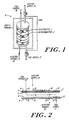
- FIG. 1 is a simplified view of an electrochemical energy converter according to the invention.
- FIG. 2 is a cross-sectional view of an electrolyte component and an interconnector component of an electrochemical cell stack
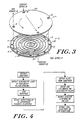
- FIG. 3 is a more detailed isometric view of the electrolyte and interconnector component.
- FIG. 4 is a schematic block diagram of an electrolyte fabrication process
- FIG. 5 is a graph of temperature and deposition conditions over time for an electrolyte fabrication process.
- FIG. 6 shows the relationship of the power-to-weight ratio to the thickness of the electrolyte and interconnector components.
- FIG. 7 is a graph of temperature versus stress experienced by an electrolyte plate during assembly.
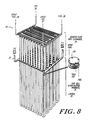
- FIG. 8 is a schematic, isometric view of an electrochemical converter module useful in systems according to the invention.
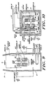
- FIG. 9 is a schematic illustration of a steam powered electricity generating system incorporating an electrochemical converter module according to the invention.
- FIG. 10 is a schematic illustration of a co-generation system incorporating an electrochemical converter module according to the invention.
- FIG 11 is a schematic illustration of a coal gasification system incorporating an electrochemical converter module according to the invention.
- In FIG. 1, an
electrochemical converter 10 of the present invention employing the compact, lightweight components is shown consisting of alternating electrolyte plates 1 andinterconnector plates 2. Holes through the plates form the passages for fuel and oxidizer gases. Grooves in the interconnector plates facilitate the distribution and collection of the gases. The cell stacks can be assembled in compression or by fusion thereby maintaining the electrical contacts and gas seals. - In FIGS. 2 and 3, the basic cell unit in the electrochemical cell stack is shown comprising a single electrolyte plate 1, and a
single interconnector plate 2. The electrolyte plate 1 can be made of stabilized zirconia ZrO
porous oxidizer electrode 4 and aporous fuel electrode 5 are coated. Preferred materials for the oxidizer electrodes are perovskites such as LaMnO₃(Sr). Preferred materials for fuel electrodes are cermets such as ZrO₂/Ni. Theinterconnector plate 2 preferably is made of a metal such as Inconel, a nickel alloy or a platinum alloy or made of a non-metallic conductor, such as silicon carbide. It serves as the electric connector between adjacent electrolyte plates and as a partition between the fuel and oxidizer gases as well as providing a heat conduction path along the electrode surfaces 4, 5 and to the outer edges of theplates 1 and 2. - Fuel can be supplied to the cell stack through an axial (with respect to the stack)
manifold 17 coupled to the stack viaholes 13 and the fuel product is exhausted throughmanifold 18 viaholes 14. The fuel is distributed over thefuel electrode surface 5 through an in-plane groove network 6 formed in the upper surface of theinterconnector plate 2. The notches 8 made in ridges 7 provide openings into the groove network 6 connectingholes fuel electrode 5. The oxidizer is fed to the stack frommanifold 19 viaholes 15 and its product is exhausted throughmanifold 20 viaholes 16. The oxidizer is distributed over the oxidizer electrode surface of the next electrolyte plate through a complementary in-plane groove network 9 formed in the lower surface of theconductor plate 2. A similar network on the lower surface of the adjacent cell above provides the passages for the oxidizer along electrolyte plate 1 as shown in FIG. 3. The outer ridges of the groove networks 6 and 9 on theinterconnector plates 2 are brought in contact with electrolyte plates 1 to form the sealed outer walls of stack assembly. The ridges 7 are pressed against the electrodes in assembly to achieve electrical contacts. The stack can be secured by water-cooled tension rods (not shown) which are disposed in bolt holes 12 to provide the assembly force. - It is to be understood that the apparatus of this invention can be utilized as a fuel cell (electric generator) when gaseous fuel is supplied or be applied as an electrolyzer (fuel synthesizer) when electricity is applied. It is applicable to all reversible reactions involving exchanging of oxygen such as:
H₂ + 1/2 O₂ = H₂O
SO₂ + 1/2 O₂ = SO₃
CO₂ + 1/2 O₂ = CO₂
and
NH₃ + 5/4 O₂ = NO + 3/2 H₂O
- To achieve compact, lightweight and efficient devices, components with thin structure are desired. The volumetric power density (Pv) of the planar cell stack is determined by the surface power density (Ps) of the electrolyte and the geometrical factors. The relationship can be represented by the equation:

where S is the height of a cell unit in a planar stack and V is the volumetric packaging efficiency. For an assembly of planar cell stack with a modest Ps of 0.2 W/cm², and V of 0.7, Pv equals 1.0 W/cm³ or 1000 kW/m³ when S, the unit cell height, is 0.15 cm or 1500 um. The cell unit height S, is determined by the sum of the thicknesses of the electrolyte and interconnector plates. - The thin electrolyte plates can be prepared using a high energy plasma-spray technique. For example, a powder comprising zirconia stabilized with magnesia, calcia or yttria is first suspended in a working gas such as nitrogen or argon and the suspension then is passed through an arc discharge. The oxide particles are heated by the discharged gas to their molten state and ejected from a nozzle onto a substrate, which has a surface corresponding to the desired configuration of the final electrolyte plate. The arc discharge is typically at least about 30 kilowatts, preferably at least 50 kilowatts to generate a high energy plasma spray.
- It has been found that a suitable high energy plasma spray can be generated employing an arc discharge having a voltage of at least 30 volts and a current of at least 800 amperes. Such a plasma spray can be generated by a variety of commercial devices, such as the Bay State Plasma Spray System manufactured by Bay State Abrasives, a Division of Dresser Industries, Inc., Westborough, Massachusetts. Preferably, the oxide powders used in plasma spray process should have a mean particle size ranging from about 40 to about 100 micron (µm) and the spray rate can range from 2 to about 8 pounds (3.63 Kg) per hour.
- In FIG. 4, a block diagram is presented of an electrolyte plate manufacturing process. The process begins with a substrate, preferably a substrate with proper adhesion with the solid oxide to be deposited. The substrate allows particles to adhere until a continuous coating of the desired thickness is obtained while permitting subsequent removal of the electrolyte plate by thermal or mechanical means without fracturing. For example, a suitable substrate surface can be achieved with graphite. Generally, the degree of roughness which is desired is between about 2.5 microns and about 25 microns finish. The substrate is preferably preheated to about 150°C-300°C prior to the commencement of oxide deposition.
- As noted above, the solid oxide electrolyte is deposited onto the substrate by a high energy plasma spray. In one process, the plate is obtained by a multiple step deposition. For example, when the temperature of the substrate exceeds about 250°C, spraying is interrupted and the workpiece (substrate) is allowed to cool, typically to about 230°C. The electrolyte plates can be cooled during the deposition process, for example, by passing a coolant through the substrate or by passing a non-reactive gas over the plate between the deposition of each layer. Once the workpiece is sufficiently cooled, another layer is deposited. This process is continued until a plate of sufficient thickness (e.g., 50 to 750 microns (µm) is obtained. Alternatively, the plate can be formed by a continous deposition process in which the substrate and/or plate are continuosly cooled to maintain a constant temperature during deposition. The plate can be detached from the substrate by a mechanical impact or thermal quenching to induce sufficient stress at the interface to overcome the adhesion between the plate and substrate. The plate is typically sintered next at about 1400°C to 1600°C to further densify the electrolyte material. The solid-oxide plate obtained by the multiple step spraying process has a density approaching about 90% theoretical density. During sintering, the solid-oxide plate experiences a linear shrinkage of about 2% which results in a product approaching about 96% theoretical density.
- After sintering, the plates are lapped slightly to produce a smooth surface and then a fuel electrode and oxidizer electrode are deposited on opposite sides of each plate, for example, by a flame deposition technique or a slurry application technique which produces coatings of a desired porosity of about 30-40 percent.
- In FIG. 5, the spray deposition process is further illustrated by a graph which plots temperature and the spray operation over time. Preheating can be conveniently achieved by impinging hot gas on the substrate using the plasma spray gas without the oxide powder. The interim cooling steps can be accomplished by natural convection, forcing a non-reactive room temperature gas over the workpiece or by a coolant circulating network integrated into the substrate.
- The preferred materials for the thin interconnector plates were selected based on the following requirements: 1) strength as well as electrical and thermal conductivity were necessary at 1000°C, which is the operating temperature of the converter; 2) good oxidation resistance was also necessary up to the working temperature; 3) chemical stability with fuel species was required; and 4) manufacturing economy when formed into the corrugated plate configuration, likewise was needed.
- Three types of materials, nickel and platinum alloys and silicon carbide were found to be most suitable. The relevant material properties are listed below in Table I.

- It has been found that nickel alloys of 200 to 500 microns thickness, platinum alloys of 25 to 150 microns (µm) and silicon carbide of 50 to 300 microns (µm) can be applied to form corrugated plates of 1000 microns (µm) in height. The corrugated interconnectors exhibit excellent stiffness in spite of thin materials. Silicon carbide is virtually impermeable to hydrogen and is stable to oxidation even at high temperature. The permeation of hydrogen through the metallic interconnectors is limited to a small portion of the fuel consumption rate. Nickel, which forms a thin, protective, and insulative coating in an oxidation environment, requires thin (10 microns (µm) or less) coatings such as silver, gold, or platinum on contact surfaces.
- Results of a weight analysis are presented in FIG. 6. The study selected the electrolyte thickness as a variable. Based on thermal and structural requirements, a nickel interconnector having a thickness twice that of the electrolyte was selected; the platinum interconnector thickness was chosen to be about one half that of the electrolyte and the silicon interconnector is preferably equal to the electrolyte plate thickness. The power-to-weight ratio of an unpackaged system, excluding the insulation enclosure, heat exchanger or piping, was computed. For example, as shown in the figure, devices of better than 2000 W/kg of an unpackaged weight, can be achieved with silicon carbide or platinum interconnectors. The nickel system can achieve 350 W/kg.
- The corrugated top and bottom patterns of the interconnectors can be obtained, for example, by stamping the nickel or platinum alloy sheets with one or more sets of matched male and female dies. The dies are prefabricated according to the desired configuration of the product, and can be hardened by heat treatment to withstand the repetitive compressing actions in mass productions. The stamp forming process for the interconnectors preferably is conducted in multiple steps due to the geometrical complexity of the gas passage networks. For example, grooves are formed in initial strokes, which are followed by notch forming to provide gas cross-flow passages. Holes in the interconnectors are punched out at the final step. Temperature annealling is recommended between the consecutive steps to prevent the overstressing of sheet metal. The stamping method is capable of producing articles of complex geometry while maintaining uniform material thickness. Alternatively, corrugated interconnectors can be formed by electrodepostion on an initially flat metal plate using a set of suitable masks. Silicon carbide interconnector plates can be formed by vapor deposition onto preshaped substrates, by sintering of bonded powders, or by self bonding processes.
- The converter stack are assembled at a high temperature which serves not only to fuse the adjacent plates together (and thereby achieve gas sealing and electrical contact) but also places the electrolyte plates in a favorable prestressed condition. This technique is most useful when metallic interconnector plates are disposed between the zirconia electrolyte plates since it takes advantage of the large differences in their respective thermal expansion coefficients. FIG. 7 shows the stress changes which will occur in a typical zirconia electrolyte during high temperature assembly. The stack is preferably assembled at a temperature above 1000°C and fusion of adjacent plates is achieved by a metallic flux (e.g. nickel powder) coated the ridges of plates. After the plates have been fused together and the assembly is cooled, the electrolyte plates experience in-plane compression. During operational excursions, as shown in FIG. 7, the electrolyte will remain in compression, a favorable stress state for ceramic materials.
- In Figure 8 an
electrochemical converter module 20 is shown having stacked electrolyte and interconnector plates as its components. In general, the structures and configurations shown in Figure 8 are similar to those described in U.S. Patent 4,490,445 cited above and incorporated by reference. Themodule 20 includeshairpin pendants 21 with U bends 22 to achieve better structural rigidity and more convenient one-side terminations for gas manifolding and electrical connections. Bus bars 23 are provided to tap or supply electricity to the electrochemical pendant stacks 21 which are in multiple parallel electrical connection. Themodule 20 is designed to operate efficiently at an elevated temperature (about 1,000 degrees C.). Heat exchanger stacks 24 are provided and serve as a thermal conduction buffer between the hot electrochemical cell stacks 21 and the incoming gases. In the illustrated arrangement the incoming reaction gases are heated by the outgoing spent product gases in a counterflow scheme similar to that described in U.S. Patent 4,490,445. Theheat exchanger stack 24 can be constructed from flat heat exchanger plates which are arranged in alternating layers with partition plates. Internal passages for the feeding and exhausting of gases and grove networks for the distribution of gases over the heat exchanger plates can be provided substantially identical to the grove and ridge patterns described above in connection with the plates of the electrochemical converter. Similarly, ridges on the heated partition plates can be pressed against the adjacent heat exchanger plates to provide circumferential gas seals. - In Figure 9 a module such as that described in Figure 8 is shown incorporated in a fossil fuel-fired, electricity-generating
system 30.Electrochemical fuel cells 21 and heat exchangers 24 (preferably in a modular configuration as shown in Figure 8) are disposed within thecombustion chamber 31. Within the chamber 31 a combustion furnace burns fuel 33 andair 35 to generate steam. Energy is extracted from the steam in asteam bottoming plant 37 to provide an electrical output. At the same time, a portion of the fuel supply 33 is conditioned by afuel conditioner 34 and fed via theheat exchangers 24 to the electrochemical (fuel cell)converter 21. A portion of theair supply 35 is similarly passed through theheat exchanger 24 and into the converter for reaction with the fuel therein. The electrical output of the converter is transferred to aninverter 36 to generate an alternating current electrical output. The spent gases from the fuel cell are fed into the combustion furnace for further extraction of thermodynamic energy. The converter produces electricity at about 1000°C by an exothermic process due to the electrochemical characteristics of the reactions and the internal resistance. The heat is convectively transferred to the combustion reactants which flow by the converter, which reactants in turn generate steam in subsequent sections of the flow duct. This system offers efficient energy coupling, economic mechanical intergration, and high efficiency in conversion of fuel to electricity, not limited to Carnot cycle constraints. - Figure 10 shows a steam-cogeneration system useful, for example, in generating steam for industrial or residential uses, which also incorporates an electrochemical converter of the invention within the
combustion chamber 41. In this configuration,fuel supply 42 is first fed viaheat exchangers 24 into theconverter 21 and air fromair supply 43 is likewise fed through theexchangers 24 into theconverter 21. As in Figure 9, the electricity generated by the converter is converted to alternating current electrical output byconverter 36. In thiscogeneration system 40 the converter again produces electricity at about 1000°C by an exothermic process. However, in this system the heat is radiantly transferred to water tubes distributed within the furnace. Steam is generated in the water tubes and collected in theboiler drum 46. The spent gases from the converter are also burned within thecombustion chamber 41 to provide additional energy necessary to generatefurther steam 48 fromwater 47 inboiler 46. This steam can be used directly in industrial applications for various processes or can be used, for example, in residential or commercial applications for heating or the like. - In Figure 11 a
coal gasification system 50 is shown which incorporates the electrochemical converters of the present invention. Again, theconverter cells 21 andheat exchanger 23 are disposed within a combustion chamber 51. Within this chamber, a coal-fedgasifier 52 converts coal into gas. A portion or the total of this gas output is fed into theconverter 21 via theheat exchanger 24 while air fromair supply 54 is also provided. Again, the electrical output of the converter is transferred to theinverter 36 to provide alternating current electrical output. As shown, the heat generated within the gasifier can also be used by asteam turbine 55 to provide an additional electrical output.
Claims (14)
- A method of constructing an electrochemical converter, including:a) forming a set of solid-oxide electrolyte plates, for example, by suspending a solid oxide powder in a gas, generating a plasma spray from the gas suspension and depositing the solid oxide upon a substrate, and then removing the plates from the substrate and coating said electrolyte plates with a fuel electrode material on one surface of each plate and an oxidizer electrode material on a second surface of each plate, andb) forming a set of interconnector plates having corrugated structures comprising at least one electrically conducting material, the corrugated structure defining groove networks for the passage of gases and ridges for gas seals and electrical contact with the electrode coatings of the electrolyte plates, characterized byc) forming the electrolyte and interconnector plates from materials that exhibit sufficiently large differences in their respective thermal expansion coefficients, and assembling the converter by stacking alternating layers of the electrolyte and interconnector plates together and fusing the adjacent plates to each other at an elevated temperature whereby the solid electrolyte is prestressed in compression when cooled so that it remains free of tensile stress through its operating temperature excursion.
- The method of claim 1 wherein the step of assembly further comprises assembling the stack at a temperature of about 800°C or higher.
- The method of claim 2 wherein the step of assembly further comprises assembling the stack at a temperature of about 1000°C or higher.
- The method of any preceding claim wherein a flux material is employed to achieve fusion of the adjacent plates.
- The method of any preceding claim wherein the a) step includes depositing the solid oxide upon a substrate until plates of about 50 to about 750 microns in thickness are deposited, and then removing the plates from the substrate.
- The method of any preceding claim wherein the c) step includes choosing said at least one electrically conducting material from the group of nickel alloys, silicon carbide and platinum alloys, the corrugated interconnector plates having thickness ranging from about 100 to about 1000 microns in the case of nickel alloy, and having a thickness ranging from about 50 to 300 microns in the case of silicon carbide and having a thickness ranging from about 25 to about 250 microns in the case of platinum alloys.
- The method claim 6 wherein the corrugated patterns of the interconnector plates are defined by silicon carbide deposition on a preshaped substrate.
- The method of claim 6 wherein the corrugated patterns of the interconnector plates are defined by molding and then sintering a silicon carbide compact.
- An electrochemical converter having:a) a set of solid-oxide electrolyte plates formed by suspending a solid oxide powder in a gas, passing the suspension through an arc discharge to generate a plasma spray and depositing the solid oxide on a substrate, removing the plates from the substrate; and then coating said electrolyte plates with a fuel electrode material on one surface of each plate and an oxidizer electrode material on a second surface of each plate; andb) a set of interconnector plates having corrugated structures, comprising at least one electrically conductive material, the corrugated structure defining groove networks for the passage of gases and ridges for gas seals and electrical contact with the electrode coatings of the electrolyte plates; characterized in that the electrolyte plates are prestressed in compression, the converter being assembled by stacking alternating layers of the electrolyte and interconnector plates together and fusing adjacent plates to each other at an elevated temperature whereby the solid electrolyte is prestressed in compression when cooled so that it remains in compression through its operating temperature excursion.
- The converter of claim 9, wherein the solid-oxide electrolyte plates have a thickness of about 50 to about 750 microns.
- The converter of claim 9 or 10, wherein the material of the interconnector plates is chosen from the group of platinum and nickel alloys and silicon carbide composites, the metal plates having a thickness ranging from about 100 to about 1000 microns in the case of nickel alloy, having a thickness ranging from about 50 to 300 microns in the case of silicon carbide, and having a thickness ranging from about 25 to about 250 microns in the case of platinum alloys.
- An electricity generating system comprisinga) a fossil fuel-fired steam power plant including a boiler having a combustion furnace;b) an electrochemical converter as claimed in claim 9 or 10 disposed within the combustion furnace of said power plant, andc) a fuel supply connected to the converter to provide a source of fuel for electrochemical conversion and connected to said furnace to provide a source of fuel for generation of steam from water in said boiler.
- A cogeneration system comprisinga) a boiler having a combustion furnace to generate steam, thereby providing energy for at least one external process;b) an electrochemical converter as claimed in claim 9, 10, or 11 disposed within the combustion furnace of said boiler; andc) a fuel supply connected to the converter to provide a source of fuel for electrochemical conversion and connected to said furnace to provide a source of fuel to generate steam from water in the boiler.
- A coal gasification system comprisinga) a coal-fed gasifier having a chamber in which coal is converted into a combustible gas;b) an electrochemical converter as claimed in claim 9, 10 or 11 disposed within the chamber of said gasifier; andc) means for supplying at least a portion of said combustible gas from said gasifier to said converter as a fuel for electrochemical conversion.
Priority Applications (1)
| Application Number | Priority Date | Filing Date | Title |
|---|---|---|---|
| AT86903789T ATE66497T1 (en) | 1985-05-17 | 1986-05-09 | ELECTROCHEMICAL CONVERTERS AND COMBINED CIRCUIT SYSTEMS. |
Applications Claiming Priority (2)
| Application Number | Priority Date | Filing Date | Title |
|---|---|---|---|
| US06/735,441 US4629537A (en) | 1985-05-17 | 1985-05-17 | Compact, light-weight, solid-oxide electrochemical converter |
| US735441 | 1985-05-17 |
Publications (3)
| Publication Number | Publication Date |
|---|---|
| EP0222880A1 EP0222880A1 (en) | 1987-05-27 |
| EP0222880A4 EP0222880A4 (en) | 1987-12-17 |
| EP0222880B1 true EP0222880B1 (en) | 1991-08-21 |
Family
ID=24955816
Family Applications (1)
| Application Number | Title | Priority Date | Filing Date |
|---|---|---|---|
| EP86903789A Expired - Lifetime EP0222880B1 (en) | 1985-05-17 | 1986-05-09 | Electrochemical converters and combined cycle systems |
Country Status (6)
| Country | Link |
|---|---|
| US (4) | US4629537A (en) |
| EP (1) | EP0222880B1 (en) |
| JP (1) | JPH0782872B2 (en) |
| AT (1) | ATE66497T1 (en) |
| DE (1) | DE3680992D1 (en) |
| WO (1) | WO1986006762A1 (en) |
Cited By (1)
| Publication number | Priority date | Publication date | Assignee | Title |
|---|---|---|---|---|
| US6878480B2 (en) | 1999-12-06 | 2005-04-12 | Technology Management, Inc. | Electrochemical apparatus with reactant micro-channels |
Families Citing this family (117)
| Publication number | Priority date | Publication date | Assignee | Title |
|---|---|---|---|---|
| US4629537A (en) * | 1985-05-17 | 1986-12-16 | Hsu Michael S | Compact, light-weight, solid-oxide electrochemical converter |
| US4770955A (en) * | 1987-04-28 | 1988-09-13 | The Standard Oil Company | Solid electrolyte fuel cell and assembly |
| US4857420A (en) * | 1987-10-13 | 1989-08-15 | International Fuel Cell Corporation | Method of making monolithic solid oxide fuel cell stack |
| JP2661692B2 (en) * | 1987-10-14 | 1997-10-08 | 東燃株式会社 | Electrode assembly for high temperature fuel cells |
| US4950562A (en) * | 1988-04-21 | 1990-08-21 | Toa Nenryo Kogyo Kabushiki Kaisha | Solid electrolyte type fuel cells |
| DE68909720T2 (en) * | 1988-07-23 | 1994-02-03 | Fuji Electric Co Ltd | Solid electrolyte fuel cell. |
| US5049458A (en) * | 1988-08-31 | 1991-09-17 | Nkk Corporation | Fuel cell |
| US4937152A (en) * | 1988-09-26 | 1990-06-26 | Nkk Corporation | Fuel cell |
| EP0374636A1 (en) * | 1988-12-20 | 1990-06-27 | Asea Brown Boveri Ag | Process for the conversion of the chemical potential energy of a material into electrical energy by a high-temperature electrochemical process |
| EP0381850A1 (en) * | 1989-02-06 | 1990-08-16 | Asea Brown Boveri Ag | Device for converting energy by means of high-temperature fuel cells, and structural elements sandwiched therebetween for conducting gaseous fluids |
| DE3914244A1 (en) * | 1989-04-29 | 1990-10-31 | Asea Brown Boveri | FUEL CELL ARRANGEMENT AND METHOD FOR THE PRODUCTION THEREOF |
| EP0410166A1 (en) * | 1989-07-24 | 1991-01-30 | Asea Brown Boveri Ag | Construction element for current conduction for high temperature fuel cells |
| EP0411374A1 (en) * | 1989-07-31 | 1991-02-06 | Asea Brown Boveri Ag | Current conduction element for high temperature ceramic fuel cells |
| DE3929730A1 (en) * | 1989-09-07 | 1991-03-21 | Kernforschungsz Karlsruhe | HYDROGEN / OXYGEN FUEL CELL |
| EP0418528A1 (en) * | 1989-09-11 | 1991-03-27 | Asea Brown Boveri Ag | Current collector for ceramic fuel cells |
| EP0423448A1 (en) * | 1989-09-20 | 1991-04-24 | Asea Brown Boveri Ag | Collection for the conduction of current between high temperature fuel cells arranged in a pile and method for producing the same |
| DE4009138A1 (en) * | 1989-10-26 | 1991-09-26 | Siemens Ag | FIXED ELECTROLYTE HIGH TEMPERATURE FUEL CELL MODULE |
| EP0424732A1 (en) * | 1989-10-27 | 1991-05-02 | Asea Brown Boveri Ag | Current conduction element for stacked hightemperature fuel cells and method of manufacture |
| CH678775A5 (en) * | 1990-01-09 | 1991-10-31 | Sulzer Ag | |
| DE4002951A1 (en) * | 1990-02-01 | 1991-08-08 | Medicoat Ag Niederrohrdorf | SOLID ELECTROLYTE - FUEL CELL AND METHOD FOR THE PRODUCTION THEREOF |
| EP0440968A1 (en) * | 1990-02-08 | 1991-08-14 | Asea Brown Boveri Ag | Element for obtaining a possible uniform temperature distribution on the surface of a plate-like ceramic high temperature fuel cell |
| US5064732A (en) * | 1990-02-09 | 1991-11-12 | International Fuel Cells Corporation | Solid polymer fuel cell system: high current density operation |
| EP0450336B1 (en) * | 1990-03-13 | 1994-08-17 | Mitsubishi Jukogyo Kabushiki Kaisha | Power generation system with flat fuel cells of solid electrolyte |
| EP0446680A1 (en) * | 1990-03-15 | 1991-09-18 | Asea Brown Boveri Ag | Current collector for conducting current between neighbouring piled high temperature fuel cells |
| JPH0443566A (en) * | 1990-06-06 | 1992-02-13 | Murata Mfg Co Ltd | Solid electrolyte type fuel cell |
| US5085742A (en) * | 1990-10-15 | 1992-02-04 | Westinghouse Electric Corp. | Solid oxide electrochemical cell fabrication process |
| US5256499A (en) * | 1990-11-13 | 1993-10-26 | Allied Signal Aerospace | Monolithic solid oxide fuel cells with integral manifolds |
| JP3295945B2 (en) * | 1991-02-22 | 2002-06-24 | 株式会社村田製作所 | Distributor of solid oxide fuel cell and method of manufacturing the same |
| JPH05135787A (en) * | 1991-03-28 | 1993-06-01 | Ngk Insulators Ltd | Manufacture of solid electrolyte film and manufacture of solid electrolyte fuel cell |
| US5230849A (en) * | 1991-06-04 | 1993-07-27 | Michael S. Hsu | Electrochemical converter assembly and overlay methods of forming component structures |
| US5202194A (en) * | 1991-06-10 | 1993-04-13 | Halliburton Company | Apparatus and method for providing electrical power in a well |
| JP3253985B2 (en) * | 1991-10-11 | 2002-02-04 | 関西電力株式会社 | Power storage device |
| US5332630A (en) * | 1991-11-04 | 1994-07-26 | Hsu Michael S | On-board recharging system for battery powered electric vehicles |
| JPH05174852A (en) * | 1991-12-17 | 1993-07-13 | Yoshida Kogyo Kk <Ykk> | Conductive connecting material for solid electrolyte fuel cell |
| EP0580918B1 (en) * | 1992-07-27 | 1995-12-13 | Sulzer Innotec Ag | Device comprising high-temperature fuel cells |
| JPH06103990A (en) * | 1992-09-18 | 1994-04-15 | Ngk Insulators Ltd | Solid electrolytic type fuel cell and manufacture thereof |
| DK0671058T3 (en) * | 1992-11-25 | 1997-02-17 | Michael S Hsu | Integration of thermal radiation with regenerative heating in an electrochemical high temperature converter |
| JPH07506214A (en) * | 1993-02-15 | 1995-07-06 | フセルコ・アクチエンゲゼルシヤフト | Method and apparatus for converting chemical energy of fuel into thermal energy and simultaneously directly into electrical energy |
| US5338622A (en) * | 1993-04-12 | 1994-08-16 | Ztek Corporation | Thermal control apparatus |
| US6171468B1 (en) | 1993-05-17 | 2001-01-09 | Electrochemicals Inc. | Direct metallization process |
| US6303181B1 (en) | 1993-05-17 | 2001-10-16 | Electrochemicals Inc. | Direct metallization process employing a cationic conditioner and a binder |
| US5476580A (en) * | 1993-05-17 | 1995-12-19 | Electrochemicals Inc. | Processes for preparing a non-conductive substrate for electroplating |
| US5690805A (en) * | 1993-05-17 | 1997-11-25 | Electrochemicals Inc. | Direct metallization process |
| US6710259B2 (en) | 1993-05-17 | 2004-03-23 | Electrochemicals, Inc. | Printed wiring boards and methods for making them |
| US5725807A (en) * | 1993-05-17 | 1998-03-10 | Electrochemicals Inc. | Carbon containing composition for electroplating |
| US5366819A (en) * | 1993-10-06 | 1994-11-22 | Ceramatec, Inc. | Thermally integrated reformer for solid oxide fuel cells |
| US5480738A (en) * | 1994-02-04 | 1996-01-02 | Ceramatec, Inc. | Fuel cell module |
| US5426003A (en) * | 1994-02-14 | 1995-06-20 | Westinghouse Electric Corporation | Method of forming a plasma sprayed interconnection layer on an electrode of an electrochemical cell |
| US5389456A (en) * | 1994-02-14 | 1995-02-14 | Westinghouse Electric Corporation | Method and closing pores in a thermally sprayed doped lanthanum chromite interconnection layer |
| US5391440A (en) * | 1994-02-14 | 1995-02-21 | Westinghouse Electric Corporation | Method of forming a leak proof plasma sprayed interconnection layer on an electrode of an electrochemical cell |
| US5693201A (en) * | 1994-08-08 | 1997-12-02 | Ztek Corporation | Ultra-high efficiency turbine and fuel cell combination |
| JP3700858B2 (en) * | 1994-03-21 | 2005-09-28 | ジーテック コーポレーション | Electrochemical converter with optimal pressure distribution |
| US5501781A (en) * | 1994-08-08 | 1996-03-26 | Ztek Corporation | Electrochemical converter having internal thermal integration |
| US5948221A (en) * | 1994-08-08 | 1999-09-07 | Ztek Corporation | Pressurized, integrated electrochemical converter energy system |
| US6083636A (en) | 1994-08-08 | 2000-07-04 | Ztek Corporation | Fuel cell stacks for ultra-high efficiency power systems |
| US5763114A (en) * | 1994-09-01 | 1998-06-09 | Gas Research Institute | Integrated reformer/CPN SOFC stack module design |
| US5496655A (en) * | 1994-10-12 | 1996-03-05 | Lockheed Idaho Technologies Company | Catalytic bipolar interconnection plate for use in a fuel cell |
| US5747185A (en) * | 1995-11-14 | 1998-05-05 | Ztek Corporation | High temperature electrochemical converter for hydrocarbon fuels |
| US5612149A (en) * | 1996-01-02 | 1997-03-18 | Ceramatec, Inc. | Fuel cell column heat exchanger mated module |
| DE19611591A1 (en) * | 1996-03-23 | 1997-09-25 | Dornier Gmbh | High temperature fuel cell system |
| US5858314A (en) | 1996-04-12 | 1999-01-12 | Ztek Corporation | Thermally enhanced compact reformer |
| US6054229A (en) * | 1996-07-19 | 2000-04-25 | Ztek Corporation | System for electric generation, heating, cooling, and ventilation |
| US6380637B1 (en) | 1996-09-19 | 2002-04-30 | Ztek Corporation | Off-board station and an electricity exchanging system suitable for use with a mobile vehicle power system |
| US5858568A (en) | 1996-09-19 | 1999-01-12 | Ztek Corporation | Fuel cell power supply system |
| US5736268A (en) * | 1996-09-26 | 1998-04-07 | M-C Power Corporation | High temperature fuel cell stack power bus |
| US6344290B1 (en) | 1997-02-11 | 2002-02-05 | Fucellco, Incorporated | Fuel cell stack with solid electrolytes and their arrangement |
| JP3453283B2 (en) | 1997-08-08 | 2003-10-06 | 三菱重工業株式会社 | Solid oxide fuel cell |
| US5770327A (en) * | 1997-08-15 | 1998-06-23 | Northwestern University | Solid oxide fuel cell stack |
| USRE39556E1 (en) * | 1997-11-20 | 2007-04-10 | Relion, Inc. | Fuel cell and method for controlling same |
| US6096449A (en) * | 1997-11-20 | 2000-08-01 | Avista Labs | Fuel cell and method for controlling same |
| US6030718A (en) * | 1997-11-20 | 2000-02-29 | Avista Corporation | Proton exchange membrane fuel cell power system |
| DE29802444U1 (en) * | 1998-02-12 | 1999-04-01 | Siemens Ag | High temperature fuel cell and high temperature fuel cell stack |
| GB9808133D0 (en) * | 1998-04-18 | 1998-06-17 | Normalair Garrett Ltd | Ionic conduction device |
| US6146779A (en) * | 1999-04-01 | 2000-11-14 | Plug Power Inc. | Fluid flow plate, fuel cell assembly system, and method employing same for controlling heat in fuel cells |
| US6399233B1 (en) | 1999-07-29 | 2002-06-04 | Technology Management, Inc. | Technique for rapid cured electrochemical apparatus component fabrication |
| US6440596B1 (en) | 1999-10-20 | 2002-08-27 | Technology Management, Inc. | Solid-oxide fuel cell hot assembly |
| US6489050B1 (en) * | 1999-11-01 | 2002-12-03 | Technology Management, Inc. | Apparatus and method for cooling high-temperature fuel cell stacks |
| US6355368B1 (en) | 1999-11-05 | 2002-03-12 | Plug Power Inc. | Cooling method and apparatus for use with a fuel cell stack |
| US6575248B2 (en) * | 2000-05-17 | 2003-06-10 | Schlumberger Technology Corporation | Fuel cell for downhole and subsea power systems |
| US7096955B2 (en) * | 2000-05-17 | 2006-08-29 | Schlumberger Technology Corporation | Long duration fuel cell system |
| US7326480B2 (en) | 2000-05-17 | 2008-02-05 | Relion, Inc. | Fuel cell power system and method of controlling a fuel cell power system |
| US6468682B1 (en) | 2000-05-17 | 2002-10-22 | Avista Laboratories, Inc. | Ion exchange membrane fuel cell |
| US6485853B1 (en) | 2000-06-27 | 2002-11-26 | General Motors Corporation | Fuel cell system having thermally integrated, isothermal co-cleansing subsystem |
| US6677069B1 (en) * | 2000-08-18 | 2004-01-13 | Hybrid Power Generation Systems, Llc | Sealless radial solid oxide fuel cell stack design |
| WO2002019455A2 (en) * | 2000-08-30 | 2002-03-07 | Siemens Aktiengesellschaft | Method for producing a solid ceramic fuel cell |
| US6551734B1 (en) * | 2000-10-27 | 2003-04-22 | Delphi Technologies, Inc. | Solid oxide fuel cell having a monolithic heat exchanger and method for managing thermal energy flow of the fuel cell |
| US6811913B2 (en) * | 2000-11-15 | 2004-11-02 | Technology Management, Inc. | Multipurpose reversible electrochemical system |
| US6544681B2 (en) | 2000-12-26 | 2003-04-08 | Ballard Power Systems, Inc. | Corrugated flow field plate assembly for a fuel cell |
| US6677070B2 (en) * | 2001-04-19 | 2004-01-13 | Hewlett-Packard Development Company, L.P. | Hybrid thin film/thick film solid oxide fuel cell and method of manufacturing the same |
| US9113577B2 (en) * | 2001-11-27 | 2015-08-18 | Thermotek, Inc. | Method and system for automotive battery cooling |
| US20040101617A1 (en) * | 2001-11-27 | 2004-05-27 | Devi P Sujatha | Direct synthesis and deposition of luminescent films |
| US7479304B2 (en) * | 2002-02-14 | 2009-01-20 | Applied Materials, Inc. | Gas distribution plate fabricated from a solid yttrium oxide-comprising substrate |
| US7222406B2 (en) * | 2002-04-26 | 2007-05-29 | Battelle Memorial Institute | Methods for making a multi-layer seal for electrochemical devices |
| US7195693B2 (en) * | 2002-06-05 | 2007-03-27 | Advanced Thermal Sciences | Lateral temperature equalizing system for large area surfaces during processing |
| US7595122B2 (en) * | 2002-06-11 | 2009-09-29 | General Electric Company | Interconnect supported electrolyzer assembly, preform and method of fabrication |
| US20040081872A1 (en) * | 2002-10-28 | 2004-04-29 | Herman Gregory S. | Fuel cell stack with heat exchanger |
| US7144649B2 (en) * | 2002-11-27 | 2006-12-05 | Utc Fuel Cells, Llc | Interconnect for solid oxide fuel cells |
| US20040200187A1 (en) * | 2002-11-27 | 2004-10-14 | Warrier Sunil G. | Compliant, strain tolerant interconnects for solid oxide fuel cell stack |
| US7008711B2 (en) * | 2003-01-27 | 2006-03-07 | Gas Technology Institute | Thermally integrated fuel cell power system |
| WO2005020364A1 (en) * | 2003-08-21 | 2005-03-03 | Shinko Electric Industries Co., Ltd. | Power generator by solid electrolytic fuel cell |
| US20050074658A1 (en) * | 2003-10-06 | 2005-04-07 | General Electric Company | Fuel cells with applied stress and methods of implementing the same |
| US7374834B2 (en) * | 2004-09-07 | 2008-05-20 | Gas Technology Institute | Gas flow panels integrated with solid oxide fuel cell stacks |
| GB0524486D0 (en) * | 2005-12-01 | 2006-01-11 | Rolls Royce Fuel Cell Systems | An electrolysis apparatus |
| US7654010B2 (en) * | 2006-02-23 | 2010-02-02 | Tokyo Electron Limited | Substrate processing system, substrate processing method, and storage medium |
| JP2010517208A (en) * | 2006-10-31 | 2010-05-20 | コーニング インコーポレイテッド | Micro-processed electrolyte sheet, fuel cell device using the same, and micro-processing method for producing fuel cell device |
| US10622194B2 (en) | 2007-04-27 | 2020-04-14 | Applied Materials, Inc. | Bulk sintered solid solution ceramic which exhibits fracture toughness and halogen plasma resistance |
| US10242888B2 (en) | 2007-04-27 | 2019-03-26 | Applied Materials, Inc. | Semiconductor processing apparatus with a ceramic-comprising surface which exhibits fracture toughness and halogen plasma resistance |
| US20090023013A1 (en) * | 2007-07-17 | 2009-01-22 | Ford Motor Company | Spray formed thin layers having fine features |
| US7914636B2 (en) * | 2007-09-11 | 2011-03-29 | Institute Of Nuclear Energy Research | Synergistic process and recipe for fabrication of a high integrity membrane electrode assembly of solid oxide fuel cell |
| US20090081512A1 (en) | 2007-09-25 | 2009-03-26 | William Cortez Blanchard | Micromachined electrolyte sheet, fuel cell devices utilizing such, and micromachining method for making fuel cell devices |
| TWI361511B (en) * | 2008-05-29 | 2012-04-01 | Green Hydrotec Inc | Fluid delivery device |
| WO2010141629A1 (en) | 2009-06-02 | 2010-12-09 | Thermochem Recovery International, Inc. | Gasifier having integrated fuel cell power generation system |
| DE102009043443A1 (en) | 2009-09-29 | 2011-03-31 | Volkswagen Ag | Method for cooling of battery module for vehicle, involves supplying cooling fluid for cooling of battery module from side of battery module |
| GB2476238B (en) * | 2009-12-15 | 2015-11-18 | Ge Oil & Gas Uk Ltd | Underwater power generation |
| FR2959244B1 (en) * | 2010-04-23 | 2012-06-29 | Commissariat Energie Atomique | PROCESS FOR PREPARING A MULTILAYER COATING ON A SURFACE OF A SUBSTRATE BY THERMAL PROJECTION |
| FR2985522B1 (en) * | 2012-01-09 | 2014-03-14 | Commissariat Energie Atomique | INSTALLATION OF HIGH TEMPERATURE WATER VAPOR ELECTROLYSIS (HVAC) WITH ALLOTHERMIC PRODUCTION OF HYDROGEN |
| WO2015061306A1 (en) | 2013-10-25 | 2015-04-30 | United Technologies Corporation | Plasma spraying system with adjustable coating medium nozzle |
Family Cites Families (35)
| Publication number | Priority date | Publication date | Assignee | Title |
|---|---|---|---|---|
| US2570543A (en) * | 1950-06-17 | 1951-10-09 | Consolidation Coal Co | Conversion of carbon to electrical energy |
| NL294315A (en) * | 1962-06-27 | 1900-01-01 | ||
| FR1367534A (en) * | 1963-05-17 | 1964-07-24 | Comp Generale Electricite | Electric fuel cell |
| US3464861A (en) * | 1964-08-20 | 1969-09-02 | Shell Oil Co | Fuel cells with solid state electrolytes |
| SE306107B (en) * | 1965-03-03 | 1968-11-18 | Asea Ab | |
| GB1130080A (en) * | 1965-12-10 | 1968-10-09 | Comp Generale Electricite | Composite hollow electrode for fuel cells, and cells produced by assembling such electrodes |
| CH446456A (en) * | 1966-09-20 | 1967-11-15 | Bbc Brown Boveri & Cie | High temperature fuel cell battery |
| US3589942A (en) * | 1966-12-22 | 1971-06-29 | Cons Natural Gas Svc | Bipolar collector plates |
| DE1671705A1 (en) * | 1967-03-18 | 1971-09-23 | Bbc Brown Boveri & Cie | Battery consisting of fuel cells connected electrically in series with solid electrolyte |
| US3460991A (en) * | 1967-08-16 | 1969-08-12 | Gen Electric | Fuel cell with tubular electrodes and solid electrolyte |
| US3525646A (en) * | 1967-08-31 | 1970-08-25 | Raffinage Cie Franc De | Battery of fuel cells of solid electrolyte and the process of making these |
| US3526549A (en) * | 1968-04-09 | 1970-09-01 | Us Interior | Solid electrolyte stacked disc fuel cells |
| US3616334A (en) * | 1968-07-05 | 1971-10-26 | Gen Electric | Electrically and chemically coupled power generator and hydrogen generator |
| US3607427A (en) * | 1969-02-06 | 1971-09-21 | Gen Electric | Electrically coupled fuel cell and hydrogen generator |
| US3784415A (en) * | 1971-01-28 | 1974-01-08 | Us Army | Method of making a high voltage deposited fuel cell component |
| US4042483A (en) * | 1973-07-20 | 1977-08-16 | Rhone-Progil | Electrolysis cell electrode and method of preparation |
| DE2514034C3 (en) * | 1975-03-29 | 1979-04-19 | Brown, Boveri & Cie Ag, 6800 Mannheim | Solid electrolyte battery |
| US3964930A (en) * | 1975-07-21 | 1976-06-22 | United Technologies Corporation | Fuel cell cooling system |
| US4056452A (en) * | 1976-02-26 | 1977-11-01 | Billings Energy Research Corporation | Electrolysis apparatus |
| CA1059943A (en) * | 1976-07-20 | 1979-08-07 | Pierre L. Claessens | Electrolytically forming peroxosulfuric acid to oxidize organic material in sulfuric acid |
| US4087976A (en) * | 1976-08-13 | 1978-05-09 | Massachusetts Institute Of Technology | Electric power plant using electrolytic cell-fuel cell combination |
| DE2735934C3 (en) * | 1977-08-10 | 1980-07-31 | Dornier System Gmbh, 7990 Friedrichshafen | Connection material for the electrical series connection of electrochemical cells |
| US4210512A (en) * | 1979-01-08 | 1980-07-01 | General Electric Company | Electrolysis cell with controlled anolyte flow distribution |
| US4310605A (en) * | 1980-09-22 | 1982-01-12 | Engelhard Minerals & Chemicals Corp. | Fuel cell system |
| US4490444A (en) * | 1980-12-22 | 1984-12-25 | Westinghouse Electric Corp. | High temperature solid electrolyte fuel cell configurations and interconnections |
| US4478918A (en) * | 1981-12-25 | 1984-10-23 | Tokyo Shibaura Denki Kabushiki Kaisha | Fuel cell stack |
| US4490445A (en) * | 1982-05-24 | 1984-12-25 | Massachusetts Institute Of Technology | Solid oxide electrochemical energy converter |
| US4614628A (en) * | 1982-05-26 | 1986-09-30 | Massachusetts Institute Of Technology | Solid electrolyte structure and method for forming |
| US4583583A (en) * | 1983-06-02 | 1986-04-22 | Engelhard Corporation | Fuel cell crimp-resistant cooling device with internal coil |
| US4482440A (en) * | 1983-10-06 | 1984-11-13 | Olin Corporation | Electrochemical cell and process for manufacturing temperature sensitive solutions |
| US4510212A (en) * | 1983-10-12 | 1985-04-09 | The United States Of America As Represented By The United States Department Of Energy | Solid oxide fuel cell having compound cross flow gas patterns |
| US4574112A (en) * | 1983-12-23 | 1986-03-04 | United Technologies Corporation | Cooling system for electrochemical fuel cell |
| JPS6130968U (en) * | 1984-07-28 | 1986-02-25 | 株式会社 富士電機総合研究所 | fuel cell stack |
| US4644751A (en) * | 1985-03-14 | 1987-02-24 | Massachusetts Institute Of Technology | Integrated fuel-cell/steam plant for electrical generation |
| US4629537A (en) * | 1985-05-17 | 1986-12-16 | Hsu Michael S | Compact, light-weight, solid-oxide electrochemical converter |
-
1985
- 1985-05-17 US US06/735,441 patent/US4629537A/en not_active Expired - Lifetime
-
1986
- 1986-05-09 WO PCT/US1986/001017 patent/WO1986006762A1/en active IP Right Grant
- 1986-05-09 EP EP86903789A patent/EP0222880B1/en not_active Expired - Lifetime
- 1986-05-09 JP JP61502917A patent/JPH0782872B2/en not_active Expired - Fee Related
- 1986-05-09 AT AT86903789T patent/ATE66497T1/en active
- 1986-05-09 DE DE8686903789T patent/DE3680992D1/en not_active Expired - Lifetime
- 1986-05-09 US US06/861,433 patent/US4721556A/en not_active Ceased
-
1988
- 1988-01-11 US US07/142,067 patent/US4853100A/en not_active Expired - Lifetime
-
1990
- 1990-01-24 US US07/469,199 patent/USRE34213E/en not_active Expired - Lifetime
Cited By (1)
| Publication number | Priority date | Publication date | Assignee | Title |
|---|---|---|---|---|
| US6878480B2 (en) | 1999-12-06 | 2005-04-12 | Technology Management, Inc. | Electrochemical apparatus with reactant micro-channels |
Also Published As
| Publication number | Publication date |
|---|---|
| JPS63500275A (en) | 1988-01-28 |
| US4629537A (en) | 1986-12-16 |
| US4721556A (en) | 1988-01-26 |
| DE3680992D1 (en) | 1991-09-26 |
| EP0222880A1 (en) | 1987-05-27 |
| WO1986006762A1 (en) | 1986-11-20 |
| USRE34213E (en) | 1993-04-06 |
| EP0222880A4 (en) | 1987-12-17 |
| ATE66497T1 (en) | 1991-09-15 |
| US4853100A (en) | 1989-08-01 |
| JPH0782872B2 (en) | 1995-09-06 |
Similar Documents
| Publication | Publication Date | Title |
|---|---|---|
| EP0222880B1 (en) | Electrochemical converters and combined cycle systems | |
| US4644751A (en) | Integrated fuel-cell/steam plant for electrical generation | |
| US4490445A (en) | Solid oxide electrochemical energy converter | |
| EP0776529B1 (en) | Ultra-high efficiency turbine and fuel cell combination | |
| US7740966B2 (en) | Electrochemical cell stack assembly | |
| EP0671058B1 (en) | Radiant thermal integration with regenerative heating in a high temperature electrochemical converter | |
| US5501781A (en) | Electrochemical converter having internal thermal integration | |
| US6740441B2 (en) | Metal current collect protected by oxide film | |
| US20100173213A1 (en) | Advanced solid oxide fuel cell stack design for power generation | |
| US4614628A (en) | Solid electrolyte structure and method for forming | |
| CN1339181A (en) | Fuel cell stacks for ultra-high efficiency power systems | |
| US5230849A (en) | Electrochemical converter assembly and overlay methods of forming component structures | |
| JP2936001B2 (en) | High temperature fuel cell and method of manufacturing the same | |
| US20040091764A1 (en) | Ultra-high efficiency turbine and fuel cell combination | |
| Hino et al. | Study on hydrogen production by high temperature electrolysis of steam | |
| Brown | Solid oxide fuel cells | |
| JPH0412460A (en) | High-temperature fuel cell | |
| JPH0462757A (en) | Solid electrolyte type fuel cell | |
| KR100424195B1 (en) | Fuel cell separator plate comprising bidirectional slot plate | |
| JPH0412468A (en) | High-temperature fuel cell | |
| JPH06150958A (en) | Solid electrolyte fuel cell | |
| Hino et al. | Present status of r and d on hydrogen production by high temperature electrolysis of steam | |
| AU704873B2 (en) | Electrochemical converter | |
| JPS6353863A (en) | Solid electrolytic fuel cell |
Legal Events
| Date | Code | Title | Description |
|---|---|---|---|
| PUAI | Public reference made under article 153(3) epc to a published international application that has entered the european phase |
Free format text: ORIGINAL CODE: 0009012 |
|
| AK | Designated contracting states |
Kind code of ref document: A1 Designated state(s): AT BE CH DE FR GB IT LI LU NL SE |
|
| 17P | Request for examination filed |
Effective date: 19870422 |
|
| A4 | Supplementary search report drawn up and despatched |
Effective date: 19871217 |
|
| 17Q | First examination report despatched |
Effective date: 19890303 |
|
| GRAA | (expected) grant |
Free format text: ORIGINAL CODE: 0009210 |
|
| AK | Designated contracting states |
Kind code of ref document: B1 Designated state(s): AT BE CH DE FR GB IT LI LU NL SE |
|
| PG25 | Lapsed in a contracting state [announced via postgrant information from national office to epo] |
Ref country code: IT Free format text: LAPSE BECAUSE OF FAILURE TO SUBMIT A TRANSLATION OF THE DESCRIPTION OR TO PAY THE FEE WITHIN THE PRE;WARNING: LAPSES OF ITALIAN PATENTS WITH EFFECTIVE DATE BEFORE 2007 MAY HAVE OCCURRED AT ANY TIME BEFORE 2007. THE CORRECT EFFECTIVE DATE MAY BE DIFFERENT FROM THE ONE RECORDED.SCRIBED TIME-LIMIT Effective date: 19910821 Ref country code: NL Effective date: 19910821 Ref country code: FR Effective date: 19910821 Ref country code: CH Effective date: 19910821 Ref country code: SE Effective date: 19910821 Ref country code: BE Effective date: 19910821 Ref country code: AT Effective date: 19910821 Ref country code: LI Effective date: 19910821 |
|
| REF | Corresponds to: |
Ref document number: 66497 Country of ref document: AT Date of ref document: 19910915 Kind code of ref document: T |
|
| REF | Corresponds to: |
Ref document number: 3680992 Country of ref document: DE Date of ref document: 19910926 |
|
| REG | Reference to a national code |
Ref country code: CH Ref legal event code: PL |
|
| EN | Fr: translation not filed | ||
| NLV1 | Nl: lapsed or annulled due to failure to fulfill the requirements of art. 29p and 29m of the patents act | ||
| PG25 | Lapsed in a contracting state [announced via postgrant information from national office to epo] |
Ref country code: LU Free format text: LAPSE BECAUSE OF NON-PAYMENT OF DUE FEES Effective date: 19920531 |
|
| PLBE | No opposition filed within time limit |
Free format text: ORIGINAL CODE: 0009261 |
|
| STAA | Information on the status of an ep patent application or granted ep patent |
Free format text: STATUS: NO OPPOSITION FILED WITHIN TIME LIMIT |
|
| 26N | No opposition filed | ||
| REG | Reference to a national code |
Ref country code: GB Ref legal event code: IF02 |
|
| PGFP | Annual fee paid to national office [announced via postgrant information from national office to epo] |
Ref country code: GB Payment date: 20030417 Year of fee payment: 18 |
|
| PGFP | Annual fee paid to national office [announced via postgrant information from national office to epo] |
Ref country code: DE Payment date: 20030530 Year of fee payment: 18 |
|
| PG25 | Lapsed in a contracting state [announced via postgrant information from national office to epo] |
Ref country code: GB Free format text: LAPSE BECAUSE OF NON-PAYMENT OF DUE FEES Effective date: 20040509 |
|
| PG25 | Lapsed in a contracting state [announced via postgrant information from national office to epo] |
Ref country code: DE Free format text: LAPSE BECAUSE OF NON-PAYMENT OF DUE FEES Effective date: 20041201 |
|
| GBPC | Gb: european patent ceased through non-payment of renewal fee |
Effective date: 20040509 |