EP0225468A2 - Container and closure construction - Google Patents
Container and closure construction Download PDFInfo
- Publication number
- EP0225468A2 EP0225468A2 EP19860115044 EP86115044A EP0225468A2 EP 0225468 A2 EP0225468 A2 EP 0225468A2 EP 19860115044 EP19860115044 EP 19860115044 EP 86115044 A EP86115044 A EP 86115044A EP 0225468 A2 EP0225468 A2 EP 0225468A2
- Authority
- EP
- European Patent Office
- Prior art keywords
- cover
- port
- tear line
- diaphragm
- section
- Prior art date
- Legal status (The legal status is an assumption and is not a legal conclusion. Google has not performed a legal analysis and makes no representation as to the accuracy of the status listed.)
- Granted
Links
- 238000010276 construction Methods 0.000 title description 3
- 239000000463 material Substances 0.000 claims description 10
- 238000007789 sealing Methods 0.000 claims description 10
- 230000002093 peripheral effect Effects 0.000 claims description 9
- 230000000977 initiatory effect Effects 0.000 claims description 5
- 239000003085 diluting agent Substances 0.000 abstract description 26
- 230000001954 sterilising effect Effects 0.000 abstract description 19
- 238000004659 sterilization and disinfection Methods 0.000 abstract description 18
- 230000000295 complement effect Effects 0.000 abstract description 2
- 239000003814 drug Substances 0.000 description 18
- 239000011324 bead Substances 0.000 description 6
- 238000011109 contamination Methods 0.000 description 5
- 239000000203 mixture Substances 0.000 description 5
- 239000004800 polyvinyl chloride Substances 0.000 description 5
- 229920000728 polyester Polymers 0.000 description 4
- 229920000915 polyvinyl chloride Polymers 0.000 description 4
- 230000000694 effects Effects 0.000 description 3
- 229920002457 flexible plastic Polymers 0.000 description 3
- 239000007788 liquid Substances 0.000 description 3
- 229920012485 Plasticized Polyvinyl chloride Polymers 0.000 description 2
- 239000000654 additive Substances 0.000 description 2
- 230000008602 contraction Effects 0.000 description 2
- 239000000945 filler Substances 0.000 description 2
- 230000036512 infertility Effects 0.000 description 2
- 238000001746 injection moulding Methods 0.000 description 2
- 238000012423 maintenance Methods 0.000 description 2
- 238000004519 manufacturing process Methods 0.000 description 2
- 230000013011 mating Effects 0.000 description 2
- 239000012528 membrane Substances 0.000 description 2
- 238000002156 mixing Methods 0.000 description 2
- 238000002360 preparation method Methods 0.000 description 2
- WQZGKKKJIJFFOK-GASJEMHNSA-N Glucose Natural products OC[C@H]1OC(O)[C@H](O)[C@@H](O)[C@@H]1O WQZGKKKJIJFFOK-GASJEMHNSA-N 0.000 description 1
- FAPWRFPIFSIZLT-UHFFFAOYSA-M Sodium chloride Chemical compound [Na+].[Cl-] FAPWRFPIFSIZLT-UHFFFAOYSA-M 0.000 description 1
- 230000000996 additive effect Effects 0.000 description 1
- 230000003466 anti-cipated effect Effects 0.000 description 1
- 230000009172 bursting Effects 0.000 description 1
- 230000002939 deleterious effect Effects 0.000 description 1
- 230000006866 deterioration Effects 0.000 description 1
- 239000008121 dextrose Substances 0.000 description 1
- 229940079593 drug Drugs 0.000 description 1
- 230000009977 dual effect Effects 0.000 description 1
- 238000000605 extraction Methods 0.000 description 1
- 239000012530 fluid Substances 0.000 description 1
- 238000003780 insertion Methods 0.000 description 1
- 230000037431 insertion Effects 0.000 description 1
- 238000000034 method Methods 0.000 description 1
- 235000016709 nutrition Nutrition 0.000 description 1
- 238000004806 packaging method and process Methods 0.000 description 1
- 239000000825 pharmaceutical preparation Substances 0.000 description 1
- 229940127557 pharmaceutical product Drugs 0.000 description 1
- 229920003023 plastic Polymers 0.000 description 1
- 239000004033 plastic Substances 0.000 description 1
- 229920001225 polyester resin Polymers 0.000 description 1
- 239000004645 polyester resin Substances 0.000 description 1
- 239000000843 powder Substances 0.000 description 1
- 230000001681 protective effect Effects 0.000 description 1
- 230000003014 reinforcing effect Effects 0.000 description 1
- 230000000452 restraining effect Effects 0.000 description 1
- 239000007787 solid Substances 0.000 description 1
- 239000000243 solution Substances 0.000 description 1
- 238000012414 sterilization procedure Methods 0.000 description 1
- 239000011782 vitamin Substances 0.000 description 1
- 229940088594 vitamin Drugs 0.000 description 1
- 229930003231 vitamin Natural products 0.000 description 1
- 235000013343 vitamin Nutrition 0.000 description 1
- XLYOFNOQVPJJNP-UHFFFAOYSA-N water Substances O XLYOFNOQVPJJNP-UHFFFAOYSA-N 0.000 description 1
- 238000003466 welding Methods 0.000 description 1
Images


Classifications
-
- B—PERFORMING OPERATIONS; TRANSPORTING
- B65—CONVEYING; PACKING; STORING; HANDLING THIN OR FILAMENTARY MATERIAL
- B65D—CONTAINERS FOR STORAGE OR TRANSPORT OF ARTICLES OR MATERIALS, e.g. BAGS, BARRELS, BOTTLES, BOXES, CANS, CARTONS, CRATES, DRUMS, JARS, TANKS, HOPPERS, FORWARDING CONTAINERS; ACCESSORIES, CLOSURES, OR FITTINGS THEREFOR; PACKAGING ELEMENTS; PACKAGES
- B65D41/00—Caps, e.g. crown caps or crown seals, i.e. members having parts arranged for engagement with the external periphery of a neck or wall defining a pouring opening or discharge aperture; Protective cap-like covers for closure members, e.g. decorative covers of metal foil or paper
- B65D41/32—Caps or cap-like covers with lines of weakness, tearing-strips, tags, or like opening or removal devices, e.g. to facilitate formation of pouring openings
-
- A—HUMAN NECESSITIES
- A61—MEDICAL OR VETERINARY SCIENCE; HYGIENE
- A61J—CONTAINERS SPECIALLY ADAPTED FOR MEDICAL OR PHARMACEUTICAL PURPOSES; DEVICES OR METHODS SPECIALLY ADAPTED FOR BRINGING PHARMACEUTICAL PRODUCTS INTO PARTICULAR PHYSICAL OR ADMINISTERING FORMS; DEVICES FOR ADMINISTERING FOOD OR MEDICINES ORALLY; BABY COMFORTERS; DEVICES FOR RECEIVING SPITTLE
- A61J1/00—Containers specially adapted for medical or pharmaceutical purposes
- A61J1/14—Details; Accessories therefor
- A61J1/20—Arrangements for transferring or mixing fluids, e.g. from vial to syringe
- A61J1/2089—Containers or vials which are to be joined to each other in order to mix their contents
-
- A—HUMAN NECESSITIES
- A61—MEDICAL OR VETERINARY SCIENCE; HYGIENE
- A61J—CONTAINERS SPECIALLY ADAPTED FOR MEDICAL OR PHARMACEUTICAL PURPOSES; DEVICES OR METHODS SPECIALLY ADAPTED FOR BRINGING PHARMACEUTICAL PRODUCTS INTO PARTICULAR PHYSICAL OR ADMINISTERING FORMS; DEVICES FOR ADMINISTERING FOOD OR MEDICINES ORALLY; BABY COMFORTERS; DEVICES FOR RECEIVING SPITTLE
- A61J1/00—Containers specially adapted for medical or pharmaceutical purposes
- A61J1/05—Containers specially adapted for medical or pharmaceutical purposes for collecting, storing or administering blood, plasma or medical fluids ; Infusion or perfusion containers
- A61J1/10—Bag-type containers
-
- B—PERFORMING OPERATIONS; TRANSPORTING
- B65—CONVEYING; PACKING; STORING; HANDLING THIN OR FILAMENTARY MATERIAL
- B65D—CONTAINERS FOR STORAGE OR TRANSPORT OF ARTICLES OR MATERIALS, e.g. BAGS, BARRELS, BOTTLES, BOXES, CANS, CARTONS, CRATES, DRUMS, JARS, TANKS, HOPPERS, FORWARDING CONTAINERS; ACCESSORIES, CLOSURES, OR FITTINGS THEREFOR; PACKAGING ELEMENTS; PACKAGES
- B65D51/00—Closures not otherwise provided for
- B65D51/24—Closures not otherwise provided for combined or co-operating with auxiliary devices for non-closing purposes
- B65D51/28—Closures not otherwise provided for combined or co-operating with auxiliary devices for non-closing purposes with auxiliary containers for additional articles or materials
-
- A—HUMAN NECESSITIES
- A61—MEDICAL OR VETERINARY SCIENCE; HYGIENE
- A61J—CONTAINERS SPECIALLY ADAPTED FOR MEDICAL OR PHARMACEUTICAL PURPOSES; DEVICES OR METHODS SPECIALLY ADAPTED FOR BRINGING PHARMACEUTICAL PRODUCTS INTO PARTICULAR PHYSICAL OR ADMINISTERING FORMS; DEVICES FOR ADMINISTERING FOOD OR MEDICINES ORALLY; BABY COMFORTERS; DEVICES FOR RECEIVING SPITTLE
- A61J1/00—Containers specially adapted for medical or pharmaceutical purposes
- A61J1/14—Details; Accessories therefor
- A61J1/20—Arrangements for transferring or mixing fluids, e.g. from vial to syringe
- A61J1/2003—Accessories used in combination with means for transfer or mixing of fluids, e.g. for activating fluid flow, separating fluids, filtering fluid or venting
- A61J1/202—Separating means
- A61J1/2041—Separating means having removable plugs
-
- A—HUMAN NECESSITIES
- A61—MEDICAL OR VETERINARY SCIENCE; HYGIENE
- A61J—CONTAINERS SPECIALLY ADAPTED FOR MEDICAL OR PHARMACEUTICAL PURPOSES; DEVICES OR METHODS SPECIALLY ADAPTED FOR BRINGING PHARMACEUTICAL PRODUCTS INTO PARTICULAR PHYSICAL OR ADMINISTERING FORMS; DEVICES FOR ADMINISTERING FOOD OR MEDICINES ORALLY; BABY COMFORTERS; DEVICES FOR RECEIVING SPITTLE
- A61J1/00—Containers specially adapted for medical or pharmaceutical purposes
- A61J1/14—Details; Accessories therefor
- A61J1/20—Arrangements for transferring or mixing fluids, e.g. from vial to syringe
- A61J1/2003—Accessories used in combination with means for transfer or mixing of fluids, e.g. for activating fluid flow, separating fluids, filtering fluid or venting
- A61J1/2068—Venting means
- A61J1/2072—Venting means for internal venting
Definitions
- This invention pertains to a closure for a container having a frangible seal. More particularly this invention relates to a port closure which is particularly useful in containers such as diluent bags which are subjected to heat sterilization procedures.
- Such dual container systems are of particular importance in the health care field wherein containers such as I.V. bags having standard diluents, such as a normal saline solution, dextrose or water, are provided for subsequent connection of any selected medicament container, such as a vial, containing the appropriate medicament in accordance with each individual prescription.
- the additive medicament which may be solid (powder) or liquid, is added as a precise predetermined quantity into a precise quantity of diluent.
- Each diluent container has a port to which the medicament container may be connected, e.g., by inserting one end or neck of the medicament container and securing the containers together as by threadable engagement in the port.
- the ends and ports of such containers which are to be connected preferably are provided with removable closures or covers to maintain sterility of various components during shipping and handling.
- the protective closures or covers typically are applied prior to sterilization, particularly in the case of diluent containers.
- the closures covering the port and vial neck subsequently are removed, usually by a health care person, just prior to interconnecting the two containers.
- Closures embodying this invention are particularly adapted for the ports of such diluent containers, although their applicability to a large variety of containers will become apparent after a reading of the following description.
- closures There are several requirements for such closures. It is necessary in medical field applications that the closures for the two containers of the system maintain effective seals until the time of deliberate removal.
- the closures must be of adequate strength so as not to rupture during handling and transport, with resultant leakage or contamination of the contents.
- the container closures also should be of designs which will allow relatively easy and convenient removal by the user.
- the closure on the diluent container also must withstand the conditions encountered during sterilization. Typically this is steam sterilization in which the entire container is subjected to high heat, moisture, and both positive and negative pressure differentials across the closure. These pressure differentials of course generate stress in the closure with the stresses being greater in the instance of closures for larger ports such as are required for interconnection of a vial end with a diluent container.
- the port structure of a diluent container closure typically is molded of a relatively rigid material such as a polyester which is dimensionally stable within sterilizing temperature ranges, to insure maintenance of its designed configuration and dimensions for subsequent mating connection of a vial or other container.
- the cover member of the closure must meet differing requirements.
- the cover should be flexible to allow volumetric changes of the space which is enclosed within the port of container to minimize pressure differentials across the cover. It must withstand anticipated stresses and yet must be tearable to facilitate intentional removal of a portion of the cover by the user for subsequent exposure of the port. Further, it is desirable that the cover member be weldable to the port for convenient sealing attachment.
- PVC plasticized polyvinyl chloride
- PVC materials have desirable properties for use as a cover and have been approved by the United States Food and Drug Administration for pharmaceutical containers.
- PVC materials often have a negative coefficient of expansion and tend to distort and shrink during autoclave sterilization.
- a problem has been encountered by way of rupturing of the tear lines in large port covers formed of such PVC when used with ports molded of polyester in closures of conventional design.
- the diaphragm minimizes pressure differentials imparted to opposed faces of the closure during sterilization of such closure in an autoclave, thereby protecting the closure frangible section from the effect of such forces and attendant rupture.
- a cover member containing a frangible section is located over the end of a rigid port of a diluent container.
- the diluent container is a flexible plastic bag.
- the port extends through the wall of the bag to define an inlet passage and is adapted to engage with a medicament vial.
- the port provides a sealed passage between the vial and the diluent compartment within the bag.
- a vial will engage the port for purposes of dispensing a medicament into the diluent contents of the bag.
- the port structure includes an annular attachment surface about the inlet passage, in the form of an annular flange, and a support portion in the form of an annular wall projecting outwardly from that flange.
- the annular wall thus defines external support surfaces which are disposed about the outer end or opening of the port and which extend outwardly from the flange generally parallel to the central axis of the port.
- the cover is a single integral molded member of thin flexible plastic material. It comprises a peripheral portion in the form of an annular flange adapted to sealingly engage the annular flange of the port.
- a concentric cylindrical wall portion is positioned to be closely adjacent to or to abut the external support surfaces of the annular wall of the port.
- a circular tear line defines a frangible seal which is located between the cylindrical wall portion and the peripheral portion of the cover.
- the upper portion of the cylindrical wall projects beyond the annular wall of the port and is joined to an expansible diaphragm section which spans the central portion of the cover. The diaphragm section thus spans the outer end of the port and includes an expandible section in alignment with the port passage.
- any pressure differential resulting from differing pressures imparted to the inner and outer surfaces of the cover are reacted to by movement of the central diaphragm portion of the closure.
- the cover member is stressed by contraction or distortion of the cover material and/or by the forces generated by pressure differentials thereacross, as during autoclaving, the annular wall configuration of the port and the cover apparently mitigate or prevent the application of radial tensile forces to the tear line.
- a pull ring is connected to the cover section within the tear line for tearing of the frangible seal and removal of the respective cover section to expose the port.
- a flexible container 8 includes a flexible bag 12, a vial port 20 with a cover member 10 and an administration port 100.
- the cover is attached to the port as in Figs. 5-7 during autoclaving, shipping and handling of the container.
- the port 20 is designed to receive and engage a medicament vial as illustrated in Fig. 10, upon removal of the central portion of the cover 10 (see Fig. 8), for addition of a selected medicament to a diluent 18 in the bag.
- the administration port 100 may be of conventional design such as for filling of the bag, addition of other additives, or attachment of an I.V. tube or other extraction means.
- the flexible container 12 is formed from two sheets 14 of flexible plastic material which are sealed along their edge portions at 16.
- the diluent 18 may thus be contained without leakage between the opposed walls 14 of the container 12.
- the port 20 defines a passageway therethrough for interconnecting the interior of the bag 12 with the exterior and is in fluid-tight engagement through an edge opening 22 by means of mandrel seal 24.
- the port 20 is a generally tubular, hollow, relatively rigid member preferably formed of a temperature-stable material, such as a polyester resin which is substantially unaffected by temperature changes encountered in the course of autoclaving for sterilization purposes. This will assure maintenance of the configuration and dimensional tolerances of the port for mating reception of a vial and to maintain the inner seal closure 38 referred to below.
- the port 20 has an opening 28 exteriorly disposed of the bag 12.
- An annular flange 55 circumscribes the open end 28, and a cover support wall or “fence” 70 extends outwardly therefrom, as discussed further below.
- the body portion 30, which is concentric with the outer opening 28, has threads 32 formed on its inner periphery.
- the portion 30 terminates in a distal cylindrical portion 34 having an annular bead or ridge 36 integrally formed therewith. The latter ridge has a larger outer diameter than the cylindrical portion 34.
- a closure or cap 38 for the inner end of port 20 has an inwardly projecting lip 40 which engages annular ridge 36 of the terminal portion 34 in a snap-fit engagement.
- a fluid-tight sealing engagement is maintained between the cap 38 and the terminus of the port 20 by means of a compressible and deformable O-ring 42 which is compressed in fluid-sealing engagement between the opposed surfaces comprising the inner peripheral surface 46 of the portion 34 and an opposing cylindrical surface 48 on the center portion of cap 38.
- the cover member 10 typically is applied to the container prior to sterilization. It effects a desired fluid-tight seal closure over the outer end of port 20 to prevent contamination and maintain sterility within the port from the time of sterilization until the container is being prepared for use. That preparation typically is done by a health care person, usually at bedside.
- the cover 10 also will prevent loss of any liquid contents through port 28 in the event of leakage or inadvertent removal of closure 38.
- the cover member 10 may be formed of known flexible polyvinyl chloride compositions having inert fillers as known in the trade for purposes of providing a desired ease of tearing of a frangible seal contained therein.
- the cover member 10 comprises a peripheral flange 50 which has a planar undersurface 52.
- the surface 52 is adapted to be secured to the upper surface of the annular flange 55 on port 20, see Figs. 4-8.
- a fluid-tight seal between the surface 52 and upper surface of flange 55 may be effected by heat of sonic welding between the engaged surfaces. Any means for effecting a desired fluid-tight seal between the two annular surfaces may of course be employed.
- the inner edge of the flange 50 is integrally formed with an annular bead 54 which defines the juncture between the flange 50 and a vertical cylindrical wall portion 56, see Fig. 2.
- the wall 56 is joined at its upper end to the outer periphery of an annular portion 59 of a diaphragm section 67, see Figs. 1, 3 and 4.
- the latter annulus is concentric with flange 50 and bead 54.
- a diaphragm 57 Integral with and depending from the inner peripheral edge of annulus 59 is a diaphragm 57 comprising a depending, cylindrical wall portion 60 which has an outer cylindrical surface 61 more clearly seen in Fig. 2.
- the bottom end of wall 60 is continuous by means of a reverse bend or convolution with a dome-shaped diaphragm portion 62.
- the wall portion 60 and dome portion 62 define a flexible diaphragm which serves to complete the fluid-tight closure cross section spanning the annular flange 50.
- Center hollow element 64 of diaphragm 57 (Fig. 3) is of a configuration dictated by the specific mold elements employed in the course of injection molding of the cover 10, and thus may be varied from the configuration illustrated, or omitted as desired, subject to maintaining the integrity of the cover.
- the dome 62 and wall 60 of the closure 10 comprises an expansible bellows-type diaphragm 57 in that it will bend or roll at the wall convolutions and thus vary its configuration by flexing to vary the enclosed space to readily vary the enclosed volume within the port, as seen in Figs. 5-7.
- the diaphram 57 will minimize the pressure differential between the interior of the port and the ambient atmosphere when the assembly is in an autoclave for sterilization purposes. This minimizes the forces generated within the cover member and minimizes rupture and removal forces on the tear line 58 and removal forces on the cap 38.
- the above referred variances of the enclosed space and enclosed volume within the port also allow for a captured sterile volume of air within the port. This captured volume reduces or eliminates the inrush of air upon opening of the closure and correspondingly reduces the risk of contamination.
- the cover 10 typically is applied to flange 55 of the container port 20 during manufacture of the container 8.
- the diluent is added to the bag through port 100.
- the filled and sealed container assembly 8 is then placed in an autoclave for sterilization purposes.
- an autoclave pressure is generated which is in excess of the pressure within the interior of the container 12 and within port 20.
- the diaphragm dome 62 is forced toward the interior of the container 12 generally in the manner illustrated in Fig. 7.
- the diaphragm dome 62 is flexed inwardly of the container and the outer diaphragm wall is bent or rolled inwardly of the container.
- the ambient pressure in the autoclave in the later portion of the high temperature "peak dwell" period is less than that of the port interior, resulting in a pressure differential which forces the closure diaphragm 62 upwardly away from the bag interior generally in the manner of Fig. 6. Walls 60, 59 and 56 also may flex to accommodate this upward movement. During cool-down, the pressure in the autoclave again exceeds that in the port, as at the beginning.
- a stress relief wall or “fence” 70 is provided on the port, see Fig. 4.
- This fence comprises a distal end wall portion of port 20. It interfits within the annular channel 72 defined by surface 61 of wall 60 and inner surface 65 of cylindrical wall 56 of the cover 10, see Figs. 3 and 5 - 8.
- Fence 70 is closely adjacent to the wall 56 and it is believed that the fence 70 and the related configuration of the cover 10 function to at least partially isolate tear line 58 from inwardly directed tensile forces generated in the cover, thereby protecting tear line 59 from unintentionally rupturing or tearing.
- Such forces may be generated in the cover member due to relative shrinkage or expansion of the closure components, or distortions within one or both components, as well as due to pressure differentials such as occur during autoclaving.
- a shrinkable material such as PVC
- the port is dimensionally stable, e.g., formed of a polyester
- the relative shrinkage factor and attendant forces may be significant.
- Those forces of course are in addition to the forces due to pressure differentials across the cover. It appears that abuttment of the wall 56 with the fence 70 at least contributes to the stress relief function.
- the respective parts may be of designs and such relative dimensions that the annular wall of the cover abuts the fence upon initial assembly.
- the port is molded of polyester with a fence wall 70 of about 1.30 ⁇ outside diameter and about 0.13 ⁇ height above flange 5.
- the cover is molded of plasticized PVC with inert fillers as previously discussed, and wall 56 is about 0.02 ⁇ thick and extends axially about 0.06 ⁇ over the upper portion of fence 70.
- the shrinkage and other tensile forces apparently bend and otherwise distort the wall 56 such that at least upper portions thereof contact the fence 70 and are supported by the fence as tension forces generated within or applied to the center portions of the cover pull inwardly on that upper portion.
- the fence 70 is illustrated as an annular wall which presents a continuous annular outer support surface or of surfaces to the cover wall 56. However, it is believed that this fence also could be a series of spaced support sections, posts or rings provided that it is of sufficient height, and the open spaces sufficiently small, as to substantially prevent the cover from being pulled radially inward at the tear line.
- the restraining fence 70 of the port 20 and the related portions of the cover function as a stress relief for the tear line of the flexible cover 10. Further the diaphragm design enables differentials in pressure between the interior of the port 20 and an autoclave ambient atmosphere to be minimized without deleterious consequences to the frangible seal 54 of the closure.
- the container 8 is designed for intermixing into the diluent contents 18 thereof a medicament which is added by way of a vial which interconnects with port 20.
- a medicament which is added by way of a vial which interconnects with port 20.
- the center section of the cover Prior to such interconnection the center section of the cover is removed by tearing the cover along tear line 58 to expose the port. This removal is effected by pulling on a pull ring 76 in the manner of Fig. 8.
- the pull ring 76 is molded integrally with the annulus 59, being attached thereto by means of a narrow force-concentrating post 82. The latter is most clearly seen in Figs 2 and 4.
- the ring also is temporarily attached to the annulus 59 by thin breakable integral stringers 80 for purposes of holding the ring in position on the cover during manufacture, assembly and handling. Upon engaging pull ring 76 at the enlarged finger-locating tab 78 and pulling in an upwardly direction so as to pull closure wall portion 56 relative to bead 54, the thin stringers 80 are readily broken.
- the leading edges of the side stringers, toward the tab 78, are arcuate at their merger into the ring as seen in Figures 4-7 and 10 to prevent inadvertent tearing of the ring at those points when breaking the stringers.
- the post 82 causes the user's pulling force to be concentrated in a narrow area of the wall 56 and to be applied to a short length of the tear line 58.
- a narrow thickened portion of wall 56, seen at 83 in Figures 3 and 14, effectively forms an extension of the post 82 to assist in this force concentration.
- the frangible membrane is thus readily burst or broken to initiate a tearing action which then proceeds progressively along the tear line in each direction in the manner illustrated in Fig. 8.
- the entire diaphragm and remaining cover portion integrally formed therewith within the circle of the tear line thus may be readily torn free and detached from the cover portions 50 and 54 which remain secured to the sleeve flange 55. Upon such removal the inrush of air will be minimized, based upon the configuration and manner of removal of the center portion of the cover, whereby contamination is minimized.
- the initial oversize of wall 56 relative to the periphery of the fence 70 and the attendant initial radial spacing therebetween insure that the wall 56 will be easily removable from the fence despite shrinkage of the wall during sterilization.
- the sleeve port 28 is then completely exposed and open for insertion of a vial of medicament such as vial 88 illustrated in Fig. 10.
- Male threads 90 disposed about neck 93 of vial 88 threadably engage the female threads 32 formed on the interior of the cylindrical portion 30 of sleeve 20.
- Ratchet teeth 89a on the vial enclosure also engage complementary teeth 89b on the port to preclude removal of the vial once engagement is initiated.
- a projecting arrow or prong-shaped head 97 integrally formed with closure cap 38 will pass into a recess 92 of vial stopper 94 such that the annular shoulder 96 of the head 97 will engage behind an annular ledge 98 of stopper 94.
- Projecting ribs 99 formed on the outer surface of sleeve portion 30 reinforce that portion.
- An annular sealing lip 101 on the port abuts the end finish of the vial to provide a sealed connection between the port and the neck of the sealed vial.
- vial 88 The contents 89 of vial 88 are released into the container 8 by removing the cap 38 from engagement with the terminal bead 36 of the port 20. Manual disengagement of the cap from the port end is readily effected by manipulation of the cap by the user through the flexible container walls 14. Simultaneously with the cap removal, the stopper 94 of the vial 88 will be removed as a result of its interlocking engagement with the projection 97 on the cap 38.
- the flexible container 12 may be appropriately manipulated to ensure desired and complete mixing of the medicament within the diluent.
- the medicament may be any of a variety of powdered or liquid pharmaceutical products, vitamins or nutritional preparations to form the desired mixture with the diluent.
- the resulting desired mixture may then be dispensed through administration port 100 having a cap closure 102. (See Fig. 4).
- cover 10 employs a diaphragm 57 having a dome 62 and reverse-folded flexible side walls, it will be apparent that the diaphragm portion which is able to telescopically react to pressure differentials may vary as in cover 110 of Figure 11.
- parts are identified by numbers in the 100 series corresponding to the numbers assigned to corresponding parts in the embodiment described above.
- Cover 110 has a diaphragm portion 167 comprising a concentric arrangement of contiguous convolutions or corrugations of alternate convex and concave configuration.
- the diaphragm 167 can expand in either direction axially of the port 20 by flexing when exposed to pressure differentials.
- Cover 110 has a cylindrical wall portion 156, having an inner surface which is snugly received around a supporting port wall 70 which functions as a strain relief as previously described in connection with closure 10.
- an annular notch 118 defines a thin frangible tear line 158 between attachment flange 150 and cylindrical wall 156.
- Figures 9, 12, 13 and 15 illustrate another embodiment of the invention.
- parts are identified by numbers in the 200 series corresponding to the numbers assigned to corresponding parts in the embodiments described above.
- the embodiment of Figures 9, 12, 13 and 15 includes a modified frangible tear line 258 which is elevated from the attachment flange 250 and disposed adjacent to the upper surface of and essentially coplanar with the base of the force concentration post 282.
- the tear line thus passes closely adjacent to the base of the post 282 such that the pull force applied through the post has little opportunity to spread through intervening materials and thus is more highly concentrated than in the embodiment of Figures 1-8.
- the post 282 also is V-shaped in cross-section, as best seen in Figures 12 and 13, with the point over the tear line 258 to even more narrowly or precisely focus the initial bursting force on the tear line when the user pulls on ring 276.
- An inner reinforcing rib 283 overlaps the back side of post 282 and the upper portion of wall 260.
- wall 256 of this embodiment also is contiguous to the fence 70, as in the embodiment of Figure 9.
Abstract
Description
- This invention pertains to a closure for a container having a frangible seal. More particularly this invention relates to a port closure which is particularly useful in containers such as diluent bags which are subjected to heat sterilization procedures.
- Systems involving packaging of a medicament and a diluent in separate containers which may be connected to one another at the time of use for convenient safe mixing of the medicament and diluent are known in the art. By preparing such mixtures just prior to use, the problems attendant to the deterioration of mixtures having short shelf life are avoided. Such container systems currently are sold by Abbott Laboratories of North Chicago, Illinois under the trademark ADD-VANTAGE. A number of embodiments of such systems are disclosed in United States patent application Serial Number 565,126 of Mark E. Larkin, filed December 23, 1983, which is assigned to the assignee of this invention. The disclosure of such application is incorporated herein by reference.
- Such dual container systems are of particular importance in the health care field wherein containers such as I.V. bags having standard diluents, such as a normal saline solution, dextrose or water, are provided for subsequent connection of any selected medicament container, such as a vial, containing the appropriate medicament in accordance with each individual prescription. In such a system the additive medicament, which may be solid (powder) or liquid, is added as a precise predetermined quantity into a precise quantity of diluent. Each diluent container has a port to which the medicament container may be connected, e.g., by inserting one end or neck of the medicament container and securing the containers together as by threadable engagement in the port.
- As noted in the aforementioned application, Serial No. 565,126, the ends and ports of such containers which are to be connected preferably are provided with removable closures or covers to maintain sterility of various components during shipping and handling. The protective closures or covers typically are applied prior to sterilization, particularly in the case of diluent containers. The closures covering the port and vial neck subsequently are removed, usually by a health care person, just prior to interconnecting the two containers. Closures embodying this invention are particularly adapted for the ports of such diluent containers, although their applicability to a large variety of containers will become apparent after a reading of the following description.
- There are several requirements for such closures. It is necessary in medical field applications that the closures for the two containers of the system maintain effective seals until the time of deliberate removal. The closures must be of adequate strength so as not to rupture during handling and transport, with resultant leakage or contamination of the contents. The container closures also should be of designs which will allow relatively easy and convenient removal by the user.
- The closure on the diluent container also must withstand the conditions encountered during sterilization. Typically this is steam sterilization in which the entire container is subjected to high heat, moisture, and both positive and negative pressure differentials across the closure. These pressure differentials of course generate stress in the closure with the stresses being greater in the instance of closures for larger ports such as are required for interconnection of a vial end with a diluent container.
- The port structure of a diluent container closure typically is molded of a relatively rigid material such as a polyester which is dimensionally stable within sterilizing temperature ranges, to insure maintenance of its designed configuration and dimensions for subsequent mating connection of a vial or other container. The cover member of the closure must meet differing requirements. The cover should be flexible to allow volumetric changes of the space which is enclosed within the port of container to minimize pressure differentials across the cover. It must withstand anticipated stresses and yet must be tearable to facilitate intentional removal of a portion of the cover by the user for subsequent exposure of the port. Further, it is desirable that the cover member be weldable to the port for convenient sealing attachment. Materials meeting these requirements for the cover may have different coefficients of expansion than the port structure to which they are secured, leading to additional stresses during sterilization. For example, plasticized polyvinyl chloride (PVC) plastics have desirable properties for use as a cover and have been approved by the United States Food and Drug Administration for pharmaceutical containers. However, such PVC materials often have a negative coefficient of expansion and tend to distort and shrink during autoclave sterilization. Apparently due to such characteristics, a problem has been encountered by way of rupturing of the tear lines in large port covers formed of such PVC when used with ports molded of polyester in closures of conventional design.
- It is an object of this invention to provide port closures which meet the aforenoted requirements.
- It is another object of this invention to provide a port closure which is formed with an expansible diaphragm. The diaphragm minimizes pressure differentials imparted to opposed faces of the closure during sterilization of such closure in an autoclave, thereby protecting the closure frangible section from the effect of such forces and attendant rupture.
- It is another object of this invention to provide a port closure which effects stress relief to prevent the imparting of tensile forces to a frangible closure section in the course of contraction of said closure or the occurrence of tensile forces therein from other causes.
- It is yet another object of this invention to provide a closure which reduces the risk of rupture in the course of sterilization and handling, and yet provides desired ease of opening at the time of use.
- It is a further object of this invention to provide a cover construction which is readily formed as a unitary element by injection molding and which facilitates assembling in the desired sealing position on a port.
- It is another object of this invention to provide a cover construction which facilitates deliberate initiation of tearing within a tear line by the user.
- It is a still further object of this invention to provide a port with a captured sterile volume of air thereby reducing or eliminating the inrush of air upon opening of the closure and reducing the risk of contamination.
- The above and other objects of this invention will become more apparent from the following detailed discussion when read in the light of the accompanying drawing and appended claims.
- In accordance with one embodiment of this invention a cover member containing a frangible section is located over the end of a rigid port of a diluent container. The diluent container is a flexible plastic bag. The port extends through the wall of the bag to define an inlet passage and is adapted to engage with a medicament vial. The port provides a sealed passage between the vial and the diluent compartment within the bag. Thus, a vial will engage the port for purposes of dispensing a medicament into the diluent contents of the bag. The port structure includes an annular attachment surface about the inlet passage, in the form of an annular flange, and a support portion in the form of an annular wall projecting outwardly from that flange. The annular wall thus defines external support surfaces which are disposed about the outer end or opening of the port and which extend outwardly from the flange generally parallel to the central axis of the port.
- The cover is a single integral molded member of thin flexible plastic material. It comprises a peripheral portion in the form of an annular flange adapted to sealingly engage the annular flange of the port. A concentric cylindrical wall portion is positioned to be closely adjacent to or to abut the external support surfaces of the annular wall of the port. A circular tear line defines a frangible seal which is located between the cylindrical wall portion and the peripheral portion of the cover. The upper portion of the cylindrical wall projects beyond the annular wall of the port and is joined to an expansible diaphragm section which spans the central portion of the cover. The diaphragm section thus spans the outer end of the port and includes an expandible section in alignment with the port passage.
- In the normal position of assembly of the cover on the port, any pressure differential resulting from differing pressures imparted to the inner and outer surfaces of the cover are reacted to by movement of the central diaphragm portion of the closure. As the cover member is stressed by contraction or distortion of the cover material and/or by the forces generated by pressure differentials thereacross, as during autoclaving, the annular wall configuration of the port and the cover apparently mitigate or prevent the application of radial tensile forces to the tear line.
- A pull ring is connected to the cover section within the tear line for tearing of the frangible seal and removal of the respective cover section to expose the port.
- For a more complete understanding of this invention reference will now be made to the drawings wherein
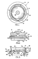
- Figure 1 is a plan view of a cover employing teachings of this invention.
- Figure 2 is a front elevational view of the cover of Fig. 1.
- Figure 3 is a transverse sectional view taken on line 3-3 of Fig. 2.
- Figure 4 is a perspective exploded view of a diluent container employing teachings of this invention.
- Figure 5 is a partial sectional view of the closure of the container of Fig. 4 in a normal position of assembly, i.e., with the cover in fluid sealing engagement with the port.
- Figure 6 is a view similar to Fig. 5 illustrating an altered configuration of the closure upon being subjected to a pressure environment exterior of the container which is less than the pressure within the container, such as is experienced during the cool-down cycle of sterilization in an autoclave.
- Figure 7 is a view similar to Figs. 5 and 6 illustrating an altered condition of the closure as a result of being subjected to a pressure environment exterior of the container which is greater than the pressure within the container, such as is also experienced in the course of sterilization in an autoclave.
- Figure 8 is an elevational view partly in section of the container of Fig. 5 in the course of having the frangible portion of the cover torn pursuant to removal of the central portion of the cover.
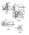
- Figure 9 is an enlarged fragmentary sectional view illustrating the frangible seal in a modified cover member employing teachings of this invention, and its attachment to a port to be sealed thereby.
- Figure 10 is a transverse sectional view partly in elevation illustrating a medicament vial in engagement with a diluent container after the cover of the diluent container port has been removed and before the inner port closure and vial stopper have been removed.
- Figure 11 is a partial sectional view of a modified closure assembly in which the pressure responsive, expansible diaphragm is formed with concentric corrugations.
- Figure 12 is a partial perspective view of the cover illustrated in Figure 9.
- Figure 13 is a partial top view of the force-concentrating post portion of the cover illustrated in Figure 9.
- Figure 14 is a sectional view taken generally along line 14-14 of Figure 5.
- Figure 15 is a sectional view similar to Figure 14 taken generally along line 15-15 of Figure 9.
- Referring now more particularly to Fig. 4, a
flexible container 8 includes a flexible bag 12, avial port 20 with acover member 10 and an administration port 100. The cover is attached to the port as in Figs. 5-7 during autoclaving, shipping and handling of the container. Theport 20 is designed to receive and engage a medicament vial as illustrated in Fig. 10, upon removal of the central portion of the cover 10 (see Fig. 8), for addition of a selected medicament to a diluent 18 in the bag. The administration port 100 may be of conventional design such as for filling of the bag, addition of other additives, or attachment of an I.V. tube or other extraction means. - The flexible container 12 is formed from two
sheets 14 of flexible plastic material which are sealed along their edge portions at 16. The diluent 18 may thus be contained without leakage between theopposed walls 14 of the container 12. Theport 20 defines a passageway therethrough for interconnecting the interior of the bag 12 with the exterior and is in fluid-tight engagement through anedge opening 22 by means ofmandrel seal 24. - The
port 20 is a generally tubular, hollow, relatively rigid member preferably formed of a temperature-stable material, such as a polyester resin which is substantially unaffected by temperature changes encountered in the course of autoclaving for sterilization purposes. This will assure maintenance of the configuration and dimensional tolerances of the port for mating reception of a vial and to maintain theinner seal closure 38 referred to below. Theport 20 has anopening 28 exteriorly disposed of the bag 12. Anannular flange 55 circumscribes theopen end 28, and a cover support wall or "fence" 70 extends outwardly therefrom, as discussed further below. As is more apparent from Figs. 5 through 8 of the drawing, thebody portion 30, which is concentric with theouter opening 28, hasthreads 32 formed on its inner periphery. Theportion 30 terminates in a distalcylindrical portion 34 having an annular bead orridge 36 integrally formed therewith. The latter ridge has a larger outer diameter than thecylindrical portion 34. - As is also illustrated in Figs. 5 through 8, a closure or
cap 38 for the inner end ofport 20 has an inwardly projectinglip 40 which engagesannular ridge 36 of theterminal portion 34 in a snap-fit engagement. A fluid-tight sealing engagement is maintained between thecap 38 and the terminus of theport 20 by means of a compressible and deformable O-ring 42 which is compressed in fluid-sealing engagement between the opposed surfaces comprising the innerperipheral surface 46 of theportion 34 and an opposingcylindrical surface 48 on the center portion ofcap 38. - The
cover member 10 typically is applied to the container prior to sterilization. It effects a desired fluid-tight seal closure over the outer end ofport 20 to prevent contamination and maintain sterility within the port from the time of sterilization until the container is being prepared for use. That preparation typically is done by a health care person, usually at bedside. Thecover 10 also will prevent loss of any liquid contents throughport 28 in the event of leakage or inadvertent removal ofclosure 38. Thecover member 10 may be formed of known flexible polyvinyl chloride compositions having inert fillers as known in the trade for purposes of providing a desired ease of tearing of a frangible seal contained therein. - Referring now more particularly to Figs. 1 through 3, the
cover member 10 comprises aperipheral flange 50 which has aplanar undersurface 52. Thesurface 52 is adapted to be secured to the upper surface of theannular flange 55 onport 20, see Figs. 4-8. A fluid-tight seal between thesurface 52 and upper surface offlange 55 may be effected by heat of sonic welding between the engaged surfaces. Any means for effecting a desired fluid-tight seal between the two annular surfaces may of course be employed. - As is most clearly seen from Fig. 3 of the drawing the inner edge of the
flange 50 is integrally formed with anannular bead 54 which defines the juncture between theflange 50 and a verticalcylindrical wall portion 56, see Fig. 2. A thin portion or section of the cover, at 58, between twosharp corners 58a and 58b, defines a tear line around the cover and which thus forms a readily frangible continuous membrane at the juncture betweenbead 54 andwall 56 which maintains the fluid-tight integrity of the cover. - The
wall 56 is joined at its upper end to the outer periphery of anannular portion 59 of adiaphragm section 67, see Figs. 1, 3 and 4. The latter annulus is concentric withflange 50 andbead 54. Integral with and depending from the inner peripheral edge ofannulus 59 is adiaphragm 57 comprising a depending,cylindrical wall portion 60 which has an outercylindrical surface 61 more clearly seen in Fig. 2. The bottom end ofwall 60 is continuous by means of a reverse bend or convolution with a dome-shapeddiaphragm portion 62. Thewall portion 60 anddome portion 62 define a flexible diaphragm which serves to complete the fluid-tight closure cross section spanning theannular flange 50. Centerhollow element 64 of diaphragm 57 (Fig. 3) is of a configuration dictated by the specific mold elements employed in the course of injection molding of thecover 10, and thus may be varied from the configuration illustrated, or omitted as desired, subject to maintaining the integrity of the cover. - The
dome 62 andwall 60 of theclosure 10 comprises an expansible bellows-type diaphragm 57 in that it will bend or roll at the wall convolutions and thus vary its configuration by flexing to vary the enclosed space to readily vary the enclosed volume within the port, as seen in Figs. 5-7. Thereby thediaphram 57 will minimize the pressure differential between the interior of the port and the ambient atmosphere when the assembly is in an autoclave for sterilization purposes. This minimizes the forces generated within the cover member and minimizes rupture and removal forces on thetear line 58 and removal forces on thecap 38. The above referred variances of the enclosed space and enclosed volume within the port also allow for a captured sterile volume of air within the port. This captured volume reduces or eliminates the inrush of air upon opening of the closure and correspondingly reduces the risk of contamination. - The
cover 10 typically is applied to flange 55 of thecontainer port 20 during manufacture of thecontainer 8. The diluent is added to the bag through port 100. The filled and sealedcontainer assembly 8 is then placed in an autoclave for sterilization purposes. In the process of sterilization, an autoclave pressure is generated which is in excess of the pressure within the interior of the container 12 and withinport 20. As a result, thediaphragm dome 62 is forced toward the interior of the container 12 generally in the manner illustrated in Fig. 7. As indicated in Fig. 7, thediaphragm dome 62 is flexed inwardly of the container and the outer diaphragm wall is bent or rolled inwardly of the container. - The ambient pressure in the autoclave in the later portion of the high temperature "peak dwell" period is less than that of the port interior, resulting in a pressure differential which forces the
closure diaphragm 62 upwardly away from the bag interior generally in the manner of Fig. 6.Walls - As noted above, a stress relief wall or "fence" 70 is provided on the port, see Fig. 4. This fence comprises a distal end wall portion of
port 20. It interfits within theannular channel 72 defined bysurface 61 ofwall 60 andinner surface 65 ofcylindrical wall 56 of thecover 10, see Figs. 3 and 5 - 8.Fence 70 is closely adjacent to thewall 56 and it is believed that thefence 70 and the related configuration of thecover 10 function to at least partially isolatetear line 58 from inwardly directed tensile forces generated in the cover, thereby protectingtear line 59 from unintentionally rupturing or tearing. Such forces may be generated in the cover member due to relative shrinkage or expansion of the closure components, or distortions within one or both components, as well as due to pressure differentials such as occur during autoclaving. In particular, if a shrinkable material such as PVC is used to form the cover and the port is dimensionally stable, e.g., formed of a polyester, the relative shrinkage factor and attendant forces may be significant. Those forces of course are in addition to the forces due to pressure differentials across the cover. It appears that abuttment of thewall 56 with thefence 70 at least contributes to the stress relief function. In that regard, the respective parts may be of designs and such relative dimensions that the annular wall of the cover abuts the fence upon initial assembly. However, it has been found in a current commercial embodiment that an initial radial spacing of about 0.050ʺ between thecover wall 56 and thefence 70, as illustrated in Fig. 14, functions satisfactorily. In that commercial embodiment, the port is molded of polyester with afence wall 70 of about 1.30ʺ outside diameter and about 0.13ʺ height aboveflange 5. The cover is molded of plasticized PVC with inert fillers as previously discussed, andwall 56 is about 0.02ʺ thick and extends axially about 0.06ʺ over the upper portion offence 70. In actual use, the shrinkage and other tensile forces apparently bend and otherwise distort thewall 56 such that at least upper portions thereof contact thefence 70 and are supported by the fence as tension forces generated within or applied to the center portions of the cover pull inwardly on that upper portion. - The
fence 70 is illustrated as an annular wall which presents a continuous annular outer support surface or of surfaces to thecover wall 56. However, it is believed that this fence also could be a series of spaced support sections, posts or rings provided that it is of sufficient height, and the open spaces sufficiently small, as to substantially prevent the cover from being pulled radially inward at the tear line. - It is therefore seen that the restraining
fence 70 of theport 20 and the related portions of the cover function as a stress relief for the tear line of theflexible cover 10. Further the diaphragm design enables differentials in pressure between the interior of theport 20 and an autoclave ambient atmosphere to be minimized without deleterious consequences to thefrangible seal 54 of the closure. - As above noted, the
container 8 is designed for intermixing into thediluent contents 18 thereof a medicament which is added by way of a vial which interconnects withport 20. Prior to such interconnection the center section of the cover is removed by tearing the cover alongtear line 58 to expose the port. This removal is effected by pulling on apull ring 76 in the manner of Fig. 8. - The
pull ring 76 is molded integrally with theannulus 59, being attached thereto by means of a narrow force-concentratingpost 82. The latter is most clearly seen in Figs 2 and 4. The ring also is temporarily attached to theannulus 59 by thin breakableintegral stringers 80 for purposes of holding the ring in position on the cover during manufacture, assembly and handling. Upon engagingpull ring 76 at the enlarged finger-locatingtab 78 and pulling in an upwardly direction so as to pullclosure wall portion 56 relative to bead 54, thethin stringers 80 are readily broken. The leading edges of the side stringers, toward thetab 78, are arcuate at their merger into the ring as seen in Figures 4-7 and 10 to prevent inadvertent tearing of the ring at those points when breaking the stringers. When thering 76 is pulled upwardly, generally as shown in Figure 8, thepost 82 causes the user's pulling force to be concentrated in a narrow area of thewall 56 and to be applied to a short length of thetear line 58. A narrow thickened portion ofwall 56, seen at 83 in Figures 3 and 14, effectively forms an extension of thepost 82 to assist in this force concentration. The frangible membrane is thus readily burst or broken to initiate a tearing action which then proceeds progressively along the tear line in each direction in the manner illustrated in Fig. 8. The entire diaphragm and remaining cover portion integrally formed therewith within the circle of the tear line thus may be readily torn free and detached from thecover portions sleeve flange 55. Upon such removal the inrush of air will be minimized, based upon the configuration and manner of removal of the center portion of the cover, whereby contamination is minimized. The initial oversize ofwall 56 relative to the periphery of thefence 70 and the attendant initial radial spacing therebetween insure that thewall 56 will be easily removable from the fence despite shrinkage of the wall during sterilization. - The
sleeve port 28 is then completely exposed and open for insertion of a vial of medicament such asvial 88 illustrated in Fig. 10. Male threads 90 disposed aboutneck 93 ofvial 88 threadably engage thefemale threads 32 formed on the interior of thecylindrical portion 30 ofsleeve 20. Ratchetteeth 89a on the vial enclosure also engagecomplementary teeth 89b on the port to preclude removal of the vial once engagement is initiated. In the course of connecting thevial 88 into thepost 20, a projecting arrow or prong-shapedhead 97 integrally formed withclosure cap 38 will pass into arecess 92 of vial stopper 94 such that theannular shoulder 96 of thehead 97 will engage behind anannular ledge 98 of stopper 94. Projectingribs 99 formed on the outer surface ofsleeve portion 30 reinforce that portion. Anannular sealing lip 101 on the port abuts the end finish of the vial to provide a sealed connection between the port and the neck of the sealed vial. - The
contents 89 ofvial 88 are released into thecontainer 8 by removing thecap 38 from engagement with theterminal bead 36 of theport 20. Manual disengagement of the cap from the port end is readily effected by manipulation of the cap by the user through theflexible container walls 14. Simultaneously with the cap removal, the stopper 94 of thevial 88 will be removed as a result of its interlocking engagement with theprojection 97 on thecap 38. - Following stopper and cap removal the
medicament 89 contained in thevial 88 will pour into the diluent 18. The flexible container 12 may be appropriately manipulated to ensure desired and complete mixing of the medicament within the diluent. The medicament may be any of a variety of powdered or liquid pharmaceutical products, vitamins or nutritional preparations to form the desired mixture with the diluent. The resulting desired mixture may then be dispensed through administration port 100 having acap closure 102. (See Fig. 4). - Although the
cover 10 employs adiaphragm 57 having adome 62 and reverse-folded flexible side walls, it will be apparent that the diaphragm portion which is able to telescopically react to pressure differentials may vary as incover 110 of Figure 11. In the embodiment of Figure 11, parts are identified by numbers in the 100 series corresponding to the numbers assigned to corresponding parts in the embodiment described above. Cover 110 has adiaphragm portion 167 comprising a concentric arrangement of contiguous convolutions or corrugations of alternate convex and concave configuration. Thediaphragm 167 can expand in either direction axially of theport 20 by flexing when exposed to pressure differentials. Cover 110 has acylindrical wall portion 156, having an inner surface which is snugly received around a supportingport wall 70 which functions as a strain relief as previously described in connection withclosure 10. Inclosure 110 anannular notch 118 defines a thinfrangible tear line 158 betweenattachment flange 150 andcylindrical wall 156. - Figures 9, 12, 13 and 15 illustrate another embodiment of the invention. In the embodiment of these Figures, parts are identified by numbers in the 200 series corresponding to the numbers assigned to corresponding parts in the embodiments described above. The embodiment of Figures 9, 12, 13 and 15 includes a modified
frangible tear line 258 which is elevated from theattachment flange 250 and disposed adjacent to the upper surface of and essentially coplanar with the base of theforce concentration post 282. The tear line thus passes closely adjacent to the base of thepost 282 such that the pull force applied through the post has little opportunity to spread through intervening materials and thus is more highly concentrated than in the embodiment of Figures 1-8. Thepost 282 also is V-shaped in cross-section, as best seen in Figures 12 and 13, with the point over thetear line 258 to even more narrowly or precisely focus the initial bursting force on the tear line when the user pulls onring 276. An inner reinforcing rib 283 overlaps the back side ofpost 282 and the upper portion ofwall 260. As illustrated in Figure 15wall 256 of this embodiment also is contiguous to thefence 70, as in the embodiment of Figure 9. - It is thus seen that a novel closure has been provided which meets the aforestated requirements and objects.
- The foregoing has made apparent a number of equivalent embodiments of the inventive features above described in detail. Accordingly, it is intended that the scope of this invention be limited only by the scope of the following claims.
Claims (31)
a port structure which defines an access opening through said wall; and
a thin flexible fluid-tight cover member over said opening;
said port structure including a support portion extending outwardly from said container and defining external support surfaces circumjacent said opening;
said cover member comprising a first portion extending across the outward end of said support portion and including a diaphragm section exposed to said opening, a second portion integral with said first portion and disposed circumjacent said external support surfaces, a third portion affixed to said port structure, and a frangible portion defining a tear line between said second portion and said third portion, whereby said second portion may engage said support portion for stress-relief protection of the integrity of said tear line from stresses in said first and second portions of said cover, and severance of said tear line permits removal of a section of said cover including said first and second portions to uncover said access opening.
a port structure which defines an access opening through said wall; and
a thin flexible fluid-tight cover member over said opening;
said port structure including a support portion extending outwardly from said container and defining external support surfaces circumjacent said opening;
said cover member comprising a first portion extending across the outward end of said support portion and including an expansible diaphragm section exposed to said opening, said diaphragm section including at least one annular convolution whereby said diaphragm section is expandable by flexing of said convolution to permit telescopic movement of the portion of said cover within said convolution inwardly and outwardly relative to said port structure, a second portion integral with said first portion and including a wall section disposed circumjacent said external support surfaces, a third portion affixed to said port structure, and a frangible portion defining a tear line between said second portion and said third portion, whereby said second portion may engage said support portion for stress-relief protection of the integrity of said tear line from stresses in said first and second portions of said cover, said first portion and said second portion constituting a removable section which is severable from the remainder of said cover by tearing along said tear line, a narrow post element integral with said removable section of said cover in an area adjacent said wall section for transmitting rupture forces to a limited segment of said tear line, and means for manually applying pulling force to said post for rupturing said tear line and subsequent removal of said removable section of said cover to uncover said access opening.
Priority Applications (1)
| Application Number | Priority Date | Filing Date | Title |
|---|---|---|---|
| AT86115044T ATE83916T1 (en) | 1985-12-09 | 1986-10-30 | CONTAINER AND CLOSING DEVICE. |
Applications Claiming Priority (2)
| Application Number | Priority Date | Filing Date | Title |
|---|---|---|---|
| US06/806,782 US4757911A (en) | 1985-12-09 | 1985-12-09 | Container and closure construction |
| US806782 | 1985-12-09 |
Publications (3)
| Publication Number | Publication Date |
|---|---|
| EP0225468A2 true EP0225468A2 (en) | 1987-06-16 |
| EP0225468A3 EP0225468A3 (en) | 1988-10-05 |
| EP0225468B1 EP0225468B1 (en) | 1992-12-30 |
Family
ID=25194829
Family Applications (1)
| Application Number | Title | Priority Date | Filing Date |
|---|---|---|---|
| EP19860115044 Expired - Lifetime EP0225468B1 (en) | 1985-12-09 | 1986-10-30 | Container and closure construction |
Country Status (15)
| Country | Link |
|---|---|
| US (1) | US4757911A (en) |
| EP (1) | EP0225468B1 (en) |
| JP (1) | JP2578592B2 (en) |
| KR (1) | KR950010675B1 (en) |
| AT (1) | ATE83916T1 (en) |
| AU (1) | AU602318B2 (en) |
| CA (1) | CA1268143A (en) |
| DE (1) | DE3687410T2 (en) |
| DK (1) | DK591486A (en) |
| ES (1) | ES2003589A6 (en) |
| GR (1) | GR862658B (en) |
| IE (1) | IE59592B1 (en) |
| IL (1) | IL80321A (en) |
| NZ (1) | NZ218161A (en) |
| ZA (1) | ZA867825B (en) |
Cited By (4)
| Publication number | Priority date | Publication date | Assignee | Title |
|---|---|---|---|---|
| EP0322713A2 (en) * | 1987-12-28 | 1989-07-05 | Abbott Laboratories | Container with improved ratchet teeth interlock |
| EP0529595A1 (en) * | 1991-08-29 | 1993-03-03 | Nissho Corporation | Drug container and dual container system for fluid therapy employing the same |
| US5342346A (en) * | 1992-04-10 | 1994-08-30 | Nissho Corporation | Fluid container |
| ES2562333R1 (en) * | 2013-05-29 | 2016-11-10 | Aptargroup, Inc., | CLOSURE WITH LID AND REMOVABLE MEMBRANE |
Families Citing this family (43)
| Publication number | Priority date | Publication date | Assignee | Title |
|---|---|---|---|---|
| US4898209A (en) * | 1988-09-27 | 1990-02-06 | Baxter International Inc. | Sliding reconstitution device with seal |
| US5004110A (en) * | 1989-08-03 | 1991-04-02 | Abbott Laboratories | Retortable closure for plastic container |
| JPH05103819A (en) * | 1991-08-08 | 1993-04-27 | Nissho Corp | Medicine receiving container |
| FR2682088B1 (en) * | 1991-10-04 | 1994-06-10 | Emballages Conditionnement | PACKAGING FOR THE EXTEMPORANEOUS PREPARATION OF MEDICINAL PRODUCTS. |
| JPH05137773A (en) * | 1991-11-15 | 1993-06-01 | Nissho Corp | Liquid chemical container |
| US5332399A (en) * | 1991-12-20 | 1994-07-26 | Abbott Laboratories | Safety packaging improvements |
| JPH05317383A (en) * | 1992-05-19 | 1993-12-03 | Nissho Corp | Solution container equipped with means for communicating with chemical container |
| JPH06239352A (en) * | 1993-02-05 | 1994-08-30 | Nissho Corp | Solution injection set |
| DE4410790A1 (en) * | 1994-03-28 | 1995-10-05 | Berg Jacob Gmbh Co Kg | Screw cap with welding ring |
| DE69632524T2 (en) * | 1995-01-30 | 2005-05-12 | Portola Packaging, Inc., San Jose | OUTLET DEVICE WITH REMOVABLE MEMBRANE |
| US6464096B2 (en) | 1995-01-30 | 2002-10-15 | Portola Packaging, Inc. | Fitment having removable membrane |
| US5909845A (en) * | 1996-06-28 | 1999-06-08 | S. C. Johnson & Son, Inc. | Wick-based liquid emanation system with child-resistant overcap |
| SE9702636D0 (en) * | 1997-07-08 | 1997-07-08 | Pharmacia & Upjohn Ab | Improvements related to medical containers |
| US6019750A (en) | 1997-12-04 | 2000-02-01 | Baxter International Inc. | Sliding reconstitution device with seal |
| GB9815291D0 (en) * | 1998-07-14 | 1998-09-09 | Nycomed Imaging As | Package |
| US7425209B2 (en) | 1998-09-15 | 2008-09-16 | Baxter International Inc. | Sliding reconstitution device for a diluent container |
| US6113583A (en) | 1998-09-15 | 2000-09-05 | Baxter International Inc. | Vial connecting device for a sliding reconstitution device for a diluent container |
| AR021220A1 (en) | 1998-09-15 | 2002-07-03 | Baxter Int | CONNECTION DEVICE FOR ESTABLISHING A FLUID COMMUNICATION BETWEEN A FIRST CONTAINER AND A SECOND CONTAINER. |
| US6367047B1 (en) | 1998-10-20 | 2002-04-02 | Ecrix | Multi-level error detection and correction technique for data storage recording device |
| US6381706B1 (en) | 1998-10-20 | 2002-04-30 | Ecrix Corporation | Fine granularity rewrite method and apparatus for data storage device |
| US6246551B1 (en) | 1998-10-20 | 2001-06-12 | Ecrix Corporation | Overscan helical scan head for non-tracking tape subsystems reading at up to 1X speed and methods for simulation of same |
| US6367048B1 (en) | 1998-11-16 | 2002-04-02 | Mcauliffe Richard | Method and apparatus for logically rejecting previously recorded track residue from magnetic media |
| US6421805B1 (en) | 1998-11-16 | 2002-07-16 | Exabyte Corporation | Rogue packet detection and correction method for data storage device |
| US20040118801A1 (en) * | 2002-10-30 | 2004-06-24 | Brown Craig E. | Fully vented wide rim nursing bottle |
| NZ522281A (en) * | 2000-05-08 | 2005-07-29 | New Vent Designs Inc | Fully vented wide rim nursing bottle |
| US7828165B2 (en) * | 2000-05-08 | 2010-11-09 | New Vent Designs, Inc | Fully vented wide rim nursing bottle with contoured vent tube |
| US20050258124A1 (en) * | 2002-10-30 | 2005-11-24 | Brown Craig E | Fully vented wide rim nursing bottle with contoured vent tube |
| KR100535744B1 (en) * | 2002-03-07 | 2006-01-10 | 넥솔테크(주) | A Sealed Container for Liquid Foods Extraction |
| US6994699B2 (en) * | 2002-06-12 | 2006-02-07 | Baxter International Inc. | Port, a container and a method for accessing a port |
| US7413097B1 (en) | 2003-08-01 | 2008-08-19 | Portola Packaging, Inc. | Tamper-evident closure and method of making same |
| US7641851B2 (en) | 2003-12-23 | 2010-01-05 | Baxter International Inc. | Method and apparatus for validation of sterilization process |
| US20060111688A1 (en) * | 2004-11-22 | 2006-05-25 | Kraus Robert G | Ventriculostomy reservoir |
| AU2005322136B2 (en) * | 2004-12-23 | 2011-01-06 | Hospira, Inc. | Port closure system for intravenous fluid container |
| US7488311B2 (en) | 2004-12-23 | 2009-02-10 | Hospira, Inc. | Port closure system for intravenous fluid container |
| KR100899485B1 (en) * | 2005-06-14 | 2009-05-26 | 뉴 벤트 디자인스, 인크 | Nursing bottle assembly |
| US8757406B2 (en) * | 2005-10-26 | 2014-06-24 | New Vent Designs, Inc. | Fully vented wide rim nursing bottle |
| US8216207B2 (en) | 2007-08-01 | 2012-07-10 | Hospira, Inc. | Medicament admixing system |
| US8146759B2 (en) * | 2009-01-21 | 2012-04-03 | New Vent Designs, Inc. | Fully vented wide rim nursing bottle with canted vent tube |
| US8721612B2 (en) | 2010-12-17 | 2014-05-13 | Hospira, Inc. | System and method for intermixing the contents of two containers |
| CA2848825A1 (en) | 2011-10-03 | 2013-04-18 | Hospira, Inc. | System and method for mixing the contents of two containers |
| GB2525802B (en) | 2013-05-29 | 2020-11-25 | Aptargroup Inc | Closure with lid and removable membrane |
| US11059633B2 (en) | 2019-10-31 | 2021-07-13 | Cheer Pack North America | Flip-top closure for container |
| KR20220163363A (en) * | 2020-02-13 | 2022-12-09 | 웨스트 파마수티컬 서비시즈, 인코포레이티드 | Containment and delivery systems for cryogenic storage |
Citations (6)
| Publication number | Priority date | Publication date | Assignee | Title |
|---|---|---|---|---|
| US4344472A (en) * | 1981-04-13 | 1982-08-17 | Abbott Laboratories | Pull tab tear cap for container port |
| EP0117489A2 (en) * | 1983-02-28 | 1984-09-05 | Abbott Laboratories | Dual compartmented container |
| US4523691A (en) * | 1983-04-08 | 1985-06-18 | Abbott Laboratories | Port structure for I.V. container |
| EP0155560A2 (en) * | 1984-03-19 | 1985-09-25 | Abbott Laboratories | Drug delivery system |
| US4601704A (en) * | 1983-10-27 | 1986-07-22 | Abbott Laboratories | Container mixing system with externally mounted drug container |
| US4606734A (en) * | 1984-02-22 | 1986-08-19 | Abbott Laboratories | Container mixing system with externally mounted drug container |
Family Cites Families (24)
| Publication number | Priority date | Publication date | Assignee | Title |
|---|---|---|---|---|
| US2034739A (en) * | 1931-06-18 | 1936-03-24 | Lydia B Koch | Paper cap for bottles |
| US2040798A (en) * | 1934-06-05 | 1936-05-12 | Schoonmaker Carl | Telltale closure device |
| US2723041A (en) * | 1951-04-09 | 1955-11-08 | Hart-Still Sydney Charles | Closure for bottles and other containers |
| US3047178A (en) * | 1958-06-24 | 1962-07-31 | Baxter Laboratories Inc | Closure system |
| US3434620A (en) * | 1966-03-10 | 1969-03-25 | American Flange & Mfg | Frangible plastic closure |
| US3394831A (en) * | 1966-06-13 | 1968-07-30 | American Hospital Supply Corp | Apparatus for storing and handling parenteral liquids and method for opening same |
| US3465910A (en) * | 1967-10-02 | 1969-09-09 | Owens Illinois Inc | Container closure having integral strip opening means |
| US3509879A (en) * | 1967-11-24 | 1970-05-05 | American Hospital Supply Corp | Parenteral liquid container having frangible part structure |
| ZA72496B (en) * | 1971-03-03 | 1972-09-27 | Baxter Laboratories Inc | Tamperproof and reusable sterile closure assembly |
| US3981412A (en) * | 1971-03-29 | 1976-09-21 | Asmus Richard W | Container closure |
| US3923183A (en) * | 1973-03-07 | 1975-12-02 | American Hospital Supply Corp | Container for medical liquid with separable outer and inner closures |
| US3915212A (en) * | 1973-12-10 | 1975-10-28 | Abbott Lab | Flexible medical fluid container having a combined fill and administration port and reinforced hanger |
| NL7413077A (en) * | 1974-10-03 | 1976-04-06 | Leer Koninklijke Emballage | HOLDER WITH SCREW CAP. |
| US3940802A (en) * | 1975-01-24 | 1976-03-02 | The Green Cross Corporation | Medical appliance made of plastic |
| US3946891A (en) * | 1975-04-07 | 1976-03-30 | Picoy Anthony R | Safety cap for pressurized bottles |
| US3999678A (en) * | 1975-12-01 | 1976-12-28 | Sobrefina Sa | Closing arrangement for packing containers |
| US4187893A (en) * | 1978-07-19 | 1980-02-12 | Abbott Laboratories | Combined additive and administration port for a container |
| JPS5841964Y2 (en) * | 1979-05-18 | 1983-09-22 | テルモ株式会社 | plastic pharmaceutical liquid containers |
| US4303067A (en) * | 1980-01-21 | 1981-12-01 | American Hospital Supply Corporation | Medical liquid bag having an improved additive port |
| US4344545A (en) * | 1981-04-13 | 1982-08-17 | The Continental Group, Inc. | Pilferproof closure with mechanical interlock |
| JPS5886173A (en) * | 1981-11-16 | 1983-05-23 | 東洋製罐株式会社 | Gasket of container for blood transfusion and preparation thereof |
| US4442949A (en) * | 1983-03-21 | 1984-04-17 | American Flange & Manufacturing Co. Inc. | Tear open closure assembly |
| US4506807A (en) * | 1983-04-13 | 1985-03-26 | Anderson James Y | Powder dispensing container for dripless assembly to and disassembly from a flame spraying torch |
| AU581188B2 (en) * | 1983-11-17 | 1989-02-16 | Visy Industrial Plastics Pty Ltd | Closure means and parts thereof |
-
1985
- 1985-12-09 US US06/806,782 patent/US4757911A/en not_active Expired - Lifetime
-
1986
- 1986-10-15 ZA ZA867825A patent/ZA867825B/en unknown
- 1986-10-15 IL IL8032186A patent/IL80321A/en not_active IP Right Cessation
- 1986-10-30 AT AT86115044T patent/ATE83916T1/en not_active IP Right Cessation
- 1986-10-30 DE DE19863687410 patent/DE3687410T2/en not_active Expired - Fee Related
- 1986-10-30 EP EP19860115044 patent/EP0225468B1/en not_active Expired - Lifetime
- 1986-11-03 GR GR862658A patent/GR862658B/en unknown
- 1986-11-04 NZ NZ21816186A patent/NZ218161A/en unknown
- 1986-12-02 CA CA000524369A patent/CA1268143A/en not_active Expired - Lifetime
- 1986-12-03 AU AU66044/86A patent/AU602318B2/en not_active Ceased
- 1986-12-05 ES ES8603320A patent/ES2003589A6/en not_active Expired
- 1986-12-08 KR KR1019860010446A patent/KR950010675B1/en not_active IP Right Cessation
- 1986-12-08 IE IE321386A patent/IE59592B1/en not_active IP Right Cessation
- 1986-12-09 DK DK591486A patent/DK591486A/en not_active Application Discontinuation
- 1986-12-09 JP JP29169786A patent/JP2578592B2/en not_active Expired - Fee Related
Patent Citations (6)
| Publication number | Priority date | Publication date | Assignee | Title |
|---|---|---|---|---|
| US4344472A (en) * | 1981-04-13 | 1982-08-17 | Abbott Laboratories | Pull tab tear cap for container port |
| EP0117489A2 (en) * | 1983-02-28 | 1984-09-05 | Abbott Laboratories | Dual compartmented container |
| US4523691A (en) * | 1983-04-08 | 1985-06-18 | Abbott Laboratories | Port structure for I.V. container |
| US4601704A (en) * | 1983-10-27 | 1986-07-22 | Abbott Laboratories | Container mixing system with externally mounted drug container |
| US4606734A (en) * | 1984-02-22 | 1986-08-19 | Abbott Laboratories | Container mixing system with externally mounted drug container |
| EP0155560A2 (en) * | 1984-03-19 | 1985-09-25 | Abbott Laboratories | Drug delivery system |
Cited By (6)
| Publication number | Priority date | Publication date | Assignee | Title |
|---|---|---|---|---|
| EP0322713A2 (en) * | 1987-12-28 | 1989-07-05 | Abbott Laboratories | Container with improved ratchet teeth interlock |
| EP0322713A3 (en) * | 1987-12-28 | 1989-10-18 | Abbott Laboratories | Container with improved ratchet teeth interlock |
| EP0529595A1 (en) * | 1991-08-29 | 1993-03-03 | Nissho Corporation | Drug container and dual container system for fluid therapy employing the same |
| US5342347A (en) * | 1991-08-29 | 1994-08-30 | Nissho Corporation | Drug container and dual container system for fluid therapy employing the same |
| US5342346A (en) * | 1992-04-10 | 1994-08-30 | Nissho Corporation | Fluid container |
| ES2562333R1 (en) * | 2013-05-29 | 2016-11-10 | Aptargroup, Inc., | CLOSURE WITH LID AND REMOVABLE MEMBRANE |
Also Published As
| Publication number | Publication date |
|---|---|
| DK591486D0 (en) | 1986-12-09 |
| NZ218161A (en) | 1990-07-26 |
| IE863213L (en) | 1987-06-09 |
| ZA867825B (en) | 1988-03-30 |
| AU602318B2 (en) | 1990-10-11 |
| KR950010675B1 (en) | 1995-09-21 |
| JPS62137056A (en) | 1987-06-19 |
| DK591486A (en) | 1987-06-10 |
| ATE83916T1 (en) | 1993-01-15 |
| US4757911A (en) | 1988-07-19 |
| DE3687410D1 (en) | 1993-02-11 |
| CA1268143A (en) | 1990-04-24 |
| ES2003589A6 (en) | 1988-11-01 |
| GR862658B (en) | 1987-03-03 |
| AU6604486A (en) | 1987-06-11 |
| JP2578592B2 (en) | 1997-02-05 |
| EP0225468B1 (en) | 1992-12-30 |
| IL80321A0 (en) | 1987-01-30 |
| IL80321A (en) | 1991-12-12 |
| IE59592B1 (en) | 1994-03-09 |
| EP0225468A3 (en) | 1988-10-05 |
| DE3687410T2 (en) | 1993-05-27 |
| KR870005879A (en) | 1987-07-07 |
Similar Documents
| Publication | Publication Date | Title |
|---|---|---|
| EP0225468B1 (en) | Container and closure construction | |
| US4640424A (en) | Self-opening nipple construction and nursing container | |
| EP1063956B1 (en) | Improved adaptor cap | |
| US4449640A (en) | Tamper-resistant pharmaceutical vial and cap assembly | |
| US5114421A (en) | Medicament container/dispenser assembly | |
| US4420092A (en) | Tamper-resistant pharmaceutical vial and cap assembly | |
| CA1307432C (en) | Medical apparatus with tamper evident indicator means | |
| US4606734A (en) | Container mixing system with externally mounted drug container | |
| JPH02503272A (en) | A device that brings materials such as drugs into contact with liquids | |
| US5531695A (en) | Tamper evident sleeve | |
| US4614267A (en) | Dual compartmented container | |
| US7334702B2 (en) | Tamper resistant beverage dispensing bag | |
| EP0322713A2 (en) | Container with improved ratchet teeth interlock | |
| CA2076773C (en) | Drug container and dual container system for fluid therapy employing the same | |
| EP0528231A1 (en) | Drug vessel | |
| US3978859A (en) | Closure member for pierceable access ports | |
| US4586622A (en) | Tamper-resistant pharmaceutical vial and cap assembly | |
| US4240481A (en) | Seal for flexible container having flexible, generally conical portions | |
| IE48193B1 (en) | Closure cap for liquid container | |
| US4809871A (en) | Closure for sealing an aperture | |
| US4872872A (en) | Medicament container/dispenser assembly | |
| US4305443A (en) | Seal for flexible container having flexible, generally conical portions | |
| GB2043605A (en) | Closure having a breakaway cap | |
| US4143786A (en) | Additive cap and snap-on retention ring for medical liquid container | |
| EP0678042A1 (en) | A system for filling an anaesthetic vaporizer |
Legal Events
| Date | Code | Title | Description |
|---|---|---|---|
| PUAI | Public reference made under article 153(3) epc to a published international application that has entered the european phase |
Free format text: ORIGINAL CODE: 0009012 |
|
| AK | Designated contracting states |
Kind code of ref document: A2 Designated state(s): AT BE CH DE FR GB IT LI LU NL SE |
|
| PUAL | Search report despatched |
Free format text: ORIGINAL CODE: 0009013 |
|
| RHK1 | Main classification (correction) |
Ipc: A61J 1/00 |
|
| AK | Designated contracting states |
Kind code of ref document: A3 Designated state(s): AT BE CH DE FR GB IT LI LU NL SE |
|
| 17P | Request for examination filed |
Effective date: 19890325 |
|
| 17Q | First examination report despatched |
Effective date: 19900926 |
|
| GRAA | (expected) grant |
Free format text: ORIGINAL CODE: 0009210 |
|
| AK | Designated contracting states |
Kind code of ref document: B1 Designated state(s): AT BE CH DE FR GB IT LI LU NL SE |
|
| REF | Corresponds to: |
Ref document number: 83916 Country of ref document: AT Date of ref document: 19930115 Kind code of ref document: T |
|
| ET | Fr: translation filed | ||
| REF | Corresponds to: |
Ref document number: 3687410 Country of ref document: DE Date of ref document: 19930211 |
|
| ITF | It: translation for a ep patent filed |
Owner name: MODIANO & ASSOCIATI S.R.L. |
|
| PG25 | Lapsed in a contracting state [announced via postgrant information from national office to epo] |
Ref country code: GB Effective date: 19931030 Ref country code: AT Effective date: 19931030 |
|
| PG25 | Lapsed in a contracting state [announced via postgrant information from national office to epo] |
Ref country code: SE Effective date: 19931031 Ref country code: LU Free format text: LAPSE BECAUSE OF NON-PAYMENT OF DUE FEES Effective date: 19931031 Ref country code: LI Effective date: 19931031 Ref country code: CH Effective date: 19931031 Ref country code: BE Effective date: 19931031 |
|
| PLBE | No opposition filed within time limit |
Free format text: ORIGINAL CODE: 0009261 |
|
| STAA | Information on the status of an ep patent application or granted ep patent |
Free format text: STATUS: NO OPPOSITION FILED WITHIN TIME LIMIT |
|
| 26N | No opposition filed | ||
| BERE | Be: lapsed |
Owner name: ABBOTT LABORATORIES Effective date: 19931031 |
|
| PG25 | Lapsed in a contracting state [announced via postgrant information from national office to epo] |
Ref country code: NL Effective date: 19940501 |
|
| NLV4 | Nl: lapsed or anulled due to non-payment of the annual fee | ||
| GBPC | Gb: european patent ceased through non-payment of renewal fee |
Effective date: 19931030 |
|
| PG25 | Lapsed in a contracting state [announced via postgrant information from national office to epo] |
Ref country code: FR Effective date: 19940630 |
|
| REG | Reference to a national code |
Ref country code: CH Ref legal event code: PL |
|
| PG25 | Lapsed in a contracting state [announced via postgrant information from national office to epo] |
Ref country code: DE Effective date: 19940701 |
|
| REG | Reference to a national code |
Ref country code: FR Ref legal event code: ST |
|
| EUG | Se: european patent has lapsed |
Ref document number: 86115044.9 Effective date: 19940510 |
|
| PG25 | Lapsed in a contracting state [announced via postgrant information from national office to epo] |
Ref country code: IT Free format text: LAPSE BECAUSE OF NON-PAYMENT OF DUE FEES;WARNING: LAPSES OF ITALIAN PATENTS WITH EFFECTIVE DATE BEFORE 2007 MAY HAVE OCCURRED AT ANY TIME BEFORE 2007. THE CORRECT EFFECTIVE DATE MAY BE DIFFERENT FROM THE ONE RECORDED. Effective date: 20051030 |