EP0226397B1 - Disposable catheter insertion apparatus - Google Patents
Disposable catheter insertion apparatus Download PDFInfo
- Publication number
- EP0226397B1 EP0226397B1 EP86309448A EP86309448A EP0226397B1 EP 0226397 B1 EP0226397 B1 EP 0226397B1 EP 86309448 A EP86309448 A EP 86309448A EP 86309448 A EP86309448 A EP 86309448A EP 0226397 B1 EP0226397 B1 EP 0226397B1
- Authority
- EP
- European Patent Office
- Prior art keywords
- catheter
- introducer
- sheath
- tube
- blood vessel
- Prior art date
- Legal status (The legal status is an assumption and is not a legal conclusion. Google has not performed a legal analysis and makes no representation as to the accuracy of the status listed.)
- Expired - Lifetime
Links
- 238000003780 insertion Methods 0.000 title abstract description 12
- 230000037431 insertion Effects 0.000 title abstract description 12
- 210000004204 blood vessel Anatomy 0.000 claims description 24
- 210000004369 blood Anatomy 0.000 claims description 8
- 239000008280 blood Substances 0.000 claims description 8
- 230000036512 infertility Effects 0.000 claims description 4
- 230000001681 protective effect Effects 0.000 abstract description 3
- 239000004033 plastic Substances 0.000 description 6
- 229920003023 plastic Polymers 0.000 description 6
- 239000000463 material Substances 0.000 description 4
- 238000001802 infusion Methods 0.000 description 3
- 238000000034 method Methods 0.000 description 2
- 238000000465 moulding Methods 0.000 description 2
- 229910001220 stainless steel Inorganic materials 0.000 description 2
- 239000010935 stainless steel Substances 0.000 description 2
- 239000012780 transparent material Substances 0.000 description 2
- POIUWJQBRNEFGX-XAMSXPGMSA-N cathelicidin Chemical compound C([C@@H](C(=O)N[C@@H](CCCNC(N)=N)C(=O)N[C@@H](CCCCN)C(=O)N[C@@H](CO)C(=O)N[C@@H](CCCCN)C(=O)N[C@@H](CCC(O)=O)C(=O)N[C@@H](CCCCN)C(=O)N[C@@H]([C@@H](C)CC)C(=O)NCC(=O)N[C@@H](CCCCN)C(=O)N[C@@H](CCC(O)=O)C(=O)N[C@@H](CC=1C=CC=CC=1)C(=O)N[C@@H](CCCCN)C(=O)N[C@@H](CCCNC(N)=N)C(=O)N[C@@H]([C@@H](C)CC)C(=O)N[C@@H](C(C)C)C(=O)N[C@@H](CCC(N)=O)C(=O)N[C@@H](CCCNC(N)=N)C(=O)N[C@@H]([C@@H](C)CC)C(=O)N[C@@H](CCCCN)C(=O)N[C@@H](CC(O)=O)C(=O)N[C@@H](CC=1C=CC=CC=1)C(=O)N[C@@H](CC(C)C)C(=O)N[C@@H](CCCNC(N)=N)C(=O)N[C@@H](CC(N)=O)C(=O)N[C@@H](CC(C)C)C(=O)N[C@@H](C(C)C)C(=O)N1[C@@H](CCC1)C(=O)N[C@@H](CCCNC(N)=N)C(=O)N[C@@H]([C@@H](C)O)C(=O)N[C@@H](CCC(O)=O)C(=O)N[C@@H](CO)C(O)=O)NC(=O)[C@H](CC=1C=CC=CC=1)NC(=O)[C@H](CC(O)=O)NC(=O)CNC(=O)[C@H](CC(C)C)NC(=O)[C@@H](N)CC(C)C)C1=CC=CC=C1 POIUWJQBRNEFGX-XAMSXPGMSA-N 0.000 description 1
- 239000002131 composite material Substances 0.000 description 1
- 238000005336 cracking Methods 0.000 description 1
- 201000010099 disease Diseases 0.000 description 1
- 208000037265 diseases, disorders, signs and symptoms Diseases 0.000 description 1
- 208000015181 infectious disease Diseases 0.000 description 1
- 238000009434 installation Methods 0.000 description 1
- 238000001990 intravenous administration Methods 0.000 description 1
- 230000007774 longterm Effects 0.000 description 1
- 238000004519 manufacturing process Methods 0.000 description 1
- 239000000843 powder Substances 0.000 description 1
- 230000000717 retained effect Effects 0.000 description 1
- 230000007704 transition Effects 0.000 description 1
- 210000003462 vein Anatomy 0.000 description 1
Images

Classifications
-
- A—HUMAN NECESSITIES
- A61—MEDICAL OR VETERINARY SCIENCE; HYGIENE
- A61M—DEVICES FOR INTRODUCING MEDIA INTO, OR ONTO, THE BODY; DEVICES FOR TRANSDUCING BODY MEDIA OR FOR TAKING MEDIA FROM THE BODY; DEVICES FOR PRODUCING OR ENDING SLEEP OR STUPOR
- A61M25/00—Catheters; Hollow probes
- A61M25/01—Introducing, guiding, advancing, emplacing or holding catheters
- A61M25/06—Body-piercing guide needles or the like
- A61M25/0662—Guide tubes
- A61M25/0668—Guide tubes splittable, tear apart
Definitions
- the present invention relates to a disposable catheter insertion apparatus for inserting a catheter under sterile conditions into a blood vessel.
- Prior art devices for inserting a plastic catheter through a tubular needle into a blood vessel are known; one example is disclosed in Japanese laid open patent publication Sho 56-20023.
- the catheter is usually contained in a sealed casing or sheath for sterility and the sheath may be provided with an introducer to be attached to the proximal end of a cannula.
- a known introducer comprises a stainless steel tube in a plastics moulding.
- the stainless steel tube is necessary to reduce sliding resistance to a minimum so that the operator can sense actual resistance of the catheter in the blood vessel. If the sliding resistance is great there is a danger that the operator may unexpectedly force the catheter through the wall of the blood vessel; this occurence is not infrequent. There is an additional danger that plastic may be abraded and the resulting fine powder carried into the blood vessel by sticking to the catheter.
- This composite introducer is also difficult to manufacture.
- the introducer is usually non transparent and the catheter sheath is usually only semi-transparent; it is therefore difficult to determine the length of catheter inserted into the blood vessel.
- the catheter and an extension tube thereof are integrally constituted. It is often necessary to disconnect and reconnect infusion apparatus during long term placement of the catheter and this can lead to loose fitting and cracking of the proximal catheter connector with consequent loss of sterility and reliability. If the connector is damaged the catheter may have to be replaced.
- the length of catheter remaining outside the blood vessel may be considerable and the excess must be gathered into a loop which is generally inconvenient and awkward.
- the sheath for the catheter is often a plastic bag through which the catheter is gripped for insertion; the catheter must be held in the inserted condition whilst the bag is pulled back for a second insertion stroke and this is generally inconvenient and difficult.
- FR-A-2 522 507 discloses a catheter comprising a flexible tube in which may be inserted, at the time of placement into the vein, a rigid mandrel, which may subsequently be withdrawn by sliding it inside the tube, said catheter being characterised in that it comprises, on the proximal side, a stopper or connector fast with the mandrel, that the connector has an internal seat for receiving the end of a syringe and that an internal passage is incorporated in the connector, between the bottom of the seat and the proximal end of the mandrel, the assembly being such that a clear space is left at the proximal end of the mandrel, on the periphery of the latter.
- One object of the present invention is to provide a catheter insertion apparatus which overcomes the aforementioned problems and permits easy, sterile insertion of a catheter into a blood vessel to any desired depth.
- a catheter introducer assembly comprising a catheter, a sheath therefor and a cannula, whereby the tubular sheath is telescoped over said catheter and includes an introducer comprising a tubular member having a distal arm extending axially thereof, and a tube attached to said arm and extending proximally into said tubular member and being spaced from the inner wall thereof, said introducer being slidably telescoped on said catheter, for separating the sheath from said catheter responsive to movement of the catheter through said introducer and for inserting said catheter to a selected depth from within said sheath into a blood vessel while maintaining sterility of said catheter until said catheter enters the blood vessel, and the cannula has distal and proximal ends wherein said introducer attaches to the proximal end thereof and the distal end of said cannula can be inserted into a blood vessel to allow the catheter to pass from said introducer into the blood vessel said introducer having a side opening through which the sheath
- Such an introducer permits use of a catheter contained within a sheath whereby the distal end of the catheter is inserted into the tube and the distal end of the sheath is inserted into the tubular member around said tube.
- the introducer has a side opening and the sheath can be pulled through this opening thus urging the catheter through the introducer into the blood vessel.
- This arrangement permits a single continuous installation movement with the flexible sheath under tension; control of the catheter and sensing of resistance in the blood vessel is thereby improved.
- the tube and tubular member of the introducer are preferably co-axial and the introducer may incorporate a blood check valve in the tube.
- the introducer may be moulded in two substantially symmetrical parts which fit together about the catheter. Such an introducer can be removed after use by splitting.
- the invention also provides a catheter extension tube having a capilliary needle on one end thereof for insertion in a catheter, attachment wings proximal of the needle and a connector at the other end thereof.
- Such an extension tube permits use of a catheter without the usual proximal connector in which case a non-splittable introducer can be used.
- the extension tube can be replaced quickly and easily without disturbing the catheter if, for example, the proximal connector of the tube is damaged after repeated connection and disconnection of infusion apparatus.
- the sheath of the invention may have a continuous slit along the length thereof or may have a longitudinal line of weakness, for example a line of incompatible material, so long as the line of weakness permits free splitting of the sheath during the catheter insertion process.
- the introducer assembly described hereinafter is supplied in a sealed and sterilized container (not shown) and is removed therefrom immediately prior to use.
- an introducer 11 comprising two substantially symmetrical parts 12, 13 and having projections 14 and corresponding holes (not shown) to locate one part relative to the other.
- the introducer is moulded in a relatively hard plastic and may be transparent.
- the introducer defines a tube 15 having a tubular member or annular shield 16 around the proximal end thereof and finger grips 17.
- the shield 16 is connected to the mid-portion of the tube 15 by an axially extending arm, of generally "u" shaped section; the underside of the tube is connected to the arm at a part more proximal than the upper surface and the intermediate portion is moulded to provide smooth transition around the tube.
- the arrangement of tube and arm define an opening in the upper surface of the assembled introducer.
- the distal end of the tube has a luer taper, for engagement with a cannula, and is closed by a cap 18.
- a blood check valve 19 is disposed within the tube and retained in one half thereof as shown; the valve has a slit for removal from the catheter as will be described hereinafter.
- an introducer assembly including a sheath 21 of resilient transparent material and having a continuous slit along the length thereof; the slit is closed by the natural resiliency of the material.
- the material of the sheath is of sufficient resilience to prevent the slit opening when the sheath is bent.
- the sheath 21 is fitted at one end to the introducer around the proximal end of the tube 15 and within the shield 16.
- the distal end of the catheter is inserted into the tube 15.
- the proximal end of the catheter has an end fitting 23, which may have a female luer taper, and is closed by a cap 24.
- the proximal end of the sheath engages the fitting 23 as shown.
- a syringe 26 having a needle 27 and surrounding plastics cannula 28.
- a protective cap 29 is provided for the cannulated needle.
- the cannula is of translucent or preferably transparent material.
- the syringe and cannulated needle is taken out of the usual sterile pack and the cap 29 removed.
- the needle is inserted into the desired blood vessel and blood passes into the syringe confirming that the needle is correctly inserted.
- the cannula 28 is pushed off the tip of the syringe 26 into the blood vessel and the syringe 26 and needle 27 withdrawn for disposal.
- the introducer assembly which has previously been removed from its sterile pack, is attached to the funnel end of the cannula.
- the cannula is firmly held by one hand whilst the sheath is moved distally through the shield 16; this initial movement causes the catheter 22 to be advanced through the blood check valve 19 and cannula 28 into the blood vessel.
- the sheath slit opens around the tube 15 and the distal end of the sheath emerges through the side aperture of the introducer as shown in Figure 4. Further distal movement of the catheter 22 can be accomplished by pulling the free end of the sheath 21; this gives smooth uninterrupted movement of the catheter into the blood vessel; the sheath is maintained under tension giving greater control and feel to the user.
- the catheter graduations indicate when the desired depth of insertion is reached.
- the user then removes the remainder of the sheath and separates the introducer and cannula.
- the introducer is split into the two parts for disposal and the blood check valve removed from the catheter.
- the cannula is removed from the blood vessel and may be splittable in any known manner for removal from the catheter and disposal; for example the cannula may have a longitudinally extending line of incompatible material.
- the proximal end of the catheter is attached to other medical apparatus, for example an intravenous drip, in the usual way.
- Figure 4 illustrates a catheter without a proximal connector, the sheath 21 is closed at the proximal end thereof to provide a sterile environment for the catheter.
- the excess distal portion may be cut off and the winged extension tube 31 of Figure 5 inserted after the protective cover 32 is first removed.
- the extension tube 31 has at one end a capilliary extension 34 for connection to the catheter, and at the other end a female connector 35 closed by a removable plug 36 which may be removed for connection of the tube 31 to external apparatus.
- the wings 33 may be attached to the patient's skin by tape or by sutures through the holes shown.
- the extension tube 31 has a sleeve 37 at the proximal end thereof to permit the tube to be gripped by forceps without damage thereto.
- a one-piece introducer moulding is permissible.
- the extension tube 31 can be firmly fixed to the patient's skin without stressing the catheter and can be removed and replaced easily should the female connector become damaged through repeated connection and disconnection of infusion apparatus.
- the catheter 22 can remain undisturbed in the patient whilst the extension tube is replaced.
- the cannula, introducer and sheath are preferably transparent so that the user can visualise the depth markings on the catheter.
Landscapes
- Health & Medical Sciences (AREA)
- Life Sciences & Earth Sciences (AREA)
- Hematology (AREA)
- Public Health (AREA)
- Engineering & Computer Science (AREA)
- Anesthesiology (AREA)
- Biomedical Technology (AREA)
- Heart & Thoracic Surgery (AREA)
- Biophysics (AREA)
- Animal Behavior & Ethology (AREA)
- General Health & Medical Sciences (AREA)
- Pulmonology (AREA)
- Veterinary Medicine (AREA)
- Media Introduction/Drainage Providing Device (AREA)
- Absorbent Articles And Supports Therefor (AREA)
- Infusion, Injection, And Reservoir Apparatuses (AREA)
- External Artificial Organs (AREA)
- Materials For Medical Uses (AREA)
- Ultra Sonic Daignosis Equipment (AREA)
Abstract
Description
- The present invention relates to a disposable catheter insertion apparatus for inserting a catheter under sterile conditions into a blood vessel.
- Prior art devices for inserting a plastic catheter through a tubular needle into a blood vessel are known; one example is disclosed in Japanese laid open patent publication Sho 56-20023. The catheter is usually contained in a sealed casing or sheath for sterility and the sheath may be provided with an introducer to be attached to the proximal end of a cannula.
- The applicants are aware of the following disadvantages with prior art devices.
- After insertion of the catheter into the blood vessel it is usually impossible to remove the introducer and cannula from the end of the catheter because of the proximal connector thereon. One solution is to attach these blood stained components to the proximal connector but this is unsightly and dangerous and may moreover cause infection and disease. Furthermore, the blood stained introducer and cannula are a hinderance in securing the catheter to the skin.
- A known introducer comprises a stainless steel tube in a plastics moulding. The stainless steel tube is necessary to reduce sliding resistance to a minimum so that the operator can sense actual resistance of the catheter in the blood vessel. If the sliding resistance is great there is a danger that the operator may unexpectedly force the catheter through the wall of the blood vessel; this occurence is not infrequent. There is an additional danger that plastic may be abraded and the resulting fine powder carried into the blood vessel by sticking to the catheter. This composite introducer is also difficult to manufacture.
- The introducer is usually non transparent and the catheter sheath is usually only semi-transparent; it is therefore difficult to determine the length of catheter inserted into the blood vessel.
- The catheter and an extension tube thereof are integrally constituted. It is often necessary to disconnect and reconnect infusion apparatus during long term placement of the catheter and this can lead to loose fitting and cracking of the proximal catheter connector with consequent loss of sterility and reliability. If the connector is damaged the catheter may have to be replaced.
- The length of catheter remaining outside the blood vessel may be considerable and the excess must be gathered into a loop which is generally inconvenient and awkward.
- The sheath for the catheter is often a plastic bag through which the catheter is gripped for insertion; the catheter must be held in the inserted condition whilst the bag is pulled back for a second insertion stroke and this is generally inconvenient and difficult.
- FR-A-2 522 507 discloses a catheter comprising a flexible tube in which may be inserted, at the time of placement into the vein, a rigid mandrel, which may subsequently be withdrawn by sliding it inside the tube, said catheter being characterised in that it comprises, on the proximal side, a stopper or connector fast with the mandrel, that the connector has an internal seat for receiving the end of a syringe and that an internal passage is incorporated in the connector, between the bottom of the seat and the proximal end of the mandrel, the assembly being such that a clear space is left at the proximal end of the mandrel, on the periphery of the latter.
- One object of the present invention is to provide a catheter insertion apparatus which overcomes the aforementioned problems and permits easy, sterile insertion of a catheter into a blood vessel to any desired depth.
- According to the invention there is provided a catheter introducer assembly comprising a catheter, a sheath therefor and a cannula, whereby the tubular sheath is telescoped over said catheter and includes an introducer comprising a tubular member having a distal arm extending axially thereof, and a tube attached to said arm and extending proximally into said tubular member and being spaced from the inner wall thereof, said introducer being slidably telescoped on said catheter, for separating the sheath from said catheter responsive to movement of the catheter through said introducer and for inserting said catheter to a selected depth from within said sheath into a blood vessel while maintaining sterility of said catheter until said catheter enters the blood vessel, and the cannula has distal and proximal ends wherein said introducer attaches to the proximal end thereof and the distal end of said cannula can be inserted into a blood vessel to allow the catheter to pass from said introducer into the blood vessel said introducer having a side opening through which the sheath can be pulled and removed from the catheter.
- Such an introducer permits use of a catheter contained within a sheath whereby the distal end of the catheter is inserted into the tube and the distal end of the sheath is inserted into the tubular member around said tube. The introducer has a side opening and the sheath can be pulled through this opening thus urging the catheter through the introducer into the blood vessel. This arrangement permits a single continuous installation movement with the flexible sheath under tension; control of the catheter and sensing of resistance in the blood vessel is thereby improved.
- The tube and tubular member of the introducer are preferably co-axial and the introducer may incorporate a blood check valve in the tube.
- The introducer may be moulded in two substantially symmetrical parts which fit together about the catheter. Such an introducer can be removed after use by splitting.
- The invention also provides a catheter extension tube having a capilliary needle on one end thereof for insertion in a catheter, attachment wings proximal of the needle and a connector at the other end thereof.
- Such an extension tube permits use of a catheter without the usual proximal connector in which case a non-splittable introducer can be used.
- The extension tube can be replaced quickly and easily without disturbing the catheter if, for example, the proximal connector of the tube is damaged after repeated connection and disconnection of infusion apparatus.
- The sheath of the invention may have a continuous slit along the length thereof or may have a longitudinal line of weakness, for example a line of incompatible material, so long as the line of weakness permits free splitting of the sheath during the catheter insertion process.
- Other features of the invention will be apparent from the following description of a preferred embodiment shown by way of example only in the accompanying drawing in which:-
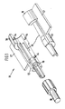
- Figure 1 is an exploded view of a two part introducer employed in the present invention;
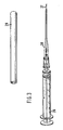
- Figure 2 shows an introducer assembly comprising the introducer of Figure 1, a catheter and a sheath;
- Figure 3 shows a syringe assembly and cannulated needle for use with the present invention;
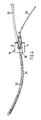
- Figure 4 corresponds to Figure 2 and illustrates a stage in the catheter insertion process; and
- Figure 5 illustrates a winged connector for use with the present invention.
- The introducer assembly described hereinafter is supplied in a sealed and sterilized container (not shown) and is removed therefrom immediately prior to use.
- With reference to Figure 1 there is shown an
introducer 11 comprising two substantiallysymmetrical parts projections 14 and corresponding holes (not shown) to locate one part relative to the other. The introducer is moulded in a relatively hard plastic and may be transparent. - In the assembled condition the introducer defines a
tube 15 having a tubular member orannular shield 16 around the proximal end thereof andfinger grips 17. Theshield 16 is connected to the mid-portion of thetube 15 by an axially extending arm, of generally "u" shaped section; the underside of the tube is connected to the arm at a part more proximal than the upper surface and the intermediate portion is moulded to provide smooth transition around the tube. The arrangement of tube and arm define an opening in the upper surface of the assembled introducer. - The distal end of the tube has a luer taper, for engagement with a cannula, and is closed by a
cap 18. Ablood check valve 19 is disposed within the tube and retained in one half thereof as shown; the valve has a slit for removal from the catheter as will be described hereinafter. - With reference to Figure 2 there is shown an introducer assembly including a
sheath 21 of resilient transparent material and having a continuous slit along the length thereof; the slit is closed by the natural resiliency of the material. The material of the sheath is of sufficient resilience to prevent the slit opening when the sheath is bent. Thesheath 21 is fitted at one end to the introducer around the proximal end of thetube 15 and within theshield 16. - Within the
sheath 21 is a freely slidable catheter 22 h aving depth graduations thereon; the sheath is shown open for illustration purposes only. The distal end of the catheter is inserted into thetube 15. The proximal end of the catheter has an end fitting 23, which may have a female luer taper, and is closed by acap 24. The proximal end of the sheath engages thefitting 23 as shown. - With reference to Figure 3 there is shown a
syringe 26 having aneedle 27 and surroundingplastics cannula 28. Aprotective cap 29 is provided for the cannulated needle. The cannula is of translucent or preferably transparent material. - Use of the apparatus will now be described. The syringe and cannulated needle is taken out of the usual sterile pack and the
cap 29 removed. The needle is inserted into the desired blood vessel and blood passes into the syringe confirming that the needle is correctly inserted. Thecannula 28 is pushed off the tip of thesyringe 26 into the blood vessel and thesyringe 26 andneedle 27 withdrawn for disposal. - The introducer assembly, which has previously been removed from its sterile pack, is attached to the funnel end of the cannula. The cannula is firmly held by one hand whilst the sheath is moved distally through the
shield 16; this initial movement causes thecatheter 22 to be advanced through theblood check valve 19 andcannula 28 into the blood vessel. The sheath slit opens around thetube 15 and the distal end of the sheath emerges through the side aperture of the introducer as shown in Figure 4. Further distal movement of thecatheter 22 can be accomplished by pulling the free end of thesheath 21; this gives smooth uninterrupted movement of the catheter into the blood vessel; the sheath is maintained under tension giving greater control and feel to the user. - The catheter graduations, best shown in Figure 4, indicate when the desired depth of insertion is reached. The user then removes the remainder of the sheath and separates the introducer and cannula. The introducer is split into the two parts for disposal and the blood check valve removed from the catheter. The cannula is removed from the blood vessel and may be splittable in any known manner for removal from the catheter and disposal; for example the cannula may have a longitudinally extending line of incompatible material. The proximal end of the catheter is attached to other medical apparatus, for example an intravenous drip, in the usual way.
- Figure 4 illustrates a catheter without a proximal connector, the
sheath 21 is closed at the proximal end thereof to provide a sterile environment for the catheter. After thecatheter 22 has been inserted to the desired depth, the excess distal portion may be cut off and thewinged extension tube 31 of Figure 5 inserted after theprotective cover 32 is first removed. Theextension tube 31 has at one end a capilliary extension 34 for connection to the catheter, and at the other end afemale connector 35 closed by aremovable plug 36 which may be removed for connection of thetube 31 to external apparatus. Thewings 33 may be attached to the patient's skin by tape or by sutures through the holes shown. Theextension tube 31 has asleeve 37 at the proximal end thereof to permit the tube to be gripped by forceps without damage thereto. - Where the catheter does not have a proximal connector or where the proximal connector is to be cut off, a one-piece introducer moulding is permissible.
- The
extension tube 31 can be firmly fixed to the patient's skin without stressing the catheter and can be removed and replaced easily should the female connector become damaged through repeated connection and disconnection of infusion apparatus. Thecatheter 22 can remain undisturbed in the patient whilst the extension tube is replaced. - The cannula, introducer and sheath are preferably transparent so that the user can visualise the depth markings on the catheter.
- The applicants do not intend the scope of the invention to be limited by the above description of a preferred embodiment but only by the claims appended hereto.
Claims (4)
- A catheter introducer assembly comprising a catheter (22), a sheath (21) therefor and a cannula (28), wherein the tubular sheath 21 is telescoped over said catheter (22), and includes an introducer (11) comprising a tubular member (16) having a distal arm extending axially thereof, and a tube (15) attached to said arm and extending proximally into said tubular member (16) and being spaced from the inner wall thereof, said introducer (11) being slidably telescoped on said catheter (22), for separating the sheath (21) from said catheter (22) responsive to movement of the catheter (22) through said introducer (11) and for inserting said catheter (22) to a selected depth from within said sheath into a blood vessel while maintaining sterility of said catheter (22) until said catheter enters the blood vessel, and the cannula (28) has distal and proximal ends, wherein said introducer (11) attaches to the proximal end thereof and the distal end of said cannula (28) can be inserted into a blood vessel to allow the catheter (22) to pass from said introducer (11) into the blood vessel, said introducer (11) having a side opening through which the sheath (21) can be pulled and removed from the catheter (22).
- An assembly as claimed in Claim 1, characterised in that the introducer (11) is moulded in two substantially symmetrical parts which fit together about the catheter (22) and which are removable by splitting.
- A assembly as claimed in Claim 1, or Claim 2, characterised in that the introducer (11) is transparent, and said sheath (21) is longitudinally splittable from around said tube (15) as the sheath (21) is moved with the catheter through the proximal end of the introducer (11).
- A catheter introducer assembly as claimed in any one of the preceding Claims characterised in that the introducer (11) incorporates a blood check valve (19) disposed within the inner tube (15).
Priority Applications (1)
| Application Number | Priority Date | Filing Date | Title |
|---|---|---|---|
| AT86309448T ATE70459T1 (en) | 1985-12-06 | 1986-12-04 | DISPOSABLE CATHETER INSERTION DEVICE. |
Applications Claiming Priority (2)
| Application Number | Priority Date | Filing Date | Title |
|---|---|---|---|
| JP60274573A JPS62133969A (en) | 1985-12-06 | 1985-12-06 | Disposable catheter introducing apparatus for staying in blood vessel |
| JP274573/85 | 1985-12-06 |
Publications (3)
| Publication Number | Publication Date |
|---|---|
| EP0226397A2 EP0226397A2 (en) | 1987-06-24 |
| EP0226397A3 EP0226397A3 (en) | 1988-03-30 |
| EP0226397B1 true EP0226397B1 (en) | 1991-12-18 |
Family
ID=17543621
Family Applications (1)
| Application Number | Title | Priority Date | Filing Date |
|---|---|---|---|
| EP86309448A Expired - Lifetime EP0226397B1 (en) | 1985-12-06 | 1986-12-04 | Disposable catheter insertion apparatus |
Country Status (9)
| Country | Link |
|---|---|
| US (1) | US4913704A (en) |
| EP (1) | EP0226397B1 (en) |
| JP (1) | JPS62133969A (en) |
| AT (1) | ATE70459T1 (en) |
| CA (1) | CA1276849C (en) |
| DE (1) | DE3683026D1 (en) |
| ES (1) | ES2027638T3 (en) |
| HK (1) | HK86692A (en) |
| SG (1) | SG55292G (en) |
Cited By (1)
| Publication number | Priority date | Publication date | Assignee | Title |
|---|---|---|---|---|
| US9504398B2 (en) | 2002-08-24 | 2016-11-29 | St. Jude Medical, Atrial Fibrillation Division, Inc. | Methods and apparatus for locating the fossa ovalis and performing transseptal puncture |
Families Citing this family (45)
| Publication number | Priority date | Publication date | Assignee | Title |
|---|---|---|---|---|
| US4840613A (en) * | 1988-04-27 | 1989-06-20 | Menlo Care, Inc. | Protective sheath for catheter assembly |
| US5211651A (en) * | 1989-08-18 | 1993-05-18 | Evi Corporation | Catheter atherotome |
| US5156610A (en) * | 1989-08-18 | 1992-10-20 | Evi Corporation | Catheter atherotome |
| US5282484A (en) * | 1989-08-18 | 1994-02-01 | Endovascular Instruments, Inc. | Method for performing a partial atherectomy |
| JP3036835B2 (en) * | 1989-08-18 | 2000-04-24 | イーブイアイ コーポレイション | Catheter atherotome |
| JP2676411B2 (en) * | 1989-08-31 | 1997-11-17 | 本田技研工業株式会社 | Handle lock device and engine ignition device |
| US5160342A (en) * | 1990-08-16 | 1992-11-03 | Evi Corp. | Endovascular filter and method for use thereof |
| US5239982A (en) * | 1991-06-07 | 1993-08-31 | Baxter International Inc. | Catheter depth gauge and method of use |
| US5312355A (en) * | 1991-07-09 | 1994-05-17 | H L Medical Inventions, Inc. | Splittable hemostatic valve and sheath and the method for using the same |
| US5643297A (en) | 1992-11-09 | 1997-07-01 | Endovascular Instruments, Inc. | Intra-artery obstruction clearing apparatus and methods |
| US5571122A (en) | 1992-11-09 | 1996-11-05 | Endovascular Instruments, Inc. | Unitary removal of plaque |
| GB2290030B (en) * | 1994-06-09 | 1998-01-07 | Smiths Industries Plc | Needle assemblies |
| US5836306A (en) * | 1994-12-23 | 1998-11-17 | Bard Connaught | Exchange accessory for use with a monorail catheter |
| AUPP550098A0 (en) * | 1998-08-26 | 1998-09-17 | Microcatheters Pty Ltd | Catheter guide |
| US6382209B1 (en) * | 1999-10-14 | 2002-05-07 | Frederic J Toye | Apparatus and method enabling location of trachea breathing tube in body viscus |
| US6786884B1 (en) * | 1999-10-29 | 2004-09-07 | Bard Access Systems, Inc. | Bolus tip design for a multi-lumen catheter |
| US6508790B1 (en) | 1999-11-15 | 2003-01-21 | William K. Lawrence | Vascular access sheath |
| US6592553B2 (en) * | 2000-07-05 | 2003-07-15 | Cardiac Pacemakers, Inc. | Introducer assembly and method therefor |
| US20060264979A1 (en) * | 2005-05-20 | 2006-11-23 | Shepard Rudolph C | Novel enhanced vascular surgical device |
| AU2006264300B2 (en) | 2005-07-06 | 2012-03-08 | Vascular Pathways Inc. | Intravenous catheter insertion device and method of use |
| US8029481B2 (en) | 2006-10-17 | 2011-10-04 | Matthew Dickson Reavill | Apparatus and method of inserting an infusing catheter and determining catheter depth without a guidewire or direct contact with the catheter |
| WO2008103306A1 (en) * | 2007-02-21 | 2008-08-28 | Tyco Healthcare Group Lp | Expandable surgical portal |
| DE602008003791D1 (en) | 2007-05-07 | 2011-01-13 | Vascular Pathways Inc | INTRODUCTION OF INTRAVENOUS CATHETER AND BLOOD DETECTING DEVICE AND METHOD OF USE |
| WO2009039013A1 (en) * | 2007-09-17 | 2009-03-26 | Icu Medical, Inc. | Insertion devices for infusion devices |
| US10384039B2 (en) | 2010-05-14 | 2019-08-20 | C. R. Bard, Inc. | Catheter insertion device including top-mounted advancement components |
| US9872971B2 (en) | 2010-05-14 | 2018-01-23 | C. R. Bard, Inc. | Guidewire extension system for a catheter placement device |
| US9950139B2 (en) | 2010-05-14 | 2018-04-24 | C. R. Bard, Inc. | Catheter placement device including guidewire and catheter control elements |
| JP6243735B2 (en) * | 2010-05-14 | 2017-12-06 | シー・アール・バード・インコーポレーテッドC R Bard Incorporated | Catheter placement apparatus and method |
| US11925779B2 (en) | 2010-05-14 | 2024-03-12 | C. R. Bard, Inc. | Catheter insertion device including top-mounted advancement components |
| US8932258B2 (en) * | 2010-05-14 | 2015-01-13 | C. R. Bard, Inc. | Catheter placement device and method |
| US8328759B2 (en) | 2010-08-13 | 2012-12-11 | William Joseph Donawick | Intraluminal cannula placement apparatus utilizing a specialized cannula for use with a previously inserted I.V. catheter |
| US20120130218A1 (en) * | 2010-11-23 | 2012-05-24 | Kauphusman James V | Medical devices having an electroanatomical system imaging element mounted thereon |
| US8690833B2 (en) | 2011-01-31 | 2014-04-08 | Vascular Pathways, Inc. | Intravenous catheter and insertion device with reduced blood spatter |
| EP3563898B1 (en) | 2011-02-25 | 2020-11-11 | C.R. Bard, Inc. | Medical component insertion device including a retractable needle |
| USD903101S1 (en) | 2011-05-13 | 2020-11-24 | C. R. Bard, Inc. | Catheter |
| US9522254B2 (en) | 2013-01-30 | 2016-12-20 | Vascular Pathways, Inc. | Systems and methods for venipuncture and catheter placement |
| WO2016037127A1 (en) | 2014-09-05 | 2016-03-10 | C.R. Bard, Inc. | Catheter insertion device including retractable needle |
| USD903100S1 (en) | 2015-05-01 | 2020-11-24 | C. R. Bard, Inc. | Catheter placement device |
| SG10202006540RA (en) | 2015-05-15 | 2020-08-28 | Bard Inc C R | Catheter placement device including an extensible needle safety component |
| WO2018049413A1 (en) | 2016-09-12 | 2018-03-15 | C.R. Bard, Inc. | Blood control for a catheter insertion device |
| CA3054969A1 (en) | 2017-03-01 | 2018-09-07 | C.R. Bard, Inc. | Catheter insertion device |
| CN111801133B (en) | 2018-03-07 | 2022-12-06 | 巴德阿克塞斯系统股份有限公司 | Guidewire advancement and blood flashback system for medical device insertion systems |
| USD921884S1 (en) | 2018-07-27 | 2021-06-08 | Bard Access Systems, Inc. | Catheter insertion device |
| CN109077778B (en) * | 2018-08-09 | 2020-12-01 | 天津大学 | Ureter soft lens pushing mechanism and surgical instrument using same |
| CN112386778A (en) | 2019-08-19 | 2021-02-23 | 贝克顿·迪金森公司 | Midline catheter placement device |
Family Cites Families (12)
| Publication number | Priority date | Publication date | Assignee | Title |
|---|---|---|---|---|
| DE3100442C1 (en) * | 1962-05-08 | 1982-09-30 | Dr. Eduard Fresenius, Chemisch-pharmazeutische Industrie KG, 6380 Bad Homburg | Adapter piece for plastic cannulas and vein catheters |
| US3825001A (en) * | 1972-12-05 | 1974-07-23 | Johnson & Johnson | Catheter placement unit |
| FR2263789A1 (en) * | 1974-03-13 | 1975-10-10 | Transcodan | Flexible catheter insertion nozzle - is sealed from bacteria in wing area by easily opened housing |
| FR2439591A1 (en) * | 1978-10-25 | 1980-05-23 | Technological Supply | DEVICE FOR INTRODUCING A CATHETER OR PROBE INTO A BLOOD VESSEL |
| USRE31855F1 (en) * | 1978-12-01 | 1986-08-19 | Tear apart cannula | |
| US4392853A (en) * | 1981-03-16 | 1983-07-12 | Rudolph Muto | Sterile assembly for protecting and fastening an indwelling device |
| US4417886A (en) * | 1981-11-05 | 1983-11-29 | Arrow International, Inc. | Catheter introduction set |
| FR2522504B1 (en) * | 1982-03-05 | 1985-07-12 | Durand Alain | CATHETERIZATION DEVICE FOR USE IN PERFUSIONS IN THE MEDICAL AND VETERINARY FIELDS |
| FR2522507A1 (en) * | 1982-03-05 | 1983-09-09 | Vermed Laboratoire Pharmaceuti | Catheter tube of flexible silicone rubber - with an internal support rod for injection or withdrawal of fluids via multi-purpose coupling |
| US4449973A (en) * | 1982-06-26 | 1984-05-22 | Luther Medical Products, Inc. | Small gauge, pre-split cannula and process for manufacture |
| US4581025A (en) * | 1983-11-14 | 1986-04-08 | Cook Incorporated | Sheath |
| US4655750A (en) * | 1985-11-22 | 1987-04-07 | Manresa, Inc. | Closed system catheter with guide wire |
-
1985
- 1985-12-06 JP JP60274573A patent/JPS62133969A/en active Pending
-
1986
- 1986-12-04 EP EP86309448A patent/EP0226397B1/en not_active Expired - Lifetime
- 1986-12-04 DE DE8686309448T patent/DE3683026D1/en not_active Expired - Lifetime
- 1986-12-04 AT AT86309448T patent/ATE70459T1/en not_active IP Right Cessation
- 1986-12-04 ES ES198686309448T patent/ES2027638T3/en not_active Expired - Lifetime
- 1986-12-05 CA CA000524716A patent/CA1276849C/en not_active Expired - Lifetime
-
1988
- 1988-10-26 US US07/263,979 patent/US4913704A/en not_active Expired - Lifetime
-
1992
- 1992-05-23 SG SG55292A patent/SG55292G/en unknown
- 1992-11-05 HK HK866/92A patent/HK86692A/en not_active IP Right Cessation
Cited By (1)
| Publication number | Priority date | Publication date | Assignee | Title |
|---|---|---|---|---|
| US9504398B2 (en) | 2002-08-24 | 2016-11-29 | St. Jude Medical, Atrial Fibrillation Division, Inc. | Methods and apparatus for locating the fossa ovalis and performing transseptal puncture |
Also Published As
| Publication number | Publication date |
|---|---|
| ES2027638T3 (en) | 1992-06-16 |
| ATE70459T1 (en) | 1992-01-15 |
| HK86692A (en) | 1992-11-13 |
| EP0226397A3 (en) | 1988-03-30 |
| DE3683026D1 (en) | 1992-01-30 |
| US4913704A (en) | 1990-04-03 |
| JPS62133969A (en) | 1987-06-17 |
| SG55292G (en) | 1992-07-24 |
| EP0226397A2 (en) | 1987-06-24 |
| CA1276849C (en) | 1990-11-27 |
Similar Documents
| Publication | Publication Date | Title |
|---|---|---|
| EP0226397B1 (en) | Disposable catheter insertion apparatus | |
| EP0093164B1 (en) | Catheter introduction set | |
| US7556617B2 (en) | Catheter safety needle | |
| US7001396B2 (en) | Safety introducer assembly and method | |
| EP1131129B1 (en) | Blood seal having a spring-biased septum | |
| EP0440479B1 (en) | Catheter with controlled valve | |
| EP1028775B1 (en) | Medical Introducing device with flared sheath end | |
| US4781692A (en) | Retractable safety needles | |
| US7060055B2 (en) | Forward shielding safety device | |
| US4177809A (en) | Intravenous catheter apparatus and method | |
| US4068659A (en) | Catheter placement assembly | |
| EP0392765B1 (en) | Catheter with needle guard | |
| EP0588996B1 (en) | Lead introducer with mechanical opening valve | |
| US4412832A (en) | Peelable catheter introduction device | |
| US5902274A (en) | Catheter assembly | |
| EP0314470B1 (en) | Needle protector | |
| US8551051B2 (en) | Safety shield for medical needles | |
| US4509944A (en) | Catheter assembly | |
| WO1998017335A1 (en) | Double lumen introducing needle | |
| AU9749701A (en) | Blood collection set | |
| WO2004054654A1 (en) | A catheter introducer assembly having safety shielded needle before and after use | |
| EP0448395A1 (en) | Stickless catheter with interconnecting nose | |
| US4192306A (en) | Catheter placement assembly having axial and rotational alignment means | |
| US4304231A (en) | Catheter with wire stylet | |
| EP0578367A1 (en) | Catheter with needle guard and extended flash chamber |
Legal Events
| Date | Code | Title | Description |
|---|---|---|---|
| PUAI | Public reference made under article 153(3) epc to a published international application that has entered the european phase |
Free format text: ORIGINAL CODE: 0009012 |
|
| AK | Designated contracting states |
Kind code of ref document: A2 Designated state(s): AT BE CH DE ES FR GB IT LI LU NL SE |
|
| PUAL | Search report despatched |
Free format text: ORIGINAL CODE: 0009013 |
|
| RHK1 | Main classification (correction) |
Ipc: A61M 25/00 |
|
| AK | Designated contracting states |
Kind code of ref document: A3 Designated state(s): AT BE CH DE ES FR GB IT LI LU NL SE |
|
| 17P | Request for examination filed |
Effective date: 19880826 |
|
| 17Q | First examination report despatched |
Effective date: 19900115 |
|
| GRAA | (expected) grant |
Free format text: ORIGINAL CODE: 0009210 |
|
| ITF | It: translation for a ep patent filed |
Owner name: BARZANO' E ZANARDO MILANO S.P.A. |
|
| AK | Designated contracting states |
Kind code of ref document: B1 Designated state(s): AT BE CH DE ES FR GB IT LI LU NL SE |
|
| PG25 | Lapsed in a contracting state [announced via postgrant information from national office to epo] |
Ref country code: AT Effective date: 19911218 |
|
| REF | Corresponds to: |
Ref document number: 70459 Country of ref document: AT Date of ref document: 19920115 Kind code of ref document: T |
|
| REF | Corresponds to: |
Ref document number: 3683026 Country of ref document: DE Date of ref document: 19920130 |
|
| ET | Fr: translation filed | ||
| REG | Reference to a national code |
Ref country code: ES Ref legal event code: FG2A Ref document number: 2027638 Country of ref document: ES Kind code of ref document: T3 |
|
| PLBE | No opposition filed within time limit |
Free format text: ORIGINAL CODE: 0009261 |
|
| STAA | Information on the status of an ep patent application or granted ep patent |
Free format text: STATUS: NO OPPOSITION FILED WITHIN TIME LIMIT |
|
| PGFP | Annual fee paid to national office [announced via postgrant information from national office to epo] |
Ref country code: LU Payment date: 19921204 Year of fee payment: 7 |
|
| 26N | No opposition filed | ||
| EPTA | Lu: last paid annual fee | ||
| PG25 | Lapsed in a contracting state [announced via postgrant information from national office to epo] |
Ref country code: LU Free format text: LAPSE BECAUSE OF NON-PAYMENT OF DUE FEES Effective date: 19931204 |
|
| EAL | Se: european patent in force in sweden |
Ref document number: 86309448.8 |
|
| REG | Reference to a national code |
Ref country code: GB Ref legal event code: 732E |
|
| NLS | Nl: assignments of ep-patents |
Owner name: SHERWOOD SERVICES AG;TYCO GROUP S.A.R.L. |
|
| REG | Reference to a national code |
Ref country code: CH Ref legal event code: PUE Owner name: SHERWOOD MEDICAL COMPANY TRANSFER- TYCO GROUP S.A. |
|
| REG | Reference to a national code |
Ref country code: FR Ref legal event code: TP |
|
| BECA | Be: change of holder's address |
Free format text: 20010131 *SHERWOOD SERVICES A.G.:SCHWERTSTRASSE 9, 8200 SCHAFFHAUSEN |
|
| BECH | Be: change of holder |
Free format text: 20010131 *SHERWOOD SERVICES A.G.:SCHWERTSTRASSE 9, 8200 SCHAFFHAUSEN |
|
| REG | Reference to a national code |
Ref country code: GB Ref legal event code: IF02 |
|
| PGFP | Annual fee paid to national office [announced via postgrant information from national office to epo] |
Ref country code: NL Payment date: 20051116 Year of fee payment: 20 |
|
| PGFP | Annual fee paid to national office [announced via postgrant information from national office to epo] |
Ref country code: GB Payment date: 20051130 Year of fee payment: 20 |
|
| PGFP | Annual fee paid to national office [announced via postgrant information from national office to epo] |
Ref country code: FR Payment date: 20051216 Year of fee payment: 20 |
|
| PGFP | Annual fee paid to national office [announced via postgrant information from national office to epo] |
Ref country code: ES Payment date: 20051226 Year of fee payment: 20 |
|
| PGFP | Annual fee paid to national office [announced via postgrant information from national office to epo] |
Ref country code: SE Payment date: 20051227 Year of fee payment: 20 Ref country code: CH Payment date: 20051227 Year of fee payment: 20 |
|
| REG | Reference to a national code |
Ref country code: GB Ref legal event code: PE20 |
|
| PGFP | Annual fee paid to national office [announced via postgrant information from national office to epo] |
Ref country code: IT Payment date: 20051229 Year of fee payment: 20 |
|
| PGFP | Annual fee paid to national office [announced via postgrant information from national office to epo] |
Ref country code: DE Payment date: 20060131 Year of fee payment: 20 |
|
| PGFP | Annual fee paid to national office [announced via postgrant information from national office to epo] |
Ref country code: BE Payment date: 20060202 Year of fee payment: 20 |
|
| PG25 | Lapsed in a contracting state [announced via postgrant information from national office to epo] |
Ref country code: GB Free format text: LAPSE BECAUSE OF EXPIRATION OF PROTECTION Effective date: 20061203 |
|
| PG25 | Lapsed in a contracting state [announced via postgrant information from national office to epo] |
Ref country code: NL Free format text: LAPSE BECAUSE OF EXPIRATION OF PROTECTION Effective date: 20061204 |
|
| PG25 | Lapsed in a contracting state [announced via postgrant information from national office to epo] |
Ref country code: ES Free format text: LAPSE BECAUSE OF EXPIRATION OF PROTECTION Effective date: 20061205 |
|
| REG | Reference to a national code |
Ref country code: CH Ref legal event code: PL |
|
| NLV7 | Nl: ceased due to reaching the maximum lifetime of a patent |
Effective date: 20061204 |
|
| EUG | Se: european patent has lapsed | ||
| REG | Reference to a national code |
Ref country code: ES Ref legal event code: FD2A Effective date: 20061205 |
|
| BE20 | Be: patent expired |
Owner name: *SHERWOOD SERVICES A.G. Effective date: 20061204 |