EP0226939A2 - Apparatus and method for forming a fibrous web - Google Patents
Apparatus and method for forming a fibrous web Download PDFInfo
- Publication number
- EP0226939A2 EP0226939A2 EP86117146A EP86117146A EP0226939A2 EP 0226939 A2 EP0226939 A2 EP 0226939A2 EP 86117146 A EP86117146 A EP 86117146A EP 86117146 A EP86117146 A EP 86117146A EP 0226939 A2 EP0226939 A2 EP 0226939A2
- Authority
- EP
- European Patent Office
- Prior art keywords
- forming
- web
- forming surface
- vacuum
- layer
- Prior art date
- Legal status (The legal status is an assumption and is not a legal conclusion. Google has not performed a legal analysis and makes no representation as to the accuracy of the status listed.)
- Granted
Links
Images


Classifications
-
- D—TEXTILES; PAPER
- D04—BRAIDING; LACE-MAKING; KNITTING; TRIMMINGS; NON-WOVEN FABRICS
- D04H—MAKING TEXTILE FABRICS, e.g. FROM FIBRES OR FILAMENTARY MATERIAL; FABRICS MADE BY SUCH PROCESSES OR APPARATUS, e.g. FELTS, NON-WOVEN FABRICS; COTTON-WOOL; WADDING ; NON-WOVEN FABRICS FROM STAPLE FIBRES, FILAMENTS OR YARNS, BONDED WITH AT LEAST ONE WEB-LIKE MATERIAL DURING THEIR CONSOLIDATION
- D04H1/00—Non-woven fabrics formed wholly or mainly of staple fibres or like relatively short fibres
- D04H1/70—Non-woven fabrics formed wholly or mainly of staple fibres or like relatively short fibres characterised by the method of forming fleeces or layers, e.g. reorientation of fibres
- D04H1/72—Non-woven fabrics formed wholly or mainly of staple fibres or like relatively short fibres characterised by the method of forming fleeces or layers, e.g. reorientation of fibres the fibres being randomly arranged
- D04H1/736—Non-woven fabrics formed wholly or mainly of staple fibres or like relatively short fibres characterised by the method of forming fleeces or layers, e.g. reorientation of fibres the fibres being randomly arranged characterised by the apparatus for arranging fibres
-
- A—HUMAN NECESSITIES
- A61—MEDICAL OR VETERINARY SCIENCE; HYGIENE
- A61F—FILTERS IMPLANTABLE INTO BLOOD VESSELS; PROSTHESES; DEVICES PROVIDING PATENCY TO, OR PREVENTING COLLAPSING OF, TUBULAR STRUCTURES OF THE BODY, e.g. STENTS; ORTHOPAEDIC, NURSING OR CONTRACEPTIVE DEVICES; FOMENTATION; TREATMENT OR PROTECTION OF EYES OR EARS; BANDAGES, DRESSINGS OR ABSORBENT PADS; FIRST-AID KITS
- A61F13/00—Bandages or dressings; Absorbent pads
- A61F13/15—Absorbent pads, e.g. sanitary towels, swabs or tampons for external or internal application to the body; Supporting or fastening means therefor; Tampon applicators
- A61F13/15577—Apparatus or processes for manufacturing
- A61F13/15617—Making absorbent pads from fibres or pulverulent material with or without treatment of the fibres
- A61F13/15658—Forming continuous, e.g. composite, fibrous webs, e.g. involving the application of pulverulent material on parts thereof
-
- B—PERFORMING OPERATIONS; TRANSPORTING
- B27—WORKING OR PRESERVING WOOD OR SIMILAR MATERIAL; NAILING OR STAPLING MACHINES IN GENERAL
- B27N—MANUFACTURE BY DRY PROCESSES OF ARTICLES, WITH OR WITHOUT ORGANIC BINDING AGENTS, MADE FROM PARTICLES OR FIBRES CONSISTING OF WOOD OR OTHER LIGNOCELLULOSIC OR LIKE ORGANIC MATERIAL
- B27N3/00—Manufacture of substantially flat articles, e.g. boards, from particles or fibres
- B27N3/08—Moulding or pressing
- B27N3/10—Moulding of mats
- B27N3/14—Distributing or orienting the particles or fibres
-
- D—TEXTILES; PAPER
- D04—BRAIDING; LACE-MAKING; KNITTING; TRIMMINGS; NON-WOVEN FABRICS
- D04H—MAKING TEXTILE FABRICS, e.g. FROM FIBRES OR FILAMENTARY MATERIAL; FABRICS MADE BY SUCH PROCESSES OR APPARATUS, e.g. FELTS, NON-WOVEN FABRICS; COTTON-WOOL; WADDING ; NON-WOVEN FABRICS FROM STAPLE FIBRES, FILAMENTS OR YARNS, BONDED WITH AT LEAST ONE WEB-LIKE MATERIAL DURING THEIR CONSOLIDATION
- D04H1/00—Non-woven fabrics formed wholly or mainly of staple fibres or like relatively short fibres
- D04H1/70—Non-woven fabrics formed wholly or mainly of staple fibres or like relatively short fibres characterised by the method of forming fleeces or layers, e.g. reorientation of fibres
- D04H1/72—Non-woven fabrics formed wholly or mainly of staple fibres or like relatively short fibres characterised by the method of forming fleeces or layers, e.g. reorientation of fibres the fibres being randomly arranged
- D04H1/732—Non-woven fabrics formed wholly or mainly of staple fibres or like relatively short fibres characterised by the method of forming fleeces or layers, e.g. reorientation of fibres the fibres being randomly arranged by fluid current, e.g. air-lay
-
- D—TEXTILES; PAPER
- D21—PAPER-MAKING; PRODUCTION OF CELLULOSE
- D21F—PAPER-MAKING MACHINES; METHODS OF PRODUCING PAPER THEREON
- D21F11/00—Processes for making continuous lengths of paper, or of cardboard, or of wet web for fibre board production, on paper-making machines
- D21F11/006—Making patterned paper
-
- D—TEXTILES; PAPER
- D21—PAPER-MAKING; PRODUCTION OF CELLULOSE
- D21F—PAPER-MAKING MACHINES; METHODS OF PRODUCING PAPER THEREON
- D21F9/00—Complete machines for making continuous webs of paper
Definitions
- the present invention relates to an apparatus and a method for forming fibrous webs.
- Absorbent disposable articles such as diapers, feminine napkins and incontinence garments, employ absorbent batts to absorb body fluids, such as urine. It has generally been desirable to form a contoured batt or pad which locates more absorbent material in those areas which are subjected to higher levels of fluid loading. Various types of conventional machines have been employed to manufacture such contoured pads.
- U.S. Patent 4,388,056 issued June 14, 1983 to F. B. Lee, et al. discloses an apparatus for continuously forming a cyclically contoured and densified air-laid fibrous web.
- the web has alternately spaced narrow regions with relatively high basis weight and wide regions with relatively low basis weight.
- Adjustable shutter plates are configured to span a plurality of transverse plenum segments to modulate the air flow through the device.
- U.S. Patent 3,682,761 issued August 8, 1972 to C. A. Lee, et al. discloses a device for forming an elongated air-laid web.
- This web has a longitudinally extending central portion and integral longitudinally extending portions flanking the central portion.
- This web also has a generally stepped configuration with a greater average thickness in the central portion than in the side portions.
- the device taught by C. A. Lee, et al. employs baffles to direct more fibrous material toward the central portion of the web, and employs a plurality of valves to increase the amount of suction through the central portion of the web to induce the formation of a greater thickness at that central portion.
- U.S. Patent 4,005,957 issued February 1, 1977 to P. Savich discloses a device which has a screen with pockets formed therein and which is employed to manufacture fibrous pads.
- U.S. Patent 3,973,291 issued August 10, 1976 to C. G. Kolbach discloses a method and apparatus for forming discrete fibrous pads which have contoured thickness.
- the method and apparatus disclosed by Kolbach employ a sequence of masks which completely block off a source of applied vacuum to all sections of each pad receiving compartment except that section in which a region of a fibrous pad having a particular weight of fibers per unit area is to be formed.
- U.S. Patent 4,016,628 issued April 12, 1977 to C. C. Kolbach discloses a device for forming an air-laid fibrous web having a medial portion of greater basis weight than flanking end and side portions.
- the apparatus includes a vacuum box which has an open end underlying a discrete section of a foraminous forming surface.
- Vacuum connection means establish a greater pressure drop across the discrete section of the foraminous forming surface overlying the open end of the vacuum box than across the regions of the foraminous forming surface extending beyond the edges of the vacuum box.
- U.S. Patent 3,962,753 issued June 15, 1976 to J. W. Dunn discloses a device for forming a fibrous glass strand mat.
- the apparatus includes a panel having a plurality of spaced apertures located underneath a foraminous conveyor.
- the plate creates a back pressure and a relatively static high pressure area immediately above the conveyor. This eliminates the problem of random movement of the fibers after deposition on the conveyor, and reduces the air circulation to permit an even distribution of the fibers on the mat.
- U.S. Patent 4,103,058 issued July 25, 1978 to L. D. Humlicek discloses a blown microfiber web having a network of compacted high-density regions and pillowed low density regions.
- the web may be collected on a perforated screen so that the microfibers deposited on the land area of the screen form the compacted high density regions and microfibers deposited over the openings of the screen formed the pillowed low density regions.
- the invention allows a controlled formation of light and heavy fluff zones.
- the invention also provides a method and an apparatus for forming an absorbent batt that has tailored absorbency zones. Certain zones or areas have a higher basis weight and a correspondingly higher absorbency than other zones.
- the apparatus of the invention includes a fiber supply means for providing fibers of web material. These fibers are deposited on a foraminous web forming layer, which is supported by a foraminous spacing means.
- the foraminous spacing means supports the web forming layer in a configuration which allows a substantially unrestricted gas flow from a region immediately adjacent to and downstream from the web forming layer.
- a gas flow regulating layer has a selected pattern of apertures therethrough, and is fixedly positioned in adjacent, facing relation with the foraminous spacing means to provide a selected pattern of gas flow through the web forming layer.
- the foraminous web forming layer, the foraminous spacing means and the gas flow regulating layer are constructed to form an installable and replaceable assembly, and flow forcing means provide a selected flow of gas through the web forming layer.
- the invention further provides a method for forming a fibrous web, which includes the step of depositing fibers of web material onto a foraminous web forming layer.
- the web forming layer is supported in a configuration which allows a substantially unrestricted gas flow from a region immediately adjacent to and downstream from the web forming layer.
- a selected pattern of gas flow is directed through the web forming layer by a gas flow regulating layer, which has a selected pattern of apertures therethrough and is fixedly positioned downstream from the web forming layer.
- the foraminous web forming layer, the foraminous spacing means and the gas flow regulating layer are constructed to form an installable and replaceable assembly, and a suitable flow of gas is forced through the web forming layer.
- the method and apparatus of the invention can advantageously provide a web forming assembly which includes a gas flow regulating mechanism and is readily installable on and removable from an outside portion of a transport means.
- the regulating mechanism is readily adjusted to produce a desired distribution of fiber basis weight across the formed web. Maintenance and set-up time can be reduced, and the forming assembly is less susceptible to clogging by the fibers.
- the method and apparatus of the present invention are particularly useful for forming contoured fibrous webs or pads which have an increased weight of material in selected regions.
- the regions with greater weight of material generally have a corresponding greater degree of absorbency.
- Such contoured absorbent pads are particularly useful in articles that are subjected to a greater fluid loading in certain "target" areas than in other areas. For example, in a baby diaper comprised of the absorbent batt or pad is located between a liquid pervious inner layer and a liquid impervious outer layer, the crotch and front areas of the diaper are more heavily wetted by the infant than the areas closer to the infant's waist or back. A similar situation may also arise in the case of wound dressings, incontinence garments and feminine sanitary napkins.
- Basis weight is intended to designate the weight of fiber material per unit surface area of the web. For example, typical units would be grams/cm .
- the material employed to form the fibrous web is typically composed of an absorbent material, such as a cellulosic material commonly known as "fluff", or the like.
- the web material may include a coformed mixture of cellulosic fibers with polymeric fibers, such as polypropylene fibers, polyethylene fibers, or the like.
- the precursor web material is generally supplied in sheet form, wound into a roll.
- Fibers 10 which enter the system as air-entrained fibers in a stream flowing in the direction indicated by Arrow A, may suitably be derived from a supply of cellulosic, e.g., wood pulp, fibers or other natural or synthetic fibers, which have been subjected to fiberization treatment, i.e., picked apart, in a manner known in the art to provide loose fibers.
- the fibers may be entrained in any other suitable gaseous medium, and references to "air” as the entraining medium herein will be understood to encompass all such other entrainment fluids.
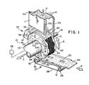
- the stream of air-entrained fibers passes by means of flow channel housing 11 to the forming drum assembly 15.
- the flow channel housing serves to direct and concentrate the air-entrained fibers and to provide a uniform velocity profile in the air/fibers stream.
- the flow channel housing is supported by support members 12a-c, which aggregately form a support frame for the housing and may be anchored and/or joined to other suitable structural elements as necessary or desirable.
- the fibers deposit onto an upstream surface of a replaceable, foraminous web forming assembly 21, which is located on an outer peripheral rim section of a substantially cylindrical drum 18.
- downstream and upstream are determined with respect to the direction of gas flow produced by gas flow forcing means 58.
- this gas flow direction is generally from top to bottom and from the outside of drum 18 to the inside of the drum.
- upstream refers to an orientation in which the gas stream is approaching the reference location
- downstream refers to an orientation in which the gas stream is departing from the reference location.
- the upstream surface of web forming assembly 21 is an outwardly facing surface
- the downstream surface of the assembly is an inwardly facing surface.
- web forming assembly 21 includes a foraminous web forming layer 122, which has an optional pocket recess 22 formed therein and which receives a deposit of the fibers of web material thereon.
- a foraminous spacing means such as one comprised of hardware cloth 121 and spacer sheet member 120, supports web forming layer 122 while allowing a substantially unrestricted gas flow from a region immediately adjacent to and downstream from the web forming layer.
- a gas flow regulating layer 135 has a selected pattern of apertures therethrough and is fixedly positioned in adjacent, facing relation with the foraminous spacing means. This flow regulating layer provides a selected pattern of gas flow through web forming layer 122.
- the combination of the web forming assembly, the foraminous spacing means and the gas flow regulating layer provides a web forming assembly, which as a unit can be replaceably mounted on a selected transport means.
- a transport means such as rotatable drum assembly 15, moves multi-layer web forming assembly 21 along a path which traverses through fiber forming chamber 11.
- the transport means may be comprised of a moveable, endless belt or conveyor, such as representatively shown in U.S. Patent 3,973,291.
- Gas flow forcing means 58 such as a suction pump fan, draws air out from suction chambers formed within drum assembly 15 by way of conduit 23.
- the pump fan creates a pressure differential across multi-layer web forming assembly 21 between the suction chambers and fiber forming chamber 11.
- This pressure differential which can range from about 15 - 25 inches water (about 3.74 - 6.22 kPa), draws the fibers from chamber 11 onto that portion of the surface of web forming assembly 21 located within the boundary confines of the fiber forming chamber.
- drum assembly 15 rotates about shaft 19 to carry web forming assembly 21 through fiber forming chamber 11 and to carry formed web 24 out from chamber 11 to a shaping means, such as scarfing roll 37.
- Scarfing roll 37 rotates about a shaft and contacts the radially outwardly facing free surface of web 24. The movement of the peripheral surface of scarfing roll 37 removes uneven spots from the free surface of web 24 to produce a more uniform and level outer surface on the web.
- a further rotation of drum 18 carries web 24 around to conveyor means 27.
- This conveyor is generally comprised of a flexible screen mesh in the form of an endless belt that moves around a path defined by guide rollers.
- the guide rollers are driven by suitable drive means, such as an electric motor (not shown) to transport web 24 to a desired location.
- Web 24 generally detaches itself from web forming assembly 21 by reason of its own weight and drops onto conveyor 27.
- a selected gas pressure can be applied to help remove web 24 from web forming assembly 21 and drum assembly 15.
- the forming drum assembly 15 comprises a forming drum 18 which is rotatable in the direction of Arrow B. Rotation of the drum is affected by means of the forming drum drive shaft 19 which may be joined to suitable drive means (not shown) such as an electric or other motor directly or indirectly coupled to such shaft.
- the forming drum comprises an air-laid fibrous web laydown zone 20 positioned beneath the air/fibers flow channel housing 11 and configured as a vacuum laydown zone of the foraminous, web forming assembly 21. This vacuum laydown zone constitutes a circumferential cylindrical surface portion of the rotatable drum.
- the vacuum laydown surface has imposed thereon a pressure differential under the action of vacuum suction means (not shown), such as an exhaust blower or other suitable suction means, which suctioningly withdraws air from the arcuate segment of the forming drum associated with the vacuum laydown surface through the air discharge (suction) duct 23, in a manner more fully described hereinafter.
- vacuum suction means such as an exhaust blower or other suitable suction means, which suctioningly withdraws air from the arcuate segment of the forming drum associated with the vacuum laydown surface through the air discharge (suction) duct 23, in a manner more fully described hereinafter.
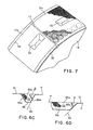
- the foraminous web forming assembly 21 can optionally have therein a series of circumferentially spaced-apart, inverted, generally frusto-pyramidal shaped depressions or pockets provided by contoured surface portions 22 in the surface thereof, of elongate form with their longitudinal axes coincident with the center line of the web forming assembly 21, i.e., the surface portions 22 are typically centered on the forming surface relative to the cross-machine direction.
- the forming drum contains a series of radially extending wall members or baffles 101, 102, 103, 104, 98 and 96, which are stationary, as described more fully in connection with Figures 2 and 3 herein.
- the formed web 24 is removed from the forming surface under the influence of gravity by the weight of the fibrous web 24 and with a pressure differential produced, for example, by pressurized air in blow-off zone ' 100, between baffle plate members 98 and 96, and flowing outwardly through the forming surface in the direction shown by Arrow G.
- a pressure differential produced, for example, by pressurized air in blow-off zone ' 100, between baffle plate members 98 and 96, and flowing outwardly through the forming surface in the direction shown by Arrow G.
- the web 24 is removed from the forming surface onto take-off conveyor 27 comprising endless conveyor belt 28 disposed about rollers 29 and 30, which are respectively positioned on roller shaft members 31 and 32.
- the longitudinally extending fibrous web as removed on the take-off conveyor 27 features a pad 25 corresponding to the concavely contoured surface portions 22 on the forming surface.
- the forming surface may also have disposed thereon symmetrically opposed arcuate blocking plates 40, as shown.
- These blocking plates are particularly advantageous when the forming drum assembly is employed to produce absorbent webs for use in disposable diapers and the like, whereby the blocking plates 40 prevent deposition of fibers on the forming surface to form corresponding arcuate cut-out sections on the finished web (not shown in Figure 1, but as indicated in Figure 8 by the edges 153, 154).
- the longitudinally extending fibrous web 24 prior to its removal from the forming drum passes through the scarfing zone defined by the scarfing roll assembly 35.
- the scarfing roll assembly in turn comprises scarfing roll housing 36 containing scarfing roll 37 disposed on a scarfing roller shaft member 38, driven by means which for simplicity are not shown, but which may be any suitable motive means, and for example may involve coupling by gear or other means to the motor or drive means for the rotatable drum 18.
- the scarfing roll assembly constitutes trimming means for trimming the excess radial thickness of the laid fibrous web deposited on the web forming assembly 21 to yield a laid fibrous web having a substantially uniform, flat cross-direction contour on one major face surface thereof.
- the scarfing roll 37 is disposed in spaced adjacent relationship to the forming surface, and the scarfing roll and the forming surface are translated relative to one another in opposite directions, to remove excess thickness of the fibrous web.
- a transporting means such as a suction fan, (not shown) draws the removed fibrous material away from the formed fibrous web and out from scarfing housing 36.
- the forming drum rotates in the direction shown by Arrow B, and the scarfing roll 37 moves in the same direction of rotation, thereby providing opposed movement of the roller surface relative to the surface of the drum proximate thereto, to remove excess thickness of the laid fibrous web.
- scarfing roll 37 can be rotated to provide a co-directional movement of the roller surface relative to the surface of the forming drum most proximate thereto.
- the rotational speed of scarfing roll 37 should be suitably selected to provide an effective scarfing and leveling action against the contacting surface of the formed fibrous web.
- any other suitable means may be employed in place of the scarfing roll assembly 35 to provide a cutting or abrading action to the laid fibrous web by relative movement between the web (forming surface) and the trimming means.
- Web forming assembly 21 constitutes the outer cylindrical surface of the forming drum 18 and features a non-flow region of the foraminous forming surface which may suitably be formed by blocking plate ring 39 or other suitable means that occludes the flow of gas through the forming surface. Such occlusion serves to prevent laydown of fibers on the edges of the forming surface when the stream of air-entrained fiberized fibers is flowed thereon with passage of the entraining gas therethrough.
- a contoured blocking ring 39 can be configured to form a key notches 26 on the finished laid fibrous web to provide sensing point for severing of the longitudinally extending fibrous web into discrete air-laid fibrous articles.
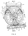
- Figures 2 and 3 are a sectional elevational view of the forming drum assembly shown in Figure 2 taken along line 3-3 thereof.
- the specific structural elements shown in Figures 2 and 3 are numbered correspondingly with respect to the features shown in Figure 1.
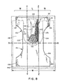
- the forming drum assembly of this embodiment comprises a drum which rotates about a series of stationary baffle members which present to the foraminous forming surface, a plurality of differential pressure zones.
- the drive shaft 19 for the forming drum is driven in the rotational direction indicated by Arrow H by forming drum drive means 52 coupled thereto by motive power transfer means 51, which in operation may constitute a gear drive, direct shaft coupling or other suitable means.
- the forming drum drive shaft 19 is disposed in a journal bearing 53 which in turn is associated with a journal bearing support member 54 to provide a support structure for the forming drum in operation.
- the inner housing of the forming drum includes a spindle 69 which is cylindrically concentric with the drive shaft 19 and has associated therewith spindle seals 70 which provide for pressure sealing between the front and rear lateral vacuum passages 94 and 95 and the central vacuum duct passage 93, during rotation.
- the drive shaft 19 is coupled to and terminates in a forming drum drive shaft spindle section 19a, which is associated with shaft seal bearings 71a and 71b and optionally with seal rings, in a manner known in the art.
- the forming drum assembly includes a stationary front wall 73a and a rotatable rear drum wall 74.
- the drive shaft 19 is secured to the rear drum wall 74 by means of a bushing and mounting assembly 75, of conventional type.
- the pressure differentials imposed on the foraminous forming surface 21 are generated by means of a vacuum source (suction) means 58, such as an exhaust fan, which is coupled to the forming drum structure via vacuum transfer coupling means 59 to the air discharge (suction) duct 23.
- a vacuum source (suction) means 58 such as an exhaust fan
- Duct 23 has associated therewith a damper assembly 60 comprising damper plate 61, and damper modulating adjustment means 62, which may be employed to manually or automatically adjust the position of the damper plate, within the annular passage as shown, both above and below the forming drum central vacuum duct 77.
- the forming drum as shown in Figures 2 and 3, comprises a central vacuum duct 93, the walls 77a, 77b of which at their upper ends mate with a closure flange 78, with sealing means 79 provided by radially overlapping ends of the closure flange 78 and the upper walls 77a, 77b.
- the forming drum as shown in Figure 2 features a series of circumferentially spaced-apart drum wall covers 90 for entry and maintenance of the interior space and apparatus of the forming drum assembly.
- the interior space of the forming drum 18 comprises a high vacuum forming zone 93 which is in the form of an arcuate segment between the duct wall baffle 102 and the duct wall baffle 103, which are shown as radially extending, imperforate plates.
- Circumferentially and axially adjacent to the high vacuum forming zone 93 is low vacuum pressure zone 92, 94, 95 located between chamber wall baffle 104 and chamber wall baffle 101.
- This low pressure zone also extends between axially spaced-apart vacuum chamber walls 73a and 77a and between chamber walls 77b and 73b at zones 94 and 95, respectively.
- high vacuum zone 93 is nested within and, in the shown embodiment, is surrounded on four sides by the low vacuum zone.
- an optional pressure blow-off zone 100 which receives air under pressure (from a source not shown, but which may suitably be an exhaust stream from the vacuum suction blower fan), and serves the function of imparting an air flow, under positive pressure differential from the interior to the exterior side of the forming surface 21, to assist in removal of the laid fibrous web 24.
- the chamber wall baffle 96 is sealed in place to the inner drum ring 99 by a seal bracket 97.
- the inner drum ring 99 as shown in Figures 2 and 3, has a plurality of openings 105 ( Figure 3) for accommodating the gas flows into, and out of, the forming drum.
- the inner drum ring 99 rotates in operation concurrent with the forming surface 21, to which same is attached.
- the inner drum ring nonetheless defines an interior region of the forming drum, which is sealed against the front and rear vacuum chamber walls 73a and 73b by closure flanges and seals analogous to flange 78 and seal 79 (as shown in Figure 3).
- Between chamber wall baffle 96 and chamber wall baffle 101 is a third vacuum zone 107, and between chamber wall baffle 101 and duct wall baffle 102 is a low vacuum, passage region through which air is drawn from the scarfing zone constituted by scarfing roll assembly 35.
- a discrete amount of vacuum should be maintained within the third vacuum zone 107 and within the low vacuum, passage to retain the fibrous web against the foraminous forming surface 21. The discrete vacuum within these regions holds web 24 on the forming drum while the rotation of the drum transports the web toward conveyor 28.
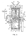
- web forming assembly 21 is distinctively configured in multiple layers to efficiently produce a laid-fibrous web.
- the outermost portion of web forming assembly 21 is comprised of a foraminous web forming layer 122 upon which the fibers of web material are deposited.
- a foraminous spacing means such as one comprised of spacing members 120 and 121, is located downstream from web forming layer 122 in an adjacent, radially inward position to support the web forming layer.
- a foraminous gas flow regulating layer 135 is in turn located downstream from and adjacent to the spacing means to provide a selected pattern of gas flow through web forming layer 122.
- the regulating or attenuating layer 135 is positioned in closely spaced registration with, and transverse to flow of gas through the forming surface to diminish the pressure differential exerted on the forming surface in register with the vacuum attenuating plate.
- the forming surface is thus made up of a series of circumferentially extending and radially adjacent elements. In the aggregate, these elements form an air-laid web forming path having a width W (Fig. 6A) and extending around the entire peripheral cylindrical surface of the forming drum.
- the web forming assembly can advantageously be configured to produce a web having a greater basis weight of fibrous material in selected medial portions than in its marginal edge portions.
- Figs. 5 and 6A illustrate an embodiment of the invention in which the web forming assembly includes at least one pocket recess 22 for forming a higher basis weight, medial portion in web 24.
- the foraminous web forming assembly 21 includes a plurality of circumferentially spaced-apart, centrally (in the cross-machine direction) aligned, concavely contoured surface portions (pocket recesses) 22 formed thereon.
- concavely contoured surface portions 22 are bounded by longitudinal side wall members 65a, transverse end wall members 65b, and a generally planar base wall member 66 which is disposed at least approximately parallel to the plane of the adjacent portion of foraminous forming assembly 21.
- the longitudinal side wall members 65a and transverse end wall members 65b are angularly oriented with respect to the plane of the forming assembly 21 proximally adjacent the concavely contoured surface portion 22, to define an included angle therebetween of not more than about 70°. Preferably this included angle is from about 45° to 68°.
- the included angle between respective longitudinal side wall members 65a and the plane P of the portion of forming assembly 21 which is proximally adjacent thereto is measured by the angle p in Figure 6C.
- the included angle between respective transverse end wall members 65b and the plane P of the portion of forming surface proximally adjacent thereto is measured by the angle ⁇ in Figure 6D.
- the side wall angle, 0, is measured between the side wall surface (extending by straight line 80 in Figure 6C) and the plane P of the forming surface proximally adjacent the concavely contoured surface portion 22.
- forming surface proximally adjacent the concavely contoured surface portion refers to the surface portion of assembly 21 that is adjacent to the concavely contoured surface portion 22 but is not in any way deformed as part of or an extension of the contour of the concave surface portion 22.
- concavely contoured as used in such context refers to the fact that the forming surface has a depression therein which under air-laying fiber deposition conditions will result in the formation of a protrusional area on the air-laid fibrous web.
- the end wall member 65D has an angle of orientation, ⁇ , which is measured between the end wall member 65b (extending by straight line 82) and the plane P of the forming surface proximally adjacent the concavely contoured surface portion.
- the angles ⁇ and p may be, but need not be, identical. For example, good releasability characteristics have been obtained in practice where the angle ⁇ is approximately 65° and the angle o( is approximately 45°, with the concavely contoured surface portion 22 being of generally inverted frusto-pyramidal shaped.
- concavely contoured surface portion may be employed to good advantage, other than the generally inverted frusto-pyramidal shape of elongate form which is shown in the illustrative drawings.
- conical or oblate conical openings could be employed, in addition to any other wall shapes and orientations meeting the side wall angle criteria hereof.
- the concavely contoured surface portion 22 is elongate in shape and its bounding walls comprise longitudinal side wall members 65a and transverse end wall members 65b joined at their bottom edges to a base wall member 66
- the included angles P of the longitudinal side walls 65a are between about 55° and 68° and the included angles ⁇ of the transverse end walls 65b are between about 45° and 60°.
- web forming layer 122 is, for example, comprised of a metallic wire screen mesh formed with a substantially square or rectangular grid pattern.
- the wire size of the mesh is about 33 gauge (about 0.03cm in diameter), and the openings 8 between the wires measure about 0.05cm across.
- the wire size and opening sizes can be varied as desired. However, the openings should not be so small that they become plugged by fibers and excessively restrict the air flow therethrough. Neither should the openings be so large that they allow excessive amounts of fibers to pass through the screen and delay the formation of web 24.
- web forming layer 122 optionally includes at least one pocket recess 22 formed therein.
- Pocket recess 22 allows an accumulation of a greater basis weight of fiber material in a restricted medial portion of web 24.
- pocket 22 advantageously allows a generally sideways gas flow through the side walls of the pocket to increase the rate of accumulation of the fiber material within the pocket.
- a plurality of substantially regularly spaced pocket recesses are formed along the circumferential length of web forming layer 122.
- the embodiment of the foraminous spacing means shown in Fig. 4 is, for example, comprised of hardware cloth 121 and spacer sheet member 120.
- Hardware cloth 121 is a coarse wire mesh formed with a generally square or rectangular grid pattern.
- the wire size is about 18 gauge (about 0.12cm diameter) and openings 29 between the consecutive wires measure about 1.15cm across.
- Hardware cloth 121 positions web forming layer 122 away from spacer sheet member 120 by a discrete distance while allowing a substantially unrestricted and substantially uniform flow of air from web forming layer 122, around and through the wire structure of hardware cloth 121 and then into spacer sheet member 120.
- the generally circular cross-section of the wire minimizes the contact area between web forming layer 122 and hardware cloth 121.
- the rounded cross-section of the wire minimizes the contact area between hardware cloth 121 and spacer sheet member 120. This very small contact area with hardware cloth 121 prevents excessive restriction of the gas flow from web forming layer 122 into spacer sheet member 120. Hardware cloth 121 also helps to support web forming layer 122 and reduce distortions thereof.
- hardware cloth 121 has a contoured spacer pocket 124 formed therein.
- Spacer pocket 124 is configured and sized to accommodate the placement of forming pocket 22 therein and to help support the mesh material employed to construct the forming pocket.
- the resultant support provided by spacer pocket 124 in hardware cloth 121 helps to reduce distortions of forming pocket 22 in forming layer 122.
- Spacer sheet member 120 is constructed from a substantially rigid sheet of material, such as metal, which is about 0.3cm thick.
- the spacer sheet member is suitably contoured to conform to the cylindrical shape of forming drum 18, and has a plurality of openings 129-132 formed therethrough to allow a substantially unrestricted air flow from hardware cloth 121. These openings range from about 0.6 - 6.4cm in diameter. In the shown embodiment, larger openings 129 measure about 5.8cm in diameter and smaller openings 130-132, which are located intermediate the regions defined by the large openings, measure about 0.6 - 2.6cm in diameter.
- spacer sheet member 120 has a cut-out opening 134 which is configured to accommodate placement of forming pocket 22 and spacer pocket 124 therethrough.
- gas flow regulating layer 135 contacts the side of spacer sheet member 120 located opposite to the side contacted by hardware cloth 121.
- Regulating layer 135 is comprised of a foraminous layer composed of a suitable material such as sheet steel.
- the regulating layer has a selected pattern of openings formed therethrough to produce a predetermined pattern of gas flow through web forming layer 122.
- regulating layer 135 has a selectively contoured portion 137 which is configured to skirt around the marginal boundary of forming pocket 22.
- the vacuum attenuating plate can have an opening or hole therethrough which is sized and configured to accommodate the placement of the concavely contoured surface portion therein.
- the vacuum attenuating plate may, as shown in Figure 6A, be generally U-shaped with its inner edge circumjacent to bounding walls of the concavely contoured surface portion.
- regulator layer 135 has regulator openings 136 which can be selectively configured and varied. More particularly, regulating layer 135 can have larger size openings in those selected areas or zones wherein a greater basis weight of fiber material is to be deposited on web forming layer 122. Similarly, regulating layer 135 can have smaller sized openings in those regions wherein a lower basis weight of material is to be deposited on the web forming layer (Fig. 6A). In an alternate configuration, the openings through regulating layer 135 can all be substantially of the same size. A greater density of openings would be located in those selected regions where a greater basis weight of fiber material is to be deposited (Fig 6B). A combination of these two techniques may also be employed.
- web forming assembly 21 The component elements of web forming assembly 21 are preferably assembled and held together by suitable fastening means.
- web forming layer 122 can be soldered to hardware cloth 121, and the hardware cloth may be spot welded to spacer sheet member 120.
- web forming assembly 21 is suitably constructed and arranged to be fit upon drum 18.
- web forming assembly 21 can be configured as a plurality of assembly segments 21a, which are sequentially and adjacently placed along the circumferential periphery of forming drum 18.
- the individual assembly segments are readily installed and replaced from the outside, upstream region of drum 18, and as a result, the web forming assembly can be quickly reconfigured to produce a variety of article types.
- the web forming assembly of the invention can be efficiently reconfigured to produce absorbent pads having different basis weight contours or different sizes by removing one set of segments 21a and replacing them with another, differently configured set of segments.
- the web forming assembly is connected to forming drum 18 by suitable fastening means.
- web forming assembly 21 rests on drum flange members 140 which position and support the web forming assembly relative to chamber wall 73a and drum side wall 74.
- Flange members 140 are fixedly mounted relative to drum side wall 74 and extend circumferentially around the drum.
- Holding means such as screws and retainer (blocking) rings 39, hold web forming assembly 21 substantially fixed against drum flange members 140.
- the embodiment of the invention shown in Figures 1-3 includes a rotatable cylindrical drum the outer circumferential wall surface of which comprises the web forming assembly.
- a plurality of concavely contoured forming surface portions 22 are circumferentially spaced apart thereon, and a plurality of radially extending, stationary baffles and walls are disposed in the interior of the rotatable cylindrical drum. These walls and baffles divide the interior into plural arcuate segments which communicate with respective differential pressure zones on the forming surface.
- a pneumatic flow means defines pressure differential zones on the forming surface and imposes a pressure differential thereon.
- the pneumatic flow means comprises a vacuum suction means joined in gas flow communication with a first arcuate segment in the cylindrical drum.
- the first arcuate segment defines a vacuum laydown zone on the forming surface
- the vacuum suction means draws air through the vacuum laydown zone on the forming surface, into the first arcuate segment and out of the rotatable cylindrical drum.
- Such apparatus can further comprise means for diverting a portion of the flow of air drawn through the vacuum laydown zone on the forming surface into the first arcuate segment, under positive pressure into a second arcuate segment defining a pressurized take-off zone for removal of the laid fibrous article from the forming surface.
- the walls 77a, 77b bound the generally wedge shaped, central duct 91, which forms the high vacuum forming zone 93 constituting an arcuate segment of the rotatable cylindrical drum.
- the walls are of arcuate shape and are disposed in transversely spaced relationship to one another to divide the first arcuate segment into transverse subsegments 94, 93 and 95 defining corresponding vacuum laydown subzones on the forming surface.
- Flow restriction means comprised on the damper assembly 60 is interposed between the vacuum suction means 58 and the two outer vacuum laydown subzones of the forming surface, 94 and 95, for effecting a transversely varying differential pressure on the forming surface vacuum laydown zone, whereby the laid fibrous article has a transversely varying basis weight (i.e., in the cross-machine direction).
- flow restriction means may be associated with the central gas flow passage to provide a reduced longitudinally extending central basis weight region relative to the outer longitudinally extending regions of the fibrous web corresponding to the peripheral gas flow passages.
- the flow restriction means in the form of a damper assembly 60 have been disposed between the transversely outer forming surface laydown subzones and the vacuum suction means.
- the air-laid fibrous web is formed from a stream of air-entrained fiberized fibers, by flow of the entrainment gas through the openings in the foraminous forming assembly 21 and into the chambers constituting the vacuum forming zones 92-95 in the rotatable drum 18. Suction is also applied to the resulting laid fibrous web in the vicinity of a scarfing zone defined by the scarfing roll assembly 35 and the scarfing housing 36.
- chamber wall member 101 is selectively moveable within forming drum 18 along the circumferential direction thereof.
- the movement of wall member 101 can advantageously be employed to regulate the amount of vacuum applied to the drum-side surface of the portion of fibrous web 24 which is located in the scarfing zone under housing 36.
- a clockwise repositioning of wall member 101 would decrease the amount of vacuum applied to the fibrous web, and a counter-clockwise repositioning of the wall member would increase the amount of vacuum applied to the fibrous web. If an excessive amount of vacuum is applied to the portion of web 24 within the scarfing zone, the fibrous material trimmed away by the scarfing roll can be redeposited onto the web instead of being withdrawn out of housing 36.
- blowoff zone 100 air is introduced under pressure and directed radially outwardly against the fibrous web on the forming surface portion circumferentially aligned therewith, whereby the gas pressure and the specifically contoured surface portion 22 effects a ready release of the fibrous web from the forming surface, without binding or sticking of the air-laid fibrous web in the depressions 22, such as would adversely impact the normal operation of the apparatus, and potentially necessitate shut-down and manual removal of the fibrous web from the forming surface.
- a vacuum suction box 116 can be located below conveyor belt 28 to help remove web 24 from the forming surface 21.
- Vacuum box 116 opens onto belt 28, and a suction of air out of the vacuum box through outlet opening 118 draws an air flow through perforations in the conveyor belt. This flow of air, in turn, operates to draw web 24 away from the forming surface. Vacuum box 116 can be employed with or without the use of positive pressure in blowoff zone 100.
- the annular space between the inner ring 99 and the forming surface 21 is circumferentially sealed by various circumferentially spaced, radially sealing members to preserve the pressure differentials in the various differential pressure zones of the forming assembly. More particularly, a plurality of transverse sealing members 110 connect in sealing engagement between inner ring 99 and forming surface 21, and also connect in sealing engagement between drum walls 73a and 74. These transverse sealing members substantially prevent the movement of ambient air through the annular space between inner ring 99 and forming surface 21 and into the low and high vacuum zones.
- circumferential sealing members 112 can optionally be located in the annular space between inner ring 99 and forming surface 21. Pairs of sealing members 112 are axially spaced apart and are located adjacent to both longitudinal side wall members of the contoured surface depressions 22. The circumferential sealing members connect in sealing engagement with transverse sealing members 110 and operate to reduce cross flow between the high vacuum zone and the low vacuum zone along a path through the annular space.
- sealing flange members 114 are connected to chamber wall baffles 101 and 104, and are arranged to contact inner ring 99 with a slideable, sealing engagement.
- Flange members 114 extend axially across the width dimensions of chamber wall baffles 101 and 104, and have a circumferentially extending length dimensions which are at least equal to the circumferential distance between consecutive transverse sealing members 110.
- the above-mentioned length dimensions refer to the portions of flange members 114 that slideably contact ring 99.
- the slideable portions of flange members 114 are arranged to extend circumferentially away from housing 11.
- flange members 114 substantially prevent the intrusion of ambient air along a path that extends through ring 99, around the edge of transverse sealing member 110, back through ring 99, around the edge of chamber wall baffle 101 or 104, and back again through ring 99 into the vacuum zones.
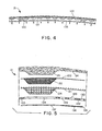
- Figure 8 shows a plan view of a laid fibrous article, which is formed by the apparatus illustrated in Figures 1-5.
- This fibrous article is particularly suitable for use in a disposable diaper.
- the air-laid article is shown in the drawing as referenced to the width W of the air-laid web forming path 140 and the vacuum regulating layer 135, the profiles of which are shown in dotted line representation for ease of reference.
- the air-laid fibrous web article 150 is shown with a lateral center line X-X, and is formed from the longitudinally extending web 24 as shown in Figure 1, by severing the web 24 transversely into suitable lengths, as described hereinafter in greater detail.
- the fibrous web article 150 has a rear section 151, posterior to the center line X-X and a front section 152 anterior thereto. As mentioned previously this fibrous web article features leg cut-outs defined by edges 153, 154, resulting from the utilization of the arcuate blocking plates 40 as shown in Figure 1.
- the key notch 26 formed by the non-flow region associated with blocking plate 39 in Figure 1 is located at a side edge of the front section of the fibrous web article; an alternative position for the open area is shown at 26'.
- Such notch or "key” can be employed as a reference point for severing the longitudinally extending fibrous web into lengths of predetermined dimension.
- the longitudinal central zone L of the fibrous web article provides a higher basis weight region of the article relative to zones M and N on either side thereof.
- the respective lines Y and Z demarcating the successive longitudinal zones define the general, approximate locations of fold-lines, along which the fibrous web article may be folded for storage and packaging purposes.
- the longitudinal peripheral zones correspond to the outer forming surface subzones overlying vacuum passages 94 and 95 as shown in Figure 8, with the central longitudinal zone L corresponding to vacuum passage 93 in Figure 8.
- Each of the longitudinal peripheral zones M, N has associated therewith laterally extending corner segments or "ears" with the front section 152 having left-hand and right-hand ears, 157 and 158 respectively, with rear section 151 having associated therewith corresponding ears 159 and 160.
- an integral pad 25 Positioned in the central longitudinal zone L of the front section 152 is an integral pad 25, corresponding to the protrusion formed on the longitudinal extending web in the operation of the apparatus shown in Figures 1-5.
- Pad 25 comprises a frusto-pyramidal, nonseparable protrusion from the fibrous article's top surface, corresponding to the concavely contoured surface portion of the forming surface.
- Pad 25 features a pad top surface 165 which is radiused and corresponds to the base wall member 66 of the forming surface 21.
- the pad side surfaces 166 and 167 correspond to the side walls of the concavely contoured surface portion, and the pad end surfaces 168, 169 correspond to the end wall members of the concavely contoured forming surface portion.
- a high basis weight region 175 extends transversely across the longitudinal zones M, L and N generally in the front section of the fibrous web article, and its boundary is demarcated by and corresponds to the edge 137 of the vacuum blocking plate 135, whereby the basis weight of the material surrounding pad 25 is higher than the ear regions 157, 158 in the front section of the fibrous article and is higher than the basis weight of the rear section 151 of the fibrous article, with the exception of the small arcuate segment extending centrally longitudinally for a short distance posterior of the lateral center line X-X.
- the vacuum laydown zone has subzones which are situated and arranged to provide a lower pressure differential in the peripheral forming surface subzones defined by vacuum passages 94, 95 relative to the central subzone 93, and the blocking plate is configured to provide approximately 65% of the weight of the fibrous article in the front section 152 of the laid article and approximately 35% of the weight in the rear section 151 thereof.
- a fibrous article is highly advantageous in disposable diaper service.
- discrete fibrous articles can be directly formed on forming assembly 21.
- a plurality of blocking bar members 111 can be located at selected locations along the circumference of the forming surface. Bar members 111 interconnect between blocking rings 39 and are generally aligned along the axial dimension of forming drum 15. These bar members also overlie forming surface 21 and block the accumulation of fibers along relatively narrow, transverse portions of the forming surface. As a result, the deposition of fibers onto forming surface 21 can create a substantially non-continuous web comprised of individual, discrete fibrous articles.
- fiber forming chamber 11 includes fiber directing means, such as baffle plates 144 which steer and direct fibers toward the middle portion of web forming assembly 21, as representatively shown in Fig. 3.
- fiber directing means such as baffle plates 144 which steer and direct fibers toward the middle portion of web forming assembly 21, as representatively shown in Fig. 3.
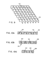
- the spacing member can alternatively be comprised of a sheet-like grid 146, such as a honeycomb type grid or a grid with other polygonal patterns or curvilinear patterns.
- grid sheet member 146 is sufficiently deformable to follow the curvilinear path of a forming drum or of a endless forming belt.
- the sheet structure of grid 146 would have sufficient thickness to suitably space web forming layer 122 at a operable distance from regulating layer 135.
- the edges of the grid elements which contact web forming layer 122 would be suitably rounded or otherwise contoured to allow a substantially unrestricted gas flow into the grid structure from the region immediately adjacent to and downstream from the web forming layer.
- These grid elements would define a plurality of individual conduit cells 147 that would direct air flow from web forming layer 122 to regulating layer 135 and would substantially span across the distance between the web forming layer and the regulating layer.
- the flow regulating layer can be comprised of a sheet-like member 148 which has a plurality of selectively "tapered" openings formed therethrough.
- tapered holes are illustrated in Figs. 10A-C, and may be formed with suitably contoured machining or drilling tools. For example, a sequence of drills having increasing diameters can be employed to form a stepped hole, as representatively shown in Fig. 10B. This stepped hole 150 can provide an effective tapered opening.
- Sheet layer 148 can, for example, be combined with a suitable hardware cloth spacing means to allow a substantially unrestricted gas flow from the region immediately adjacent to and downstream from the associated web forming layer.
- Tapered openings or holes 152 and 154 are configured with selected diameters and angles of taper, and are arranged with the smaller sized end of the hole more proximate to the hardware cloth and with the larger sized end of the hole more distant from the hardware cloth. This arrangement can reduce plugging of the holes by the fibers of web material. Holes 152 located at regions where a greater basis weight of material is desired would have a more open taper to provide less restriction to the gas flow. In contrast, holes 154 located at regions where a lower basis weight of material is desired would have a more closed taper and would provide more restriction to the flow of gas. In this particular embodiment of the invention, sheet member 148 effectively performs the functions of both the spacing member 120 and the flow regulating layer 135 shown in Fig. 6A.
- a forming drum was constructed in accordance with Figs. 1, 2 and 3, and a web forming assembly was constructed in accordance with Figs. 5 and 6A.
- Drum 18 had a diameter of 57.85in (146.9cm) and rotated at 20rpm.
- Suction pump fan 58 drew air out from duct 92 at a rate of 4.72m 3 /sec, and fiberizer 68 provided fibrous web material at a rate of 12kg/min.
- the web material was composed of wood pulp fibers.
- Web forming layer 122 was constructed from 28x30 mesh wire screen. The wire diameter was 0.03cm and the openings through the screen measured 0.05cm across.
- Hardware cloth 121 was a wire screen having 1/2in (1.27cm) square mesh openings.
- the wire diameter was 0.12cm and the openings through the screen measured 1.15cm across.
- the forming pocket 22 had a generally frusto-pyramidal shape that was 4.7cm deep and measured 19cm x 8.98cm at its base.
- Spacer pocket 124 has a shape similar to that of forming pocket 22 but was suitably sized to accommodate the placement of the forming pocket therein.
- Spacer sheet member 120 was fabricated from sheet steel and was 0.3cm thick.
- the large holes 129 measured 5.56cm in diameter and were substantially uniformly distributed across the surface of the sheet member. Smaller holes 130 and 132 were located in the areas between the large holes. Holes 130 measured 2.6cm in diameter and holes 132 measured 0.95cm in diameter.
- Cut-out 137 was sized and configured to accommodate the placement of forming pocket 22 and spacer pocket 124 therethrough.
- Flow regulating layer 135 was composed of 24 gauge stainless steel sheet, and had an edge 137 which was configured to skirt around the region of forming pocket 22.
- Regulating holes 136 formed through the regulating layer measured 0.31cm in diameter and were distributed across the layer in a straight centered pattern.
- the apparatus was employed to form a fibrous web 24 which had an alternating pattern of high basis weight zones and low basis weight zones.
- Web 24 was cut into individual pads each of which had a medial portion with a basis weight of 0.16g/cm 2 and edge portions with a basis weight of 0.03g/cm 2 . These pads were employed in the manufacture of disposable diapers for infants.
Abstract
Description
- The present invention relates to an apparatus and a method for forming fibrous webs.
- Absorbent disposable articles, such as diapers, feminine napkins and incontinence garments, employ absorbent batts to absorb body fluids, such as urine. It has generally been desirable to form a contoured batt or pad which locates more absorbent material in those areas which are subjected to higher levels of fluid loading. Various types of conventional machines have been employed to manufacture such contoured pads.
- U.S. Patent 4,388,056 issued June 14, 1983 to F. B. Lee, et al. discloses an apparatus for continuously forming a cyclically contoured and densified air-laid fibrous web. The web has alternately spaced narrow regions with relatively high basis weight and wide regions with relatively low basis weight. Adjustable shutter plates are configured to span a plurality of transverse plenum segments to modulate the air flow through the device.
- U.S. Patent 3,682,761 issued August 8, 1972 to C. A. Lee, et al. discloses a device for forming an elongated air-laid web. This web has a longitudinally extending central portion and integral longitudinally extending portions flanking the central portion. This web also has a generally stepped configuration with a greater average thickness in the central portion than in the side portions. The device taught by C. A. Lee, et al. employs baffles to direct more fibrous material toward the central portion of the web, and employs a plurality of valves to increase the amount of suction through the central portion of the web to induce the formation of a greater thickness at that central portion.
- U.S. Patent 4,005,957 issued February 1, 1977 to P. Savich discloses a device which has a screen with pockets formed therein and which is employed to manufacture fibrous pads.
- U.S. Patent 3,973,291 issued August 10, 1976 to C. G. Kolbach discloses a method and apparatus for forming discrete fibrous pads which have contoured thickness. The method and apparatus disclosed by Kolbach employ a sequence of masks which completely block off a source of applied vacuum to all sections of each pad receiving compartment except that section in which a region of a fibrous pad having a particular weight of fibers per unit area is to be formed.
- U.S. Patent 4,016,628 issued April 12, 1977 to C. C. Kolbach discloses a device for forming an air-laid fibrous web having a medial portion of greater basis weight than flanking end and side portions. The apparatus includes a vacuum box which has an open end underlying a discrete section of a foraminous forming surface. Vacuum connection means establish a greater pressure drop across the discrete section of the foraminous forming surface overlying the open end of the vacuum box than across the regions of the foraminous forming surface extending beyond the edges of the vacuum box.
- U.S. Patent 3,962,753 issued June 15, 1976 to J. W. Dunn discloses a device for forming a fibrous glass strand mat. The apparatus includes a panel having a plurality of spaced apertures located underneath a foraminous conveyor. The plate creates a back pressure and a relatively static high pressure area immediately above the conveyor. This eliminates the problem of random movement of the fibers after deposition on the conveyor, and reduces the air circulation to permit an even distribution of the fibers on the mat.
- U.S. Patent 4,103,058 issued July 25, 1978 to L. D. Humlicek discloses a blown microfiber web having a network of compacted high-density regions and pillowed low density regions. The web may be collected on a perforated screen so that the microfibers deposited on the land area of the screen form the compacted high density regions and microfibers deposited over the openings of the screen formed the pillowed low density regions.
- Conventional devices, such as those taught by the above references, have been difficult to adjust. In particular, these devices have required complicated adjustments to moveable plate elements located inside the forming mechanism, or have required complicated arrangements of compartments and multiple vacuum suction means for providing different amounts of applied suction to selected regions of a forming screen.
- It is an object of the present invention to provide an improved apparatus for forming fibrous webs. This object is solved by the apparatus described in claim 1 and independent claims 8 and 12. Further advantageous features of the apparatus are evident from the subclaims. It is a further object of this invention to provide an improved method for forming fibrous webs. This object is solved by the process as described in independent claims 6 and 16. Further advantageous features of this process are evident from the subclaims.
- The invention allows a controlled formation of light and heavy fluff zones. The invention also provides a method and an apparatus for forming an absorbent batt that has tailored absorbency zones. Certain zones or areas have a higher basis weight and a correspondingly higher absorbency than other zones.
- Generally stated, the apparatus of the invention includes a fiber supply means for providing fibers of web material. These fibers are deposited on a foraminous web forming layer, which is supported by a foraminous spacing means. The foraminous spacing means supports the web forming layer in a configuration which allows a substantially unrestricted gas flow from a region immediately adjacent to and downstream from the web forming layer. A gas flow regulating layer has a selected pattern of apertures therethrough, and is fixedly positioned in adjacent, facing relation with the foraminous spacing means to provide a selected pattern of gas flow through the web forming layer. The foraminous web forming layer, the foraminous spacing means and the gas flow regulating layer are constructed to form an installable and replaceable assembly, and flow forcing means provide a selected flow of gas through the web forming layer.
- The invention further provides a method for forming a fibrous web, which includes the step of depositing fibers of web material onto a foraminous web forming layer. The web forming layer is supported in a configuration which allows a substantially unrestricted gas flow from a region immediately adjacent to and downstream from the web forming layer. A selected pattern of gas flow is directed through the web forming layer by a gas flow regulating layer, which has a selected pattern of apertures therethrough and is fixedly positioned downstream from the web forming layer. The foraminous web forming layer, the foraminous spacing means and the gas flow regulating layer are constructed to form an installable and replaceable assembly, and a suitable flow of gas is forced through the web forming layer.
- The method and apparatus of the invention can advantageously provide a web forming assembly which includes a gas flow regulating mechanism and is readily installable on and removable from an outside portion of a transport means. The regulating mechanism is readily adjusted to produce a desired distribution of fiber basis weight across the formed web. Maintenance and set-up time can be reduced, and the forming assembly is less susceptible to clogging by the fibers.
- The invention will be more fully understood and further advantages will become apparent when reference is made to the following detailed description of the invention and the following drawings in which:
- Fig. 1 representatively shows a perspective view of a forming drum which can be employed with the method and apparatus of the invention;
- Fig. 2 representatively shows a side elevational view of the forming drum apparatus;
- Fig. 3 representatively shows a cross-sectional, end view of the forming drum;
- Fig. 4 representatively shows a detailed, cross-sectional view of the multi-layer forming assembly of the forming drum;
- Fig. 5 representatively shows an exploded, cross-sectional view of another embodiment of the multi-layer forming assembly, which includes a pocket recess;
- Figs. 6A and 6B representatively show an exploded, perspective views of the multi-layer forming assembly of the forming drum;
- Figs. 6C and 6D show cross-sectional views of a representative pocket recess;
- Fig. 7 representatively shows a forming drum having a plurality of web forming assembly segments;
- Fig. 8 shows a plan view of a representative fibrous article;
- Fig. 9 representatively shows a spacing member having a sheet-like grid configuration; and
- Figs. 10A-C representatively show flow regulating members having tapered openings formed therein.
- The method and apparatus of the present invention are particularly useful for forming contoured fibrous webs or pads which have an increased weight of material in selected regions. When forming pads of absorbent material, the regions with greater weight of material generally have a corresponding greater degree of absorbency. Such contoured absorbent pads are particularly useful in articles that are subjected to a greater fluid loading in certain "target" areas than in other areas. For example, in a baby diaper comprised of the absorbent batt or pad is located between a liquid pervious inner layer and a liquid impervious outer layer, the crotch and front areas of the diaper are more heavily wetted by the infant than the areas closer to the infant's waist or back. A similar situation may also arise in the case of wound dressings, incontinence garments and feminine sanitary napkins.
- While the following detailed description will be made in the context of the manufacture of a disposable diaper, it will be readily apparent that the method and apparatus of the present invention can be employed to produce fibrous webs or pads for other types of articles which require a greater weight of material in selected regions. Such articles would include, for example, incontinence garments, sanitary napkins and the like, all of which are contemplated as being within the scope of the invention.
- In the following description, the term "basis weight" is intended to designate the weight of fiber material per unit surface area of the web. For example, typical units would be grams/cm .
- The material employed to form the fibrous web is typically composed of an absorbent material, such as a cellulosic material commonly known as "fluff", or the like. In addition, the web material may include a coformed mixture of cellulosic fibers with polymeric fibers, such as polypropylene fibers, polyethylene fibers, or the like. The precursor web material is generally supplied in sheet form, wound into a roll.
- Referring now to the drawings, Figure 1 shows a representative apparatus suitable for forming a laid fibrous article in accordance with the present invention.
Fibers 10, which enter the system as air-entrained fibers in a stream flowing in the direction indicated by Arrow A, may suitably be derived from a supply of cellulosic, e.g., wood pulp, fibers or other natural or synthetic fibers, which have been subjected to fiberization treatment, i.e., picked apart, in a manner known in the art to provide loose fibers. The fibers may be entrained in any other suitable gaseous medium, and references to "air" as the entraining medium herein will be understood to encompass all such other entrainment fluids. - The stream of air-entrained fibers passes by means of flow channel housing 11 to the forming
drum assembly 15. The flow channel housing serves to direct and concentrate the air-entrained fibers and to provide a uniform velocity profile in the air/fibers stream. The flow channel housing is supported by support members 12a-c, which aggregately form a support frame for the housing and may be anchored and/or joined to other suitable structural elements as necessary or desirable. The fibers deposit onto an upstream surface of a replaceable, foraminousweb forming assembly 21, which is located on an outer peripheral rim section of a substantiallycylindrical drum 18. - In the present description, the terms "downstream" and "upstream" are determined with respect to the direction of gas flow produced by gas
flow forcing means 58. In the shown embodiments, this gas flow direction is generally from top to bottom and from the outside ofdrum 18 to the inside of the drum. With respect to a particular reference point or location, "upstream" refers to an orientation in which the gas stream is approaching the reference location, and "downstream" refers to an orientation in which the gas stream is departing from the reference location. Thus, for example, the upstream surface ofweb forming assembly 21 is an outwardly facing surface, and the downstream surface of the assembly is an inwardly facing surface. - As representatively shown in Figs. 4 and 5,
web forming assembly 21 includes a foraminousweb forming layer 122, which has anoptional pocket recess 22 formed therein and which receives a deposit of the fibers of web material thereon. A foraminous spacing means, such as one comprised ofhardware cloth 121 andspacer sheet member 120, supportsweb forming layer 122 while allowing a substantially unrestricted gas flow from a region immediately adjacent to and downstream from the web forming layer. A gasflow regulating layer 135 has a selected pattern of apertures therethrough and is fixedly positioned in adjacent, facing relation with the foraminous spacing means. This flow regulating layer provides a selected pattern of gas flow throughweb forming layer 122. The combination of the web forming assembly, the foraminous spacing means and the gas flow regulating layer provides a web forming assembly, which as a unit can be replaceably mounted on a selected transport means. - Referring again to Fig. 1, a transport means, such as
rotatable drum assembly 15, moves multi-layerweb forming assembly 21 along a path which traverses through fiber forming chamber 11. Alternatively, the transport means may be comprised of a moveable, endless belt or conveyor, such as representatively shown in U.S. Patent 3,973,291. - Gas flow forcing means 58, such as a suction pump fan, draws air out from suction chambers formed within
drum assembly 15 by way ofconduit 23. As a result, the pump fan creates a pressure differential across multi-layerweb forming assembly 21 between the suction chambers and fiber forming chamber 11. This pressure differential, which can range from about 15 - 25 inches water (about 3.74 - 6.22 kPa), draws the fibers from chamber 11 onto that portion of the surface ofweb forming assembly 21 located within the boundary confines of the fiber forming chamber. - As representatively shown in Figs. 2 and 3,
drum assembly 15 rotates aboutshaft 19 to carryweb forming assembly 21 through fiber forming chamber 11 and to carry formedweb 24 out from chamber 11 to a shaping means, such as scarfingroll 37. Scarfingroll 37 rotates about a shaft and contacts the radially outwardly facing free surface ofweb 24. The movement of the peripheral surface of scarfingroll 37 removes uneven spots from the free surface ofweb 24 to produce a more uniform and level outer surface on the web. A further rotation ofdrum 18 carriesweb 24 around to conveyor means 27. This conveyor is generally comprised of a flexible screen mesh in the form of an endless belt that moves around a path defined by guide rollers. The guide rollers are driven by suitable drive means, such as an electric motor (not shown) to transportweb 24 to a desired location.Web 24 generally detaches itself fromweb forming assembly 21 by reason of its own weight and drops ontoconveyor 27. Optionally, a selected gas pressure can be applied to help removeweb 24 fromweb forming assembly 21 anddrum assembly 15. - The forming
drum assembly 15 comprises a formingdrum 18 which is rotatable in the direction of Arrow B. Rotation of the drum is affected by means of the formingdrum drive shaft 19 which may be joined to suitable drive means (not shown) such as an electric or other motor directly or indirectly coupled to such shaft. The forming drum comprises an air-laid fibrousweb laydown zone 20 positioned beneath the air/fibers flow channel housing 11 and configured as a vacuum laydown zone of the foraminous,web forming assembly 21. This vacuum laydown zone constitutes a circumferential cylindrical surface portion of the rotatable drum. The vacuum laydown surface has imposed thereon a pressure differential under the action of vacuum suction means (not shown), such as an exhaust blower or other suitable suction means, which suctioningly withdraws air from the arcuate segment of the forming drum associated with the vacuum laydown surface through the air discharge (suction)duct 23, in a manner more fully described hereinafter. The foraminousweb forming assembly 21 can optionally have therein a series of circumferentially spaced-apart, inverted, generally frusto-pyramidal shaped depressions or pockets provided by contouredsurface portions 22 in the surface thereof, of elongate form with their longitudinal axes coincident with the center line of theweb forming assembly 21, i.e., thesurface portions 22 are typically centered on the forming surface relative to the cross-machine direction. - As described more fully hereinafter, the forming drum contains a series of radially extending wall members or baffles 101, 102, 103, 104, 98 and 96, which are stationary, as described more fully in connection with Figures 2 and 3 herein.
- Thus, under the influence of vacuum suction means, air in the air-entrained fibers stream is drawn through the
web forming assembly 21 into the interior of the forming drum, betweenbaffle plate members discharge duct 23 in the direction of Arrow C. As the air-entrained fibers stream impinges on theweb forming assembly 21, only the air component thereof is passed through and the fibers component of the stream is retained on the forming surface to form a nonwoven fibrous web thereon. Subsequently, with rotation of the drum, the formedweb 24 is removed from the forming surface under the influence of gravity by the weight of thefibrous web 24 and with a pressure differential produced, for example, by pressurized air in blow-off zone '100, betweenbaffle plate members off zone 100, combined with the weight of thefibrous web 24 and the conformation of the contoured surface portions (depressions) 22, as hereinafter described, results in a readily removed fibrous web. - The
web 24 is removed from the forming surface onto take-offconveyor 27 comprisingendless conveyor belt 28 disposed aboutrollers roller shaft members conveyor 27 features apad 25 corresponding to the concavely contouredsurface portions 22 on the forming surface. - In addition to the blocking plate rings 39, the forming surface may also have disposed thereon symmetrically opposed
arcuate blocking plates 40, as shown. These blocking plates are particularly advantageous when the forming drum assembly is employed to produce absorbent webs for use in disposable diapers and the like, whereby the blockingplates 40 prevent deposition of fibers on the forming surface to form corresponding arcuate cut-out sections on the finished web (not shown in Figure 1, but as indicated in Figure 8 by the edges 153, 154). - The longitudinally extending
fibrous web 24 prior to its removal from the forming drum passes through the scarfing zone defined by the scarfingroll assembly 35. The scarfing roll assembly in turn comprises scarfingroll housing 36 containing scarfingroll 37 disposed on a scarfingroller shaft member 38, driven by means which for simplicity are not shown, but which may be any suitable motive means, and for example may involve coupling by gear or other means to the motor or drive means for therotatable drum 18. The scarfing roll assembly constitutes trimming means for trimming the excess radial thickness of the laid fibrous web deposited on theweb forming assembly 21 to yield a laid fibrous web having a substantially uniform, flat cross-direction contour on one major face surface thereof. The scarfingroll 37 is disposed in spaced adjacent relationship to the forming surface, and the scarfing roll and the forming surface are translated relative to one another in opposite directions, to remove excess thickness of the fibrous web. A transporting means, such as a suction fan, (not shown) draws the removed fibrous material away from the formed fibrous web and out from scarfinghousing 36. - Thus, in the apparatus as shown in Figure 1, the forming drum rotates in the direction shown by Arrow B, and the scarfing
roll 37 moves in the same direction of rotation, thereby providing opposed movement of the roller surface relative to the surface of the drum proximate thereto, to remove excess thickness of the laid fibrous web. Alternatively scarfingroll 37 can be rotated to provide a co-directional movement of the roller surface relative to the surface of the forming drum most proximate thereto. In either situation, the rotational speed of scarfingroll 37 should be suitably selected to provide an effective scarfing and leveling action against the contacting surface of the formed fibrous web. In like manner, any other suitable means may be employed in place of the scarfingroll assembly 35 to provide a cutting or abrading action to the laid fibrous web by relative movement between the web (forming surface) and the trimming means. -
Web forming assembly 21 constitutes the outer cylindrical surface of the formingdrum 18 and features a non-flow region of the foraminous forming surface which may suitably be formed by blockingplate ring 39 or other suitable means that occludes the flow of gas through the forming surface. Such occlusion serves to prevent laydown of fibers on the edges of the forming surface when the stream of air-entrained fiberized fibers is flowed thereon with passage of the entraining gas therethrough. Acontoured blocking ring 39 can be configured to form akey notches 26 on the finished laid fibrous web to provide sensing point for severing of the longitudinally extending fibrous web into discrete air-laid fibrous articles. Reference has been made in the preceding sentence to a longitudinally extending character of thefibrous web 24, and this will be understood to refer to the dimension or axis of the web in the direction indicated by Arrow D, whereby the longitudinal dimension is at right angles to the transverse or lateral dimension of the web (the lateral direction hereinafter being referred to also as the cross-machine direction, in contrast to the machine direction, which is the longitudinal direction). - The details of structure of the forming
drum 18 are shown in Figures 2 and 3, Figure 3 being a sectional elevational view of the forming drum assembly shown in Figure 2 taken along line 3-3 thereof. The specific structural elements shown in Figures 2 and 3 are numbered correspondingly with respect to the features shown in Figure 1. - The forming drum assembly of this embodiment comprises a drum which rotates about a series of stationary baffle members which present to the foraminous forming surface, a plurality of differential pressure zones.
- As shown in Figure 3, the
drive shaft 19 for the forming drum is driven in the rotational direction indicated by Arrow H by forming drum drive means 52 coupled thereto by motive power transfer means 51, which in operation may constitute a gear drive, direct shaft coupling or other suitable means. The formingdrum drive shaft 19 is disposed in a journal bearing 53 which in turn is associated with a journal bearingsupport member 54 to provide a support structure for the forming drum in operation. - The inner housing of the forming drum includes a
spindle 69 which is cylindrically concentric with thedrive shaft 19 and has associated therewith spindle seals 70 which provide for pressure sealing between the front and rearlateral vacuum passages drive shaft 19 is coupled to and terminates in a forming drum drive shaft spindle section 19a, which is associated with shaft seal bearings 71a and 71b and optionally with seal rings, in a manner known in the art. The forming drum assembly includes a stationaryfront wall 73a and a rotatable rear drum wall 74. Thedrive shaft 19 is secured to the rear drum wall 74 by means of a bushing and mountingassembly 75, of conventional type. - The pressure differentials imposed on the foraminous forming
surface 21 are generated by means of a vacuum source (suction) means 58, such as an exhaust fan, which is coupled to the forming drum structure via vacuum transfer coupling means 59 to the air discharge (suction)duct 23.Duct 23 has associated therewith adamper assembly 60 comprisingdamper plate 61, and damper modulating adjustment means 62, which may be employed to manually or automatically adjust the position of the damper plate, within the annular passage as shown, both above and below the forming drumcentral vacuum duct 77. - The forming drum, as shown in Figures 2 and 3, comprises a central vacuum duct 93, the
walls 77a, 77b of which at their upper ends mate with aclosure flange 78, with sealing means 79 provided by radially overlapping ends of theclosure flange 78 and theupper walls 77a, 77b. The forming drum as shown in Figure 2 features a series of circumferentially spaced-apart drum wall covers 90 for entry and maintenance of the interior space and apparatus of the forming drum assembly. - The interior space of the forming
drum 18 comprises a high vacuum forming zone 93 which is in the form of an arcuate segment between theduct wall baffle 102 and theduct wall baffle 103, which are shown as radially extending, imperforate plates. Circumferentially and axially adjacent to the high vacuum forming zone 93 is lowvacuum pressure zone chamber wall baffle 104 andchamber wall baffle 101. This low pressure zone also extends between axially spaced-apartvacuum chamber walls 73a and 77a and betweenchamber walls zones - Intermediate the circumferentially spaced-apart chamber wall baffles 96 and 98 is an optional pressure blow-
off zone 100, which receives air under pressure (from a source not shown, but which may suitably be an exhaust stream from the vacuum suction blower fan), and serves the function of imparting an air flow, under positive pressure differential from the interior to the exterior side of the formingsurface 21, to assist in removal of the laidfibrous web 24. As shown, thechamber wall baffle 96 is sealed in place to theinner drum ring 99 by aseal bracket 97. Theinner drum ring 99, as shown in Figures 2 and 3, has a plurality of openings 105 (Figure 3) for accommodating the gas flows into, and out of, the forming drum. Theinner drum ring 99 rotates in operation concurrent with the formingsurface 21, to which same is attached. The inner drum ring nonetheless defines an interior region of the forming drum, which is sealed against the front and rearvacuum chamber walls flange 78 and seal 79 (as shown in Figure 3). Betweenchamber wall baffle 96 andchamber wall baffle 101 is athird vacuum zone 107, and betweenchamber wall baffle 101 andduct wall baffle 102 is a low vacuum, passage region through which air is drawn from the scarfing zone constituted by scarfingroll assembly 35. A discrete amount of vacuum should be maintained within thethird vacuum zone 107 and within the low vacuum, passage to retain the fibrous web against the foraminous formingsurface 21. The discrete vacuum within these regions holdsweb 24 on the forming drum while the rotation of the drum transports the web towardconveyor 28. - Referring to Figs. 4 and 5,
web forming assembly 21 is distinctively configured in multiple layers to efficiently produce a laid-fibrous web. The outermost portion ofweb forming assembly 21 is comprised of a foraminousweb forming layer 122 upon which the fibers of web material are deposited. A foraminous spacing means, such as one comprised of spacingmembers web forming layer 122 in an adjacent, radially inward position to support the web forming layer. A foraminous gasflow regulating layer 135 is in turn located downstream from and adjacent to the spacing means to provide a selected pattern of gas flow throughweb forming layer 122. - The regulating or attenuating
layer 135 is positioned in closely spaced registration with, and transverse to flow of gas through the forming surface to diminish the pressure differential exerted on the forming surface in register with the vacuum attenuating plate. - The forming surface, as shown, is thus made up of a series of circumferentially extending and radially adjacent elements. In the aggregate, these elements form an air-laid web forming path having a width W (Fig. 6A) and extending around the entire peripheral cylindrical surface of the forming drum. In particular aspects of the invention, the web forming assembly can advantageously be configured to produce a web having a greater basis weight of fibrous material in selected medial portions than in its marginal edge portions. For example, Figs. 5 and 6A illustrate an embodiment of the invention in which the web forming assembly includes at least one
pocket recess 22 for forming a higher basis weight, medial portion inweb 24. In the embodiment illustrated in Fig. 1 the foraminousweb forming assembly 21 includes a plurality of circumferentially spaced-apart, centrally (in the cross-machine direction) aligned, concavely contoured surface portions (pocket recesses) 22 formed thereon. - As representatively shown in Figures 6A, 6C and 6D, concavely contoured
surface portions 22 are bounded by longitudinalside wall members 65a, transverseend wall members 65b, and a generally planarbase wall member 66 which is disposed at least approximately parallel to the plane of the adjacent portion of foraminous formingassembly 21. The longitudinalside wall members 65a and transverseend wall members 65b are angularly oriented with respect to the plane of the formingassembly 21 proximally adjacent the concavely contouredsurface portion 22, to define an included angle therebetween of not more than about 70°. Preferably this included angle is from about 45° to 68°. Thus, the included angle between respective longitudinalside wall members 65a and the plane P of the portion of formingassembly 21 which is proximally adjacent thereto is measured by the angle p in Figure 6C. Similarly, the included angle between respective transverseend wall members 65b and the plane P of the portion of forming surface proximally adjacent thereto is measured by the angle α in Figure 6D. - The side wall angle, 0, is measured between the side wall surface (extending by
straight line 80 in Figure 6C) and the plane P of the forming surface proximally adjacent the concavely contouredsurface portion 22. As used herein, the term "forming surface proximally adjacent the concavely contoured surface portion" refers to the surface portion ofassembly 21 that is adjacent to the concavely contouredsurface portion 22 but is not in any way deformed as part of or an extension of the contour of theconcave surface portion 22. The term "concavely contoured" as used in such context refers to the fact that the forming surface has a depression therein which under air-laying fiber deposition conditions will result in the formation of a protrusional area on the air-laid fibrous web. In like manner, as shown in Figure 6D, the end wall member 65D has an angle of orientation, α, which is measured between theend wall member 65b (extending by straight line 82) and the plane P of the forming surface proximally adjacent the concavely contoured surface portion. - In the present invention, the wall angles α and should each be not more than about 70°, and preferably, should each be in the range of from about 45° to 68° to effect improved releasability of the fibrous web from the forming surface. The angles α and p may be, but need not be, identical. For example, good releasability characteristics have been obtained in practice where the angle β is approximately 65° and the angle o( is approximately 45°, with the concavely contoured
surface portion 22 being of generally inverted frusto-pyramidal shaped. Nonetheless, it is to be recognized that numerous other shapes and conformations for the concavely contoured surface portion may be employed to good advantage, other than the generally inverted frusto-pyramidal shape of elongate form which is shown in the illustrative drawings. For example, conical or oblate conical openings could be employed, in addition to any other wall shapes and orientations meeting the side wall angle criteria hereof. - In the specific embodiment shown in the drawings, wherein the concavely contoured
surface portion 22 is elongate in shape and its bounding walls comprise longitudinalside wall members 65a and transverseend wall members 65b joined at their bottom edges to abase wall member 66, it is preferred that the included angles P of thelongitudinal side walls 65a are between about 55° and 68° and the included angles α of thetransverse end walls 65b are between about 45° and 60°. - In a particular embodiment of the invention,
web forming layer 122 is, for example, comprised of a metallic wire screen mesh formed with a substantially square or rectangular grid pattern. The wire size of the mesh is about 33 gauge (about 0.03cm in diameter), and the openings 8 between the wires measure about 0.05cm across. The wire size and opening sizes can be varied as desired. However, the openings should not be so small that they become plugged by fibers and excessively restrict the air flow therethrough. Neither should the openings be so large that they allow excessive amounts of fibers to pass through the screen and delay the formation ofweb 24. - To provide a fibrous web having a contoured basis weight,
web forming layer 122 optionally includes at least onepocket recess 22 formed therein. (Figs. 5 and 6A)Pocket recess 22 allows an accumulation of a greater basis weight of fiber material in a restricted medial portion ofweb 24. In addition,pocket 22 advantageously allows a generally sideways gas flow through the side walls of the pocket to increase the rate of accumulation of the fiber material within the pocket. To provide an increased production rate, a plurality of substantially regularly spaced pocket recesses are formed along the circumferential length ofweb forming layer 122. - The embodiment of the foraminous spacing means shown in Fig. 4 is, for example, comprised of
hardware cloth 121 andspacer sheet member 120.Hardware cloth 121 is a coarse wire mesh formed with a generally square or rectangular grid pattern. The wire size is about 18 gauge (about 0.12cm diameter) andopenings 29 between the consecutive wires measure about 1.15cm across.Hardware cloth 121 positionsweb forming layer 122 away fromspacer sheet member 120 by a discrete distance while allowing a substantially unrestricted and substantially uniform flow of air fromweb forming layer 122, around and through the wire structure ofhardware cloth 121 and then intospacer sheet member 120. The generally circular cross-section of the wire minimizes the contact area betweenweb forming layer 122 andhardware cloth 121. Similarly, the rounded cross-section of the wire minimizes the contact area betweenhardware cloth 121 andspacer sheet member 120. This very small contact area withhardware cloth 121 prevents excessive restriction of the gas flow fromweb forming layer 122 intospacer sheet member 120.Hardware cloth 121 also helps to supportweb forming layer 122 and reduce distortions thereof. - In the particular embodiment of the invention shown in Fig. 5 and 6A,
hardware cloth 121 has a contouredspacer pocket 124 formed therein.Spacer pocket 124 is configured and sized to accommodate the placement of formingpocket 22 therein and to help support the mesh material employed to construct the forming pocket. The resultant support provided byspacer pocket 124 inhardware cloth 121 helps to reduce distortions of formingpocket 22 in forminglayer 122. -
Spacer sheet member 120 is constructed from a substantially rigid sheet of material, such as metal, which is about 0.3cm thick. The spacer sheet member is suitably contoured to conform to the cylindrical shape of formingdrum 18, and has a plurality of openings 129-132 formed therethrough to allow a substantially unrestricted air flow fromhardware cloth 121. These openings range from about 0.6 - 6.4cm in diameter. In the shown embodiment,larger openings 129 measure about 5.8cm in diameter and smaller openings 130-132, which are located intermediate the regions defined by the large openings, measure about 0.6 - 2.6cm in diameter. In addition,spacer sheet member 120 has a cut-outopening 134 which is configured to accommodate placement of formingpocket 22 andspacer pocket 124 therethrough. - In the embodiments shown in Figs. 4, 5 and 6A, gas
flow regulating layer 135 contacts the side ofspacer sheet member 120 located opposite to the side contacted byhardware cloth 121. Regulatinglayer 135 is comprised of a foraminous layer composed of a suitable material such as sheet steel. The regulating layer has a selected pattern of openings formed therethrough to produce a predetermined pattern of gas flow throughweb forming layer 122. In addition, regulatinglayer 135 has a selectively contouredportion 137 which is configured to skirt around the marginal boundary of formingpocket 22. More particularly, the vacuum attenuating plate can have an opening or hole therethrough which is sized and configured to accommodate the placement of the concavely contoured surface portion therein. Alternatively, the vacuum attenuating plate may, as shown in Figure 6A, be generally U-shaped with its inner edge circumjacent to bounding walls of the concavely contoured surface portion. - To establish the predetermined pattern of air flow through
web forming layer 122,regulator layer 135 hasregulator openings 136 which can be selectively configured and varied. More particularly, regulatinglayer 135 can have larger size openings in those selected areas or zones wherein a greater basis weight of fiber material is to be deposited onweb forming layer 122. Similarly, regulatinglayer 135 can have smaller sized openings in those regions wherein a lower basis weight of material is to be deposited on the web forming layer (Fig. 6A). In an alternate configuration, the openings through regulatinglayer 135 can all be substantially of the same size. A greater density of openings would be located in those selected regions where a greater basis weight of fiber material is to be deposited (Fig 6B). A combination of these two techniques may also be employed. - The component elements of
web forming assembly 21 are preferably assembled and held together by suitable fastening means. For example,web forming layer 122 can be soldered tohardware cloth 121, and the hardware cloth may be spot welded tospacer sheet member 120. - Referring to Fig. 7,
web forming assembly 21 is suitably constructed and arranged to be fit upondrum 18. For example,web forming assembly 21 can be configured as a plurality ofassembly segments 21a, which are sequentially and adjacently placed along the circumferential periphery of formingdrum 18. The individual assembly segments are readily installed and replaced from the outside, upstream region ofdrum 18, and as a result, the web forming assembly can be quickly reconfigured to produce a variety of article types. For example, the web forming assembly of the invention can be efficiently reconfigured to produce absorbent pads having different basis weight contours or different sizes by removing one set ofsegments 21a and replacing them with another, differently configured set of segments. - The web forming assembly is connected to forming
drum 18 by suitable fastening means. In the embodiment shown in Fig. 3,web forming assembly 21 rests ondrum flange members 140 which position and support the web forming assembly relative tochamber wall 73a and drum side wall 74.Flange members 140 are fixedly mounted relative to drum side wall 74 and extend circumferentially around the drum. Holding means, such as screws and retainer (blocking) rings 39, holdweb forming assembly 21 substantially fixed againstdrum flange members 140. - The embodiment of the invention shown in Figures 1-3 includes a rotatable cylindrical drum the outer circumferential wall surface of which comprises the web forming assembly. A plurality of concavely contoured forming
surface portions 22 are circumferentially spaced apart thereon, and a plurality of radially extending, stationary baffles and walls are disposed in the interior of the rotatable cylindrical drum. These walls and baffles divide the interior into plural arcuate segments which communicate with respective differential pressure zones on the forming surface. A pneumatic flow means defines pressure differential zones on the forming surface and imposes a pressure differential thereon. The pneumatic flow means comprises a vacuum suction means joined in gas flow communication with a first arcuate segment in the cylindrical drum. The first arcuate segment defines a vacuum laydown zone on the forming surface, and the vacuum suction means draws air through the vacuum laydown zone on the forming surface, into the first arcuate segment and out of the rotatable cylindrical drum. Such apparatus can further comprise means for diverting a portion of the flow of air drawn through the vacuum laydown zone on the forming surface into the first arcuate segment, under positive pressure into a second arcuate segment defining a pressurized take-off zone for removal of the laid fibrous article from the forming surface. - As shown in Figures 2 and 3, the
walls 77a, 77b bound the generally wedge shaped,central duct 91, which forms the high vacuum forming zone 93 constituting an arcuate segment of the rotatable cylindrical drum. The walls are of arcuate shape and are disposed in transversely spaced relationship to one another to divide the first arcuate segment intotransverse subsegments damper assembly 60 is interposed between the vacuum suction means 58 and the two outer vacuum laydown subzones of the forming surface, 94 and 95, for effecting a transversely varying differential pressure on the forming surface vacuum laydown zone, whereby the laid fibrous article has a transversely varying basis weight (i.e., in the cross-machine direction). - In contrast to the specific embodiment shown in Figure 3, wherein the respective front and rear walls of the central vacuum duct 91 (
arcuate walls 77a and 77b) transversely divide the vacuum laydown zone into differential pressure subzones, it may be suitable in other applications of the present invention to utilize a greater or lesser number of arcuate baffles to define a correspondingly greater or lesser number of transverse subzones of the forming surface, in combination with flow restriction means disposed between the forming surface subzones and the vacuum suction means in correspondingly greater or lesser numbers, but in all instances where such cross-machine basis weight differential of the laid fibrous web is desired, flow restrictions will be interposed between at least one of the forming surface vacuum laydown subzones and the suction means. Alternatively, in some instances of the present invention, it may be desirable to provide a corresponding variation of basis weight in the formed fibrous article with the highest basis weight in the outer longitudinal sections of the fibrous web, and accordingly flow restriction means may be associated with the central gas flow passage to provide a reduced longitudinally extending central basis weight region relative to the outer longitudinally extending regions of the fibrous web corresponding to the peripheral gas flow passages. In the Figure 3 apparatus, the flow restriction means, in the form of adamper assembly 60 have been disposed between the transversely outer forming surface laydown subzones and the vacuum suction means. - In operation, the air-laid fibrous web is formed from a stream of air-entrained fiberized fibers, by flow of the entrainment gas through the openings in the foraminous forming
assembly 21 and into the chambers constituting the vacuum forming zones 92-95 in therotatable drum 18. Suction is also applied to the resulting laid fibrous web in the vicinity of a scarfing zone defined by the scarfingroll assembly 35 and the scarfinghousing 36. - In a particular aspect of the invention,
chamber wall member 101 is selectively moveable within formingdrum 18 along the circumferential direction thereof. The movement ofwall member 101 can advantageously be employed to regulate the amount of vacuum applied to the drum-side surface of the portion offibrous web 24 which is located in the scarfing zone underhousing 36. For example, with respect to Figure 4, a clockwise repositioning ofwall member 101 would decrease the amount of vacuum applied to the fibrous web, and a counter-clockwise repositioning of the wall member would increase the amount of vacuum applied to the fibrous web. If an excessive amount of vacuum is applied to the portion ofweb 24 within the scarfing zone, the fibrous material trimmed away by the scarfing roll can be redeposited onto the web instead of being withdrawn out ofhousing 36. - The inflows of air to the arcuate segment constituting high vacuum forming zone 93 and the
low vacuum zone air discharge duct 23, under the influence of vacuum suction by vacuum means 58. Concurrently, the drum rotates to pass the air-laid fibrous web on the forming surface from the vacuum laydown zone to the scarfing zone where excess thickness of the fibrous web is trimmed to a predetermined extent, following which the air-laid fibrous web moves past the intermediate vacuum zone 107 (Figure 2) and finally to an optionalpressure blowoff zone 100. Inblowoff zone 100, air is introduced under pressure and directed radially outwardly against the fibrous web on the forming surface portion circumferentially aligned therewith, whereby the gas pressure and the specifically contouredsurface portion 22 effects a ready release of the fibrous web from the forming surface, without binding or sticking of the air-laid fibrous web in thedepressions 22, such as would adversely impact the normal operation of the apparatus, and potentially necessitate shut-down and manual removal of the fibrous web from the forming surface. In an alternative configuration of the apparatus of the invention, avacuum suction box 116 can be located belowconveyor belt 28 to help removeweb 24 from the formingsurface 21.Vacuum box 116 opens ontobelt 28, and a suction of air out of the vacuum box through outlet opening 118 draws an air flow through perforations in the conveyor belt. This flow of air, in turn, operates to drawweb 24 away from the forming surface.Vacuum box 116 can be employed with or without the use of positive pressure inblowoff zone 100. - The annular space between the
inner ring 99 and the formingsurface 21 is circumferentially sealed by various circumferentially spaced, radially sealing members to preserve the pressure differentials in the various differential pressure zones of the forming assembly. More particularly, a plurality of transverse sealingmembers 110 connect in sealing engagement betweeninner ring 99 and formingsurface 21, and also connect in sealing engagement betweendrum walls 73a and 74. These transverse sealing members substantially prevent the movement of ambient air through the annular space betweeninner ring 99 and formingsurface 21 and into the low and high vacuum zones. - To better segregate the high vacuum zone from the low vacuum zone, circumferential sealing
members 112 can optionally be located in the annular space betweeninner ring 99 and formingsurface 21. Pairs of sealingmembers 112 are axially spaced apart and are located adjacent to both longitudinal side wall members of the contouredsurface depressions 22. The circumferential sealing members connect in sealing engagement with transverse sealingmembers 110 and operate to reduce cross flow between the high vacuum zone and the low vacuum zone along a path through the annular space. - To further reduce the intrusion of ambient air into the differential vacuum zones, sealing
flange members 114 are connected to chamber wall baffles 101 and 104, and are arranged to contactinner ring 99 with a slideable, sealing engagement.Flange members 114 extend axially across the width dimensions of chamber wall baffles 101 and 104, and have a circumferentially extending length dimensions which are at least equal to the circumferential distance between consecutive transverse sealingmembers 110. The above-mentioned length dimensions refer to the portions offlange members 114 thatslideably contact ring 99. As illustrated in Fig. 2, the slideable portions offlange members 114 are arranged to extend circumferentially away from housing 11. Thusly configured,flange members 114 substantially prevent the intrusion of ambient air along a path that extends throughring 99, around the edge of transverse sealingmember 110, back throughring 99, around the edge ofchamber wall baffle ring 99 into the vacuum zones. - Figure 8 shows a plan view of a laid fibrous article, which is formed by the apparatus illustrated in Figures 1-5. This fibrous article is particularly suitable for use in a disposable diaper. The air-laid article is shown in the drawing as referenced to the width W of the air-laid
web forming path 140 and thevacuum regulating layer 135, the profiles of which are shown in dotted line representation for ease of reference. The air-laidfibrous web article 150 is shown with a lateral center line X-X, and is formed from thelongitudinally extending web 24 as shown in Figure 1, by severing theweb 24 transversely into suitable lengths, as described hereinafter in greater detail. Thefibrous web article 150 has arear section 151, posterior to the center line X-X and afront section 152 anterior thereto. As mentioned previously this fibrous web article features leg cut-outs defined byedges 153, 154, resulting from the utilization of thearcuate blocking plates 40 as shown in Figure 1. Thekey notch 26 formed by the non-flow region associated with blockingplate 39 in Figure 1 is located at a side edge of the front section of the fibrous web article; an alternative position for the open area is shown at 26'. Such notch or "key" can be employed as a reference point for severing the longitudinally extending fibrous web into lengths of predetermined dimension. - The longitudinal central zone L of the fibrous web article provides a higher basis weight region of the article relative to zones M and N on either side thereof. The respective lines Y and Z demarcating the successive longitudinal zones define the general, approximate locations of fold-lines, along which the fibrous web article may be folded for storage and packaging purposes. The longitudinal peripheral zones correspond to the outer forming surface subzones overlying
vacuum passages - Each of the longitudinal peripheral zones M, N has associated therewith laterally extending corner segments or "ears" with the
front section 152 having left-hand and right-hand ears, 157 and 158 respectively, withrear section 151 having associated therewith correspondingears front section 152 is anintegral pad 25, corresponding to the protrusion formed on the longitudinal extending web in the operation of the apparatus shown in Figures 1-5.Pad 25 comprises a frusto-pyramidal, nonseparable protrusion from the fibrous article's top surface, corresponding to the concavely contoured surface portion of the forming surface.Pad 25 features a padtop surface 165 which is radiused and corresponds to thebase wall member 66 of the formingsurface 21. The pad side surfaces 166 and 167 correspond to the side walls of the concavely contoured surface portion, and the pad end surfaces 168, 169 correspond to the end wall members of the concavely contoured forming surface portion. - A high
basis weight region 175 extends transversely across the longitudinal zones M, L and N generally in the front section of the fibrous web article, and its boundary is demarcated by and corresponds to theedge 137 of thevacuum blocking plate 135, whereby the basis weight of thematerial surrounding pad 25 is higher than theear regions rear section 151 of the fibrous article, with the exception of the small arcuate segment extending centrally longitudinally for a short distance posterior of the lateral center line X-X. - In the preferred practice of the present invention, the vacuum laydown zone has subzones which are situated and arranged to provide a lower pressure differential in the peripheral forming surface subzones defined by
vacuum passages front section 152 of the laid article and approximately 35% of the weight in therear section 151 thereof. Such a fibrous article is highly advantageous in disposable diaper service. - It will be readily apparent that various conventional devices and techniques can be employed to sever
fibrous web 24 into predetermined lengths to provide selected laid fibrous articles. For example, conventional knives or cutter mechanisms may be employed. - In another embodiment of the invention, discrete fibrous articles can be directly formed on forming
assembly 21. As representatively shown in Fig. 7, a plurality of blocking bar members 111 can be located at selected locations along the circumference of the forming surface. Bar members 111 interconnect between blocking rings 39 and are generally aligned along the axial dimension of formingdrum 15. These bar members also overlie formingsurface 21 and block the accumulation of fibers along relatively narrow, transverse portions of the forming surface. As a result, the deposition of fibers onto formingsurface 21 can create a substantially non-continuous web comprised of individual, discrete fibrous articles. - In a particular aspect of the invention, fiber forming chamber 11 includes fiber directing means, such as
baffle plates 144 which steer and direct fibers toward the middle portion ofweb forming assembly 21, as representatively shown in Fig. 3. As a result, a greater quantity of fibers deposit onto the middle portion ofweb forming assembly 21 and more readily fill in the pocket portions of the forming assembly, particularly the formingpocket 22 inweb forming layer 122. - In another aspect of the invention shown in Fig. 9, the spacing member can alternatively be comprised of a sheet-
like grid 146, such as a honeycomb type grid or a grid with other polygonal patterns or curvilinear patterns. Preferably,grid sheet member 146 is sufficiently deformable to follow the curvilinear path of a forming drum or of a endless forming belt. The sheet structure ofgrid 146 would have sufficient thickness to suitably spaceweb forming layer 122 at a operable distance from regulatinglayer 135. Also, the edges of the grid elements which contactweb forming layer 122 would be suitably rounded or otherwise contoured to allow a substantially unrestricted gas flow into the grid structure from the region immediately adjacent to and downstream from the web forming layer. These grid elements would define a plurality ofindividual conduit cells 147 that would direct air flow fromweb forming layer 122 to regulatinglayer 135 and would substantially span across the distance between the web forming layer and the regulating layer. - In a further aspect of the invention, the flow regulating layer can be comprised of a sheet-
like member 148 which has a plurality of selectively "tapered" openings formed therethrough. Examples of tapered holes are illustrated in Figs. 10A-C, and may be formed with suitably contoured machining or drilling tools. For example, a sequence of drills having increasing diameters can be employed to form a stepped hole, as representatively shown in Fig. 10B. This steppedhole 150 can provide an effective tapered opening.Sheet layer 148 can, for example, be combined with a suitable hardware cloth spacing means to allow a substantially unrestricted gas flow from the region immediately adjacent to and downstream from the associated web forming layer. Tapered openings orholes Holes 152 located at regions where a greater basis weight of material is desired would have a more open taper to provide less restriction to the gas flow. In contrast, holes 154 located at regions where a lower basis weight of material is desired would have a more closed taper and would provide more restriction to the flow of gas. In this particular embodiment of the invention,sheet member 148 effectively performs the functions of both thespacing member 120 and theflow regulating layer 135 shown in Fig. 6A. - The following example is given to provide a more detailed understanding of the invention. The materials, proportions and other parameters are exemplary and are not intended to specifically limit the invention.
- A forming drum was constructed in accordance with Figs. 1, 2 and 3, and a web forming assembly was constructed in accordance with Figs. 5 and 6A.
Drum 18 had a diameter of 57.85in (146.9cm) and rotated at 20rpm.Suction pump fan 58 drew air out fromduct 92 at a rate of 4.72m3/sec, and fiberizer 68 provided fibrous web material at a rate of 12kg/min. The web material was composed of wood pulp fibers. -
Web forming layer 122 was constructed from 28x30 mesh wire screen. The wire diameter was 0.03cm and the openings through the screen measured 0.05cm across. -
Hardware cloth 121 was a wire screen having 1/2in (1.27cm) square mesh openings. The wire diameter was 0.12cm and the openings through the screen measured 1.15cm across. - The forming
pocket 22 had a generally frusto-pyramidal shape that was 4.7cm deep and measured 19cm x 8.98cm at its base.Spacer pocket 124 has a shape similar to that of formingpocket 22 but was suitably sized to accommodate the placement of the forming pocket therein. -
Spacer sheet member 120 was fabricated from sheet steel and was 0.3cm thick. Thelarge holes 129 measured 5.56cm in diameter and were substantially uniformly distributed across the surface of the sheet member.Smaller holes Holes 130 measured 2.6cm in diameter and holes 132 measured 0.95cm in diameter. - Cut-out 137 was sized and configured to accommodate the placement of forming
pocket 22 andspacer pocket 124 therethrough. - Flow regulating
layer 135 was composed of 24 gauge stainless steel sheet, and had anedge 137 which was configured to skirt around the region of formingpocket 22. Regulatingholes 136 formed through the regulating layer measured 0.31cm in diameter and were distributed across the layer in a straight centered pattern. - The apparatus was employed to form a
fibrous web 24 which had an alternating pattern of high basis weight zones and low basis weight zones.Web 24 was cut into individual pads each of which had a medial portion with a basis weight of 0.16g/cm2 and edge portions with a basis weight of 0.03g/cm2. These pads were employed in the manufacture of disposable diapers for infants. - Having described the invention in rather full detail, it will be readily apparent that various changes and modifications can be made without departing from the spirit of the invention. Such changes and modifications are all contemplated as being within the scope of the invention as defined by the subjoined claims.
Claims (20)
wherein the improvement comprises a concavely contoured portion (22) of the forming surface (21) for providing a non-stepwise gradation in basis weight of the laid fibrous article, the concavely contoured surface portion being bounded by walls (65a,65b) angularly oriented with respect to the plane (P) of the forming surface (21) proximally adjacent the concavely contoured surface portion, to define an included angle (α,β) therebetween of from about 45° to 68°, whereby the laid fibrous article (24;151) is readily removable from the forming surface (21).
wherein the improvement comprises the step of providing a concavely contoured portion in the forming surface to yield a non-stepwise gradation in basis weight of the laid fibrous article, wherein the concavely contoured surface portion is bounded by walls angularly oriented with respect to the plane of the forming surface proximally adjacent the concavely contoured surface portion, to define an included angle therebetween of from about 45° to 68°, whereby the laid fibrous article is readily removable from the forming surface.
Priority Applications (1)
| Application Number | Priority Date | Filing Date | Title |
|---|---|---|---|
| AT86117146T ATE82597T1 (en) | 1985-12-10 | 1986-12-09 | APPARATUS AND PROCESS FOR PRODUCTION OF A FIBER WEB. |
Applications Claiming Priority (4)
| Application Number | Priority Date | Filing Date | Title |
|---|---|---|---|
| US807380 | 1985-12-10 | ||
| US06/807,380 US4761258A (en) | 1985-12-10 | 1985-12-10 | Controlled formation of light and heavy fluff zones |
| US807381 | 1985-12-10 | ||
| US06/807,381 US4666647A (en) | 1985-12-10 | 1985-12-10 | Apparatus and process for forming a laid fibrous web |
Publications (3)
| Publication Number | Publication Date |
|---|---|
| EP0226939A2 true EP0226939A2 (en) | 1987-07-01 |
| EP0226939A3 EP0226939A3 (en) | 1989-10-18 |
| EP0226939B1 EP0226939B1 (en) | 1992-11-19 |
Family
ID=27123004
Family Applications (1)
| Application Number | Title | Priority Date | Filing Date |
|---|---|---|---|
| EP86117146A Expired - Lifetime EP0226939B1 (en) | 1985-12-10 | 1986-12-09 | Apparatus and method for forming a fibrous web |
Country Status (9)
| Country | Link |
|---|---|
| EP (1) | EP0226939B1 (en) |
| JP (2) | JP2694943B2 (en) |
| KR (1) | KR930010349B1 (en) |
| AT (1) | ATE82597T1 (en) |
| AU (1) | AU590032B2 (en) |
| BR (1) | BR8606107A (en) |
| DE (1) | DE3687143T2 (en) |
| ES (1) | ES2034957T3 (en) |
| MX (1) | MX166011B (en) |
Cited By (30)
| Publication number | Priority date | Publication date | Assignee | Title |
|---|---|---|---|---|
| EP0383616A1 (en) * | 1989-02-16 | 1990-08-22 | JOHNSON & JOHNSON | Method and apparatus for forming three dimensional composite webs |
| GB2283028A (en) * | 1993-10-19 | 1995-04-26 | Kimberly Clark Co | Forming belt for making profiled layers |
| WO1999054537A1 (en) * | 1998-04-21 | 1999-10-28 | M&J Fibretech A/S | Sifting net for a fibre distributor |
| WO2000029656A1 (en) * | 1998-11-17 | 2000-05-25 | Eldim, Inc. | Method and apparatus for manufacturing non-woven articles |
| US6146580A (en) * | 1998-11-17 | 2000-11-14 | Eldim, Inc. | Method and apparatus for manufacturing non-woven articles |
| WO2001042549A1 (en) * | 1999-12-10 | 2001-06-14 | Innovent, Inc. | Method and apparatus for controlling flow in a drum |
| WO2003020193A1 (en) * | 2001-09-04 | 2003-03-13 | Kimberly-Clark Worldwide, Inc. | Multi-stage forming drum commutator |
| WO2004034941A1 (en) * | 2002-10-16 | 2004-04-29 | Kimberly-Clark Worldwide, Inc. | Method and apparatus for making interlabial pads |
| WO2004049991A1 (en) * | 2002-11-27 | 2004-06-17 | Kimberly-Clark Worldwide, Inc. | Controlled placement of a reinforcing web within a fibrous absorbent |
| US6802834B2 (en) | 2002-01-15 | 2004-10-12 | Kimberly-Clark Worldwide, Inc. | Absorbent article having discontinuous absorbent core |
| US6915621B2 (en) | 2002-10-16 | 2005-07-12 | Kimberly-Clark Worldwide, Inc. | Method and apparatus for wrapping pads |
| US6971981B2 (en) | 2002-10-16 | 2005-12-06 | Kimberly-Clark Worldwide, Inc. | Method and apparatus for making interlabial pads |
| US7082645B2 (en) | 2002-10-16 | 2006-08-01 | Kimberly-Clark Worldwide, Inc. | Fiber blending apparatus and method |
| US7297307B2 (en) | 2002-06-10 | 2007-11-20 | Kao Corporation | Absorbent member and a method of producing an absorbent member |
| US7745687B2 (en) | 2002-01-15 | 2010-06-29 | Kimberly-Clark Worldwide, Inc. | Absorbent article with reinforced absorbent structure |
| US7758485B2 (en) | 2002-10-16 | 2010-07-20 | Kimberly-Clark Worldwide, Inc. | Pad folding system and method |
| CN103033405A (en) * | 2012-12-03 | 2013-04-10 | 广西华峰林业集团股份有限公司 | Medium density fiberboard fiber paving machine for laboratory |
| WO2013058195A1 (en) | 2011-10-19 | 2013-04-25 | 花王株式会社 | Fiber stacking device |
| CN103874473A (en) * | 2011-10-21 | 2014-06-18 | 花王株式会社 | Fiber stacking device |
| EP2859868A4 (en) * | 2012-06-11 | 2015-11-18 | Kao Corp | Fiber-stacking device |
| US9486946B2 (en) | 2010-08-31 | 2016-11-08 | Uni-Charm Corporation | Apparatus for manufacturing absorbent body and method for manufacturing air-permeable member |
| US9668926B2 (en) | 2011-06-10 | 2017-06-06 | The Procter & Gamble Company | Method and apparatus for making absorbent structures with absorbent material |
| IT201800002184A1 (en) * | 2018-01-30 | 2019-07-30 | Gdm Spa | DEVICE FOR FORMING AN ABSORBENT PADDING |
| EP3569207A1 (en) * | 2018-05-18 | 2019-11-20 | Ontex BVBA | Apparatus for making air-laid fibrous articles |
| WO2020188320A1 (en) * | 2019-03-20 | 2020-09-24 | G.D S.P.A. | A machine and a process for manufacturing pouches containing a cohesionless material |
| CN113151982A (en) * | 2021-04-28 | 2021-07-23 | 上海智联精工机械有限公司 | Rigid demoulding forming device |
| CN113208818A (en) * | 2021-05-06 | 2021-08-06 | 上海智联精工机械有限公司 | Rigid demoulding forming device |
| US11090199B2 (en) | 2014-02-11 | 2021-08-17 | The Procter & Gamble Company | Method and apparatus for making an absorbent structure comprising channels |
| US11191674B2 (en) | 2017-03-22 | 2021-12-07 | Gdm S.P.A. | Apparatus and method for forming an absorbent pad |
| EP3976876A4 (en) * | 2019-05-30 | 2023-01-25 | Kimberly-Clark Worldwide, Inc. | Apparatuses and methods for manufacturing absorbent structures including flexible masking media |
Families Citing this family (43)
| Publication number | Priority date | Publication date | Assignee | Title |
|---|---|---|---|---|
| JPH01223666A (en) * | 1988-03-01 | 1989-09-06 | Mitsubishi Electric Corp | Magnetic disk device |
| JPH01153306U (en) * | 1988-04-09 | 1989-10-23 | ||
| JPH02282590A (en) * | 1989-04-25 | 1990-11-20 | Jiro Kitamura | Fitting and partition with variable opening/closing positions |
| JPH0343831U (en) * | 1989-09-09 | 1991-04-24 | ||
| AT398438B (en) * | 1992-07-17 | 1994-12-27 | Kuehnsdorfer Gmbh | METHOD FOR THE FLOW-DYNAMIC PRODUCTION OF DEFORMABLE FIBER MATS OF HIGH TENSILE STRENGTH, AND DEVICE FOR THE PRODUCTION THEREOF |
| JPH06178796A (en) * | 1992-12-11 | 1994-06-28 | Toyo Eizai Kk | Absorbent of throw-away diaper and manufacture thereof |
| US5342484A (en) * | 1993-03-16 | 1994-08-30 | Philip Morris Incorporated | Method and apparatus for making banded smoking article wrappers |
| US5411618A (en) * | 1993-11-24 | 1995-05-02 | Paper Converting Machine Company | Method and apparatus for producing waistband-equipped disposable diapers |
| JP3628526B2 (en) * | 1998-10-07 | 2005-03-16 | 花王株式会社 | Molded body manufacturing equipment |
| JP4023935B2 (en) * | 1998-12-17 | 2007-12-19 | 花王株式会社 | Manufacturing method and manufacturing apparatus of molded body |
| JP3248687B2 (en) * | 1999-02-15 | 2002-01-21 | 花王株式会社 | Method and apparatus for manufacturing molded article |
| US6416697B1 (en) * | 1999-12-03 | 2002-07-09 | Kimberly-Clark Worldwide, Inc. | Method for obtaining a dual strata distribution of superabsorbent in a fibrous matrix |
| JP4152049B2 (en) * | 1999-12-22 | 2008-09-17 | 花王株式会社 | Method for producing particle deposit |
| JP4104832B2 (en) * | 2001-03-16 | 2008-06-18 | 大王製紙株式会社 | Absorber fiber stacking device |
| JP4070661B2 (en) * | 2002-06-10 | 2008-04-02 | 花王株式会社 | Absorber manufacturing method |
| US7001167B2 (en) * | 2002-07-30 | 2006-02-21 | Kimberly-Clark Worldwide, Inc. | Apparatus and form for making an air formed fibrous web |
| JP2004183134A (en) * | 2002-12-02 | 2004-07-02 | Suetomi Engineering:Kk | Collector for melt-blown type nonwoven fabric and method for producing the nonwoven fabric |
| FR2862986B1 (en) * | 2003-11-27 | 2006-05-12 | Rieter Perfojet | NON-WOVEN PRODUCTION MACHINE, ITS ADJUSTMENT AND NON-WOVEN PROCESS |
| JP4397266B2 (en) * | 2004-04-02 | 2010-01-13 | 花王株式会社 | Laminate fiber stacking equipment |
| JP4275050B2 (en) * | 2004-11-02 | 2009-06-10 | 花王株式会社 | Absorber manufacturing equipment |
| CN101277663B (en) * | 2005-09-29 | 2012-02-08 | 大王制纸株式会社 | Fiber stacking device and fiber stacking drum for absorbent, manufacturing method for absorbent using the same, and absorptive article having absorbent manufactured by the method |
| JP5006562B2 (en) * | 2006-03-29 | 2012-08-22 | 大王製紙株式会社 | Absorber fiber stacking device |
| JP4820333B2 (en) * | 2007-06-22 | 2011-11-24 | 花王株式会社 | Absorber manufacturing equipment |
| JP5102592B2 (en) * | 2007-11-29 | 2012-12-19 | 花王株式会社 | Absorbent article and method for manufacturing the same |
| JP5315021B2 (en) * | 2008-11-20 | 2013-10-16 | ユニ・チャーム株式会社 | Absorber manufacturing apparatus and manufacturing method |
| JP5210914B2 (en) | 2009-02-05 | 2013-06-12 | ユニ・チャーム株式会社 | Absorber manufacturing apparatus and breathable member manufacturing method |
| JP5469994B2 (en) * | 2009-10-19 | 2014-04-16 | ユニ・チャーム株式会社 | Method and apparatus for reducing absorber thickness |
| JP5581034B2 (en) * | 2009-10-19 | 2014-08-27 | ユニ・チャーム株式会社 | Absorber manufacturing method and manufacturing apparatus |
| JP5401289B2 (en) * | 2009-12-11 | 2014-01-29 | 花王株式会社 | Absorbent manufacturing method and manufacturing apparatus |
| JP5457507B2 (en) * | 2012-06-11 | 2014-04-02 | 花王株式会社 | Fiber stacking equipment |
| JP5457506B2 (en) * | 2012-06-11 | 2014-04-02 | 花王株式会社 | Fiber stacking equipment |
| WO2014054566A1 (en) * | 2012-10-05 | 2014-04-10 | 株式会社瑞光 | Device for manufacturing absorbent core for disposable wearable article |
| JP5810141B2 (en) * | 2013-09-20 | 2015-11-11 | 花王株式会社 | Fiber stacking equipment |
| WO2015079964A1 (en) * | 2013-11-29 | 2015-06-04 | 花王株式会社 | Manufacturing device for absorbent body |
| JP5989061B2 (en) * | 2013-11-29 | 2016-09-07 | 花王株式会社 | Absorber manufacturing apparatus and manufacturing method |
| CN105764459B (en) * | 2013-11-29 | 2019-11-19 | 花王株式会社 | The manufacturing device of absorber |
| JP5989062B2 (en) * | 2013-11-29 | 2016-09-07 | 花王株式会社 | Absorber manufacturing equipment |
| JP6377500B2 (en) * | 2014-11-14 | 2018-08-22 | 花王株式会社 | Fiber stacking equipment |
| KR101671145B1 (en) * | 2016-04-18 | 2016-10-31 | 권광일 | Melt-blown nonwoven fabric manufacturing device |
| US20190201247A1 (en) * | 2016-08-31 | 2019-07-04 | Unicharm Corporation | Device and method for manufacturing absorbent body |
| JP6844413B2 (en) * | 2017-05-17 | 2021-03-17 | 王子ホールディングス株式会社 | Absorbent articles and their manufacturing equipment |
| CN107795508B (en) * | 2017-11-30 | 2023-10-10 | 中山大洋电机股份有限公司 | Exhaust fan |
| JP7256993B2 (en) * | 2017-12-11 | 2023-04-13 | 株式会社瑞光 | Absorbent core manufacturing device for disposable wearing article and replacement method for replacing part of said device |
Citations (5)
| Publication number | Priority date | Publication date | Assignee | Title |
|---|---|---|---|---|
| FR2229383A1 (en) * | 1973-05-14 | 1974-12-13 | Scott Paper Co | |
| US4005957A (en) * | 1974-05-16 | 1977-02-01 | Scott Paper Company | Apparatus for forming fibrous pads |
| US4388056A (en) * | 1981-07-06 | 1983-06-14 | The Procter & Gamble Company | Apparatus for continuously making an air-laid fibrous web having patterned basis weight distribution |
| WO1985004366A1 (en) * | 1984-04-02 | 1985-10-10 | Johnson Carl W | Apparatus for forming fibrous pads |
| DE3508344A1 (en) * | 1985-03-08 | 1986-09-11 | Winkler & Dünnebier, Maschinenfabrik und Eisengießerei GmbH & Co KG, 5450 Neuwied | Machine for producing pad-like absorbent inserts |
Family Cites Families (4)
| Publication number | Priority date | Publication date | Assignee | Title |
|---|---|---|---|---|
| ZA75479B (en) * | 1974-02-04 | 1976-08-25 | Colgate Palmolive Co | Disposable diaper with holes or wells |
| JPS54160843A (en) * | 1978-06-02 | 1979-12-19 | Kuraray Co | Production of processed yarn |
| JPS6022101B2 (en) * | 1978-06-07 | 1985-05-31 | 東亜燃料工業株式会社 | Method for manufacturing nonwoven fabric molded articles |
| US4592708A (en) * | 1984-02-01 | 1986-06-03 | The Procter & Gamble Company | Apparatus for making airlaid articles |
-
1986
- 1986-12-09 AU AU66324/86A patent/AU590032B2/en not_active Ceased
- 1986-12-09 ES ES198686117146T patent/ES2034957T3/en not_active Expired - Lifetime
- 1986-12-09 EP EP86117146A patent/EP0226939B1/en not_active Expired - Lifetime
- 1986-12-09 DE DE8686117146T patent/DE3687143T2/en not_active Expired - Fee Related
- 1986-12-09 AT AT86117146T patent/ATE82597T1/en not_active IP Right Cessation
- 1986-12-10 JP JP61294597A patent/JP2694943B2/en not_active Expired - Fee Related
- 1986-12-10 BR BR8606107A patent/BR8606107A/en unknown
- 1986-12-10 MX MX004621A patent/MX166011B/en unknown
- 1986-12-10 KR KR1019860010535A patent/KR930010349B1/en not_active IP Right Cessation
-
1993
- 1993-06-25 JP JP5155538A patent/JP2613735B2/en not_active Expired - Fee Related
Patent Citations (5)
| Publication number | Priority date | Publication date | Assignee | Title |
|---|---|---|---|---|
| FR2229383A1 (en) * | 1973-05-14 | 1974-12-13 | Scott Paper Co | |
| US4005957A (en) * | 1974-05-16 | 1977-02-01 | Scott Paper Company | Apparatus for forming fibrous pads |
| US4388056A (en) * | 1981-07-06 | 1983-06-14 | The Procter & Gamble Company | Apparatus for continuously making an air-laid fibrous web having patterned basis weight distribution |
| WO1985004366A1 (en) * | 1984-04-02 | 1985-10-10 | Johnson Carl W | Apparatus for forming fibrous pads |
| DE3508344A1 (en) * | 1985-03-08 | 1986-09-11 | Winkler & Dünnebier, Maschinenfabrik und Eisengießerei GmbH & Co KG, 5450 Neuwied | Machine for producing pad-like absorbent inserts |
Cited By (44)
| Publication number | Priority date | Publication date | Assignee | Title |
|---|---|---|---|---|
| GR900100090A (en) * | 1989-02-16 | 1991-06-28 | Johnson & Johnson | Method and apparatus for forming three dimensional composite webs |
| EP0383616A1 (en) * | 1989-02-16 | 1990-08-22 | JOHNSON & JOHNSON | Method and apparatus for forming three dimensional composite webs |
| GB2283028A (en) * | 1993-10-19 | 1995-04-26 | Kimberly Clark Co | Forming belt for making profiled layers |
| CN1101490C (en) * | 1998-04-21 | 2003-02-12 | M&J纤维技术有限公司 | Sifting net for a fibre distributor |
| WO1999054537A1 (en) * | 1998-04-21 | 1999-10-28 | M&J Fibretech A/S | Sifting net for a fibre distributor |
| US6363580B1 (en) | 1998-04-21 | 2002-04-02 | M & J Fibretech A/S | Sifting net for a fiber distributor |
| WO2000029656A1 (en) * | 1998-11-17 | 2000-05-25 | Eldim, Inc. | Method and apparatus for manufacturing non-woven articles |
| US6146580A (en) * | 1998-11-17 | 2000-11-14 | Eldim, Inc. | Method and apparatus for manufacturing non-woven articles |
| WO2001042549A1 (en) * | 1999-12-10 | 2001-06-14 | Innovent, Inc. | Method and apparatus for controlling flow in a drum |
| WO2003020193A1 (en) * | 2001-09-04 | 2003-03-13 | Kimberly-Clark Worldwide, Inc. | Multi-stage forming drum commutator |
| US7745687B2 (en) | 2002-01-15 | 2010-06-29 | Kimberly-Clark Worldwide, Inc. | Absorbent article with reinforced absorbent structure |
| US6802834B2 (en) | 2002-01-15 | 2004-10-12 | Kimberly-Clark Worldwide, Inc. | Absorbent article having discontinuous absorbent core |
| US7297307B2 (en) | 2002-06-10 | 2007-11-20 | Kao Corporation | Absorbent member and a method of producing an absorbent member |
| US7082645B2 (en) | 2002-10-16 | 2006-08-01 | Kimberly-Clark Worldwide, Inc. | Fiber blending apparatus and method |
| US7758485B2 (en) | 2002-10-16 | 2010-07-20 | Kimberly-Clark Worldwide, Inc. | Pad folding system and method |
| WO2004034941A1 (en) * | 2002-10-16 | 2004-04-29 | Kimberly-Clark Worldwide, Inc. | Method and apparatus for making interlabial pads |
| KR101012527B1 (en) | 2002-10-16 | 2011-02-07 | 킴벌리-클라크 월드와이드, 인크. | Method and apparatus for making interlabial pads |
| US6915621B2 (en) | 2002-10-16 | 2005-07-12 | Kimberly-Clark Worldwide, Inc. | Method and apparatus for wrapping pads |
| US6971981B2 (en) | 2002-10-16 | 2005-12-06 | Kimberly-Clark Worldwide, Inc. | Method and apparatus for making interlabial pads |
| WO2004049991A1 (en) * | 2002-11-27 | 2004-06-17 | Kimberly-Clark Worldwide, Inc. | Controlled placement of a reinforcing web within a fibrous absorbent |
| KR100988697B1 (en) * | 2002-11-27 | 2010-10-18 | 킴벌리-클라크 월드와이드, 인크. | Controlled placement of a reinforcing web within a fibrous absorbent |
| US6981297B2 (en) | 2002-11-27 | 2006-01-03 | Kimberly-Clark Worldwide, Inc. | Controlled placement of a reinforcing web within a fibrous absorbent |
| US9486946B2 (en) | 2010-08-31 | 2016-11-08 | Uni-Charm Corporation | Apparatus for manufacturing absorbent body and method for manufacturing air-permeable member |
| US10813794B2 (en) | 2011-06-10 | 2020-10-27 | The Procter & Gamble Company | Method and apparatus for making absorbent structures with absorbent material |
| US9668926B2 (en) | 2011-06-10 | 2017-06-06 | The Procter & Gamble Company | Method and apparatus for making absorbent structures with absorbent material |
| WO2013058195A1 (en) | 2011-10-19 | 2013-04-25 | 花王株式会社 | Fiber stacking device |
| CN103857368A (en) * | 2011-10-19 | 2014-06-11 | 花王株式会社 | Fiber stacking device |
| US9464371B2 (en) | 2011-10-19 | 2016-10-11 | Kao Corporation | Fiber stacking device |
| CN103874473A (en) * | 2011-10-21 | 2014-06-18 | 花王株式会社 | Fiber stacking device |
| CN103874473B (en) * | 2011-10-21 | 2015-06-17 | 花王株式会社 | Fiber stacking device |
| EP2859868A4 (en) * | 2012-06-11 | 2015-11-18 | Kao Corp | Fiber-stacking device |
| TWI566760B (en) * | 2012-06-11 | 2017-01-21 | Kao Corp | Fiber stacking device |
| CN103033405A (en) * | 2012-12-03 | 2013-04-10 | 广西华峰林业集团股份有限公司 | Medium density fiberboard fiber paving machine for laboratory |
| US11090199B2 (en) | 2014-02-11 | 2021-08-17 | The Procter & Gamble Company | Method and apparatus for making an absorbent structure comprising channels |
| US11191674B2 (en) | 2017-03-22 | 2021-12-07 | Gdm S.P.A. | Apparatus and method for forming an absorbent pad |
| WO2019150212A1 (en) * | 2018-01-30 | 2019-08-08 | Gdm S.P.A. | Forming device of an absorbent pad |
| IT201800002184A1 (en) * | 2018-01-30 | 2019-07-30 | Gdm Spa | DEVICE FOR FORMING AN ABSORBENT PADDING |
| EP3569207A1 (en) * | 2018-05-18 | 2019-11-20 | Ontex BVBA | Apparatus for making air-laid fibrous articles |
| WO2019219228A1 (en) * | 2018-05-18 | 2019-11-21 | Ontex Bvba | Apparatus for making air-laid fibrous articles |
| WO2020188320A1 (en) * | 2019-03-20 | 2020-09-24 | G.D S.P.A. | A machine and a process for manufacturing pouches containing a cohesionless material |
| EP3976876A4 (en) * | 2019-05-30 | 2023-01-25 | Kimberly-Clark Worldwide, Inc. | Apparatuses and methods for manufacturing absorbent structures including flexible masking media |
| CN113151982A (en) * | 2021-04-28 | 2021-07-23 | 上海智联精工机械有限公司 | Rigid demoulding forming device |
| CN113151982B (en) * | 2021-04-28 | 2023-06-27 | 上海智联精工机械有限公司 | Rigid demoulding forming device |
| CN113208818A (en) * | 2021-05-06 | 2021-08-06 | 上海智联精工机械有限公司 | Rigid demoulding forming device |
Also Published As
| Publication number | Publication date |
|---|---|
| JPH07119013A (en) | 1995-05-09 |
| EP0226939B1 (en) | 1992-11-19 |
| EP0226939A3 (en) | 1989-10-18 |
| BR8606107A (en) | 1987-09-15 |
| ES2034957T3 (en) | 1993-04-16 |
| JPS62206071A (en) | 1987-09-10 |
| KR870006260A (en) | 1987-07-10 |
| AU590032B2 (en) | 1989-10-26 |
| KR930010349B1 (en) | 1993-10-16 |
| DE3687143T2 (en) | 1993-06-03 |
| MX166011B (en) | 1992-12-16 |
| JP2613735B2 (en) | 1997-05-28 |
| ATE82597T1 (en) | 1992-12-15 |
| DE3687143D1 (en) | 1992-12-24 |
| AU6632486A (en) | 1987-06-11 |
| JP2694943B2 (en) | 1997-12-24 |
Similar Documents
| Publication | Publication Date | Title |
|---|---|---|
| EP0226939B1 (en) | Apparatus and method for forming a fibrous web | |
| US4761258A (en) | Controlled formation of light and heavy fluff zones | |
| US4666647A (en) | Apparatus and process for forming a laid fibrous web | |
| EP1360361B1 (en) | Apparatus and process for forming a laid fibrous web with enhanced basis weight capability | |
| EP1920743B2 (en) | Air formed fibrous web | |
| EP1423068B1 (en) | Multi-stage forming drum commutator | |
| JP5013645B2 (en) | Method for obtaining a double layer distribution of superabsorbent in a fibrous matrix | |
| KR100353587B1 (en) | Apparatus and method for depositing particulate matter on composite substrates | |
| EP1565138B1 (en) | Controlled placement of a reinforcing web within a fibrous absorbent | |
| US6848894B2 (en) | Absorbent article, method and apparatus for preparing same | |
| IE62785B1 (en) | A process and apparatu for forming a product comprising in part or as a whole a wad of finely divided material |
Legal Events
| Date | Code | Title | Description |
|---|---|---|---|
| PUAI | Public reference made under article 153(3) epc to a published international application that has entered the european phase |
Free format text: ORIGINAL CODE: 0009012 |
|
| AK | Designated contracting states |
Kind code of ref document: A2 Designated state(s): AT BE CH DE ES FR GB GR IT LI LU NL SE |
|
| PUAL | Search report despatched |
Free format text: ORIGINAL CODE: 0009013 |
|
| AK | Designated contracting states |
Kind code of ref document: A3 Designated state(s): AT BE CH DE ES FR GB GR IT LI LU NL SE |
|
| 17P | Request for examination filed |
Effective date: 19900417 |
|
| 17Q | First examination report despatched |
Effective date: 19910712 |
|
| GRAA | (expected) grant |
Free format text: ORIGINAL CODE: 0009210 |
|
| ITF | It: translation for a ep patent filed |
Owner name: DE DOMINICIS & MAYER S. |
|
| AK | Designated contracting states |
Kind code of ref document: B1 Designated state(s): AT BE CH DE ES FR GB GR IT LI LU NL SE |
|
| PG25 | Lapsed in a contracting state [announced via postgrant information from national office to epo] |
Ref country code: LI Effective date: 19921119 Ref country code: GR Free format text: LAPSE BECAUSE OF FAILURE TO SUBMIT A TRANSLATION OF THE DESCRIPTION OR TO PAY THE FEE WITHIN THE PRESCRIBED TIME-LIMIT Effective date: 19921119 Ref country code: CH Effective date: 19921119 |
|
| REF | Corresponds to: |
Ref document number: 82597 Country of ref document: AT Date of ref document: 19921215 Kind code of ref document: T |
|
| ET | Fr: translation filed | ||
| REF | Corresponds to: |
Ref document number: 3687143 Country of ref document: DE Date of ref document: 19921224 |
|
| PG25 | Lapsed in a contracting state [announced via postgrant information from national office to epo] |
Ref country code: LU Free format text: LAPSE BECAUSE OF NON-PAYMENT OF DUE FEES Effective date: 19921231 |
|
| REG | Reference to a national code |
Ref country code: CH Ref legal event code: PL |
|
| REG | Reference to a national code |
Ref country code: ES Ref legal event code: FG2A Ref document number: 2034957 Country of ref document: ES Kind code of ref document: T3 |
|
| REG | Reference to a national code |
Ref country code: GB Ref legal event code: 732E |
|
| PLBE | No opposition filed within time limit |
Free format text: ORIGINAL CODE: 0009261 |
|
| STAA | Information on the status of an ep patent application or granted ep patent |
Free format text: STATUS: NO OPPOSITION FILED WITHIN TIME LIMIT |
|
| 26N | No opposition filed | ||
| PGFP | Annual fee paid to national office [announced via postgrant information from national office to epo] |
Ref country code: AT Payment date: 19941118 Year of fee payment: 9 |
|
| EAL | Se: european patent in force in sweden |
Ref document number: 86117146.0 |
|
| PG25 | Lapsed in a contracting state [announced via postgrant information from national office to epo] |
Ref country code: AT Effective date: 19951209 |
|
| REG | Reference to a national code |
Ref country code: FR Ref legal event code: CL |
|
| REG | Reference to a national code |
Ref country code: FR Ref legal event code: TP Ref country code: FR Ref legal event code: CD Ref country code: FR Ref legal event code: CA |
|
| REG | Reference to a national code |
Ref country code: FR Ref legal event code: RM |
|
| NLS | Nl: assignments of ep-patents |
Owner name: KIMBERLY-CLARK WORLDWIDE, INC. |
|
| REG | Reference to a national code |
Ref country code: GB Ref legal event code: 732E |
|
| REG | Reference to a national code |
Ref country code: FR Ref legal event code: TP |
|
| REG | Reference to a national code |
Ref country code: GB Ref legal event code: IF02 |
|
| PGFP | Annual fee paid to national office [announced via postgrant information from national office to epo] |
Ref country code: GB Payment date: 20041104 Year of fee payment: 19 |
|
| PGFP | Annual fee paid to national office [announced via postgrant information from national office to epo] |
Ref country code: NL Payment date: 20041111 Year of fee payment: 19 |
|
| PGFP | Annual fee paid to national office [announced via postgrant information from national office to epo] |
Ref country code: FR Payment date: 20041201 Year of fee payment: 19 |
|
| PGFP | Annual fee paid to national office [announced via postgrant information from national office to epo] |
Ref country code: SE Payment date: 20041202 Year of fee payment: 19 |
|
| PGFP | Annual fee paid to national office [announced via postgrant information from national office to epo] |
Ref country code: ES Payment date: 20041222 Year of fee payment: 19 |
|
| PGFP | Annual fee paid to national office [announced via postgrant information from national office to epo] |
Ref country code: DE Payment date: 20041230 Year of fee payment: 19 |
|
| PGFP | Annual fee paid to national office [announced via postgrant information from national office to epo] |
Ref country code: BE Payment date: 20050113 Year of fee payment: 19 |
|
| PG25 | Lapsed in a contracting state [announced via postgrant information from national office to epo] |
Ref country code: IT Free format text: LAPSE BECAUSE OF NON-PAYMENT OF DUE FEES;WARNING: LAPSES OF ITALIAN PATENTS WITH EFFECTIVE DATE BEFORE 2007 MAY HAVE OCCURRED AT ANY TIME BEFORE 2007. THE CORRECT EFFECTIVE DATE MAY BE DIFFERENT FROM THE ONE RECORDED. Effective date: 20051209 Ref country code: GB Free format text: LAPSE BECAUSE OF NON-PAYMENT OF DUE FEES Effective date: 20051209 |
|
| PG25 | Lapsed in a contracting state [announced via postgrant information from national office to epo] |
Ref country code: SE Free format text: LAPSE BECAUSE OF NON-PAYMENT OF DUE FEES Effective date: 20051210 Ref country code: ES Free format text: LAPSE BECAUSE OF NON-PAYMENT OF DUE FEES Effective date: 20051210 |
|
| PG25 | Lapsed in a contracting state [announced via postgrant information from national office to epo] |
Ref country code: BE Free format text: LAPSE BECAUSE OF NON-PAYMENT OF DUE FEES Effective date: 20051231 |
|
| PG25 | Lapsed in a contracting state [announced via postgrant information from national office to epo] |
Ref country code: NL Free format text: LAPSE BECAUSE OF NON-PAYMENT OF DUE FEES Effective date: 20060701 Ref country code: DE Free format text: LAPSE BECAUSE OF NON-PAYMENT OF DUE FEES Effective date: 20060701 |
|
| EUG | Se: european patent has lapsed | ||
| GBPC | Gb: european patent ceased through non-payment of renewal fee |
Effective date: 20051209 |
|
| PG25 | Lapsed in a contracting state [announced via postgrant information from national office to epo] |
Ref country code: FR Free format text: LAPSE BECAUSE OF NON-PAYMENT OF DUE FEES Effective date: 20060831 |
|
| NLV4 | Nl: lapsed or anulled due to non-payment of the annual fee |
Effective date: 20060701 |
|
| REG | Reference to a national code |
Ref country code: FR Ref legal event code: ST Effective date: 20060831 |
|
| REG | Reference to a national code |
Ref country code: ES Ref legal event code: FD2A Effective date: 20051210 |
|
| BERE | Be: lapsed |
Owner name: *KIMBERLY-CLARK WORLDWIDE INC. Effective date: 20051231 |