EP0227421A1 - Method for making composite films - Google Patents
Method for making composite films Download PDFInfo
- Publication number
- EP0227421A1 EP0227421A1 EP86309833A EP86309833A EP0227421A1 EP 0227421 A1 EP0227421 A1 EP 0227421A1 EP 86309833 A EP86309833 A EP 86309833A EP 86309833 A EP86309833 A EP 86309833A EP 0227421 A1 EP0227421 A1 EP 0227421A1
- Authority
- EP
- European Patent Office
- Prior art keywords
- polymer
- plastic
- die
- elastomer
- process according
- Prior art date
- Legal status (The legal status is an assumption and is not a legal conclusion. Google has not performed a legal analysis and makes no representation as to the accuracy of the status listed.)
- Ceased
Links
Images


Classifications
-
- B—PERFORMING OPERATIONS; TRANSPORTING
- B32—LAYERED PRODUCTS
- B32B—LAYERED PRODUCTS, i.e. PRODUCTS BUILT-UP OF STRATA OF FLAT OR NON-FLAT, e.g. CELLULAR OR HONEYCOMB, FORM
- B32B27/00—Layered products comprising a layer of synthetic resin
- B32B27/06—Layered products comprising a layer of synthetic resin as the main or only constituent of a layer, which is next to another layer of the same or of a different material
- B32B27/08—Layered products comprising a layer of synthetic resin as the main or only constituent of a layer, which is next to another layer of the same or of a different material of synthetic resin
-
- B—PERFORMING OPERATIONS; TRANSPORTING
- B29—WORKING OF PLASTICS; WORKING OF SUBSTANCES IN A PLASTIC STATE IN GENERAL
- B29C—SHAPING OR JOINING OF PLASTICS; SHAPING OF MATERIAL IN A PLASTIC STATE, NOT OTHERWISE PROVIDED FOR; AFTER-TREATMENT OF THE SHAPED PRODUCTS, e.g. REPAIRING
- B29C48/00—Extrusion moulding, i.e. expressing the moulding material through a die or nozzle which imparts the desired form; Apparatus therefor
- B29C48/022—Extrusion moulding, i.e. expressing the moulding material through a die or nozzle which imparts the desired form; Apparatus therefor characterised by the choice of material
-
- B—PERFORMING OPERATIONS; TRANSPORTING
- B29—WORKING OF PLASTICS; WORKING OF SUBSTANCES IN A PLASTIC STATE IN GENERAL
- B29C—SHAPING OR JOINING OF PLASTICS; SHAPING OF MATERIAL IN A PLASTIC STATE, NOT OTHERWISE PROVIDED FOR; AFTER-TREATMENT OF THE SHAPED PRODUCTS, e.g. REPAIRING
- B29C48/00—Extrusion moulding, i.e. expressing the moulding material through a die or nozzle which imparts the desired form; Apparatus therefor
- B29C48/03—Extrusion moulding, i.e. expressing the moulding material through a die or nozzle which imparts the desired form; Apparatus therefor characterised by the shape of the extruded material at extrusion
- B29C48/04—Particle-shaped
-
- B—PERFORMING OPERATIONS; TRANSPORTING
- B29—WORKING OF PLASTICS; WORKING OF SUBSTANCES IN A PLASTIC STATE IN GENERAL
- B29C—SHAPING OR JOINING OF PLASTICS; SHAPING OF MATERIAL IN A PLASTIC STATE, NOT OTHERWISE PROVIDED FOR; AFTER-TREATMENT OF THE SHAPED PRODUCTS, e.g. REPAIRING
- B29C48/00—Extrusion moulding, i.e. expressing the moulding material through a die or nozzle which imparts the desired form; Apparatus therefor
- B29C48/03—Extrusion moulding, i.e. expressing the moulding material through a die or nozzle which imparts the desired form; Apparatus therefor characterised by the shape of the extruded material at extrusion
- B29C48/07—Flat, e.g. panels
- B29C48/08—Flat, e.g. panels flexible, e.g. films
-
- B—PERFORMING OPERATIONS; TRANSPORTING
- B29—WORKING OF PLASTICS; WORKING OF SUBSTANCES IN A PLASTIC STATE IN GENERAL
- B29C—SHAPING OR JOINING OF PLASTICS; SHAPING OF MATERIAL IN A PLASTIC STATE, NOT OTHERWISE PROVIDED FOR; AFTER-TREATMENT OF THE SHAPED PRODUCTS, e.g. REPAIRING
- B29C48/00—Extrusion moulding, i.e. expressing the moulding material through a die or nozzle which imparts the desired form; Apparatus therefor
- B29C48/25—Component parts, details or accessories; Auxiliary operations
- B29C48/78—Thermal treatment of the extrusion moulding material or of preformed parts or layers, e.g. by heating or cooling
- B29C48/86—Thermal treatment of the extrusion moulding material or of preformed parts or layers, e.g. by heating or cooling at the nozzle zone
- B29C48/87—Cooling
-
- B—PERFORMING OPERATIONS; TRANSPORTING
- B29—WORKING OF PLASTICS; WORKING OF SUBSTANCES IN A PLASTIC STATE IN GENERAL
- B29C—SHAPING OR JOINING OF PLASTICS; SHAPING OF MATERIAL IN A PLASTIC STATE, NOT OTHERWISE PROVIDED FOR; AFTER-TREATMENT OF THE SHAPED PRODUCTS, e.g. REPAIRING
- B29C48/00—Extrusion moulding, i.e. expressing the moulding material through a die or nozzle which imparts the desired form; Apparatus therefor
- B29C48/25—Component parts, details or accessories; Auxiliary operations
- B29C48/88—Thermal treatment of the stream of extruded material, e.g. cooling
- B29C48/919—Thermal treatment of the stream of extruded material, e.g. cooling using a bath, e.g. extruding into an open bath to coagulate or cool the material
-
- B—PERFORMING OPERATIONS; TRANSPORTING
- B32—LAYERED PRODUCTS
- B32B—LAYERED PRODUCTS, i.e. PRODUCTS BUILT-UP OF STRATA OF FLAT OR NON-FLAT, e.g. CELLULAR OR HONEYCOMB, FORM
- B32B27/00—Layered products comprising a layer of synthetic resin
- B32B27/32—Layered products comprising a layer of synthetic resin comprising polyolefins
-
- B—PERFORMING OPERATIONS; TRANSPORTING
- B32—LAYERED PRODUCTS
- B32B—LAYERED PRODUCTS, i.e. PRODUCTS BUILT-UP OF STRATA OF FLAT OR NON-FLAT, e.g. CELLULAR OR HONEYCOMB, FORM
- B32B7/00—Layered products characterised by the relation between layers; Layered products characterised by the relative orientation of features between layers, or by the relative values of a measurable parameter between layers, i.e. products comprising layers having different physical, chemical or physicochemical properties; Layered products characterised by the interconnection of layers
- B32B7/04—Interconnection of layers
- B32B7/12—Interconnection of layers using interposed adhesives or interposed materials with bonding properties
-
- C—CHEMISTRY; METALLURGY
- C08—ORGANIC MACROMOLECULAR COMPOUNDS; THEIR PREPARATION OR CHEMICAL WORKING-UP; COMPOSITIONS BASED THEREON
- C08J—WORKING-UP; GENERAL PROCESSES OF COMPOUNDING; AFTER-TREATMENT NOT COVERED BY SUBCLASSES C08B, C08C, C08F, C08G or C08H
- C08J5/00—Manufacture of articles or shaped materials containing macromolecular substances
- C08J5/18—Manufacture of films or sheets
-
- C—CHEMISTRY; METALLURGY
- C08—ORGANIC MACROMOLECULAR COMPOUNDS; THEIR PREPARATION OR CHEMICAL WORKING-UP; COMPOSITIONS BASED THEREON
- C08L—COMPOSITIONS OF MACROMOLECULAR COMPOUNDS
- C08L23/00—Compositions of homopolymers or copolymers of unsaturated aliphatic hydrocarbons having only one carbon-to-carbon double bond; Compositions of derivatives of such polymers
- C08L23/02—Compositions of homopolymers or copolymers of unsaturated aliphatic hydrocarbons having only one carbon-to-carbon double bond; Compositions of derivatives of such polymers not modified by chemical after-treatment
-
- B—PERFORMING OPERATIONS; TRANSPORTING
- B32—LAYERED PRODUCTS
- B32B—LAYERED PRODUCTS, i.e. PRODUCTS BUILT-UP OF STRATA OF FLAT OR NON-FLAT, e.g. CELLULAR OR HONEYCOMB, FORM
- B32B2270/00—Resin or rubber layer containing a blend of at least two different polymers
-
- B—PERFORMING OPERATIONS; TRANSPORTING
- B32—LAYERED PRODUCTS
- B32B—LAYERED PRODUCTS, i.e. PRODUCTS BUILT-UP OF STRATA OF FLAT OR NON-FLAT, e.g. CELLULAR OR HONEYCOMB, FORM
- B32B2439/00—Containers; Receptacles
- B32B2439/80—Medical packaging
Definitions
- This invention relates to a method for making composite films.
- elastomers are tacky or exhibit cold flow in their green or uncured state. As a consequence, these materials cannot be transported in bulk as free flowing pellets but must be shipped in bales. This practice requires that the ultimate elastomer processor must be equipped to cut up or mill the bales. The necessary equipment is generally large scale, expensive equipment. Additionally, the bales cannot be readily preblended with other materials. The necessity for baling results in high handling and shipping costs. In order to facilitate handling and processing of elastomers, it has been considered desirable to produce elastomer pellets. Generally, however, elastomer pellets exhibit "blocking" or cold flow characteristics which result in solidification into a solid mass after a short storage time, especially at warm temperatures.
- the elastomer By blending the elastomer with a crystalline type polymer such as polyethylene, polypropylene or copolymers of ethylene and propylene, it has been possible to produce free flowing elastomer containing pellets. However, the elastomer content of the pellet must be less than about 65%. The product is, of course, not suitable for use in all elastomer applications.
- a crystalline type polymer such as polyethylene, polypropylene or copolymers of ethylene and propylene
- Another coating approach to the problem has been the coating of elastomer pellets with emulsions containing a tack free coating material. Coating is accomplished either by dipping pellets into the emulsion or spraying the emulsion onto the pellets. In either case the emulsion coating must be dried, and where the emulsion contains a solvent the solvent must be recovered. Drying and solvent recovery requirements result in increased costs.
- melt-coating methods for producing free-flowing elastomer pellets have also been suggested. According to U.S. 3,669,772 to Bishop, coating can be accomplished by using a die., similar to wire coating die, into which a strand of rubber to be coated is fed simultaneous with melt coating material. A continuous melt coated strand of rubber issues from the coextrusion die outlet, is cooled in a liquid cooling bath, and is subsequently pelletized. This melt-coating method not only adds significantly to rubber manufacturing costs, but has limitations from the standpoint of efficiently producing large quantities of coated pellets.
- Pellets of rubber have been coated with various coating materials by heating the rubber pellet to a temperature which is higher than the melting point of the coating material, and then contacting the heated pellet with the coating material which is preferably in the form of a fine powder.
- the heated pellet fluxes the coating material on the surface of the pellet to form a substantially continuous coating.
- the hot coated pellet is then cooled.
- a composite film comprising at least one layer of a first plastic polymer and a substrate of a second polymer/first plastic polymer composition can be prepared by intimately mixing about 15 to about 90 wt.2 of first plastic polymer and about 10 to about 85 wt.X of the second polymer, extruding the mixture through a film die while cooling at least one surface of the die outlet at least about 10°C below the melting point of the plastic polymer and cooling the film.
- the first plastic polymer has a semicrystalline or crystalline melting point which is at least 10 0 C above the softening or melting point of the second polymer.
- a sandwich type laminate comprising two outer skins of first plastic polymer enclosing a core comprising a blend of first plastic polymer and second polymer can be prepared by cooling both die outlet surfaces. Where a blown film die is utilized the inner and outer die layers must be cooled to accomplish this end. In a sheet die both the upper and lower die layers are cooled.
- This invention relates to a method for preparing composite films. More particularly, it relates to a method for preparing composite films of a first plastic polymer and a subscrate of a second polymer/ first plastic polymer substrate in a single step extrusion process.
- the process of this invention may advantageously be utilized to produce sandwich type composite film laminates comprising a core which comprises a blend of the first plastic polymer and second polymer having outer skins comprising the first plastic polymer.
- an elastomer is blended with a semi crystalline or crystalline plastic material which has a melting point of at. least 10°C higher than the softening point of the elastomer, preferably at least about 15°C than the softening point of the elastomer, preferably at least 30°C, more preferably at least 40°C.
- the elastomer/plastic blend is then extruded through a die in which the die outlet is maintained at least 10°C below the melting point of the plastic in order to develop a temperature gradient across the die from die inlet to die outlet, preferably at least 20°C, more preferably at least about 30 0 C below the melting point of the plastic.
- melt temperature is reduced across the die, the difference in viscosity between the elastomer and the plastic is increased thereby causing stratification in a manner so as to cause the plastic to be concentrated along the surface of the die orifice while the central core becomes elastomer rich.
- Shear plays an important part in the stratification process as does the wall effect because of their effect on the velocity profile of the two components of the melt, and hence, the composition differences throughout the melt exiting the die.
- the melting point of the polymer is a function of shear and pressure, and is higher in the dynamic system of an extruder die than the static melting point of the polymer. As used in the specification and claims, "melting point" will mean the normal static melting point or softening point of the polymer.
- the elastomer/plastic polymer composition is extruded through a multi-orificed strand die in the aforedescribed manner and pelletized either by use of a strand pelletizer or by using a die face pelletizer.
- a conventional strand die is modified by having the die outlet plate cored so that it can be water cooled.
- the die cooling is accomplished by using an underwater pelletizer.
- Typical of these underwater pelletizers is the mini underwater pelletizer (MUP) manufactured by Gala Industries, Inc., Eagle Rock, VA.
- the L/D ratio of the die outlet holes is an important criterion in carrying out the process of this invention.
- the L/D ratio can be about 2 to about 20, preferably about 2.5 to about 12, more preferably about 3 to about 10, e.g., about 3.5 to. about 8;
- the die outlets through which strands of elastomer/plastic:blends are extruded can be converging tubular outlets which have a larger diameter. inlet than outlet. In that event, the L/D ratio is based on an average outlet diameter over the length of the channel.
- the length of the outlet channel can be about 1 . inch to about.4 inches, preferably about 1.5 to about 3.5 inches, more preferably about 2.0 to about 3.0 inches, e.g., about 2.5 inches.
- the diameter of the die outlet orifice can be about 0.05 to about 0.200 inches, preferably about 0.075 to about 0.150 inches, e.g., about 0.125 inches.
- a critical parameter in carrying out the process of this invention is the temperature gradient across the die from the inlet to the outlet. While no particular temperature gradient is required, at some point within. the die the melt temperature must be reduced to a temperature which is preferably at about the melting point of the plastic in order to insure that there is a significant difference between the viscosity of the plastic melt and the viscosity of the elastomer melt. It is not essential that the melt temperature of the composition be below that of the plastic melt point. In a preferred embodiment, however, the melt temperature of the composition is reduced to a temperature which is below the melting point of the plastic component. In the preferred method of carrying out the process of this invention, an underwater pelletizer is used and the temperature gradient across the die is created by cooling the face of the die.
- the maximum temperature differential across the die is achieved by operating at or about the plugging temperature of the system.
- the "plugging temperature” is that temperature at which some of the die outlet orifices begin to be plugged by solidified polymer. Some plugging of a multi-orifice die can be tolerated up to the point where flow rate is decreased below economical rates.
- the outer outlet holes in the die will plug first.
- a multi-orifice die will have twenty or more outlet holes, e.g., 50-100. It is possible to operate the die at the plugging temperature with as much as about 20-30% of the holes plugged.
- the plugging temperature is determined by gradually cooling the die or die face to the point where outlet hole plugging begins to occur. Operation at the plugging temperature achieves the maximum stratification and plastic skin development in the elastomer pellet.
- the cooling water temperature will be about 20°C to about 50°C.
- the "extruder melt temperature” (the die inlet melt temperature) will be about 160°C to about 250°C and will depend on the elastomer and plastic selected.
- the appropriate extruder melt temperature for various plastic/elastomer compositions is known to those skilled in-the extrusion art.
- the process of this invention is particularly suited to those elastomers which are tacky in their solid state or exhibit cold flow.
- Illustrative, non-limiting examples of the elastomers to which this invention may be applied are high molecular weight elastomers having a Tg of less than 0°C, e.g. ethylene-propylene rubber (EPR), terpolymers of ethylene, propylene and a non-conjugated diene (EPDM), natural rubber, polyisobutylene, butyl rubber, halogenated butyl rubber, acrylonitrile-butadiene rubber (NBR) and styrene butadiene rubber (SBR).
- EPR ethylene-propylene rubber
- EPDM non-conjugated diene
- natural rubber polyisobutylene
- butyl rubber e.g. halogenated butyl rubber
- NBR acrylonitrile-butadiene rubber
- SBR styren
- the plastics which may be utilized in the practice of this invention have a crystalline melting point of at least 70°C.
- Illustrative of those plastic polymers are high density polyethylene (HDPE), low density polyethylene (LDPE), polypropylene (PP), LLDPE, syndiotactic polybutadiene resin (SBD), polybutene-1 and crystalline copolymers of ethylene and other alphaolefins.
- the plastic and elastomer must be insoluble in one another in the melt state.
- the elastomer-plastic polymer composition of this invention can comprise about 15 to about 90 weight percent plastic polymer, e.g. about 20 to about 80 weight percent. where the product desired is an elastomeric product the plastic polymer comprises about 15 to about 35 weight percent of the composition; preferably about 15 to about 30 weight percent, most preferably about 20 to about 28 weight percent, e.g., about 25 wt.%.
- the plastic and polymer may be blended in any conventional manner and fed to an extruder.
- an elastomer bale can be. shredded and blended with plastic polymer powder in a ribbon blender and subsequently fed to an extruder.
- a mixing extruder e.g., twin screw extruder is used for the extrusion to insure complete mixing of the elastomer and plastic.
- the mixture is extruded out of a conventional multi-orificed die in which the die face is maintained at a temperature of at least about 10°C below the melting point of the plastic polymer.
- the die face is maintained at a temperature at least about 10°C below the melting point of the plastic polymer; more preferably at least about 20°C; most preferably at least about 30°C below the melting point of the plastic.
- the entire die plate cannot be maintained at a single temperature, and there will be a temperature gradient across the die from its internal inlet surface to its outer face at the outlet of the die.
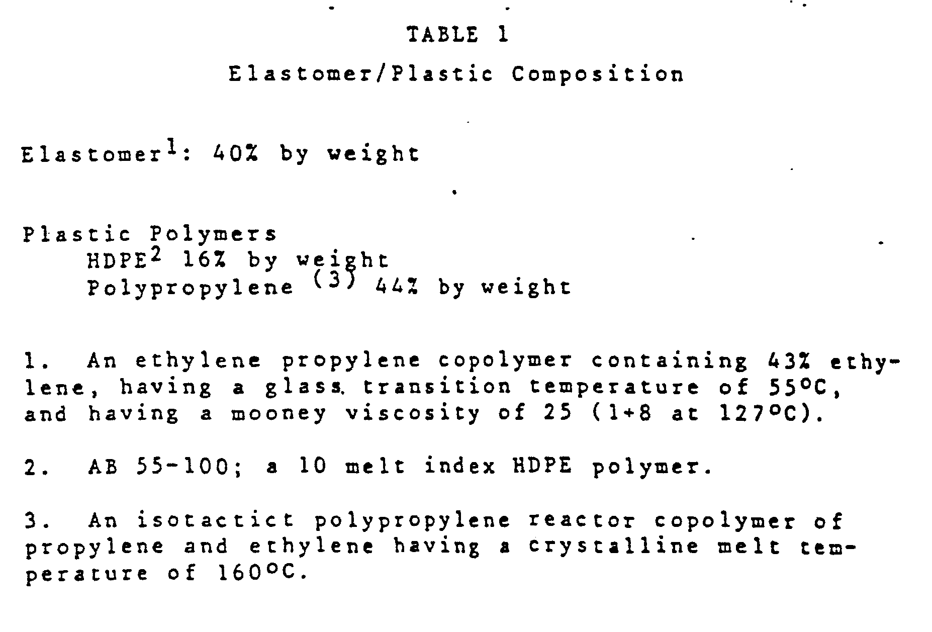
- an elastomer-plastic polymer composition having the formulation shown in Table I was extruded through a conventional multi-orificed strand die and cooled by passing the polymer strands through a water bath. Subsequently, the strands were pelletized. Additionally the same formulation was pelletized using an underwater pelletizer.
- the underwater cut pellets had a plastic skin, a lower coefficient of friction and were more free flowing than the conventional strand pelletized material.
- Table II compares the coefficient of friction of the two products, and Table III shows the pressure/strength ratio for the compositions.
- the pressure/strength .ratio is the ratio of the consolidation pressure to yield strength under the shear required to create pellet flow. A higher ratio is indicative of a more free flowing pellet.
- the MUP was operated with an extruder melt temperature of 408 0 F, an extruder pressure of 1600 psi and cooling water temperature of 105°F.
- the extruder output rate was 125 lbs/hr.
- Figure 1A and B are SEM micrograph comparisons of the strand formed pellets (Fig.lA) and the underwater cut pellets (Fig.lB).
- the rubber phase of the composition was extracted with hexane.
- the product produced according to the process of this invention has a skin which is substantially all plastic polymer while the pelletized strands are essentially of uniform composition throughout.
- a first polymer must be insoluble in a second polymer in the melt state, and that the polymers have. softening or melt points which are separated from one another by at least 10°C; preferably at least about 30°C; more preferably at least about.40 0 C.
- the polymer which is intended to produce the "skin".of the composite, must have the higher melting point.
- the core of the pellet is generally an elastomer.
- the second polymer of the film composition need not be an elastomer so long as the foregoing criter'ia are met.
- the film may be produced using conventional film forming techniques, e.g., blown, cast or tubular. water bath methods.
- film forming techniques e.g., blown, cast or tubular. water bath methods.
- a die surface in order to form the "skin" on at least one surface of the composite, a die surface must be cooled in the aforedescribed manner.
- a conventional method of preparing blown film utilizing an "A" frame and nip roll provides for cooling of the extruded, blown_film using an annular water bath which surrounds the film bubble and cools it.
- This technique can be modified by cooling the inner die outlet l ip either by water cooling the face or by using a water cooled mandrel in extruding the blown film and cooling the mandrel.
- a slit die may be used to prepare coated film. If only the upper or lower die outlet lip is cooled a film comprising two layers, the plastic layer and an elastomer or second plastic layer is formed. Where both die lips are cooled, a sandwich is prepared'with outer skins of plastic polymer and an inner core of elastomer or second plastic polymer.
- a second plastic polymer may be compounded with chemical blowing agents.
- a pneumatogen e.g., Freon
- Freon may be injected into the extruder melt.
- the resulting product has a foamed core between two plastic polymer skins.
- an elastomer is blended with tackifier resins, e.g., terpene resins to form a pressure sensitive or melt adhesive. Only one die outlet lip is cooled. 'The resulting product is an adhesive coated film of plastic polymer useful as wall or shelf coverings.
- tackifier resins e.g., terpene resins
- a sandwich can be prepared having a heat sealable plastic skin and a flexible elastomer core.
- the product is useful for flexible packaging operations, e.g., medical solution bags.
- thermoplastic polyesters e.g., thermoplastic polyesters, ionically crosslinked polymers, PVC, etc.
- ionically crosslinked polymers included sulfonated EPDM and carboxylic acid polymers of ethylene or carboxylic acid copolymers of styrene.
Abstract
Composite film comprising at least one layer of a first plastic polymer and a substrate of a second polymer/first plastic polymer composition is prepared by intimately mixing 15 to 90 wt.% of first plastic polymer and 10 to 85 wt.% of the second polymer, extruding the mixture through a film die while cooling at least one surface of the die outlet at least 10 degrees C below the melting point of the plastic polymer and cooling the film.
Description
- Many elastomers are tacky or exhibit cold flow in their green or uncured state. As a consequence, these materials cannot be transported in bulk as free flowing pellets but must be shipped in bales. This practice requires that the ultimate elastomer processor must be equipped to cut up or mill the bales. The necessary equipment is generally large scale, expensive equipment. Additionally, the bales cannot be readily preblended with other materials. The necessity for baling results in high handling and shipping costs. In order to facilitate handling and processing of elastomers, it has been considered desirable to produce elastomer pellets. Generally, however, elastomer pellets exhibit "blocking" or cold flow characteristics which result in solidification into a solid mass after a short storage time, especially at warm temperatures.
- Numerous attempts have been made to formulate elastomeric pellets which will remain free flowing until they are to be processed. Dusting the elastomeric pellets with inorganic materials, e.g., clay, talc, etc., has been found to extend the time over which the pellets are free flowing. Improved results have been achieved by dusting a coating with selected organic materials such as hydrocarbon waxes (British Patent 901,664) or powdered polyethylenes and polypropylenes (British Patent 928,120). However, because of the discontinuity of the dust coat, the coated pellets eventually flow together to form a solid mass.
- By blending the elastomer with a crystalline type polymer such as polyethylene, polypropylene or copolymers of ethylene and propylene, it has been possible to produce free flowing elastomer containing pellets. However, the elastomer content of the pellet must be less than about 65%. The product is, of course, not suitable for use in all elastomer applications.
- Another coating approach to the problem has been the coating of elastomer pellets with emulsions containing a tack free coating material. Coating is accomplished either by dipping pellets into the emulsion or spraying the emulsion onto the pellets. In either case the emulsion coating must be dried, and where the emulsion contains a solvent the solvent must be recovered. Drying and solvent recovery requirements result in increased costs.
- Melt-coating methods for producing free-flowing elastomer pellets have also been suggested. According to U.S. 3,669,772 to Bishop, coating can be accomplished by using a die., similar to wire coating die, into which a strand of rubber to be coated is fed simultaneous with melt coating material. A continuous melt coated strand of rubber issues from the coextrusion die outlet, is cooled in a liquid cooling bath, and is subsequently pelletized. This melt-coating method not only adds significantly to rubber manufacturing costs, but has limitations from the standpoint of efficiently producing large quantities of coated pellets.
- Pellets of rubber have been coated with various coating materials by heating the rubber pellet to a temperature which is higher than the melting point of the coating material, and then contacting the heated pellet with the coating material which is preferably in the form of a fine powder. The heated pellet fluxes the coating material on the surface of the pellet to form a substantially continuous coating. The hot coated pellet is then cooled.
- A study of bicomponent mixtures has shown that upon extrusion of the mixtures, stratification will occur. See Soulborn, J.H. and Ballman, R.L.; "Stratified Bicomponent Flow of Polymer Melts in a Tube", Applied Polymer Science, No.20, 175-189 (1973). The authors attribute stratification to differences in the melt viscosity of the components.
- It has surprisingly been found that a composite film comprising at least one layer of a first plastic polymer and a substrate of a second polymer/first plastic polymer composition can be prepared by intimately mixing about 15 to about 90 wt.2 of first plastic polymer and about 10 to about 85 wt.X of the second polymer, extruding the mixture through a film die while cooling at least one surface of the die outlet at least about 10°C below the melting point of the plastic polymer and cooling the film. In a preferred embodiment the first plastic polymer has a semicrystalline or crystalline melting point which is at least 100C above the softening or melting point of the second polymer.
- A sandwich type laminate comprising two outer skins of first plastic polymer enclosing a core comprising a blend of first plastic polymer and second polymer can be prepared by cooling both die outlet surfaces. Where a blown film die is utilized the inner and outer die layers must be cooled to accomplish this end. In a sheet die both the upper and lower die layers are cooled.
- Lhe accompanying drawings shnw:
- Figure lA - Scanning Electron Microscope (SEM) micrograph of strand-cut pellet sections microtomed at liquid nitrogen temperatures.
- Figure 1B - SEM micrograph of under-water pelletized pellet sections microtomed at liquid nitrogen temperature.
- Figure 2A - SEM of surface of strand-cut pellet section microtomed at liquid nitrogen temperatures showing rubber extracted from the surface.
- Figure 2B - SEM of surface of under-water pelletized pellet section microtomed at liquid nitrogen temperatures showing continuous thermoplastic skin with no rubber extracted.
- This invention relates to a method for preparing composite films. More particularly, it relates to a method for preparing composite films of a first plastic polymer and a subscrate of a second polymer/ first plastic polymer substrate in a single step extrusion process. The process of this invention may advantageously be utilized to produce sandwich type composite film laminates comprising a core which comprises a blend of the first plastic polymer and second polymer having outer skins comprising the first plastic polymer.
- By way of illustration the process of this invention is, described in terms of preparing a pellet comprising a blend of first plastic polymer and second polymer coated with a skin of first plastic polymer. By reference to this disclosure, however, its applicability to the preparation of composition films will be readily apparent to those skilled in the art.
- In the practice of this invention an elastomer is blended with a semi crystalline or crystalline plastic material which has a melting point of at. least 10°C higher than the softening point of the elastomer, preferably at least about 15°C than the softening point of the elastomer, preferably at least 30°C, more preferably at least 40°C. The elastomer/plastic blend is then extruded through a die in which the die outlet is maintained at least 10°C below the melting point of the plastic in order to develop a temperature gradient across the die from die inlet to die outlet, preferably at least 20°C, more preferably at least about 300C below the melting point of the plastic.
- Not wishing to be bound by theory, it is believed that as the melt temperature is reduced across the die, the difference in viscosity between the elastomer and the plastic is increased thereby causing stratification in a manner so as to cause the plastic to be concentrated along the surface of the die orifice while the central core becomes elastomer rich. Shear plays an important part in the stratification process as does the wall effect because of their effect on the velocity profile of the two components of the melt, and hence, the composition differences throughout the melt exiting the die. The melting point of the polymer is a function of shear and pressure, and is higher in the dynamic system of an extruder die than the static melting point of the polymer. As used in the specification and claims, "melting point" will mean the normal static melting point or softening point of the polymer.
- The elastomer/plastic polymer composition is extruded through a multi-orificed strand die in the aforedescribed manner and pelletized either by use of a strand pelletizer or by using a die face pelletizer. In one embodiment a conventional strand die is modified by having the die outlet plate cored so that it can be water cooled. In a preferred embodiment the die cooling is accomplished by using an underwater pelletizer. Typical of these underwater pelletizers is the mini underwater pelletizer (MUP) manufactured by Gala Industries, Inc., Eagle Rock, VA.
- Since the stratification process by which a pellet coated with a skin of plastic is formed requires a finite time the L/D ratio of the die outlet holes is an important criterion in carrying out the process of this invention. The L/D ratio can be about 2 to about 20, preferably about 2.5 to about 12, more preferably about 3 to about 10, e.g., about 3.5 to. about 8; The die outlets through which strands of elastomer/plastic:blends are extruded can be converging tubular outlets which have a larger diameter. inlet than outlet. In that event, the L/D ratio is based on an average outlet diameter over the length of the channel.
- The length of the outlet channel can be about 1 .inch to about.4 inches, preferably about 1.5 to about 3.5 inches, more preferably about 2.0 to about 3.0 inches, e.g., about 2.5 inches. The diameter of the die outlet orifice can be about 0.05 to about 0.200 inches, preferably about 0.075 to about 0.150 inches, e.g., about 0.125 inches.
- A critical parameter in carrying out the process of this invention is the temperature gradient across the die from the inlet to the outlet. While no particular temperature gradient is required, at some point within. the die the melt temperature must be reduced to a temperature which is preferably at about the melting point of the plastic in order to insure that there is a significant difference between the viscosity of the plastic melt and the viscosity of the elastomer melt. It is not essential that the melt temperature of the composition be below that of the plastic melt point. In a preferred embodiment, however, the melt temperature of the composition is reduced to a temperature which is below the melting point of the plastic component. In the preferred method of carrying out the process of this invention, an underwater pelletizer is used and the temperature gradient across the die is created by cooling the face of the die.
- The maximum temperature differential across the die is achieved by operating at or about the plugging temperature of the system. The "plugging temperature" is that temperature at which some of the die outlet orifices begin to be plugged by solidified polymer. Some plugging of a multi-orifice die can be tolerated up to the point where flow rate is decreased below economical rates. Generally, the outer outlet holes in the die will plug first. A multi-orifice die will have twenty or more outlet holes, e.g., 50-100. It is possible to operate the die at the plugging temperature with as much as about 20-30% of the holes plugged.
- The plugging temperature is determined by gradually cooling the die or die face to the point where outlet hole plugging begins to occur. Operation at the plugging temperature achieves the maximum stratification and plastic skin development in the elastomer pellet.
- Where an underwater pelletizer is used, the cooling water temperature will be about 20°C to about 50°C. The "extruder melt temperature" (the die inlet melt temperature) will be about 160°C to about 250°C and will depend on the elastomer and plastic selected. The appropriate extruder melt temperature for various plastic/elastomer compositions is known to those skilled in-the extrusion art.
- The process of this invention is particularly suited to those elastomers which are tacky in their solid state or exhibit cold flow. Illustrative, non-limiting examples of the elastomers to which this invention may be applied are high molecular weight elastomers having a Tg of less than 0°C, e.g. ethylene-propylene rubber (EPR), terpolymers of ethylene, propylene and a non-conjugated diene (EPDM), natural rubber, polyisobutylene, butyl rubber, halogenated butyl rubber, acrylonitrile-butadiene rubber (NBR) and styrene butadiene rubber (SBR).
- The plastics which may be utilized in the practice of this invention have a crystalline melting point of at least 70°C. Illustrative of those plastic polymers are high density polyethylene (HDPE), low density polyethylene (LDPE), polypropylene (PP), LLDPE, syndiotactic polybutadiene resin (SBD), polybutene-1 and crystalline copolymers of ethylene and other alphaolefins. The plastic and elastomer must be insoluble in one another in the melt state.
- The elastomer-plastic polymer composition of this invention can comprise about 15 to about 90 weight percent plastic polymer, e.g. about 20 to about 80 weight percent. where the product desired is an elastomeric product the plastic polymer comprises about 15 to about 35 weight percent of the composition; preferably about 15 to about 30 weight percent, most preferably about 20 to about 28 weight percent, e.g., about 25 wt.%.
- The plastic and polymer may be blended in any conventional manner and fed to an extruder. For example, an elastomer bale can be. shredded and blended with plastic polymer powder in a ribbon blender and subsequently fed to an extruder. Preferably a mixing extruder, e.g., twin screw extruder is used for the extrusion to insure complete mixing of the elastomer and plastic. The mixture is extruded out of a conventional multi-orificed die in which the die face is maintained at a temperature of at least about 10°C below the melting point of the plastic polymer. Preferably the die face is maintained at a temperature at least about 10°C below the melting point of the plastic polymer; more preferably at least about 20°C; most preferably at least about 30°C below the melting point of the plastic. Of course, in view of the high melt temperature of the polymers the entire die plate cannot be maintained at a single temperature, and there will be a temperature gradient across the die from its internal inlet surface to its outer face at the outlet of the die.
- To demonstrate the effectiveness of the instant invention, an elastomer-plastic polymer composition having the formulation shown in Table I was extruded through a conventional multi-orificed strand die and cooled by passing the polymer strands through a water bath. Subsequently, the strands were pelletized. Additionally the same formulation was pelletized using an underwater pelletizer.
- The underwater cut pellets had a plastic skin, a lower coefficient of friction and were more free flowing than the conventional strand pelletized material. Table II compares the coefficient of friction of the two products, and Table III shows the pressure/strength ratio for the compositions. The pressure/strength .ratio is the ratio of the consolidation pressure to yield strength under the shear required to create pellet flow. A higher ratio is indicative of a more free flowing pellet.


- In preparing the underwater die cut pellets of this invention, the MUP was operated with an extruder melt temperature of 4080F, an extruder pressure of 1600 psi and cooling water temperature of 105°F. The extruder output rate was 125 lbs/hr.
- It is evident from the above data that pellets made according to the process of this invention are more free flowing than strand pelletized material even where the compositions are identical. Figure 1A and B are SEM micrograph comparisons of the strand formed pellets (Fig.lA) and the underwater cut pellets (Fig.lB). The rubber phase of the composition was extracted with hexane. As can be seen from the micrograph of FiglB, the product produced according to the process of this invention has a skin which is substantially all plastic polymer while the pelletized strands are essentially of uniform composition throughout.
- In order to demonstrate that the skin of the pellets of this invention are substantially all plastic polymer, the pellets were treated with hexane to extract the rubber phase. A comparison of Figures 2A and 2B show that rubber was extracted from the surface of the conventional strand pelletized material, whereas substantially no rubber was extracted from the skin of the pellets prepared according to the process of this invention.
- While the invention has been described in terms of a process for manufacturing an elastomer coated pellet having a plastic polymer skin; it will be evident from the foregoing disclosure that the process can be utilized to prepare polymer film comprising a laminate of one polymeric material over another. Alternatively, it may be utilized to prepare a sandwich of one polymer material on each face of a second polymer material.
- The criteria for the manufacture of such films is that a first polymer must be insoluble in a second polymer in the melt state, and that the polymers have. softening or melt points which are separated from one another by at least 10°C; preferably at least about 30°C; more preferably at least about.400C. The polymer which is intended to produce the "skin".of the composite, must have the higher melting point.
- With respect to the description of the invention relating to free flowing pellets, the core of the pellet is generally an elastomer. The second polymer of the film composition need not be an elastomer so long as the foregoing criter'ia are met.
- The film may be produced using conventional film forming techniques, e.g., blown, cast or tubular. water bath methods. However, in order to form the "skin" on at least one surface of the composite, a die surface must be cooled in the aforedescribed manner.
- A conventional method of preparing blown film utilizing an "A" frame and nip roll provides for cooling of the extruded, blown_film using an annular water bath which surrounds the film bubble and cools it. This technique can be modified by cooling the inner die outlet lip either by water cooling the face or by using a water cooled mandrel in extruding the blown film and cooling the mandrel.
- Similarly a slit die may be used to prepare coated film. If only the upper or lower die outlet lip is cooled a film comprising two layers, the plastic layer and an elastomer or second plastic layer is formed. Where both die lips are cooled, a sandwich is prepared'with outer skins of plastic polymer and an inner core of elastomer or second plastic polymer.
- In another.embodiment of the invention, a second plastic polymer may be compounded with chemical blowing agents. Alternatively, a pneumatogen e.g., Freon, may be injected into the extruder melt. The resulting product has a foamed core between two plastic polymer skins.
- In another embodiment an elastomer is blended with tackifier resins, e.g., terpene resins to form a pressure sensitive or melt adhesive. Only one die outlet lip is cooled. 'The resulting product is an adhesive coated film of plastic polymer useful as wall or shelf coverings.
- Where the elastomer/plastic polymer composition has the formulation shown in Table I a sandwich can be prepared having a heat sealable plastic skin and a flexible elastomer core. The product is useful for flexible packaging operations, e.g., medical solution bags.
- In addition to the plastics described above, other polymers, e.g.; thermoplastic polyesters, ionically crosslinked polymers, PVC, etc. can be utilized to prepare the coated films of this invention. The ionically crosslinked polymers included sulfonated EPDM and carboxylic acid polymers of ethylene or carboxylic acid copolymers of styrene.
Claims (14)
1. A process for preparing a composite film comprising at least one layer of a first plastic polymer and a substrate of a second polymer/first plastic polymer composition wherein the plastic polymer has a semicrystalline or crystalline melting point which is at least 10 degrees C higher than the second polymer softening or melting point, the first plastic polymer comprising from 15 to 90 weight percent of the second polymer/first plastic polymer composition, the second polymer and plastic polymer being insoluble in one another, which comprises:
(a) intimately mixing the second polymer and first plastic polymer;
(b) extruding the mixture through a film die having a die outlet comprising a first die surface and a second die surface, whilst
(c) cooling at least one surface of the die outlet to a temperature at least 10 degrees C below the melting point of the plastic polymer; and
(d) cooling the film so formed.
2. The process according to Claim 1 wherein the first plastic polymer comprises from 15 to 60 weight percent of the second polymer/first plastic polymer mixture.
3. The process according to Claim 2 wherein the first plastic polymer comprises from 15 to 35 weight percent of the second polymer/first plastic polymer mixture.
4. The process according to claim 1, 2 or 3 wherein the second polymer is an elastomeric polymer having a Tg of less than Oo C.
5. The process according to Claim 4 wherein the elastomer comprises EPR, EPDM, NR, SBR, PIB, or halobutyl rubber, or mixtures thereof.
6. The process according to any one of the preceding claims wherein the first plastic polymer comprises HDPE, LPDE, LLDPE, polypropylene, polybutene-1, a crystalline copolymer of ethylene and an alphaolefin or mixtures thereof.
7. The process according to Claim 5 and 6 wherein the elastomer comprises EPR or EPDM and the plastic polymer comprises a crystalline ethylene-propylene copolymer, HDPE or mixtures thereof.
8. The process according to Claim 7 wherein the elastomer is an ethylene propylene copolymer and the plastic polymer is a blend of an HDPE and a crystalline copolymer of ethylene and propylene.
9. The process according to Claim 8 wherein the elastomer/plastic mixture comprises about 40 weight percent elastomer based on the elastomer/plastic mixture, the HDPE comprises about 16 weight percent of the elastomer/plastic mixture and the crystalline ethylene propylene copolymer comprises about 44 weight percent of the elastomer/plastic mixture.
10. The process according to Claim 4 or 5 wherein the plastic polymer is sulfonated EPDM ionomer or poly(ethylene glycol terephthalate).
11. The process according to any one of the preceding claims wherein the second polymer comprises an elastomer and is combined with a tackifier resin thereby forming an elastomeric pressure sensitive adhesive composition.
12. The process according to any one of the preceding claims wherein the die is a blown film die having an annular outlet bounded by an inner and outer die lip, only said inner die lip being cooled.
13. The process according to any one of claims 1 to 11 wherein both the first and second die surface are cooled.
14. A composite film produced by the process according to any one of claims 1 to 13 when in the form of wall or shelf covering, or a flexible packaging such as a medical solution bag.
Applications Claiming Priority (2)
| Application Number | Priority Date | Filing Date | Title |
|---|---|---|---|
| US06/809,511 US4803035A (en) | 1985-12-16 | 1985-12-16 | Method for making composite films |
| US809511 | 1985-12-16 |
Publications (1)
| Publication Number | Publication Date |
|---|---|
| EP0227421A1 true EP0227421A1 (en) | 1987-07-01 |
Family
ID=25201506
Family Applications (1)
| Application Number | Title | Priority Date | Filing Date |
|---|---|---|---|
| EP86309833A Ceased EP0227421A1 (en) | 1985-12-16 | 1986-12-16 | Method for making composite films |
Country Status (3)
| Country | Link |
|---|---|
| US (1) | US4803035A (en) |
| EP (1) | EP0227421A1 (en) |
| WO (1) | WO1987003533A1 (en) |
Cited By (3)
| Publication number | Priority date | Publication date | Assignee | Title |
|---|---|---|---|---|
| EP0530977A2 (en) * | 1991-09-06 | 1993-03-10 | Tri- Seal International Inc. | Cap liner for hot filled container, and method for its manufacture |
| WO1994007954A1 (en) * | 1992-10-02 | 1994-04-14 | E.I. Du Pont De Nemours And Company | Improved shrink film and methods relating thereto |
| US6514583B1 (en) | 1992-11-13 | 2003-02-04 | Cryovac, Inc. | High impact strength film containing single site catalyzed copolymer |
Families Citing this family (15)
| Publication number | Priority date | Publication date | Assignee | Title |
|---|---|---|---|---|
| US4933124A (en) * | 1986-08-18 | 1990-06-12 | Mobil Oil Corporation | Process of applying a silicone release coating to an oriented polymer film |
| JPH0717756B2 (en) * | 1988-06-30 | 1995-03-01 | 日本石油株式会社 | Method for producing masterbatch composition for modifying thermoplastic resin |
| DE69002295T2 (en) | 1989-09-25 | 1993-11-04 | Schneider Usa Inc | MULTILAYER EXTRUSION AS A METHOD FOR PRODUCING BALLOONS FOR VESSEL PLASTICS. |
| US5195969A (en) | 1991-04-26 | 1993-03-23 | Boston Scientific Corporation | Co-extruded medical balloons and catheter using such balloons |
| JP3624315B2 (en) * | 1992-07-29 | 2005-03-02 | バクスター、インターナショナル、インコーポレイテッド | Biological material with hydrophilic surface |
| US6896842B1 (en) * | 1993-10-01 | 2005-05-24 | Boston Scientific Corporation | Medical device balloons containing thermoplastic elastomers |
| WO1995009667A1 (en) | 1993-10-01 | 1995-04-13 | Boston Scientific Corporation | Medical device balloons containing thermoplastic elastomers |
| US5700412A (en) * | 1993-11-01 | 1997-12-23 | E. I. Du Pont De Nemours And Company | Process for making laminar articles |
| US6143818A (en) * | 1999-08-04 | 2000-11-07 | Ato Findley, Inc. | Hot melt adhesive based on ethylene-propylene rubber (EPR) and semicrystalline olefinic polymers |
| US6329468B1 (en) | 2000-01-21 | 2001-12-11 | Bostik Findley, Inc. | Hot melt adhesive based on semicrystalline flexible polyolefins |
| US6846532B1 (en) | 2001-02-15 | 2005-01-25 | Sonoco Development, Inc. | Laminate packaging material |
| WO2003040231A1 (en) * | 2001-11-05 | 2003-05-15 | Bridgestone Corporation | Process for producing blends of syndiotactic 1,2-polybutadiene and rubbery elastomers |
| US20060147685A1 (en) * | 2004-12-30 | 2006-07-06 | Kimberly-Clark Worldwide, Inc. | Multilayer film structure with higher processability |
| CN101460123A (en) * | 2006-06-07 | 2009-06-17 | 宝洁公司 | Biaxially stretchable outer cover for an absorbent article |
| KR101582119B1 (en) * | 2011-05-17 | 2016-01-04 | 도레이 플라스틱스 아메리카 인코오포레이티드 | Crosslinked polypropylene foam and laminates made therefrom |
Citations (4)
| Publication number | Priority date | Publication date | Assignee | Title |
|---|---|---|---|---|
| DE1504331A1 (en) * | 1964-08-14 | 1969-10-02 | Grace W R & Co | Process for the treatment of incompatible polymers |
| DE1704561A1 (en) * | 1967-02-17 | 1972-03-30 | Cellophane Sa | Process for producing an oriented opalescent plastic film with a pearlescent effect |
| DE1923852B2 (en) * | 1969-05-09 | 1972-12-28 | Alkor-Werk, Karl Lissmann KG, 8000 München | METHOD AND DEVICE FOR MANUFACTURING A PARTIALLY STRETCHED PLASTIC FILM MATERIAL |
| EP0090554A2 (en) * | 1982-03-18 | 1983-10-05 | E.I. Du Pont De Nemours And Company | Low temperature lamellar article stretching |
Family Cites Families (30)
| Publication number | Priority date | Publication date | Assignee | Title |
|---|---|---|---|---|
| US2795821A (en) * | 1954-03-16 | 1957-06-18 | Okonite Co | Production of extruded shapes having textured surfaces without recourse to external mechanical devices, such as embossing rolls and the like |
| DE1966466C3 (en) * | 1969-05-09 | 1974-10-10 | Alkor-Werk, Karl Lissmann Kg, 8000 Muenchen | Method and device for producing a composite film web. Eliminated from: 1923852 |
| US4053548A (en) * | 1971-11-17 | 1977-10-11 | Exxon Research & Engineering Co. | Fabrication process for multiphased plastics |
| US3949039A (en) * | 1972-04-03 | 1976-04-06 | Japan Steel Works, Ltd. | Method for pelletizing synthetic resins having a high melting point |
| DE2535286C3 (en) * | 1975-08-07 | 1979-01-25 | Dynamit Nobel Ag, 5210 Troisdorf | Method for calibrating a coextruded profile strip made of thermoplastics |
| US4196754A (en) * | 1976-05-10 | 1980-04-08 | The Gates Rubber Company | Molded rubber article |
| NL184903C (en) * | 1976-06-11 | 1989-12-01 | Monsanto Co | PROCESS FOR PREPARING AN ELASTOPLASTIC MATERIAL, CONTAINING A THERMOPLASTIC, LINEAR, CRYSTALLINE POLYESTER AND A CROSSED RUBBER. |
| JPS5334859A (en) * | 1976-09-10 | 1978-03-31 | Mitsubishi Heavy Ind Ltd | Extruder for molding multilayer composite film |
| FR2369070A1 (en) * | 1976-10-29 | 1978-05-26 | Ato Chimie | F PROCESS |
| US4183887A (en) * | 1977-04-28 | 1980-01-15 | Copolymer Rubber & Chemical Corporation | Method for producing free flowing particles of elastomeric material |
| JPS5493043A (en) * | 1977-12-29 | 1979-07-23 | Unitika Ltd | Resin composition and its production |
| US4221882A (en) * | 1979-01-31 | 1980-09-09 | Exxon Research & Engineering Co. | High impact melt-flowable dual continuum melt mixed polymer blends of polypropylene, polyethylene, and ethylene-propylene rubber |
| US4410482A (en) * | 1979-03-06 | 1983-10-18 | E. I. Du Pont De Nemours & Co. | Process for making laminar articles of polyolefin and a condensation polymer |
| JPS5667209A (en) * | 1979-11-05 | 1981-06-06 | Du Pont Mitsui Polychem Co Ltd | Tack-free resin pellet and method of manufacturing thereof |
| US4323534A (en) * | 1979-12-17 | 1982-04-06 | The Procter & Gamble Company | Extrusion process for thermoplastic resin composition for fabric fibers with exceptional strength and good elasticity |
| US4289727A (en) * | 1979-12-19 | 1981-09-15 | Mobil Oil Corporation | Method for extrusion of tubular films |
| US4247661A (en) * | 1979-12-26 | 1981-01-27 | The B. F. Goodrich Company | Thermoplastic polymer blends comprising EP or EPDM polymers and highly crystalline polyallomers |
| JPS57165436A (en) * | 1981-04-07 | 1982-10-12 | Toa Nenryo Kogyo Kk | Polyethylene composition |
| US4367113A (en) * | 1981-06-29 | 1983-01-04 | Gulf Oil Corporation | Multicomponent polymer compositions |
| US4370432A (en) * | 1981-09-04 | 1983-01-25 | Exxon Research And Engineering Co. | Hot melt adhesive compositions of neutralized sulfonated EPDM and tackifier mixture |
| US4664866A (en) * | 1981-11-25 | 1987-05-12 | The Dow Chemical Company | Method for preparing a film having preferential one-sided cling |
| JPS5896666A (en) * | 1981-12-05 | 1983-06-08 | Okura Ind Co Ltd | Two-pack type adhesive |
| JPS58208021A (en) * | 1982-05-31 | 1983-12-03 | Kyoraku Co Ltd | Blow molding and manufacture thereof |
| US4558096A (en) * | 1983-03-14 | 1985-12-10 | The Goodyear Tire & Rubber Company | High performance rubber-polyester blends |
| JPS59167253A (en) * | 1983-03-15 | 1984-09-20 | 三菱化学株式会社 | Three layer coextrusion inflation film |
| US4532100A (en) * | 1983-05-06 | 1985-07-30 | The Dow Chemical Company | Blown nylon film and process for the preparation thereof |
| JPS606431A (en) * | 1983-06-27 | 1985-01-14 | Idemitsu Petrochem Co Ltd | Manufacture of cylindrical laminated film |
| US4543385A (en) * | 1983-12-28 | 1985-09-24 | Exxon Research And Engineering Co. | Blend compositions of sulfo EPDM's having improved compression set properties |
| JPS60238332A (en) * | 1984-05-11 | 1985-11-27 | Toppan Printing Co Ltd | Molded plastic article having picture pattern |
| US4622193A (en) * | 1984-06-15 | 1986-11-11 | Exxon Research & Engineering Co. | Method for making free flowing coated rubber pellets |
-
1985
- 1985-12-16 US US06/809,511 patent/US4803035A/en not_active Expired - Fee Related
-
1986
- 1986-12-15 WO PCT/US1986/002697 patent/WO1987003533A1/en unknown
- 1986-12-16 EP EP86309833A patent/EP0227421A1/en not_active Ceased
Patent Citations (4)
| Publication number | Priority date | Publication date | Assignee | Title |
|---|---|---|---|---|
| DE1504331A1 (en) * | 1964-08-14 | 1969-10-02 | Grace W R & Co | Process for the treatment of incompatible polymers |
| DE1704561A1 (en) * | 1967-02-17 | 1972-03-30 | Cellophane Sa | Process for producing an oriented opalescent plastic film with a pearlescent effect |
| DE1923852B2 (en) * | 1969-05-09 | 1972-12-28 | Alkor-Werk, Karl Lissmann KG, 8000 München | METHOD AND DEVICE FOR MANUFACTURING A PARTIALLY STRETCHED PLASTIC FILM MATERIAL |
| EP0090554A2 (en) * | 1982-03-18 | 1983-10-05 | E.I. Du Pont De Nemours And Company | Low temperature lamellar article stretching |
Cited By (7)
| Publication number | Priority date | Publication date | Assignee | Title |
|---|---|---|---|---|
| EP0530977A2 (en) * | 1991-09-06 | 1993-03-10 | Tri- Seal International Inc. | Cap liner for hot filled container, and method for its manufacture |
| EP0530977A3 (en) * | 1991-09-06 | 1993-08-11 | Tri- Seal International Inc. | Cap liner for hot filled container, and method for its manufacture |
| US5601200A (en) * | 1991-09-06 | 1997-02-11 | Tri-Seal International, Inc. | Cap liner for hot filled container and method |
| WO1994007954A1 (en) * | 1992-10-02 | 1994-04-14 | E.I. Du Pont De Nemours And Company | Improved shrink film and methods relating thereto |
| US6514583B1 (en) | 1992-11-13 | 2003-02-04 | Cryovac, Inc. | High impact strength film containing single site catalyzed copolymer |
| US8017231B1 (en) | 1992-11-13 | 2011-09-13 | Cryovac, Inc. | Heat shrinkable films containing single site catalyzed copolymers having long chain branching |
| US8021759B1 (en) | 1992-11-13 | 2011-09-20 | Cryovac Inc. | Heat shrinkable films containing single site catalyzed copolymers |
Also Published As
| Publication number | Publication date |
|---|---|
| WO1987003533A1 (en) | 1987-06-18 |
| US4803035A (en) | 1989-02-07 |
Similar Documents
| Publication | Publication Date | Title |
|---|---|---|
| US4803035A (en) | Method for making composite films | |
| US4622193A (en) | Method for making free flowing coated rubber pellets | |
| EP0095898B1 (en) | Method for making free-flowing melt-coated rubber pellets | |
| EP0169654A2 (en) | Coated pellets and film compositions | |
| US4713271A (en) | Foamed polymer tubing | |
| US4303710A (en) | Coextruded multi-layer polyethylene film and bag construction | |
| KR960003278B1 (en) | Polypropylene foam sheets | |
| US4668571A (en) | Coextrustion tie layer and process for producing such tie layer | |
| US4390573A (en) | Laminar thermoplastic film constructions | |
| JPS5828379A (en) | Polyethylene bag film | |
| US4357191A (en) | Laminar thermoplastic film constructions | |
| AU778030B2 (en) | Multilayer heat-shrinkable sealable films | |
| WO1997022656B1 (en) | Thermoplastic foam and process for producing it using carbon dioxide | |
| HU199271B (en) | Shoe-industrial stiffener | |
| KR100367820B1 (en) | Film/substrate composite material | |
| JP2021509372A (en) | Shrinkable film that can be layered and heat-sealed, its manufacturing method, and packaging bags manufactured using it. | |
| US4822545A (en) | Method for making free-flowing coated rubber pellets | |
| CA1323123C (en) | Concentrate of polyolefins and modifying agent | |
| US4970118A (en) | Method for making free-flowing coated rubber pellets | |
| CA1188447A (en) | Film forming composition of pelletized ldpe | |
| GB2388814A (en) | Cold sealing polymeric films | |
| CA2171150A1 (en) | Method for protecting waterproofed substrate surfaces and structures for accomplishing same | |
| US4022858A (en) | Method for the production of foamed thermoplastic film having improved resiliency and flexibility characteristics | |
| JP2001115791A (en) | Waterproof sheet for tunnel | |
| EP0228818B1 (en) | Polyethylene blends, films and articles of packaging made therefrom |
Legal Events
| Date | Code | Title | Description |
|---|---|---|---|
| PUAI | Public reference made under article 153(3) epc to a published international application that has entered the european phase |
Free format text: ORIGINAL CODE: 0009012 |
|
| 17P | Request for examination filed |
Effective date: 19870109 |
|
| AK | Designated contracting states |
Kind code of ref document: A1 Designated state(s): AT BE CH DE ES FR GB IT LI LU NL SE |
|
| 17Q | First examination report despatched |
Effective date: 19890505 |
|
| STAA | Information on the status of an ep patent application or granted ep patent |
Free format text: STATUS: THE APPLICATION HAS BEEN REFUSED |
|
| 18R | Application refused |
Effective date: 19920202 |
|
| RIN1 | Information on inventor provided before grant (corrected) |
Inventor name: HAZELTON, DONALD ROSS Inventor name: KRESGE, EDWARD NATHAN |