EP0228828A2 - Continuous ink jet printing system - Google Patents
Continuous ink jet printing system Download PDFInfo
- Publication number
- EP0228828A2 EP0228828A2 EP86309465A EP86309465A EP0228828A2 EP 0228828 A2 EP0228828 A2 EP 0228828A2 EP 86309465 A EP86309465 A EP 86309465A EP 86309465 A EP86309465 A EP 86309465A EP 0228828 A2 EP0228828 A2 EP 0228828A2
- Authority
- EP
- European Patent Office
- Prior art keywords
- ink
- tank
- level
- viscosity
- signal
- Prior art date
- Legal status (The legal status is an assumption and is not a legal conclusion. Google has not performed a legal analysis and makes no representation as to the accuracy of the status listed.)
- Granted
Links
Images


Classifications
-
- G—PHYSICS
- G01—MEASURING; TESTING
- G01N—INVESTIGATING OR ANALYSING MATERIALS BY DETERMINING THEIR CHEMICAL OR PHYSICAL PROPERTIES
- G01N11/00—Investigating flow properties of materials, e.g. viscosity, plasticity; Analysing materials by determining flow properties
- G01N11/02—Investigating flow properties of materials, e.g. viscosity, plasticity; Analysing materials by determining flow properties by measuring flow of the material
- G01N11/04—Investigating flow properties of materials, e.g. viscosity, plasticity; Analysing materials by determining flow properties by measuring flow of the material through a restricted passage, e.g. tube, aperture
- G01N11/06—Investigating flow properties of materials, e.g. viscosity, plasticity; Analysing materials by determining flow properties by measuring flow of the material through a restricted passage, e.g. tube, aperture by timing the outflow of a known quantity
-
- B—PERFORMING OPERATIONS; TRANSPORTING
- B41—PRINTING; LINING MACHINES; TYPEWRITERS; STAMPS
- B41J—TYPEWRITERS; SELECTIVE PRINTING MECHANISMS, i.e. MECHANISMS PRINTING OTHERWISE THAN FROM A FORME; CORRECTION OF TYPOGRAPHICAL ERRORS
- B41J2/00—Typewriters or selective printing mechanisms characterised by the printing or marking process for which they are designed
- B41J2/005—Typewriters or selective printing mechanisms characterised by the printing or marking process for which they are designed characterised by bringing liquid or particles selectively into contact with a printing material
- B41J2/01—Ink jet
- B41J2/17—Ink jet characterised by ink handling
- B41J2/18—Ink recirculation systems
-
- B—PERFORMING OPERATIONS; TRANSPORTING
- B41—PRINTING; LINING MACHINES; TYPEWRITERS; STAMPS
- B41J—TYPEWRITERS; SELECTIVE PRINTING MECHANISMS, i.e. MECHANISMS PRINTING OTHERWISE THAN FROM A FORME; CORRECTION OF TYPOGRAPHICAL ERRORS
- B41J2/00—Typewriters or selective printing mechanisms characterised by the printing or marking process for which they are designed
- B41J2/005—Typewriters or selective printing mechanisms characterised by the printing or marking process for which they are designed characterised by bringing liquid or particles selectively into contact with a printing material
- B41J2/01—Ink jet
- B41J2/17—Ink jet characterised by ink handling
- B41J2/195—Ink jet characterised by ink handling for monitoring ink quality
-
- Y—GENERAL TAGGING OF NEW TECHNOLOGICAL DEVELOPMENTS; GENERAL TAGGING OF CROSS-SECTIONAL TECHNOLOGIES SPANNING OVER SEVERAL SECTIONS OF THE IPC; TECHNICAL SUBJECTS COVERED BY FORMER USPC CROSS-REFERENCE ART COLLECTIONS [XRACs] AND DIGESTS
- Y10—TECHNICAL SUBJECTS COVERED BY FORMER USPC
- Y10T—TECHNICAL SUBJECTS COVERED BY FORMER US CLASSIFICATION
- Y10T137/00—Fluid handling
- Y10T137/8593—Systems
- Y10T137/85978—With pump
- Y10T137/86131—Plural
- Y10T137/86139—Serial
- Y10T137/86147—With single motive input
Definitions
- the present invention relates to a continuous ink jet printing system and in particular to a means of measuring the viscosity of ink in the system during use.
- ink is passed from a reservoir to a print head under pressure, the ink being forced through a nozzle and broken up into droplets which are charged according to the desired print position, the charged droplets then being deflected onto the target by an electrostatic field. Uncharged droplets are returned to the reservoir.
- volatile solvents are lost from the ink due to evaporation so that the composition and physical properties of the ink change with time. It is known therefore to measure the viscosity of the ink and to introduce solvents into the ink to maintain the desired viscosity.
- a falling ball viscometer In one known method, what is known as a "falling ball viscometer" is used, an upright tube being connected to a supply line for the ink and an element movable upwardly and downwardly within the tube being provided.
- a valve is positioned to control the flow of liquid from the supply line to the tube and a control means is arranged to open the valve to allow upwards flow of liquid in the tube sufficient to move the element to an upper part of the tube, subsequently closing the valve so as to terminate the upwards flow of liquid, and sensors being used to determine the time taken for the element to descend through a predetermined distance through the liquid within the tube.
- the time taken for the element to fall a known distance is representative of the viscosity of the liquid.
- the ink is charged with a component which causes a change in the viscosity to correct the difference between the measured viscosity and the desired viscosity.
- the clearance between the falling ball and the fluted wall of the tube is only a few microns and particles of ink and/or agglomerates of pigments or foreign bodies, if present, can seriously impede the free movement of the ball as it passes through the liquid thus causing incorrect measurement.
- a continuous ink jet printing system which comprises an ink circuit including an ink reservoir; a pump; a nozzle from which a continuous stream of ink droplets is projected in use under pressure from the pump; a device for collecting unused droplets; and a recirculation circuit for returning unused ink to the ink reservoir, further includes a means for determining the viscosity of the ink at selected intervals, the viscosity determining means having a measuring tank; an inlet to the tank connected to the ink circuit to receive ink under pressure, the inlet having a flow restriction; a vent/return pipe to vent the tank and enable ink to be returned to the reservoir; an outlet for draining ink from the tank and returning it to the pump, the outlet including a valve to open and close the outlet; a level detector in the tank; and a timer to determine the time taken for the tank to fill from a first level to a second level detected by the level detector and hence to provide a representation of the viscosity of the ink
- the temperature of the ink is monitored and the measured flow time is compared with the theoretical flow time at that temperature and if significantly different the viscosity of the ink is varied to bring it within range.
- a means for charging the ink with a component which causes a change in the viscosity to maintain the desired viscosity, the charging means being controlled in dependence upon the time determined by the timer.
- the invention also includes a continuous ink jet printing method using such a system, in which, at selected intervals, a valve in the outlet from the measuring tank is first opened to allow the tank to be emptied, and then closed to allow the tank to fill; a first signal is provided when the level of ink in the tank reaches a first level; a second signal is provided when the level of liquid in the tank reaches a second level; the time taken for the ink level to rise from the first level to the second level is measured and the outlet valve from the measuring tank is then opened to lower the level of ink in the tank to a level below the first level.
- a temperature sensing transducer may be provided in or near the inlet to the measuring tank to provide a signal indicative of the ink temperature, which signal may be sent to a microprocessor together with a signal indicative of the viscosity (a signal derived from the time taken for the tank to fill from the first to the second level), in order to provide a control signal to control the viscosity the ink.
- a pressure sensing transducer may be provided in or near the inlet to the measuring tank to provide a signal indicative of the ink pressure, which signal may be sent to a microprocessor together with a signal from the viscometer of the filling time and a signal indicative of the temperature of the ink, in order to allow the microprocessor to accurately calculate the viscosity of the ink, and compare this with the required viscosity which is stored in memory.
- a control signal is sent to control charging of the viscosity adjusting component into the ink.
- a particular advantage of this apparatus and method is that the pressure of ink supplied to the nozzle is regulated at about 40 psi (2.76 ⁇ 105 Pa) so that ink at this pressure can be fed to the viscometer.
- pressure variations as high as 5 psi (3.45 ⁇ 104 Pa) lead only to a maximum calculated viscosity variation of about 5.6 ⁇ 10 ⁇ 4 Pa.s - within the limits required for consistent print quality.
- The, if desired, measurement of actual pressure can be dispensed with as far as the viscosity measuring part of the system is concerned.
- the ink system shown in Figure 1 conveys ink from an ink reservoir 1 to a print head assembly which includes a nozzle head 16 and a gutter 22 by means of which drops which are not used for printing are returned to the ink system.
- the reservoir 1 is topped up from an ink cartridge 5 which can be replaced when empty and which provides top-up to the ink reservoir 1.
- a make-up cartridge 6 contains solvents which can be added to the ink to make up for loss of solvent due to evaporation from non-printed droplets returned through the gutter 22.
- the make-up cartridge feeds solvents through a filter 14 on demand via a line 7 through a solenoid valve 15 to the main return line from the gutter 22.
- the nozzle assembly 16 includes a piezo-electric transducer (not shown) which breaks a flow of ink into individual droplets which are then electrostatically charged by a variable amount in order to suit the desired print position on the target, unprinted drops being substantially uncharged.
- the stream of droplets passes between a pair of deflection electrodes, the electric field between which causes the charged droplets to be deflected by appropriate amounts and into their desired positions on target.
- the levels of charge on the individual droplets are controlled by a print microprocessor (not shown in Figure 1).
- the ink is passed by means of a double-ended pump 11 through a pressure relief valve 8 (to ensure that the ink pressure does not rise above 60 psi (4.14 ⁇ 105 Pa) in the line to the head assembly), ink for printing being led off between the double ended pump and the pressure relief valve 8 through a manually adjustable pressure regulator 17 (the pressure being monitored by an operator through a gauge 20 or sensed automatically by a pressure transducer 25), through a further filter 18, through a feed solenoid 19 and a further filter 24 to the nozzle assembly 16.
- a bleed line is provided from the nozzle head 16 to return a mixture of ink and entrained air from the head at start-up and shut-down, this being achieved through a bleed solenoid 21.
- ink On the return side ink is passed through a bleed control orifice 10 back to the double ended pump 11 and thence to the ink reservoir again.
- the bleed control orifice being preset to allow a predetermined flow of ink to the pump.
- the junction between the pressure release valve 8 and the line to the bleed control orifice 10 is connected back to the reservoir via a further pressure relief valve 9 which opens if the pressure of ink in the bleed line exceeds 1 psi (6.895 ⁇ 103 Pa).
- the operation of the pump motor and the various valves is controlled by a further microprocessor (not shown) linked to the print microprocessor.
- the ink control system (see Figure 4) for the system needs to monitor solvent loss and this is achieved indirectly by monitoring the viscosity of the ink.
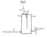
- a viscometer 12 is provided, receiving ink from the same filter 18 through which ink is passed to the head assembly.
- the viscometer has an overflow/vent pipe 34 which leads back to the reservoir 1.
- the outlet from the viscometer is at a level above that of the inlet to allow ink to remain in the base of the viscometer and keep the capillary tube continuously wetted with ink.
- the ink jet printer may have several print heads linked to a common ink supply.
- a measurement of the time t can provide an indication of the viscosity of the liquid.
- the viscometer 12 used in this example has a container 29 with a pair of level sensors 30,31 to which a voltage is applied. Ink is fed into it through a flow restricting orifice capillary 32 (see Figure 2). As the ink and housing are electrically conductive, when a current flows between the lower level sensor 30 and the housing the liquid is at the lower level. When there is current flow between the upper rod 31 and the housing the liquid is at the level of the upper rod. The time taken for the viscometer container to fill from the first sensor level 30 to the second sensor level 31 can thus be determined and is monitored by the control system CPU 38 ( Figure 4) to provide a measure of the viscosity (as described below).
- the CPU 38 causes the viscometer solenoid 13 to be opened in a line 33 back to the pump 11 so that the double ended pump 11 sucks ink from the viscometer prior to the measuring cycle starting again.
- Dependent upon the level of viscosity sensed by the control system signals are sent into the make-up solenoid 15 in order to allow solvents to be added to the ink to replace those lost through evaporation.
- the control system indicated in block diagram format in Figure 4 includes the pressure transducer 25 and a temperature sensor 35. Pressure and temperature signals are fed through an analogue/digital convertor 36 which can be pre-calibrated as required and the signals are then latched by means of a latch 37 through to the microprocessor CPU 38 under the control of suitable software residing in the system.
- the control system contains a PROM in which reside plural tables of flow time values for given temperatures and supply pressures so that the flow time in the viscometer measured by the CPU 38 can be corrected for measured temperature and pressure.
- the viscometer 12 is connected to the CPU 38 so that the level signals therefrom are passed to the CPU and the time measured, so that, after combination with the pressure and temperature signals and the information contained in the look-up tables in the PROM 39, the CPU can generate control signals by way of an interface 40 to the make-up solenoid 15. At the same time, signals from the interface 40 can be fed to suitable lamp displays 41 to indicate the state of operation of the viscometer.
- Operation of the viscometer is under CPU control, the primary control being the output solenoid 13.
- the output signal from the CPU which is fed to the makeup solenoid 15 can thus be highly accurate, being corrected for temperature and pressure variations as required (and thus the correct amount of solvent can be added to the ink system.
- a pressure relief valve can be used to supply a constant pressure of ink to the inlet to the measuring tank 32 ( Figure 2) and in this case a pressure transducer will not be required, nor will the memory need to contain pressure-related data.
- the operation of the solenoid 15 follows the flow chart shown in Figure 5, by means of which the filling and subsequent emptying of the tank 29 is controlled by the CPU 38 in order that viscosity is determined at appropriate intervals during the operational cycle, and, if necessary, solvent added to the ink to bring it to the desired viscosity.
Abstract
Description
- The present invention relates to a continuous ink jet printing system and in particular to a means of measuring the viscosity of ink in the system during use.
- In a continuous ink jet printing system ink is passed from a reservoir to a print head under pressure, the ink being forced through a nozzle and broken up into droplets which are charged according to the desired print position, the charged droplets then being deflected onto the target by an electrostatic field. Uncharged droplets are returned to the reservoir. During operation of the printer volatile solvents are lost from the ink due to evaporation so that the composition and physical properties of the ink change with time. It is known therefore to measure the viscosity of the ink and to introduce solvents into the ink to maintain the desired viscosity.
- In one known method, what is known as a "falling ball viscometer" is used, an upright tube being connected to a supply line for the ink and an element movable upwardly and downwardly within the tube being provided. A valve is positioned to control the flow of liquid from the supply line to the tube and a control means is arranged to open the valve to allow upwards flow of liquid in the tube sufficient to move the element to an upper part of the tube, subsequently closing the valve so as to terminate the upwards flow of liquid, and sensors being used to determine the time taken for the element to descend through a predetermined distance through the liquid within the tube. The time taken for the element to fall a known distance is representative of the viscosity of the liquid. Depending on the time measured so the ink is charged with a component which causes a change in the viscosity to correct the difference between the measured viscosity and the desired viscosity.
- In this method the clearance between the falling ball and the fluted wall of the tube is only a few microns and particles of ink and/or agglomerates of pigments or foreign bodies, if present, can seriously impede the free movement of the ball as it passes through the liquid thus causing incorrect measurement.
- According to the present invention a continuous ink jet printing system which comprises an ink circuit including an ink reservoir; a pump; a nozzle from which a continuous stream of ink droplets is projected in use under pressure from the pump; a device for collecting unused droplets; and a recirculation circuit for returning unused ink to the ink reservoir, further includes a means for determining the viscosity of the ink at selected intervals, the viscosity determining means having a measuring tank; an inlet to the tank connected to the ink circuit to receive ink under pressure, the inlet having a flow restriction; a vent/return pipe to vent the tank and enable ink to be returned to the reservoir; an outlet for draining ink from the tank and returning it to the pump, the outlet including a valve to open and close the outlet; a level detector in the tank; and a timer to determine the time taken for the tank to fill from a first level to a second level detected by the level detector and hence to provide a representation of the viscosity of the ink.
- Preferably, the temperature of the ink is monitored and the measured flow time is compared with the theoretical flow time at that temperature and if significantly different the viscosity of the ink is varied to bring it within range.
- Preferably, a means is provided for charging the ink with a component which causes a change in the viscosity to maintain the desired viscosity, the charging means being controlled in dependence upon the time determined by the timer.
- The invention also includes a continuous ink jet printing method using such a system, in which, at selected intervals, a valve in the outlet from the measuring tank is first opened to allow the tank to be emptied, and then closed to allow the tank to fill; a first signal is provided when the level of ink in the tank reaches a first level; a second signal is provided when the level of liquid in the tank reaches a second level; the time taken for the ink level to rise from the first level to the second level is measured and the outlet valve from the measuring tank is then opened to lower the level of ink in the tank to a level below the first level.
- A temperature sensing transducer may be provided in or near the inlet to the measuring tank to provide a signal indicative of the ink temperature, which signal may be sent to a microprocessor together with a signal indicative of the viscosity (a signal derived from the time taken for the tank to fill from the first to the second level), in order to provide a control signal to control the viscosity the ink.
- In addition a pressure sensing transducer may be provided in or near the inlet to the measuring tank to provide a signal indicative of the ink pressure, which signal may be sent to a microprocessor together with a signal from the viscometer of the filling time and a signal indicative of the temperature of the ink, in order to allow the microprocessor to accurately calculate the viscosity of the ink, and compare this with the required viscosity which is stored in memory. A control signal is sent to control charging of the viscosity adjusting component into the ink.
- A particular advantage of this apparatus and method is that the pressure of ink supplied to the nozzle is regulated at about 40 psi (2.76 × 10⁵ Pa) so that ink at this pressure can be fed to the viscometer. For a given temperature, experiment has shown that pressure variations as high as 5 psi (3.45 × 10⁴ Pa) lead only to a maximum calculated viscosity variation of about 5.6 × 10⁻⁴ Pa.s - within the limits required for consistent print quality. The, if desired, measurement of actual pressure can be dispensed with as far as the viscosity measuring part of the system is concerned.
- One example of a system constructed in accordance with the present invention will now be described with reference to the accompanying drawing in which:-
- Figure 1 illustrates, schematically, an ink jet printing system;
- Figure 2 illustrates a viscometer therefor;
- Figure 3 is a graph of fluid flow time through a capillary and temperature for various constant pressures;
- Figure 4 shows schematically, a block diagram of the viscosity measuring and control system; and,
- Figure 5 is a flow chart of viscosity measuring and control system.
- The ink system shown in Figure 1 conveys ink from an ink reservoir 1 to a print head assembly which includes a
nozzle head 16 and agutter 22 by means of which drops which are not used for printing are returned to the ink system. - The reservoir 1 is topped up from an ink cartridge 5 which can be replaced when empty and which provides top-up to the ink reservoir 1. A make-
up cartridge 6 contains solvents which can be added to the ink to make up for loss of solvent due to evaporation from non-printed droplets returned through thegutter 22. The make-up cartridge feeds solvents through a filter 14 on demand via aline 7 through asolenoid valve 15 to the main return line from thegutter 22. - Continuous ink jet printing is well known and the system will not be described in detail, but in brief the
nozzle assembly 16 includes a piezo-electric transducer (not shown) which breaks a flow of ink into individual droplets which are then electrostatically charged by a variable amount in order to suit the desired print position on the target, unprinted drops being substantially uncharged. The stream of droplets passes between a pair of deflection electrodes, the electric field between which causes the charged droplets to be deflected by appropriate amounts and into their desired positions on target. The levels of charge on the individual droplets are controlled by a print microprocessor (not shown in Figure 1). - From the ink reservoir 1 the ink is passed by means of a double-
ended pump 11 through a pressure relief valve 8 (to ensure that the ink pressure does not rise above 60 psi (4.14× 10⁵ Pa) in the line to the head assembly), ink for printing being led off between the double ended pump and the pressure relief valve 8 through a manually adjustable pressure regulator 17 (the pressure being monitored by an operator through agauge 20 or sensed automatically by a pressure transducer 25), through afurther filter 18, through afeed solenoid 19 and afurther filter 24 to thenozzle assembly 16. A bleed line is provided from thenozzle head 16 to return a mixture of ink and entrained air from the head at start-up and shut-down, this being achieved through ableed solenoid 21. - On the return side ink is passed through a
bleed control orifice 10 back to the double endedpump 11 and thence to the ink reservoir again. This ensures that the pump applies sufficient suction and is adequately lubricated, the bleed control orifice being preset to allow a predetermined flow of ink to the pump. The junction between the pressure release valve 8 and the line to thebleed control orifice 10 is connected back to the reservoir via a furtherpressure relief valve 9 which opens if the pressure of ink in the bleed line exceeds 1 psi (6.895 × 10³ Pa). - The operation of the pump motor and the various valves is controlled by a further microprocessor (not shown) linked to the print microprocessor. The ink control system (see Figure 4) for the system needs to monitor solvent loss and this is achieved indirectly by monitoring the viscosity of the ink. A
viscometer 12 is provided, receiving ink from thesame filter 18 through which ink is passed to the head assembly. - The viscometer has an overflow/
vent pipe 34 which leads back to the reservoir 1. The outlet from the viscometer is at a level above that of the inlet to allow ink to remain in the base of the viscometer and keep the capillary tube continuously wetted with ink. - The ink jet printer may have several print heads linked to a common ink supply.
- From theoretical considerations of the flow of liquid through a vertical capillary, viscosity at standard temperature can be deduced from the following:-

d = capillary diameter (mm)
ΔP = pressure drop across the capillary (Pa)
t = time (sec) for a volume of liquid V(mm³) to flow
L = length of tube (mm) - The above equation assumes that at the exit of the tube the stream has no energy. In most cases this is not the case, and the source of this energy is the pressure applied to the fluid. This can be corrected for by the addition of a second term to the equation giving:

ρ = density
m =²/₃ for square ended capillaries and 2 for trumpet shaped ends - Under certain conditions, long flow times for example, the energy correction can be ignored. Other correction terms can compensate for end effects, elastic deformation, turbulence etc, but are insignificant in this application.
- Thus, it will be appreciated that with all other terms remaining substantially constant, a measurement of the time t can provide an indication of the viscosity of the liquid.
- In an ink jet printing system as described above the ink is pressurized by the
pump 11. Theviscometer 12 used in this example has acontainer 29 with a pair oflevel sensors lower level sensor 30 and the housing the liquid is at the lower level. When there is current flow between theupper rod 31 and the housing the liquid is at the level of the upper rod. The time taken for the viscometer container to fill from thefirst sensor level 30 to thesecond sensor level 31 can thus be determined and is monitored by the control system CPU 38 (Figure 4) to provide a measure of the viscosity (as described below). When the level of ink reaches thetop sensor 31 theCPU 38 causes theviscometer solenoid 13 to be opened in aline 33 back to thepump 11 so that the double endedpump 11 sucks ink from the viscometer prior to the measuring cycle starting again. Dependent upon the level of viscosity sensed by the control system signals are sent into the make-up solenoid 15 in order to allow solvents to be added to the ink to replace those lost through evaporation. - It will be appreciated that the viscosity varies with temperature and this can be seen from Figure 3 in which the flow times, through a capillary of length L = 46mm and diameter d = 0.15mm, of a printing ink are shown plotted against temperature for a range of different pressures.
- The control system indicated in block diagram format in Figure 4 includes the
pressure transducer 25 and atemperature sensor 35. Pressure and temperature signals are fed through an analogue/digital convertor 36 which can be pre-calibrated as required and the signals are then latched by means of alatch 37 through to themicroprocessor CPU 38 under the control of suitable software residing in the system. The control system contains a PROM in which reside plural tables of flow time values for given temperatures and supply pressures so that the flow time in the viscometer measured by theCPU 38 can be corrected for measured temperature and pressure. - The
viscometer 12 is connected to theCPU 38 so that the level signals therefrom are passed to the CPU and the time measured, so that, after combination with the pressure and temperature signals and the information contained in the look-up tables in thePROM 39, the CPU can generate control signals by way of aninterface 40 to the make-upsolenoid 15. At the same time, signals from theinterface 40 can be fed to suitable lamp displays 41 to indicate the state of operation of the viscometer. - Operation of the viscometer is under CPU control, the primary control being the
output solenoid 13. The output signal from the CPU which is fed to themakeup solenoid 15 can thus be highly accurate, being corrected for temperature and pressure variations as required (and thus the correct amount of solvent can be added to the ink system. - Alternatively, a pressure relief valve can be used to supply a constant pressure of ink to the inlet to the measuring tank 32 (Figure 2) and in this case a pressure transducer will not be required, nor will the memory need to contain pressure-related data.
- The operation of the
solenoid 15 follows the flow chart shown in Figure 5, by means of which the filling and subsequent emptying of thetank 29 is controlled by theCPU 38 in order that viscosity is determined at appropriate intervals during the operational cycle, and, if necessary, solvent added to the ink to bring it to the desired viscosity.
Claims (6)
Applications Claiming Priority (2)
| Application Number | Priority Date | Filing Date | Title |
|---|---|---|---|
| GB8530885 | 1985-12-16 | ||
| GB858530885A GB8530885D0 (en) | 1985-12-16 | 1985-12-16 | Ink jet printing system |
Publications (3)
| Publication Number | Publication Date |
|---|---|
| EP0228828A2 true EP0228828A2 (en) | 1987-07-15 |
| EP0228828A3 EP0228828A3 (en) | 1988-08-24 |
| EP0228828B1 EP0228828B1 (en) | 1991-09-11 |
Family
ID=10589802
Family Applications (1)
| Application Number | Title | Priority Date | Filing Date |
|---|---|---|---|
| EP86309465A Expired - Lifetime EP0228828B1 (en) | 1985-12-16 | 1986-12-04 | Continuous ink jet printing system |
Country Status (5)
| Country | Link |
|---|---|
| US (1) | US4714931A (en) |
| EP (1) | EP0228828B1 (en) |
| JP (1) | JPS62140849A (en) |
| DE (1) | DE3681425D1 (en) |
| GB (1) | GB8530885D0 (en) |
Cited By (9)
| Publication number | Priority date | Publication date | Assignee | Title |
|---|---|---|---|---|
| WO1991017052A1 (en) * | 1990-05-03 | 1991-11-14 | Domino Printing Sciences Plc | Ink supply system for continuous ink jet printer |
| WO1992006364A1 (en) * | 1990-10-06 | 1992-04-16 | Willett International Limited | Device for measuring viscosity |
| EP0568419A1 (en) * | 1992-04-30 | 1993-11-03 | Imaje S.A. | Optimisation method for operating an ink-jet printer and printer implementing the method |
| EP0571785A2 (en) * | 1992-05-29 | 1993-12-01 | SCITEX DIGITAL PRINTING, INC. (a Massachusetts corp.) | Print head assembly |
| EP0646470A2 (en) * | 1993-09-08 | 1995-04-05 | Hitachi, Ltd. | An ink jet printing apparatus and a printing head for such an ink jet printing apparatus |
| WO1996008373A1 (en) * | 1994-09-16 | 1996-03-21 | Videojet Systems International, Inc. | Continuous ink jet printing system for use with hot-melt inks |
| EP2241442A3 (en) * | 2008-01-28 | 2010-10-27 | Hitachi Industrial Equipment Systems Co., Ltd. | Ink jet recording device |
| US8388118B2 (en) | 2007-03-27 | 2013-03-05 | Linx Printing Technologies Ltd. | Ink jet printing |
| EP3210786A1 (en) * | 2016-02-26 | 2017-08-30 | Dover Europe Sàrl | Method and device for adding solvent in small quantities |
Families Citing this family (17)
| Publication number | Priority date | Publication date | Assignee | Title |
|---|---|---|---|---|
| GB8725465D0 (en) * | 1987-10-30 | 1987-12-02 | Linx Printing Tech | Ink jet printers |
| US4860027A (en) * | 1988-03-18 | 1989-08-22 | A. B. Dick Company | Ink drop control system with temperature compensation |
| US4827280A (en) * | 1988-08-09 | 1989-05-02 | A. B. Dick Company | Flow rate control system |
| FR2652540B1 (en) * | 1989-10-02 | 1995-06-02 | Imaje Sa | INK CIRCUIT, IN PARTICULAR FOR PRESSURIZING A PIGMENT INK FOR AN INK JET PRINTER. |
| NL9302025A (en) * | 1993-11-23 | 1995-06-16 | Cornelis Gerardus Van Der Lans | Viscosity controller of printing ink |
| WO1998017478A1 (en) * | 1996-10-23 | 1998-04-30 | Domino Printing Sciences Plc | Continuous ink jet printer pump control |
| US6206511B1 (en) | 1998-06-19 | 2001-03-27 | Lexmark International, Inc. | Multiple-cartridge off-board ink supplies for color ink jet printers |
| DE19859436B4 (en) * | 1998-12-22 | 2009-12-24 | Heidelberger Druckmaschinen Ag | Digital color dosage |
| FR2792874B1 (en) * | 1999-04-28 | 2001-06-22 | Imaje Sa | INK-JET PRINTER AND METHOD FOR MANAGING THE QUALITY OF THE INK OF SUCH A PRINTER |
| US6742882B2 (en) * | 2001-06-26 | 2004-06-01 | Brother Kogyo Kabushiki Kaisha | Air purge device for ink jet recording apparatus |
| US6883904B2 (en) | 2002-04-24 | 2005-04-26 | Eastman Kodak Company | Apparatus and method for maintaining constant drop volumes in a continuous stream ink jet printer |
| US6955425B2 (en) * | 2002-04-26 | 2005-10-18 | Hewlett-Packard Development Company, L.P. | Re-circulating fluid delivery systems |
| JP4371725B2 (en) * | 2002-07-16 | 2009-11-25 | キヤノン株式会社 | Inkjet recording device |
| JP5274172B2 (en) * | 2008-09-17 | 2013-08-28 | 株式会社日立産機システム | Inkjet recording device |
| WO2011020022A1 (en) * | 2009-08-13 | 2011-02-17 | Sun Chemical Corporation | Temperature control in gravure and flexographic printing by aqueous fluid injection into the ink |
| JP5381678B2 (en) * | 2009-12-15 | 2014-01-08 | 株式会社リコー | Image forming apparatus |
| JP7050140B1 (en) * | 2020-12-21 | 2022-04-07 | 株式会社デンソーテン | Mixing equipment and method |
Citations (2)
| Publication number | Priority date | Publication date | Assignee | Title |
|---|---|---|---|---|
| JPS5653078A (en) * | 1979-10-05 | 1981-05-12 | Ricoh Co Ltd | Ink feeder in ink jet recorder |
| US4527170A (en) * | 1982-06-17 | 1985-07-02 | Ricoh Company Ltd. | Ink jet waste and replenish ink system |
Family Cites Families (3)
| Publication number | Priority date | Publication date | Assignee | Title |
|---|---|---|---|---|
| US3761953A (en) * | 1972-10-24 | 1973-09-25 | Mead Corp | Ink supply system for a jet ink printer |
| US4121222A (en) * | 1977-09-06 | 1978-10-17 | A. B. Dick Company | Drop counter ink replenishing system |
| US4555709A (en) * | 1984-04-12 | 1985-11-26 | The Mead Corporation | Ink reconstitution system and method for ink drop printer |
-
1985
- 1985-12-16 GB GB858530885A patent/GB8530885D0/en active Pending
-
1986
- 1986-12-04 DE DE8686309465T patent/DE3681425D1/en not_active Expired - Fee Related
- 1986-12-04 EP EP86309465A patent/EP0228828B1/en not_active Expired - Lifetime
- 1986-12-10 US US06/940,094 patent/US4714931A/en not_active Expired - Fee Related
- 1986-12-16 JP JP61299797A patent/JPS62140849A/en active Pending
Patent Citations (2)
| Publication number | Priority date | Publication date | Assignee | Title |
|---|---|---|---|---|
| JPS5653078A (en) * | 1979-10-05 | 1981-05-12 | Ricoh Co Ltd | Ink feeder in ink jet recorder |
| US4527170A (en) * | 1982-06-17 | 1985-07-02 | Ricoh Company Ltd. | Ink jet waste and replenish ink system |
Non-Patent Citations (1)
| Title |
|---|
| PATENT ABSTRACTS OF JAPAN, vol. 5, no. 112 (M-79)[784], 21st July 1981; & JP-A-56 053 078 (RICOH K.K.) 12-05-1981 * |
Cited By (20)
| Publication number | Priority date | Publication date | Assignee | Title |
|---|---|---|---|---|
| WO1991017052A1 (en) * | 1990-05-03 | 1991-11-14 | Domino Printing Sciences Plc | Ink supply system for continuous ink jet printer |
| WO1992006364A1 (en) * | 1990-10-06 | 1992-04-16 | Willett International Limited | Device for measuring viscosity |
| US5701149A (en) * | 1992-04-30 | 1997-12-23 | Imaje | Method to optimize the operation of an ink-jet printer, and a printer using such a method |
| EP0568419A1 (en) * | 1992-04-30 | 1993-11-03 | Imaje S.A. | Optimisation method for operating an ink-jet printer and printer implementing the method |
| FR2690648A1 (en) * | 1992-04-30 | 1993-11-05 | Imaje | A method of optimizing the operation of an ink jet printer and printer using such a method. |
| EP0571785A2 (en) * | 1992-05-29 | 1993-12-01 | SCITEX DIGITAL PRINTING, INC. (a Massachusetts corp.) | Print head assembly |
| EP0571785A3 (en) * | 1992-05-29 | 1995-04-05 | Eastman Kodak Co | Four inch print head assembly. |
| EP0646470A2 (en) * | 1993-09-08 | 1995-04-05 | Hitachi, Ltd. | An ink jet printing apparatus and a printing head for such an ink jet printing apparatus |
| EP0646470A3 (en) * | 1993-09-08 | 1995-09-06 | Hitachi Ltd | An ink jet printing apparatus and a printing head for such an ink jet printing apparatus. |
| US5821963A (en) * | 1994-09-16 | 1998-10-13 | Videojet Systems International, Inc. | Continuous ink jet printing system for use with hot-melt inks |
| WO1996008373A1 (en) * | 1994-09-16 | 1996-03-21 | Videojet Systems International, Inc. | Continuous ink jet printing system for use with hot-melt inks |
| US8388118B2 (en) | 2007-03-27 | 2013-03-05 | Linx Printing Technologies Ltd. | Ink jet printing |
| US8684504B2 (en) | 2007-03-27 | 2014-04-01 | Linx Printing Technologies Ltd. | Ink jet Printing |
| EP2241442A3 (en) * | 2008-01-28 | 2010-10-27 | Hitachi Industrial Equipment Systems Co., Ltd. | Ink jet recording device |
| US8308282B2 (en) | 2008-01-28 | 2012-11-13 | Hitachi Industrial Equipment Systems Co., Ltd. | Ink jet recording device |
| US8333463B2 (en) | 2008-01-28 | 2012-12-18 | Hitachi Industrial Equipment Systems Co., Ltd. | Ink jet recording device |
| US8337004B2 (en) | 2008-01-28 | 2012-12-25 | Hitachi Industrial Equipment Systems Co., Ltd. | Ink jet recording device |
| EP3210786A1 (en) * | 2016-02-26 | 2017-08-30 | Dover Europe Sàrl | Method and device for adding solvent in small quantities |
| FR3048200A1 (en) * | 2016-02-26 | 2017-09-01 | Dover Europe Sarl | METHOD AND DEVICE FOR ADDING SOLVENT BY SMALL QUANTITIES |
| US10011119B2 (en) | 2016-02-26 | 2018-07-03 | Dover Europe Sárl | Method and device for adding solvent in small quantities |
Also Published As
| Publication number | Publication date |
|---|---|
| EP0228828B1 (en) | 1991-09-11 |
| GB8530885D0 (en) | 1986-01-29 |
| DE3681425D1 (en) | 1991-10-17 |
| US4714931A (en) | 1987-12-22 |
| EP0228828A3 (en) | 1988-08-24 |
| JPS62140849A (en) | 1987-06-24 |
Similar Documents
| Publication | Publication Date | Title |
|---|---|---|
| EP0228828B1 (en) | Continuous ink jet printing system | |
| CA1238238A (en) | Ink drop velocity control system | |
| EP0333325A2 (en) | Ink drop control system with temperature compensation | |
| US4658268A (en) | Hydraulic system for recirculating liquid | |
| DE19906826B4 (en) | Pressure-based ink level detector and method for detecting an ink level | |
| US5731824A (en) | Ink level sensing system for an ink jet printer | |
| KR101075347B1 (en) | Systems and methods for measurement of low liquid flow rates | |
| US20020188410A1 (en) | Method for the controlled proportioning of liquids while dislocating a gas cushion | |
| CA2201867A1 (en) | Liquid level sensor for ink jet printers | |
| US4362179A (en) | Method and apparatus for controlling ink viscosity | |
| JPH06182975A (en) | Fluid height detection system | |
| CN101137901B (en) | Filtration tester and method for predicting to which extent a printing ink would lead to a clogging of a printer nozzle | |
| US4575735A (en) | Droplet depositing viscosity line-pressure sensing control for fluid re-supply | |
| US6494645B1 (en) | Method and device for determining a powder quantity or change in powder quantity in a container | |
| US6629455B2 (en) | Method of determining the throughflow of a gas mixture | |
| US4555709A (en) | Ink reconstitution system and method for ink drop printer | |
| US2565616A (en) | Pressure regulator | |
| EP0142265A1 (en) | Hydraulic systems for ink jet printers | |
| EP0652831B1 (en) | Ink jet printers and methods for their operation | |
| GB2032627A (en) | Flow measurement | |
| JPS61265531A (en) | Apparatus for detecting liquid level | |
| WO1992006364A1 (en) | Device for measuring viscosity | |
| JPH05338201A (en) | Ink-jet recording device | |
| JPS61266938A (en) | Detector for viscosity of liquid | |
| JP2524662B2 (en) | Device for measuring alcohol content of moisturizing fluids |
Legal Events
| Date | Code | Title | Description |
|---|---|---|---|
| PUAI | Public reference made under article 153(3) epc to a published international application that has entered the european phase |
Free format text: ORIGINAL CODE: 0009012 |
|
| AK | Designated contracting states |
Kind code of ref document: A2 Designated state(s): DE FR GB |
|
| PUAL | Search report despatched |
Free format text: ORIGINAL CODE: 0009013 |
|
| AK | Designated contracting states |
Kind code of ref document: A3 Designated state(s): DE FR GB |
|
| 17P | Request for examination filed |
Effective date: 19890216 |
|
| 17Q | First examination report despatched |
Effective date: 19900813 |
|
| GRAA | (expected) grant |
Free format text: ORIGINAL CODE: 0009210 |
|
| AK | Designated contracting states |
Kind code of ref document: B1 Designated state(s): DE FR GB |
|
| REF | Corresponds to: |
Ref document number: 3681425 Country of ref document: DE Date of ref document: 19911017 |
|
| ET | Fr: translation filed | ||
| PLBE | No opposition filed within time limit |
Free format text: ORIGINAL CODE: 0009261 |
|
| STAA | Information on the status of an ep patent application or granted ep patent |
Free format text: STATUS: NO OPPOSITION FILED WITHIN TIME LIMIT |
|
| 26N | No opposition filed | ||
| PGFP | Annual fee paid to national office [announced via postgrant information from national office to epo] |
Ref country code: GB Payment date: 19941125 Year of fee payment: 9 |
|
| PGFP | Annual fee paid to national office [announced via postgrant information from national office to epo] |
Ref country code: FR Payment date: 19941209 Year of fee payment: 9 |
|
| PG25 | Lapsed in a contracting state [announced via postgrant information from national office to epo] |
Ref country code: GB Effective date: 19951204 |
|
| GBPC | Gb: european patent ceased through non-payment of renewal fee |
Effective date: 19951204 |
|
| PG25 | Lapsed in a contracting state [announced via postgrant information from national office to epo] |
Ref country code: FR Effective date: 19960830 |
|
| REG | Reference to a national code |
Ref country code: FR Ref legal event code: ST |
|
| PGFP | Annual fee paid to national office [announced via postgrant information from national office to epo] |
Ref country code: DE Payment date: 19971212 Year of fee payment: 12 |
|
| PG25 | Lapsed in a contracting state [announced via postgrant information from national office to epo] |
Ref country code: DE Free format text: LAPSE BECAUSE OF NON-PAYMENT OF DUE FEES Effective date: 19991001 |